
In order to promote public education and public safety, equal justice for all, a better informed citizenry, the rule of law, world trade and world peace, this legal document is hereby made available on a noncommercial basis, as it is the right of all humans to know and speak the laws that govern them.
 Standards for Safety
ARCHIVE DOCUMENT
ii iii
Underwriters’ Laboratories, Inc., Chicago, Illinois
UNDERWRITERS’ LABORATORIES, INC. is chartered as a non-profit organization without capital stock, under the laws of the State of Delaware, to establish, maintain, and operate laboratories for the examination and testing of devices, systems, and materials. Founded in 1894, the enterprise is sponsored by the American Insurance Association, and is operated for service, not for profit.
A complete description of the organization, purposes, and methods of Underwriters’ Laboratories, Inc. is given in a separate pamphlet entitled “TESTING FOR PUBLIC SAFETY.”
An enumeration of all the Laboratories’ Standards is given in a list of “Published Standards” and in each of the following regularly published Lists:
Electrical Construction Materials
Electrical Appliance and Utilization Equipment
Hazardous Location Equipment
Fire Protection Equipment
Building Materials
Gas and Oil Equipment
Accident, Automotive, and Burglary Protection Equipment
Bi-Monthly Supplement to All Lists
A copy of the current issue of any of the above-mentioned publications may be obtained upon request.
OFFICES AND TESTING STATIONS
207 East Ohio Street, Chicago, III. 60611
333 Pfingsten Road, Northbrook, III. 60062
1285 Walt Whitman Road, Melville, L. I., N. Y. 11746
1655 Scott Boulevard, Santa Clara, Calif. 95050
| Page | ||||
| STANDARD FOR STEEL ABOVEGROUND TANKS FOR FLAMMABLE AND COMBUSTIBLE LIQUIDS | 5 | |||
| Foreword | 5 | |||
| REQUIREMENTS | 6 | |||
| Scope | 6 | |||
| General | 6 | |||
| Materials | 6 | |||
| Horizontal Tanks | 7 | |||
| Sizes and Dimensions | 7 | |||
| Metal Thickness | 7 | |||
| Shell Joints | 7 | |||
| Heads and Head Joints | 8 | |||
| Compartment Tanks | 10 | |||
| Vent Opening | 13 | |||
| Tank Connections | 15 | |||
| Manholes | 19 | |||
| Vertical Tanks | 21 | |||
| Sizes and Dimensions | 21 | |||
| Metal Thickness | 21 | |||
| Fabrication | 21 | |||
| Weak Shell-To-Roof Joint Type Tanks | 22 | |||
| Tank Connections | 24 | |||
| Manholes | 26 | |||
| Heating Coils and Hot Wells | 33 | |||
| Manufacturing and Production Tests | 33 | |||
| Marking | 33 | |||
| LABEL SERVICE | 38 | |||
| General | 38 | |||
| Labels | 38 | |||
| Cost of Service | 39 | |||
| Responsibility of the Manufacturer | 39 | |||
| Tests by the Manufacturer | 40 | |||
| The Laboratories’ Inspector | 41 | |||
| General | 41 | |||
| Inspection Reports | 42 | |||
| Special Instructions | 42 | |||
| Method for Determining Thickness of Uncoated Sheet and Plate Steel | 43 | |||
The first edition of this Standard was titled “Horizontal and Vertical Aboveground Storage Tanks for Hazardous Liquids.” The second edition was titled “Aboveground Storage Tanks for Hazardous Liquids.”
First Edition—December, 1922
Second Edition— October, 1953
THIRD EDITION
First Impression_________May, 1968
1. This Standard represents the judgment of Underwriters’ Laboratories, Inc. as to the basic requirements for the construction and performance of the products to be listed under this classification. These requirements are based upon sound engineering principles, research, records of tests and field experience, and an appreciation of the problems of manufacture, installation, and use derived from consultation with and information obtained from manufacturers, users, inspection authorities, and others having specialized experience. They are subject to revision as further experience and investigation may show is necessary or desirable.
2. The observance of the requirements of this Standard by a manufacturer is one of the conditions of the continued listing of the manufacturer's product under this classification. Underwriters’ Laboratories, Inc., however, assumes no responsibility for the effect of such observance or nonobservance by the manufacturer upon the relations between the manufacturer and any other party or parties arising out of the sale or use of the product or otherwise.
3. A product which complies with these requirements will not necessarily be acceptable if, when examined and tested, it is found to have other features which impair the result contemplated by these requirements.
4. A product employing materials or having forms of construction differing from those detailed in these requirements may be examined and tested according to the intent of the requirements and, if found to be substantially equivalent, may be given recognition.
5. Many tests required by the Standards of Underwriters’ Laboratories, Inc. are inherently hazardous. Underwriters’ Laboratories, Inc. neither assumes nor accepts any responsibility for any injury or damage that may occur during or as the result of tests, wherever performed, whether performed in whole or in part by the manufacturer, and whether or not any equipment, facility, or personnel for or in connection with the test is furnished by the manufacturer.
56. These requirements cover horizontal and vertical atmospheric-type steel tanks intended for the storage aboveground of flammable and combustible liquids. These tanks are for stationary installations as covered by the Flammable and Combustible Liquids Code of the National Fire Protection Association, NFPA No. 30-1966.
7. Tanks covered by these requirements are cylindrical tanks which are fabricated, inspected, and tested for leakage before shipment from the factory as completely assembled vessels.
8. Capacities, dimensions, and construction details shall conform to the applicable requirements of this Standard.
9. A table of capacities per foot of length or height of cylindrical shells is given in Table XVIII for convenience in checking capacities of tanks of various diameters.
10. To provide for manufacturing variations, a plus tolerance of 10 percent in maximum capacity and a plus tolerance of 5 percent in either the maximum diameter or maximum length will be permitted for tanks constructed of No. 7 gage or heavier steel. This does not mean that a tank is to be designed intentionally to have a capacity, diameter, or length greater than the maximum designated herein.
11. A tank shall be constructed of commercial grade steel of good welding quality. Only new material shall be used. A tank shall be fabricated from steel not lighter than specified herein for its capacity and diameter.
12. The thickness of steel, as measured in accordance with paragraph 13 shall be not less than the appropriate minimum value given in Table I.
13. The thickness of steel is to be determined by five micrometer readings equally spaced along the edge of the full piece as rolled. Thickness is to be determined on the plate or sheet not less than ⅜ inch from a cut edge and not less than ¾ inch from a mill edge.
6| Thickness or Manufacturers’ Standard Gage No. | Nominal Thickness, Inches | Minimum Thickness Inches |
|---|---|---|
| ⅜ inch | 0.375 | 0.365 |
| 5/16 inch | 0.312 | 0.302 |
| ¼ inch | 0.250 | 0.240 |
| 7 gage | 0.179 | 0.167 |
| 9 gage | 0.150 | 0.138 |
| 10 gage | 0.135 | 0.123 |
| 12 gage | 0.105 | 0.093 |
14. A horizontal tank shall not exceed the maximum capacity and diameter specified in Table II.
15. The over-all length of a horizontal tank shall be not greater than six times its diameter, nor less than its diameter.
16. A horizontal tank shall be fabricated from steel not lighter than specified in Table II for its capacity and diameter. (See paragraphs 12 and 13.)
| Capacity U.S. Gallons | Maximum Diameter, Inches | Thickness of Steel |
|---|---|---|
| 550 or less | 48 | 12 gage |
| 551-1100 | 64 | 10 gage |
| 1101-9000 | 76 | 7 gage |
| 1101-35000 | 144 | ¼ inch |
| 35001-50000 | 144 | ⅜ inch |
| Table II corrected March, 1971—Standard for Steel Aboveground Tanks for Flammable and Combustible Liquids, Third Edition, Second Impression, UL 142-1969. | ||
17. Shell joints of horizontal tanks shall be one of the forms shown by Figure 1.
718. A head of a horizontal tank shall be fabricated of not more than three pieces for diameters of from 48 to 96 inches, and four pieces for diameters of from 97 to 144 inches. When two or more pieces are used, seams shall be one of the forms shown by Figure 1, except joint No. 5 shall not be used.
19. A head of a horizontal tank shall be attached to the shell by one of the joints shown by Figure 2.
20. A head of a horizontal tank may be flat or dished.
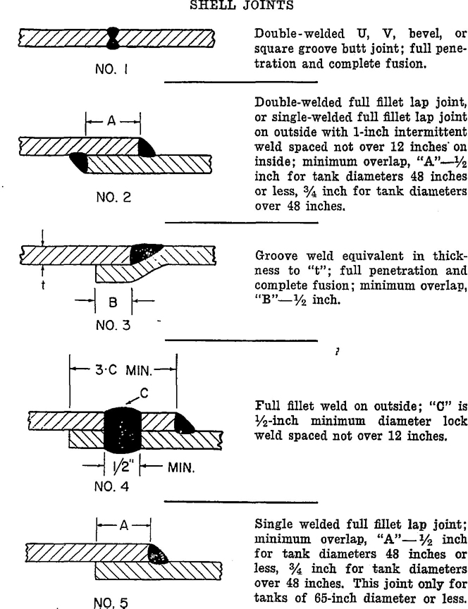
FIGURE 1
8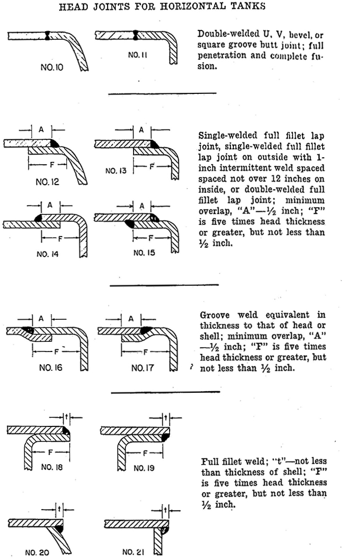
FIGURE 2
921. An unflanged flat head of a horizontal tank shall be braced in accordance with Figure 3.
22. A flanged flat head of a horizontal tank more than 72 inches in diameter shall be made of not less than 5/16–inch–thick material or it shall be braced in accordance with Figure 4.
23. A flanged flat head of a horizontal tank 72 inches or less in diameter is not required to be braced. A flanged flat head of a horizontal tank made of material 5/16-inch-thick or heavier is not required to be braced.
24. The depth of dish of a dished head shall be not less than that specified in Table III.
| Diameter | Minimum Dish | Diameter | Minimum Dish |
|---|---|---|---|
| Up to 5’ 0” | 1½ inches | 8’1” to 9’0” | 4½ inches |
| 5’ 1” to 6’ 0” | 2 inches | 9’1” to 10’ 0” | 5½ inches |
| 6’ 1” to 7’ 0” | 2½ inches | 10’ 1” to 11’ 0” | 7 inches |
| 7’ 1” to 8’ 0” | 3½ inches | 11’ 1” to 12’ 0” | 8 inches |
25. Bulkheads of compartment tanks shall be of such construction that any leakage through joints will be directed to the outside of the tank rather than from one compartment to another. See Figure 5 for acceptable bulkhead constructions.
26. A single bulkhead of a compartment tank, shown by Details 101 and 102 of Figure 5, shall be fabricated of one piece of material and may be flat or dished. The depth of dish of a dished bulkhead shall be not less than that specified in Table III.
27. A bulkhead of a double bulkhead tank, shown by Detail 100 of Figure 5, shall be fabricated of not more than three pieces for diameters of from 48 to 96 inches, and four pieces for diameters of from 97 to 144 inches. When two or more pieces are used, seams shall be one of the forms shown by Figure 1, except joint No. 5 shall not be used.
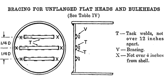
FIGURE 3
10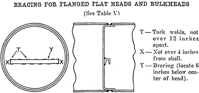
FIGURE 4
| Diameter of Head, Inches | Channels | Angles, Inches |
|---|---|---|
| Up to 60 | 3 inches—4.1 pounds | 2 × 2 × ⅜ or 2½ × 2½ × ¼ |
| 61 to 72 | 3 inches—4.1 pounds | 3 × 3 × 7/16 or 3½ × 3½ × 5/16 |
| 73 to 84 | 4 inches—5.4 pounds | 3½ × 3½ × ½ or 4 × 4 × ⅜ |
| 85 to 96 | 5 inches—6.7 pounds | 4 × 4 × ½ or 5 × 3½ × ⅜a |
| 97 to 108 | 5 inches—6.7 pounds | 4 × 4 × ¾ or 6 × 4 × ⅜a |
| 109 to 120 | 6 inches—8.2 pounds | 3 × 5 × ⅝ or 6 × 4 × ½a |
| 121 to 132 | 7 inches—9.8 pounds | 3 × 5 × ¾ or 6 × 4 × 9/16a |
| 133 to 144 | 7 inches—9.8 pounds | 3 × 5 × ¾ or 6 × 4 × 9/16a |
| a Short leg of angle welded to head. | ||
| Diameter of Head, Inches | I-Beams | Channels |
|---|---|---|
| 72 to 84 | 3 inches—5.7 pounds | 3 inches—4.1 pounds |
| 85 to 96 | 3 inches—5.7 pounds | 4 inches—5.4 pounds |
| 97 to 108 | 4 inches—7.7 pounds | 5 inches—6.7 pounds |
| 109 to 120 | 5 inches—10 pounds | 5 inches—6.7 pounds |
| 121 to 132 | 5 inches—10 pounds | 6 inches—8.2 pounds |
| 133 to 144 | 5 inches—10 pounds | 6 inches—8.2 pounds |
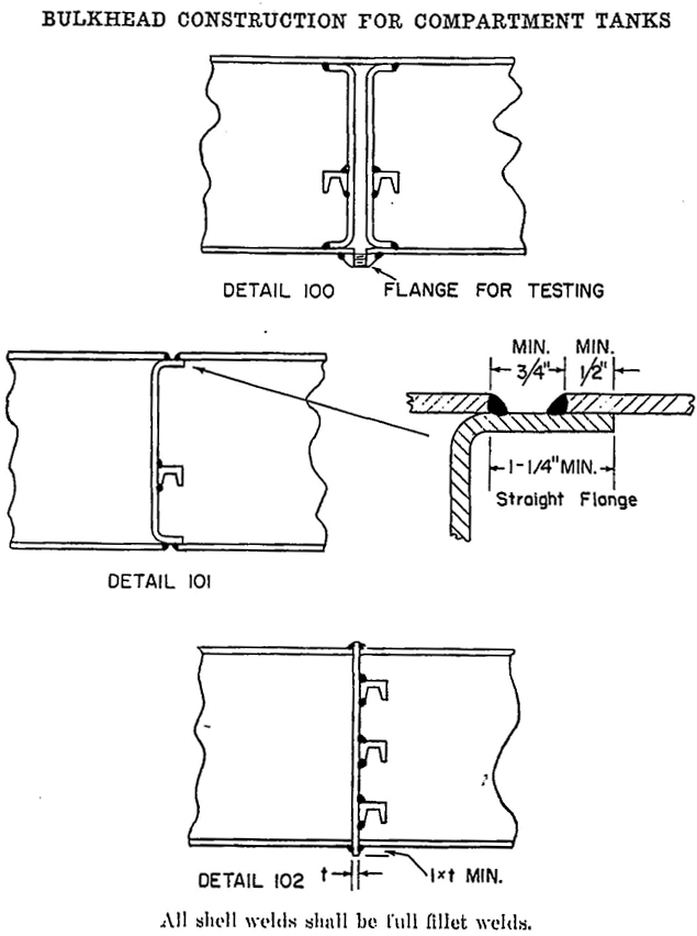
FIGURE 5
28. The thickness of metal employed for a bulkhead shall be not lighter than No. 7 gage for diameters of 76 inches or less and ¼ inch for diameters of over 76 inches.
29. An unflanged flat bulkhead of a compartment tank shall be braced in accordance with Figure 3.
30. A flanged flat bulkhead of a compartment tank more than 72 inches in diameter shall be made of not less than 5/16-inch-thick material or it shall be braced in accordance with Figure 4.
1231. A flanged flat bulkhead 72 inches or less in diameter is not required to be braced. A flanged flat bulkhead made of material 5/16 inch thick or heavier is not required to be braced.
32. Each horizontal tank and each compartment of a compartment tank shall have provision for both normal and emergency venting. A vent opening shall be in addition to the filling and withdrawal openings.
33. The provision for venting shall be an opening in accordance with paragraph 34, provided for that purpose only, or shall be a manhole with cover as described in paragraph 36 and a vent opening for normal venting conforming to paragraph 38.
34. A vent opening for emergency and normal venting shall have a capacity not less than that derived from Table VI.
| Wetted Surface, Square Feet | Venting Capacity, Cubic Feet Per Houra | Minimum Opening, Iron Pipe Size, Inchesb |
|---|---|---|
| 20 | 21,100 | 2 |
| 30 | 31,600 | 2 |
| 40 | 42,100 | 3 |
| 50 | 52,700 | 3 |
| 60 | 63,200 | 3 |
| 70 | 73,700 | 4 |
| 80 | 84,200 | 4 |
| 90 | 94,800 | 4 |
| 100 | 105,000 | 4 |
| 120 | 126,000 | 5 |
| 140 | 147,000 | 5 |
| 160 | 168,000 | 5 |
| 180 | 190,000 | 5 |
| 200 | 211,000 | 6 |
| 250 | 239,000 | 6 |
| 300 | 265,000 | 6 |
| 350 | 288,000 | 8 |
| 400 | 312,000 | 8 |
| 500 | 354,000 | 8 |
| 600 | 392,000 | 8 13 |
| 700 | 428,000 | 8 |
| 800 | 462,000 | 8 |
| 900 | 493,000 | 8 |
| 1000 | 524,000 | 10 |
| 1200 | 557,000 | 10 |
| 1400 | 587,000 | 10 |
| 1600 | 614,000 | 10 |
| 1800 | 639,000 | 10 |
| 2000 | 662,000 | 10 |
| 2400 | 704,000 | 10 |
| 2800 and over | 742,000 | 10 |
| a These values taken from NFPA No. 30–1966, published by National Fire Protection Association. b These pipe sizes apply only to open vent pipes of the indicated diameter not more than 12 inches long and a pressure in tank of not more than 2.5 pounds per square inch. If tank is to be equipped with venting device or flame arrester, the vent opening must accommodate the venting device or flame arrester sized in accordance with Column 2 of Table VI. |
||
35. The wetted area of horizontal tanks is calculated on the basis of 75 percent of the total exposed area. Values, to the nearest whole number, for wetted areas of flat-headed horizontal tanks of various diameters and lengths are included in Table XIX.
36. A manhole in the top of a tank, with a self-closing cover or a cover held in place only by long bolts that permit the cover to lift under internal pressure such that the pressure in the tank cannot exceed 2.5 pounds per square inch may serve for emergency venting. Where emergency venting is provided by such manhole and cover, the tank is to include a vent opening for normal venting in accordance with paragraph 38.
37. Emergency venting in accordance with paragraph 36 may be obtained by an arrangement which will permit the cover of a manhole not less than 16 inches in diameter to be lifted vertically not less than 1½ inches under conditions requiring emergency venting. See Figure 8 for manhole details.
38. Each tank provided with a manhole in accordance with paragraph 36 shall have a vent opening in the top of the tank for normal venting, which opening shall be in addition to the filling and withdrawal openings. The vent opening shall be not less than as specified in Table VII.
14| Capacity of Tank, U. S. Gallons | Minimum Diameter, Iron Pipe Size, Inches |
|---|---|
| Under 2500 | 1¼ |
| 2,500 to 3,000 | 1½ |
| 3,001 to 10,000 | 2 |
| 10,001 to 20,000 | 2½ |
| 20,001 to 35,000 | 3 |
| 35,001 to 50,000 | 4 |
39. Tank connections shall be provided for each opening by welding to the tank standard threaded pipe couplings, substantial threaded flanges, standard half pipe nipples, or by USA standard steel pipe flanges welded to lengths of standard pipe which, in turn, are welded to the tank. Connections at locations other than in the top shall be in accordance with Figure 7.
40. Fittings for connections shall be of steel of good welding quality. The minimum length of thread shall conform to the values specified in Table VIII.
41. Pressed-steel pipe-connecting fittings shall be installed with the hub section on the inside of the tank as shown by Detail 62 of Figure 6. The thickness of the flange section shall be not less than as specified in Table VIII.
| Nominal Pipe Size, Inch | Minimum Length of Thread, Inch | Thickness of Flange Section of Pressed-Steel Fittings | ||
|---|---|---|---|---|
| Gage No. | Nominal, Inch | Minimum, Inch | ||
| ¾ | ⅝ | 10 | 0.135 | 0.123 |
| 1 | ⅝ | 9 | 0.150 | 0.138 |
| 1¼ | 11/16 | 9 | 0.150 | 0.138 |
| 1½ | ¾ | 9 | 0.150 | 0.138 |
| 2 | ¾ | 9 | 0.150 | 0.138 |
| 2½ | 1 | 7 | 0.179 | 0.167 |
| 3 | 1 | 7 | 0.179 | 0.167 |
| 3½ | 1 | 7 | 0.179 | 0.167 |
| 4 | 1⅛ | 7 | 0.179 | 0.167 |
| 5 | 1 3/16 | — | — | — |
| 6 | 1¼ | — | — | — |
| 8 | 1⅜ | — | — | — |
42. All openings in a tank shall be closed with wooden plugs, metal covers, or their equivalent, to protect threads and exclude foreign matter while in storage or in transit.
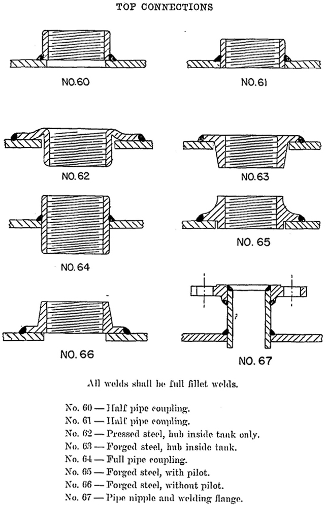
FIGURE 6
16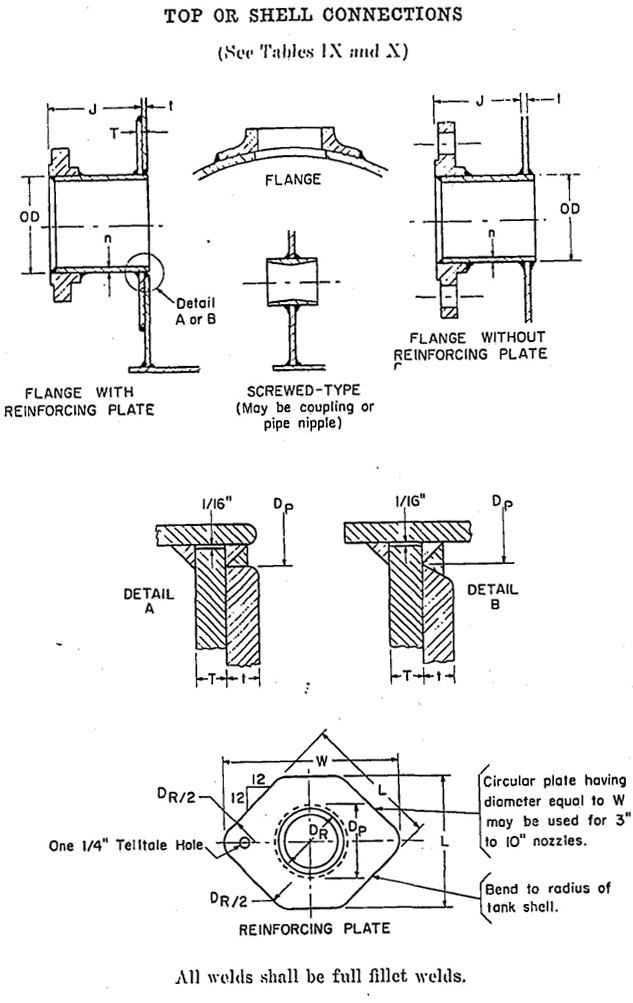
FIGURE 7
17| Size of Connection | Outside Diameter of Pipe | Minimum Thickness of Flanged Connection, Pipe Walla (n) |
Diameter of Hole in Reinforcing Plate (DR) |
Length of Side of Reinforcing Plate (L) |
Width of Reinforcing Plate (W) |
Minimum Distance from Shell to Flange Face (J) |
|---|---|---|---|---|---|---|
| Flanged Fittings | ||||||
| 24 | 24 | 0.50 | 24½ | 49½ | 60 | 12 |
| 22 | 22 | 0.50 | 22⅛ | 45½ | 55¼ | 11 |
| 20 | 20 | 0.50 | 20⅛ | 41½ | 50½ | 11 |
| 18 | 18 | 0.50 | 18⅛ | 37½ | 45¾ | 10 |
| 16 | 16 | 0.50 | 16⅛ | 33½ | 40¾ | 10 |
| 14 | 14 | 0.50 | 14⅛ | 29½ | 36 | 10 |
| 12 | 12¾ | 0.50 | 12⅞ | 27 | 33 | 9 |
| 10 | 10¾ | 0.50 | 10⅞ | 23 | 28¼ | 9 |
| 8 | 8⅝ | 0.50 | 8¾ | 19 | 23¼ | 8 |
| 6 | 6⅝ | 0.432 | 6¾ | 15¾ | 19½ | 8 |
| 4 | 4½ | 0.337 | 4⅝ | 12 | 15¼ | 7 |
| 3 | 3½ | 0.300 | 3⅝ | 10½ | 13½ | 7 |
| 2 | 2⅜ | 0.218 | 2½ | — | — | 6 |
| 1½ | 1-90 | 0.200 | 2 | — | — | 6 |
| a Extra-strong pipe, for sizes up to 12-inch, inclusive; for sizes over 12-inch to 24-inch, inclusive, refer to the latest edition of ASTM A-53, A-134, A-135, or A-139. Pipe made from formed plate electrically butt-welded may be substituted for any of the above-mentioned pipe sections. | ||||||
| Thickness of Shell and Reinforcing Plate (t) and (T) | Maximum Diameter of Hole in Shell Plate (DP) Equals Outside Diameter of Pipe Plus the Following Values |
|---|---|
| 3/16 inch | ⅝ inch |
| ¼ inch | ⅝ inch |
| ⅜ inch | ⅝ inch |
43. Each tank and each compartment of a compartment tank which is over 5000 gallons capacity shall incorporate a manhole.
44. Except as provided for in paragraph 45, a manhole for attachment to the top of a tank shall be as shown on Figure 8. A manhole attached to the shall at a location below the top of the head of a tank shall conform to Figure 9. The cover shall be provided with a gasket.
Paragraph 44 revised January, 1969 — Standard for Steel Aboveground Tanks for Flammable and Combustible Liquids, UL 142-1968
[Illegible Text Omitted on Page 19] under internal pressure. See paragraph 36.
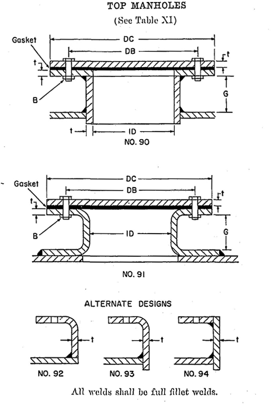
FIGURE 8
19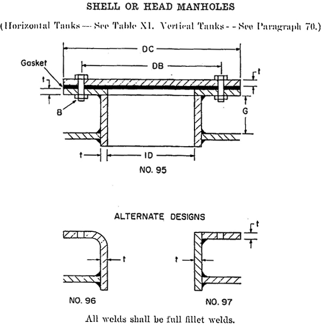
FIGURE 9
| Size of Manhole, Inches | Nominal Diameter of Neck (ID), Inches | Minimum Diameter of Cover Plate (DC), Inches | Minimum Diameter of Bolt Circle (DB), Inches | Minimum Number of Bolts |
|---|---|---|---|---|
| 16 | 16 | 20½ | 19 | 16 |
| 18 | 18 | 22½ | 21 | 18 |
| 20 | 20 | 24½ | 23 | 20 |
| 24 | 24 | 28½ | 27 | 24 |
| t — Not less than 3/16 inch. B — Minimum ½-inch bolts in 9/16-inch-diameter holes. G — Minimum 2 inches for tanks 6 feet in diameter or larger. Table XI revised January, 1969 — Standard for Steel Aboveground Tanks for Flammable and Combustible Liquids, UL 142-1968 |
||||
46. The minimum diameter of a vertical tank shall be not less than one-quarter of its height.
47. The shell height of a vertical tank shall be not more than 35 feet.
48. A vertical tank shall be fabricated from steel not lighter than specified in Table XII for its capacity. (See paragraphs 12 and 13.)
| Capacity, U. S. Gallons | Thickness of Steel | ||
|---|---|---|---|
| Shell | Bottom | Top | |
| 1100 or less | 12 gage | 12 gage | 12 gage |
| Over 1100 | 7 gagea | ¼ inch | 10 gage |
| a For a tank more than 25 feet in height, all parts of the shell located more than 25 feet below the top edge of the shell shall be not less than ¼ inch. | |||
49. The shell joints of vertical tanks shall be one of the joints shown in Figure 1.
50. Tops and bottoms of vertical tanks shall be fabricated of not more than four pieces. When two or more pieces are used, joints shall be one of the forms illustrated by Figure 1, except that joint No. 5 shall not be used.
51. Conical tops of vertical tanks shall have slopes not greater than inches in 12 inches. The height of conical tops shall be not less than nine-sixth of the radius of the tank when the top is made of steel lighter than No. 7 gage and shall be not less than one-twelfth of the radius of the tank when the top is made of No. 7 gage or heavier steel. A dished head shall have a depth of dish not less than that specified in Table III.
52. The bottoms of vertical tanks shall be attached to the shell by one of the joints shown in Figure 10.
53. The top of vertical tanks shall be dished or conical and attached to the shell by one of the joints shown in Figure 11.
54. Vertical tanks other than described in paragraph 58 shall have provision for both normal and emergency venting. A vent opening shall be in addition to the filling and withdrawal openings.
55. The provision for venting shall be an opening in accordance with paragraph 56, provided for that purpose only, or shall be a manhole with cover as described in paragraph 36 and a vent opening for normal venting conforming to paragraph 63.
56. A vent opening for emergency and normal venting shall have a capacity no less than that derived from Table VI.
2157. The wetted area of vertical tanks is calculated on the basis of the exposed shell area. For vertical tanks over 30 feet high, the first 30 feet of the shell above the bottom of the tank is included in the calculation. Values, to the nearest whole number, for wetted areas of vertical tanks of various diameters and heights are included in Table XX.
58. A weak shell-to-roof joint type of tank is a tank embodying a shell-to-roof attachment such as to obtain a frangible joint which, in the case of excessive internal pressure, will fail before failure occurs in the
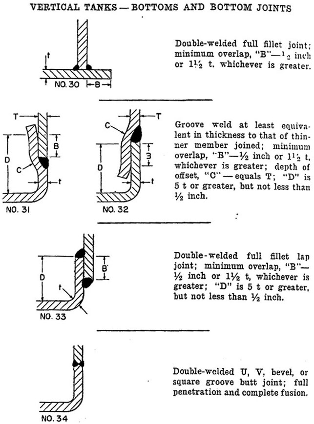
FIGURE 10
22tank shell joints or the shell-to-bottom joint, thus providing emergency relief venting. Vertical tanks complying with the requirement of paragraphs 59 and 62, inclusive, are considered to be weak shell-to-roof type tanks.
59. The diameter of a weak shell-to-roof type of tank shall be not less than 10 feet.
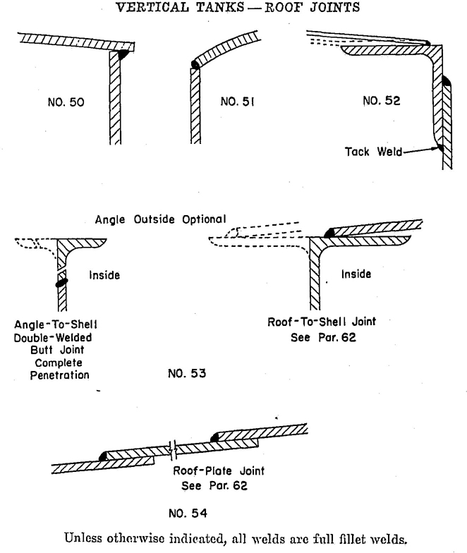
FIGURE 11
60. Except as required by paragraph 48 for tanks more than 25 feet in height, the shell of the tank shall be not heavier than No. 7 gage steel.
61. The top of vertical tanks constructed with weak shell-to-roof seam shall be conical, having a slope not greater than 2 inches in 12 inches, nor less than 1½ inches in 12 inches. The top shall be made of steel not heavier than No. 7 gage.
62. The roof of a vertical tank of the weak shell-to-roof joint type shall be attached to the top angle with a continuous single fillet weld on the top side only. The size of the weld shall be not larger than 3/16 inch. The top angle shall be not smaller than 2½ by 2½ by ¼ inch and shall be attached to the shell with a double-welded butt joint. See Detail 53 of Figure 11. Roof plates shall not be attached to supporting members. Roof-plate joints shall be as shown by Detail 54 of Figure 11.
Paragraphs 61 and 62 revised January, 1969 — Standard for Steel Aboveground Tanks for Flammable and Combustible Liquids, UL 142-1968
2362. The roof of a vertical tank of the weak shell-to-roof joint type shall be attached to the shell by a single fillet weld not over 3/16 inch on the outside only, as shown by Detail 53 of Figure 11. The top angle shall be not smaller than 2½ by 2½ by ¼ inch. Roof plates shall not be attached to supporting members. Roof-plate joints shall be as shown by Detail 54 of Figure 11.
63. Each tank constructed with a weak shell-to-roof joint or provided with a manhole in accordance with paragraph 36 shall have a vent opening for normal venting, which opening shall be in addition to the filling and withdrawal openings. The vent opening shall be not less than as specified in Table VII.
64. A weak shell-to-roof joint type of tank is not required to have emergency relief venting as specified in paragraph 54.
65. Tank connections shall be provided for each opening by welding to the tank standard threaded pipe couplings, substantial threaded flanges, standard half pipe nipples, or by USA standard steel pipe flanges welded to lengths of pipe which, in turn, are welded to the tank. Connections in the roof of a vertical tank shall be in accordance with Figures 6, 7, and 12. Connections in the shell of a vertical tank shall be in accordance with Figure 7.
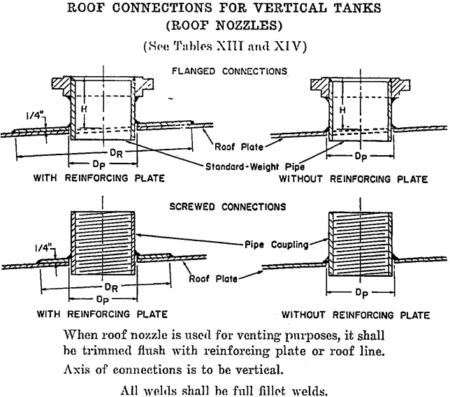
FIGURE 12
24| Nominal Size of Nozzle, Inches | Outside Diameter of Pipe Neck, Inches | Diameter of Hole in Roof Plate or Reinforcing Plate (DP), Inches | Height of Nozzle (H) Inches | Outside Diameter of Reinforcing Rate (DR) Inches |
|---|---|---|---|---|
| 1½ | 1.900 | 2 | 6 | 5 |
| 2 | 2⅜ | 2½ | 6 | 7 |
| 3 | 3½ | 3⅝ | 6 | 9 |
| 4 | 4½ | 4⅝ | 6 | 11 |
| 6 | 6⅝ | 6¾ | 6 | 15 |
| 8 | 8⅝ | 8⅞ | 6 | 18 |
| 10 | 10¾ | 11 | 8 | 22 |
| 12 | 12¾ | 13 | 8 | 21 |
| Nominal Size of Nozzle, Inches | Nominal Size of Coupling, Inches | Diameter of Hole in Roof Plate or Reinforcing Plate (DP), Inches | Outside Diameter of Reinforcing Rate (DR), Inches |
|---|---|---|---|
| ¾ | ¾ | 1 7/16 | 4 |
| 1 | 1 | 1 23/32 | 1½ |
| 1½ | 1½ | 2 11/32 | 5 |
| 2 | 2 | 3 | 7 |
| 3 | 3 | 4⅛ | 9 |
| 4 | 4 | 5 11/32 | 11 |
| 6 | 6 | 7 17/32 | 15 |
| 8 | 8 | 9⅞ | 18 |
| 10 | 10 | 12 | 22 |
| 12 | 12 | 14¼ | 21 |
66. Fittings for connections shall be of steel of good welding quality. The minimum length of thread shall conform to the values specified in Table VIII.
2567. Pressed-steel pipe-connecting fittings shall be installed with the hub section on the inside of the tank only as shown by Detail 62 of Figure 6. The thickness of the flange section shall be not less than that specified in Table VIII.
68. All openings in a tank shall be closed with wooden plugs, metal covers, or their equivalent, to protect threads and exclude foreign matter while in storage or in transit.
69. Each tank which is over 5000 gallons capacity shall incorporate a manhole.
70. A manhole for attachment to the roof of a tank shall be in accordance with Figure 8 or Figure 13. A manhole attached to the shell of a vertical tank shall conform to Figure 9 or Figure 14. A manhole of the type shown by Figure 9 shall conform to Tables XVI and XVII with respect to the diameter of cover plate and bolt circle, the size and number of bolts, and the minimum thickness of cover plate and bolting flange. The cover shall be provided with a gasket. The minimum bolt clearance (G dimension, Figure 9) shall be not less than 2 inches for tanks 6 feet in diameter or larger.
71. A cover for a manhole in the top of a tank may be of the self-closing type or may be secured by long bolts to permit the cover to lift under internal pressure. See Paragraph 36.
| Size of Manhole, Inches | Diameter of Neck (ID), Inches | Diameter of Cover Plate (DC), Inches | Diameter of Bolt Circle (DB), Inches | Minimum Number of Bolts | Diameter of Hole in Roof Plate or Reinforcing Plate (DP), Inches | Outside Diameter of Reinforcing Plate (DR), Inches |
|---|---|---|---|---|---|---|
| 16 | 16 | 20½ | 19 | 16 | 16⅝ | 38 |
| 18 | 18 | 22½ | 21 | 18 | 18⅝ | 40 |
| 20 | 20 | 24½ | 23 | 20 | 20⅝ | 42 |
| 24 | 24 | 28½ | 27 | 24 | 24⅝ | 46 |
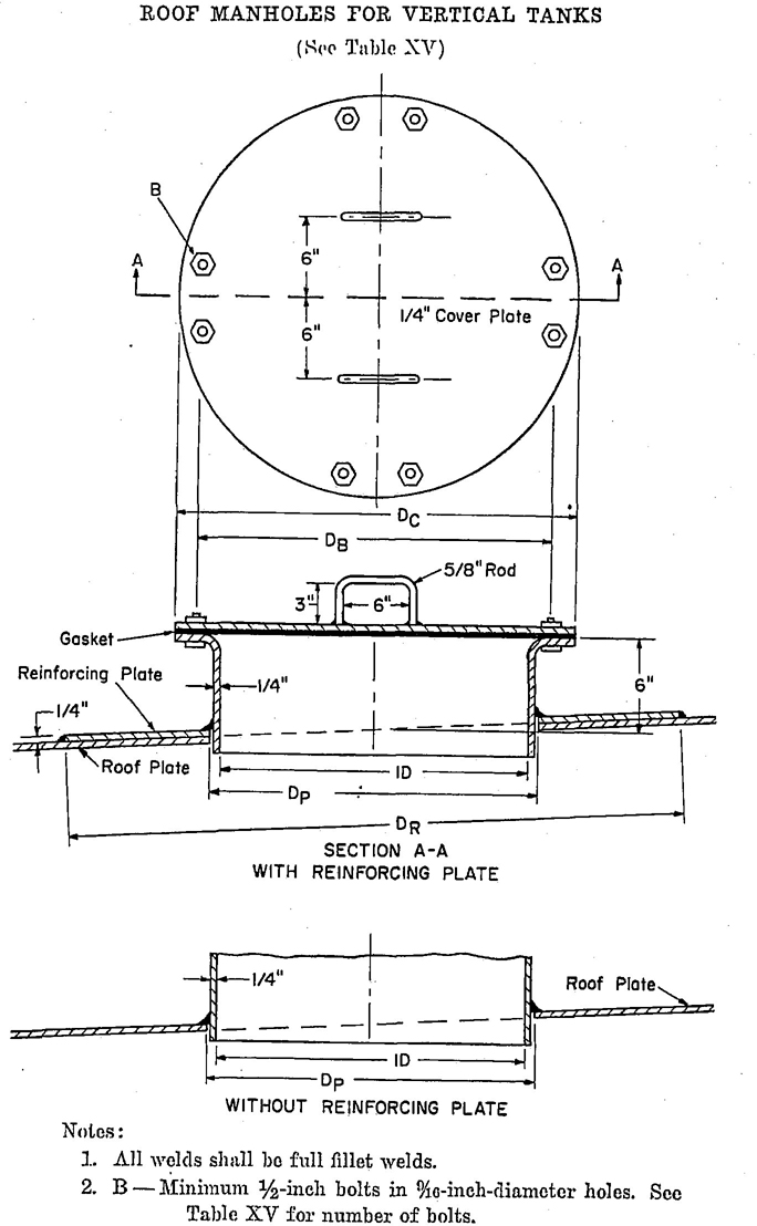
FIGURE 13
27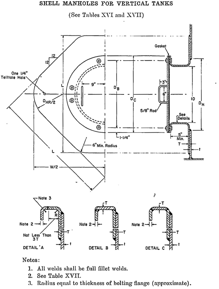
FIGURE 14
28| Frame Using Constant-Diameter Ring Die | Built-Up Frame or Frame Using Constant-Diameter Plug Die | ||||||
|---|---|---|---|---|---|---|---|
| Thickness of Shell and Manhole Attachment Flange (t) and (T) |
Approximate Radius (R) |
Attachment Flange | Inside Diameter of Manhole Frame (IDR) |
Maximum Diameter of Hole in Shell (DHR) |
Inside Diameter of Manhole Frame (IDp) |
Maximum Diameter of Hole in Shell (DHP) |
|
| Length of Side (L) | Width (W) | ||||||
| 16-Inch Shell Manhole | |||||||
| 7 gage | 3/16 | 38 | 45½ | 18⅝ | 20¼ | 16 | 17¾ |
| ¼ | ¼ | 38 | 45½ | 18½ | 20½ | 16 | 18 |
| Diameter of bolt circle DB = 22¼ inches. Diameter of cover plate DC = 24¾ inches. 20 ¾-inch-diameter bolts in ⅞-inch-diameter holes. |
|||||||
| 18-Inch Shell Manhole | |||||||
| 7 gage | 3/16 | 42 | 50½ | 20⅜ | 22¼ | 18 | 19¾ |
| ¼ | ¼ | 42 | 50½ | 20½ | 27½ | 18 | 20 |
| Diameter of bolt circle DB = 24¼ inches. Diameter of cover plate DC = 26¾ inches. 20 ¾-inch-diameter bolts in ⅞-inch-diameter holes. |
29 | ||||||
| 20-Inch Shell Manhole | |||||||
| 7 gage | 3/16 | 46 | 55 | 22⅝ | 24¼ | 20 | 21¾ |
| ¼ | ¼ | 46 | 55 | 22½ | 24½ | 20 | 22 |
| Diameter of bolt circle DB = 26¼ inches. Diameter of cover plate DC = 28¾ inches. 28 ¾-inch-diameter bolts in ⅞-inch-diameter holes. |
|||||||
| 24-Inch Shell Manhole | |||||||
| 7 gage | 3/16 | 54 | 65 | 26⅝ | 28¼ | 24 | 25¾ |
| ¼ | ¼ | 54 | 64¾ | 26½ | 28½ | 24 | 26 |
| Diameter of bolt circle DB = 30¼ inches. Diameter of cover plate DC = 32¾ inches. 28 ¾-inch-diameter bolts in ⅞-inch-diameter holes. |
30 | ||||||
| 30-Inch Shell Manhole | |||||||
| 7 gage | 3/16 | 66 | 79¼ | 32⅝ | 34¼ | 30 | 31¾ |
| ½ | ¼ | 66 | 79¼ | 32½ | 34½ | 30 | 32 |
| Diameter of bolt circle DB = 26¼ inches. Diameter of cover plate DC = 38¾ inches. 42 ¾-inch-diameter bolts in ⅞-inch-diameter holes. |
|||||||
| 36-Inch Shell Manhole | |||||||
| 7 gage | 3/16 | 78 | 93¾ | 38⅝ | 40¼ | 36 | 37¾ |
| ¼ | ¼ | 78 | 93¾ | 38½ | 40½ | 36 | 38 |
| Diameter of bolt circle DB = 42¼ inches. Diameter of cover plate DC = 44¾ inches. 42 ¾-inch-diameter bolts in ⅞-inch-diameter holes. |
|||||||
| Maximum Tank Height, Feet | Equivalent Pressure,a Pounds per Square Inch | Minimum Thickness of Cover Plate | Minimum Thickness of Bolting Flange After Finishing | ||||
|---|---|---|---|---|---|---|---|
| 16-Inch Manhole | 18-Inch Manhole | 20-Inch Manhole | 16-Inch Manhole | 18-Inch Manhole | 20-Inch Manhole | ||
| 21 | 9.1 | ¼ | ¼ | 5/16 | ¼ | ¼ | ¼ |
| 27 | 11.7 | 5/16 | 5/16 | ⅜ | ¼ | ¼ | ¼ |
| 32 | 13.9 | 5/16 | 5/16 | ⅜ | ¼ | ¼ | ¼ |
| 35 | 15.2 | 5/16 | ⅜ | 7/16 | ¼ | ¼ | 5/16 |
| 24-Inch Manhole | 30-Inch Manhole | 36-Inch Manhole | 24-Inch Manhole | 30-Inch Manhole | 36-Inch Manhole | ||
| 21 | 9.1 | ⅜ | 7/16 | ¼ | ¼ | 5/16 | ⅜ |
| 27 | 11.7 | 7/16 | ½ | ⅝ | 5/16 | ⅜ | 7/16 |
| 32 | 13.9 | 7/16 | 9/16 | 9/16 | 5/16 | 7/16 | ½ |
| 35 | 15.2 | ½ | ⅝ | 11/16 | ⅜ | ½ | 9/16 |
| a Equivalent pressure is based on water loading. | |||||||
72. A heating coil or hot well, if provided as part of a tank assembly and if handling a fluid other than that stored in the tank, such as steam or hot water, shall have no joints in that portion located within the tank unless such joints are continuously welded or brazed. The coil or hot well connection shall exit from the tank above the liquid level, unless made of steel having a wall thickness not less than specified for that portion of the tank shell through which the connection exits. A continuous full fillet weld shall be made where a connection pierces the tank or a manhole cover.
73. Each tank, before painting, shall be tested by the manufacturer and proven tight against leakage by applying internal air pressure and using soapsuds, linseed oil, or equivalent material for the detection of leaks. For horizontal tanks, the test pressure is to be not less than 5 nor more than 7 pounds per square inch. For vertical tanks, the test pressure is to be not less than 1½ pounds per square inch nor more than that pressure which first causes visible deformation of the tank.
74. If leaks are noted during the test, the tank shall be made tight by welding and retested. Defects in welds shall be repaired by chipping or melting out from one or both sides of the joint, as required, and rewelding, except that pinhole leaks or porosity in vertical tank bottom joints may be repaired by applying an additional weld bead over the defective area.
75. Each tank shall be marked with the name of the manufacturer or a distinctive marking, which may be in code, by which it may be identified as the product of a particular manufacturer.
76. Each tank, other than a vertical tank of the weak shell-to-roof joint design, shall be marked with the statement: “THIS TANK REQUIRES EMERGENCY RELIEF VENTING. CAPACITY NOT LESS THAN ….†…. CUBIC FEET PER HOUR.”
† The appropriate value as derived from Table VI is to be inserted here.
77. Each tank of the weak shell-to-roof joint design shall be marked with the statement: “BUILT TO WEAK SHELL-TO-ROOF JOINT DESIGN.”
78. The required marking shall be embossed, etched, or stamped on a name plate of corrosion-resistant metal. The markings shall be in a size and style of type corresponding to 18-point Franklin Gothic or the equivalent. The name plate shall be attached securely to the tank by welding, or brazing it to the shell of the tank or by attaching it by drive screws, rivets, welding, or brazing to a bracket or holder which is then welded or brazed to the tank shell.
79. If a manufacturer produces tanks at more than one factory, each tank shall have a distinctive marking, which may be in code, by which it may be identified as the product of a particular factory.
33| Diameter in Inches | U.S. Gallons 1-Foot Length |
|---|---|
| 24 | 23.50 |
| 25 | 25.50 |
| 26 | 27.58 |
| 27 | 29.74 |
| 28 | 31.99 |
| 29 | 34.31 |
| 30 | 36.72 |
| 31 | 39.21 |
| 32 | 41.78 |
| 33 | 44.43 |
| 34 | 47.16 |
| 35 | 49.98 |
| 36 | 52.88 |
| 37 | 55.86 |
| 38 | 58.92 |
| 39 | 62.06 |
| 40 | 65.28 |
| 41 | 68.58 |
| 42 | 71.97 |
| 43 | 75.44 |
| 44 | 78.99 |
| 45 | 82.62 |
| 46 | 86.33 |
| 47 | 90.13 |
| 48 | 94.00 |
| 49 | 97.96 |
| 50 | 102.00 |
| 51 | 106.12 |
| 52 | 110.32 |
| 53 | 114.61 |
| 54 | 118.97 |
| 55 | 123.42 |
| 56 | 127.95 |
| 57 | 132.56 |
| 58 | 137.25 |
| 59 | 142.02 |
| 60 | 146.88 |
| 61 | 151.82 |
| 62 | 156.83 |
| 63 | 161.93 |
| 64 | 167.12 |
| 65 | 172.38 |
| 66 | 177.72 |
| 67 | 183.15 |
| 68 | 188.66 |
| 69 | 194.25 |
| 70 | 199.92 |
| 71 | 205.67 |
| 72 | 211.51 |
| 73 | 217.42 |
| 74 | 223.42 |
| 75 | 229.50 |
| 76 | 235.66 |
| 77 | 241.90 |
| 78 | 248.23 |
| 79 | 254.63 |
| 80 | 261.12 |
| 81 | 267.69 |
| 82 | 274.34 |
| 83 | 281.07 |
| 84 | 287.88 |
| 85 | 294.78 |
| 86 | 301.76 |
| 87 | 308.81 |
| 88 | 315.95 |
| 89 | 323.18 |
| 90 | 330.48 |
| 91 | 337.86 |
| 92 | 345.33 |
| 93 | 352.88 |
| 94 | 360.51 |
| 95 | 368.22 |
| 96 | 376.01 |
| 97 | 383.89 |
| 98 | 391.84 |
| 99 | 399.88 |
| 100 | 408.00 |
| 101 | 416.00 |
| 102 | 424.48 |
| 103 | 433.10 |
| 104 | 441.80 |
| 105 | 449.82 |
| 106 | 458.30 |
| 107 | 467.70 |
| 108 | 475.89 |
| 109 | 485.00 |
| 110 | 493.70 |
| 111 | 502.70 |
| 112 | 511.90 |
| 113 | 521.40 |
| 114 | 530.24 |
| 115 | 540.00 |
| 116 | 549.50 |
| 117 | 558.51 |
| 118 | 568.00 |
| 119 | 577.80 |
| 120 | 587.52 |
| 121 | 597.70 |
| 122 | 607.27 |
| 123 | 617.26 |
| 124 | 627.00 |
| 125 | 638.20 |
| 126 | 647.74 |
| 127 | 658.60 |
| 128 | 668.47 |
| 129 | 678.95 |
| 130 | 690.30 |
| 131 | 700.17 |
| 132 | 710.90 |
| 133 | 721.71 |
| 134 | 732.60 |
| 135 | 743.58 |
| 136 | 754.64 |
| 137 | 765.78 |
| 138 | 776.99 |
| 139 | 788.30 |
| 140 | 799.68 |
| 141 | 811.14 |
| 142 | 822.69 |
| 143 | 834.32 |
| 144 | 846.03 |
| Tank Diameter, Feet | 3 | 4 | 5 | 6 | 7 | 8 | 9 | 10 | 11 | 12 |
|---|---|---|---|---|---|---|---|---|---|---|
| Tank Length, Feet | Wetted Area of Tanks with Flat Heads, Square Feet | |||||||||
| 3 | 32 | |||||||||
| 4 | 39 | 55 | ||||||||
| 5 | 46 | 65 | 88 | |||||||
| 6 | 53 | 74 | 100 | 128 | ||||||
| 7 | 60 | 84 | 112 | 142 | 173 | |||||
| 8 | 67 | 93 | 124 | 156 | 190 | 226 | ||||
| 9 | 74 | 102 | 136 | 170 | 206 | 245 | 286 | |||
| 10 | 81 | 112 | 147 | 184 | 223 | 264 | 308 | 353 | ||
| 11 | 88 | 121 | 159 | 198 | 239 | 283 | 329 | 377 | 428 | |
| 12 | 95 | 131 | 171 | 213 | 256 | 301 | 350 | 400 | 454 | 509 |
| 13 | 102 | 140 | 183 | 227 | 272 | 320 | 371 | 424 | 480 | 537 |
| 14 | 109 | 150 | 194 | 241 | 289 | 339 | 393 | 447 | 506 | 565 |
| 15 | 116 | 159 | 206 | 255 | 305 | 358 | 414 | 471 | 532 | 594 |
| 16 | 123 | 169 | 218 | 269 | 322 | 377 | 435 | 495 | 558 | 622 |
| 17 | 130 | 178 | 230 | 283 | 338 | 395 | 456 | 518 | 584 | 650 |
| 18 | 137 | 188 | 242 | 298 | 355 | 414 | 477 | 542 | 610 | 678 |
| 19 | 197 | 253 | 312 | 371 | 433 | 499 | 565 | 636 | 707 | |
| 20 | 206 | 265 | 326 | 388 | 452 | 520 | 589 | 662 | 735 | |
| 21 | 216 | 277 | 340 | 404 | 471 | 541 | 612 | 688 | 763 | |
| 22 | 225 | 289 | 354 | 421 | 490 | 562 | 636 | 714 | 792 | |
| 23 | 235 | 300 | 368 | 437 | 508 | 584 | 659 | 740 | 820 | |
| 24 | 244 | 312 | 383 | 454 | 527 | 605 | 683 | 765 | 848 | |
| 25 | 324 | 397 | 470 | 546 | 626 | 706 | 791 | 876 | ||
| 26 | 336 | 411 | 487 | 565 | 647 | 730 | 817 | 905 | ||
| 27 | 347 | 425 | 503 | 584 | 668 | 754 | 843 | 933 | ||
| 28 | 359 | 440 | 520 | 603 | 690 | 777 | 869 | 961 | ||
| 29 | 371 | 454 | 536 | 621 | 711 | 801 | 895 | 989 | ||
| 30 | 383 | 468 | 553 | 640 | 732 | 824 | 921 | 1018 | ||
| 31 | 395 | 482 | 569 | 659 | 753 | 848 | 947 | 1046 | ||
| 32 | 496 | 586 | 678 | 775 | 871 | 973 | 1074 | |||
| 33 | 510 | 602 | 697 | 796 | 895 | 999 | 1103 | |||
| 34 | 524 | 619 | 715 | 817 | 918 | 1025 | 1131 | |||
| 35 | 539 | 635 | 734 | 838 | 942 | 1051 | 1159 | |||
| 36 | 553 | 652 | 753 | 860 | 966 | 1077 | 1187 35 | |||
| 37 | 567 | 668 | 772 | 881 | 989 | 1103 | 1216 | |||
| 38 | 685 | 791 | 902 | 1013 | 1129 | 1244 | ||||
| 39 | 701 | 810 | 923 | 1036 | 1155 | 1272 | ||||
| 40 | 718 | 828 | 944 | 1060 | 1181 | 1301 | ||||
| 41 | 734 | 847 | 966 | 1083 | 1207 | 1329 | ||||
| 42 | 751 | 866 | 987 | 1107 | 1233 | 1357 | ||||
| 43 | 767 | 885 | 1008 | 1130 | 1259 | 1385 | ||||
| 44 | 904 | 1029 | 1154 | 1284 | 1414 | |||||
| 45 | 923 | 1051 | 1178 | 1310 | 1442 | |||||
| 46 | 941 | 1072 | 1201 | 1336 | 1470 | |||||
| 47 | 960 | 1093 | 1225 | 1362 | 1498 | |||||
| 48 | 979 | 1114 | 1248 | 1388 | 1527 | |||||
| 49 | 998 | 1135 | 1272 | 1414 | 1555 | |||||
| 50 | 1157 | 1295 | 1440 | 1583 | ||||||
| 51 | 1178 | 1319 | 1466 | 1612 | ||||||
| 52 | 1199 | 1342 | 1492 | 1640 | ||||||
| 53 | 1220 | 1366 | 1518 | 1668 | ||||||
| 54 | 1246 | 1389 | 1544 | 1696 | ||||||
| 55 | 1263 | 1413 | 1570 | 1725 | ||||||
| 56 | 1437 | 1593 | 1753 | |||||||
| 57 | 1460 | 1622 | 1781 | |||||||
| 58 | 1484 | 1648 | 1809 | |||||||
| 59 | 1507 | 1674 | 1839 | |||||||
| 60 | 1531 | 1700 | 1866 | |||||||
| 61 | 1726 | 1894 | ||||||||
| 62 | 1752 | 1923 | ||||||||
| 63 | 1778 | 1951 | ||||||||
| 64 | 1803 | 1979 | ||||||||
| 65 | 1829 | 2007 | ||||||||
| 66 | 1855 | 2036 | ||||||||
| 67 | 2064 | |||||||||
| 68 | 2092 | |||||||||
| 69 | 2120 | |||||||||
| 70 | 2149 | |||||||||
| 71 | 2177 | |||||||||
| 72 | 2205 | |||||||||
| Tank Diameter, Feet | 3 | 4 | 5 | 6 | 7 | 8 | 9 | 10 | 11 | 12 |
|---|---|---|---|---|---|---|---|---|---|---|
| Tank Length, Feet | Wetted Area, Square Feet | |||||||||
| 3 | 28 | |||||||||
| 4 | 38 | 50 | ||||||||
| 5 | 47 | 63 | 79 | |||||||
| 6 | 56 | 76 | 94 | 113 | ||||||
| 7 | 66 | 88 | 110 | 132 | 154 | |||||
| 8 | 75 | 101 | 127 | 151 | 176 | 201 | ||||
| 9 | 85 | 113 | 141 | 170 | 198 | 226 | 255 | |||
| 10 | 94 | 126 | 157 | 189 | 220 | 251 | 283 | 314 | ||
| 11 | 103 | 139 | 173 | 208 | 242 | 276 | 311 | 345 | 381 | |
| 12 | 113 | 151 | 188 | 227 | 264 | 301 | 340 | 377 | 415 | 452 |
| 13 | 164 | 204 | 246 | 286 | 326 | 368 | 408 | 450 | 490 | |
| 14 | 176 | 220 | 265 | 308 | 351 | 396 | 440 | 484 | 528 | |
| 15 | 189 | 236 | 284 | 330 | 377 | 424 | 471 | 519 | 566 | |
| 16 | 202 | 251 | 302 | 352 | 402 | 453 | 502 | 554 | 603 | |
| 17 | 267 | 321 | 374 | 427 | 481 | 534 | 588 | 641 | ||
| 18 | 283 | 340 | 396 | 452 | 510 | 565 | 623 | 679 | ||
| 19 | 298 | 359 | 418 | 477 | 538 | 597 | 657 | 716 | ||
| 20 | 314 | 378 | 440 | 502 | 566 | 628 | 692 | 754 | ||
| 21 | 397 | 462 | 527 | 594 | 659 | 727 | 792 | |||
| 22 | 416 | 484 | 552 | 623 | 691 | 761 | 829 | |||
| 23 | 435 | 506 | 577 | 651 | 722 | 796 | 867 | |||
| 24 | 454 | 528 | 602 | 679 | 757 | 830 | 905 | |||
| 25 | 550 | 628 | 708 | 785 | 865 | 943 | ||||
| 26 | 572 | 653 | 736 | 816 | 900 | 980 | ||||
| 27 | 594 | 678 | 764 | 848 | 934 | 1018 | ||||
| 28 | 616 | 703 | 792 | 879 | 969 | 1056 | ||||
| 29 | 728 | 821 | 911 | 1003 | 1093 | |||||
| 30 | 753 | 849 | 942 | 1038 | 1131 | |||||
L-1. Steel aboveground tanks for flammable and combustible liquids are covered by the Label Service of Underwriter's Laboratories, Inc.
L-2. A Label Service Procedure consisting of a description of the product together with instructions covering the examination and test program, if any, applicable to the product is furnished to the manufacturer and to the Laboratories’ representative, and constitutes the basis for judging the product with respect to the applicable requirements.
L-3. The manufacturer is authorized to label (at the factory) such of his products as is found, by his own inspection, to comply with the requirements set forth in the Procedure. A Laboratories’ representative makes periodic visits to the factory in which the product is manufactured and labeled as a countercheck of the manufacturer's inspection program. Should the examination or test by the Laboratories’ representative disclose features not in compliance with the requirements, the manufacturer is required to correct such items or remove labels from the product.
L-4. The manuufacturer (1) shall not attach labels to product which does not comply with the requirements of the Procedure, (2) shall not ship labels from one factory to another, and (3) shall not attach labels or furnish labels to anyone for attachment to the product outside of the factory in which Label Service on the product is authorized.
L-5. The name “Underwriters’ Laboratories, Inc.” or any abbreviation, symbol, or other reference to the Laboratories shall not be used on or in connection with the product except as such name appears on the label for the product or in connection with the Label Service carton marker as outlined in the following paragraph. However, a listed component of the product may bear a properly authorized label or the Reexamination Service Marker, whichever is appropriate, when it appears in conjunction with all other markings required to be on the listed component.
L-6. The Laboratories is prepared to recognize the use of a marker of special design on cartons or packages containing labeled product to indicate that the contents are labeled. A manufacturer desiring to utilize this carton marker may obtain further information concerning its design and use from the Laboratories’ offices at Chicago, Melville, or Santa Clara.
L-7. Labels for aboveground storage tanks incorporate the Label Service Symbol

together with the designation “Aboveground Tank for Flammable Liquids” and the statement “Not for Use Underground.” The labels also bear a
38number by means of which the Laboratories maintains a record of the manufacturer to whom the labels are released, the date of release, and the approximate date of use. It is recommended that, insofar as possible, manufacturers use the labels consecutively with respect to these numbers.
L-8. The manufacturer may arrange with the Laboratories for the preparation of combination labels which include, in addition to the label wording in the preceding paragraph, the manufacturer's name or identification symbol and may include other name-plate data. Combination labels may be of any design and material which are acceptable to the manufacturer and to Underwriters’ Laboratories, Inc. Orders for the manufacturer of combination labels must be placed with the Laboratories and be accompanied by a remittance drawn payable to Underwriters’ Laboratories, Inc. to cover the manufacturing cost. Following manufacture, the labels are stocked at the appropriate Label Center.
L-9. All labels are to be obtained only from Underwriters’ Laboratories, Inc. Manufacturers may obtain labels by placing an order with the Laboratories for the number and type of labels desired. Each label order must be accompanied by a remittance drawn payable to Underwriters’ Laboratories, Inc. to cover the applicable service charge.
L-10. Notwithstanding the payment of service charges or manufacturing costs, title to and control of all labels or portions thereof bearing the Label Service Symbol are vested in Underwriters’ Laboratories, Inc. until the labels are attached to product complying with the Label Service requirements.
L-11. One label is to be applied by the manufacturer to a nonremovable part of each tank, so located as to be readily visible after it is installed.
L-12. The cost of the Label Service is defrayed by service charges for use of labels. Underwriters’ Laboratories, Inc. is established for service, not for profit. Accordingly, the service charges are adjusted from time to time, and subscribers to the service are notified of the current charge and all subsequent changes.
L-13. The low cost at which the Label Service is operated necessitates the fullest measure of co-operation on the part of the manufacturer. The service is designed principally to act as a formal check on the supervision which the manufacturer exercises over his product. It is not designed to relieve the manufacturer of responsibility.
L-14. The manufacturer assumes full responsibility for the application of labels to that portion only of his output which is found, by his own inspection, to comply with the requirements for the product as set forth in the Label Service Procedure.
39L-15. The manufacturer shall make arrangements for the Laboratories’ inspector to have free access, during hours in which the factory is in operation, to the test room assigned for his use and to any portion of the premises where the product or components thereof are being fabricated, processed, finished, or stored. The inspector shall be permitted to examine and subject to prescribed tests, prior to shipment, any of the product, labeled or intended for labeling, and the manufacturer shall extend to him all necessary privileges and assistance.
L-16. The manufacturer shall provide at a convenient location the required test equipment and facilities for conducting all tests which are to be made at the factory and shall arrange that the equipment be available for the inspector's use when needed. It is strongly recommended that such equipment be, as far as possible, as specified in this Standard. If the manufacturer desires to provide special or additional equipment, its suitability will be investigated by the Laboratories. If it is found to be substantially the equivalent of the equipment specified in this Standard, its use will be permitted with the understanding that in event of question or disagreement as to the results obtained with such special equipment, additional tests may be conducted (at one of the Laboratories’ testing stations, if necessary) with equipment as specified in this Standard, and the results of such additional tests shall be conclusive.
L-17. Since the Laboratories’ service is intended as a countercheck of the supervision which a manufacturer exercises over his product, the manufacturer shall conduct the following leakage test.
L-18. The test equipment for conducting the leakage test required in paragraph 73 of this Standard shall be of sufficient capacity to maintain the required pressure for the entire period under which the test is being conducted. The manufacturer is required to furnish a reliable pressure gauge with a scale range of not more than 0-30 pounds per square inch. The manufacturer shall have the gauge calibrated periodically and the results made available to the inspector.
L-19. Normally, the leakage test is conducted by applying a soap and water solution to all welds at joints, seams, pipe fittings, manholes, lifting lugs, label holders, etc., while the tank is subjected to an internal air pressure. Leaks will be evident by the formation of air bubbles at points of leakage.
L-20. Instead of the foregoing method, the leakage test may be conducted by completely filling the tank with water and applying an additional 5 pounds per square inch pressure. Leaks will be evidenced by the presence of water on the exterior surface of the tank at points of leakage. In using this method of testing for leakage, the tank shall be placed in the position in which it will be installed.
L-21. Each compartment of compartment tanks shall be tested for leakage separately.
40L-22. The inspector shall deal directly with the person (or persons) designated by the manufacturer. Upon entering the factory, the inspector shall go to the person designated and arrange for the selection, as specified in this Standard, of samples of the product to be inspected. The inspector will avoid entering any portion of the factory where the necessities of his work do not require his presence.
L-23. The manufacturer's program of production, inspection, tests, and shipping will usually be well known to the inspector; and, if this program is effective, it may be regarded as largely assuring uniform compliance with the requirements of the Procedure. Hence, under normal conditions, the inspector's work will be that of counterchecking, as outlined herein, the products submitted by the manufacturer as suitable for labeling. If these conditions do not exist, the inspector will so inform the Superintendent of Follow-Up Services, who will advise him of the special program to be followed.
L-24. Ordinarily, all details of the requirements shall be checked by the inspector at each inspection; but usually it will not be practical, nor should it be necessary, for the inspector to check each device in all particulars—for example, one device may be examined in certain details, another in others, etc.
L-25. If the product is found to have features which make it unacceptable for labeling, the inspector shall require that suitable corrections be made if it is to be labeled. The inspector shall check subsequent production carefully for recurrence of such features until conditions again appear to be normal.
L-26. The inspector shall require that the manufacturer remove labels from all products which do not comply with requirements; except that in the event of disagreement between the manufacturer and the inspector as to whether the product is acceptable, the manufacturer may hold the labeled material at the factory, pending an appeal to and a decision from the Superintendent of Follow-Up Services. Labels removed from rejected material shall be turned over to the inspector for destruction.
L-27. All failures to comply with the provisions of this Standard shall be called immediately to the attention of the manufacturer and then confirmed in writing. For such confirmation, a form (Variation Notice) provided for the purpose shall be used, and a duplicate shall be attached to the inspection report when it is forwarded to the Chicago office.
L-28. The inspector shall not permit the attachment of labels to products not covered by the Label Service Procedure authorization, unless he has received special authorization from the Laboratories for such action.
41L-29. A report shall be made out for each factory inspection and forwarded promptly to the Chicago office for review. The inspector shall indicate on the report form the results of the examination and tests made by him. A copy of the report will not be furnished to the manufacturer.
L-30. The report shall indicate clearly all features found, in the examination or test of the product, not in compliance with the requirements of the Procedure. Any action taken by the inspector shall be recorded in the report.
L-31. Under “General Remarks” the inspector may advise as to his general impression of conditions at the factory with respect to the manufacture and inspection of the listed product, and any other items of general interest. If criticisms are recorded, he should state briefly what suggestions or recommendations he may have for correcting the situation, supplementing this by letter or telegram if necessary. The inspector shall advise briefly of improvements made in features criticized in this or previous reports, and of general improvements in workmanship, the arrangement and character of test apparatus, etc.
L-32. The illustrations included herein show conventional constructions which inspectors are authorized to accept for labeling at any factory subscribing to the Factory Inspection and Label Service for Aboveground Tanks. Constructions differing from those illustrated will be shown in individual Procedures of manufacturers for whom they are accepted.
L-33. At each visit to the factory, the inspector shall see the entire lot of tanks which has been passed by the manufacturer as suitable for labeling, and shall then select a sufficient number of samples as to be representative of the factory output. These samples are to be reviewed in accordance with the instructions in this section of the Standard, the special instructions (if any) in the Label Service Procedure, and the list of features given in the Label Service Inspection Report form.
L-34. The inspector is only required to inspect and report upon samples which are selected at random so as to be representative of the output of the factory and which, as far as sizes are concerned, are roughly proportional to the number of tanks of a similar size in stock.
L-35. The inspector shall witness leakage tests on representative samples of tanks on each visit to the factory.
L-36. If all samples are found to be satisfactory with respect to all features covered by the inspection, the entire lot of tanks is to be considered acceptable. However, if unacceptable features are found, the inspector shall make a survey of the stock available to determine whether or not the condition is of a general nature.
42L-37. If the unacceptable features are of such a nature that they can be corrected by the manufacturer, the lot may be resubmitted and, if found to be satisfactory, may be considered acceptable for labeling.
L-38. The inspector shall observe and report the serial numbers of the labels used on completed tanks covered by the inspection and since the previous inspection. Label numbers may be obtained from the manufacturer's record, but shall be verified by inspection. Manufacturers should use the labels in the consecutive order of their serial numbers, insofar as possible, and the inspector shall urge him to follow this practice.
L-39. A pressure-relief device is supplied by Underwriters’ Laboratories, Inc. to subscribers to the Label Service for storage tanks, and it is recommended that the manufacturer use it when making air-pressure tests for leakage.
L-40. The inspector of Underwriters’ Laboratories, Inc. is required to use the pressure-relief device for his safety when testing tanks with air pressure.
L-41. This device consists essentially of a 1-inch pipe union slightly modified to receive a paper disc, suitable pipe fittings to facilitate attachment to the tank, and provision for attaching a pressure gauge.
L-42. The paper discs, supplied by Underwriters’ Laboratories, Inc., are of such quality that when one disc is properly inserted in the union, it will rupture at a pressure of approximately 10 to 12 pounds per square inch.
L-43. The successful operation of the pressure-relief device is dependent upon the care exercised in inserting the disc in the union. The disc should be placed between the gaskets, and the union made up handtight, in such a manner as to avoid twisting or crumbling the disc.
L-44. The safety feature of the device will, of course, be defeated if more than one disc is used. The inspector shall use a new disc at each inspection.
L-45. The manufacturer is expected to have the pressure-relief device available and in good working order at all times.
L-46. Table I indicates the nominal and minimum thickness of uncoated sheet and plate steel.
L-47. The acceptability of a particular lot of uncoated sheet or plate steel shall be determined in the following manner:
L-48. In checking the thickness of the flanged section of pressed-steel pipe-connecting fittings, the same method as described above shall be used in determining the acceptability of such fittings.
44 45 46