
In order to promote public education and public safety, equal justice for all, a better informed citizenry, the rule of law, world trade and world peace, this legal document is hereby made available on a noncommercial basis, as it is the right of all humans to know and speak the laws that govern them.
1ST EDITION—1985
SHEET METAL AND AIR CONDITIONING CONTRACTORS’
NATIONAL ASSOCIATION, INC.
4201 Lafayette Center Drive
Chantilly, VA 20151-1209
HVAC AIR DUCT LEAKAGE TEST MANUAL
COPYRIGHT©2003
All Rights Reserved
by
SHEET METAL AND AIR CONDITIONING CONTRACTORS’
NATIONAL ASSOCIATION, INC.
4201 Lafayette Center Drive
Chantilly, VA 20151–1209
Printed in the U.S.A.
FIRST EDITION—1985
2nd Printing—February 1988
3rd Printing—July 1989
4th Printing—September 1990
5th Printing—August 1993
6th Printing—March 1997
7th Printing—January 2003
Except as allowed in the Notice to Users and in certain licensing contracts, no part of this book may be reproduced, stored in a retrievable system, or transmitted, in any form or by any means, electronic, mechanical, photocopying, recording, or otherwise, without the prior written permission of the publisher.
iiSMACNA has published a procedure for leakage testing of so-called medium and high pressure ductwork since January 1965. It appeared in Chapter 10 of the high velocity (later high pressure) construction standards and in Chapter 8 of the Balancing and Adjustment of Air Distribution Systems Manual of 1967 vintage. In the 1970’s energy conservation measures led to a decline in the use of truly high pressure commercial HVAC systems. Now, greater concern with the amount of leakage in systems of less pressure has evolved.
New research in the leakage rates of sealed and unsealed ductwork has disclosed a need for a better method of evaluating duct leakage. European countries introduced an evaluation approach using the surface area of the duct and the pressure in the duct as the basic parameters. SMACNA has concluded that this approach is far superior to the arbitrary assignment of a percentage of fan flow rate as a leakage criteria. The surface area basis highlights the effect of system size and is now the keynote of new SMACNA duct leakage classifications. It is expected that in the future industry will have correlated leakage classes with performance of particular sealant methods used on individual joint systems.
Leakage testing on job sites disrupts productivity, is costly and is generally not as beneficial as one might expect. Relatedly, industry fails to recognize the extent that equipment that is inserted in-line in duct leaks. Few ratings for this are published. Designers must account for equipment leakage separately from duct leakage allowances as they evaluate system leakage. SMACNA encourages designers to specify equipment leakage control and to rely on prescriptive sealing of ductwork as measures that will normally lead to effective control of leakage without the need for extensive leakage testing.
Application of the information and guidance herein should facilitate design, improve system performance and reduce the difficulty of testing and balancing newly installed systems. SMACNA expressed appreciation to all of those whose knowledge and effort led to the introduction of this new publication.
SHEET METAL AND AIR CONDITIONING CONTRACTORS’
NATIONAL ASSOCIATION, INC.
Thomas J. Boniface, Chairman
Wayne, NJ
Robert S. Deeds
Salt Lake City, UT
Norman T.R. Heathorn
Oakland, CA
H. Andrew Kimmel
Warren, MI
William J. Knecht
Camden, NJ
John H. Stratton
Vienna, VA
Mark Hershman, Philadelphia, PA
Duct Design Committee Member
Earl Burmeister, W. Des Moines, IA
Former Duct Construction Standards Committee Member
Danial J. Driscoll, Philadelphia, PA
Former Duct Design Committee Member
Frank D. Ellis, Sparks, NV
Former Duct Construction Standards Committee Member
Daniel Streimer, Portland, OR
Former Duct Construction Standards Committee Member
This document or publication is prepared for voluntary acceptance and use within the limitations of application defined herein, and otherwise as those adopting it or applying it deem appropriate. It is not a safety standard. Its application for a specific project is contingent on a designer or other authority defining a specific use. SMACNA has no power or authority to police or enforce compliance with the contents of this document or publication and it has no role in any representations by other parties that specific components are, in fact, in compliance with it.
The Association may, from time to time, issue formal interpretations or interim amendments, which can be of significance between successive editions.
SMACNA encourages technological development in the interest of improving the industry for the public benefit. SMACNA does not, however, endorse individual manufacturers or products.
Non-exclusive, royalty-free permission is granted to government and private sector specifying authorities to reproduce only any construction details found herein in their specifications and contract drawings prepared for receipt of bids on new construction and renovation work within the United States and its territories, provided that the material copied is unaltered in substance and that the reproducer assumes all liability for the specific application, including errors in reproduction.
The SMACNA logo is registered as a membership identification mark. The Association prescribes acceptable use of the logo and expressly forbids the use of it to represent anything other than possession of membership. Possession of membership and use of the logo in no way constitutes or reflects SMACNA approval of any product, method, or component. Furthermore, compliance of any such item with standards published or recognized by SMACNA is not indicated by presence of the logo.
vi| FOREWORD | iii | |
| FORMER TASK FORCE MEMBERS AND OTHER CONTRIBUTORS | iv | |
| NOTICE TO USERS OF THIS PUBLICATION | v | |
| TABLE OF CONTENTS | vii | |
| SECTION 1 | INTRODUCTION | |
| LEAKAGE APPRAISAL BASIS | 1.1 | |
| DUCT CONSTRUCTION AND INSTALLATION STANDARDS | 1.1 | |
| DUCT SEALING COMMENTARY | 1.4 | |
| SECTION 2 | RESPONSIBILITIES | |
| DESIGNER | 2.1 | |
| CONTRACTOR | 2.1 | |
| SECTION 3 | GENERAL PROCEDURES | |
| TESTING OVERVIEW | 3.1 | |
| PRECAUTIONS FOR CONTRACTORS | 3.1 | |
| SECTION 4 | LEAKAGE CLASSIFICATION | |
| LEAKAGE CLASSES DEFINED | 4.1 | |
| ASSIGNMENT OF LEAKAGE CLASSES | 4.1 | |
| EXTENT OF LEAKAGE TESTING REQUIRED | 4.1 | |
| SECTION 5 | TEST APPARATUS | |
| TEST APPARATUS AND PROCEDURE ONLINE | 5.1 | |
| FLOW CALCULATION FOR ORIFICE METERS | 5.4 | |
| SECTION 6 | TEST REPORTS | |
| INSTRUCTIONS | 6.1 | |
| BLANK TEST FORM | 6.2 | |
| SAMPLE COMPLETED TEST FORM | 6.3 | |
| APPENDIX A | ||
| APPENDIX B | ||
| SAMPLE LEAKAGE ANALYSIS | B.1 | |
| SYSTEM LEAKAGE CLASSIFICATION ANALYSIS | B.1 | |
| LEAKAGE ANALYSIS | B.1 vii | |
| APPENDIX C | ||
| SUGGESTED ANALYSIS OF NON-SMACNA CRITERIA SPECIFICATIONS | C.1 | |
| APPENDIX D | ||
| SAMPLE PROJECT SPECIFICATION | D.1 | |
| APPENDIX E through H | ||
| APPENDIX I | ||
| FLOW EQUATION DERIVATION | 1.1 | |
| FLOWMETER ACCURACY | 1.1 | |
| OVERALL METER LOSS | 1.2 | |
| METER CAPACITY FOR TESTED DUCT SIZE | 1.2 | |
| STANDARD AIR | 1.3 | |
| OTHER LEAK TEST METHODS | 1.3 | |
| APPENDIX J | ||
| FLOW COEFFICIENTS | J.1 | |
| APPENDIX K through M | ||
| APPENDIX N | ||
| FLUID METER INSTRUMENTATION REFERENCES | J.1 viii | |
| TABLES | ||
| 1-1 | Standard Duct Sealing Requirements | 1.1 |
| 3-1 | Applicable Leakage Classes | 4.3 |
| 4-1 | Assignment of Leakage Classes | 4.3 |
| 5-1 | Orifice Coefficients | 5.1 |
| 5-2 | Flow Rate Versus Pressure Differential for Meters | 5.6 |
| A-1 | Leakage as Percent of Flow in System | A.1 |
| E-1 | Leakage Factor (F) in CFM/100 S.F. Duct | E.1 |
| F-1 | Amount of Duct to be Leak Tested (SFD) | F.1 |
| G-1 | Duct Surface Area in Square Feet per Linear Foot | G.1 |
| H-1 | Areas and Circumferences of Circles | H.1 |
| K-1 | Air Density Correction Factor, d | K.1 |
| M-1 | Properties of Manometric Liquids | M.1 |
| FIGURES | ||
| 3-1 | Illustration of Testing | 3.3 |
| 4-1 | Duct Leakage Classification | 4.2 |
| 5-1 | Leakage Test Meter Apparatus with Flange Taps | 5.2 |
| 5-2 | Leakage Test Meter Apparatus with Vena Contracta Taps | 5.3 |
| 5-3 | Typical Orifice Flow Curves | 5.5 |
| B-1 | Duct System Example | B.3 |
| I-1 | Ratio of Over-all Pressure Loss to be Metered Differential Versus Diameter Ratio β | I.3 |
| J-1 | Flow Coefficients K for Square/Edged Orifice Plates and Vena Contracta Taps in Smooth Pipe | J.1 |
| J-1 | Flow Coefficients K for Square/Edged Orifice Plates and Flange Taps in Smooth Pipe | J.1 |
| L-1 | Gas Expansion Factor, Y, Versus Acoustic Ratio, Δρ/kP1 | L.1 |
This document identifies certain leakage limits for ducts and outlines procedures for testing ducts for conformity with air leakage limits that are set forth in a designer’s project specification. This document is not an endorsement of routine use of testing. Leakage testing is generally an unjustified major expense that is unnecessary when proper methods of assembly and sealing are used. Visual inspection for application of such proper methods will ordinarily suffice for verification of reasonably tight construction. Under any circumstances reasonable allowances for leakage must be adopted because no duct is absolutely airtight.
The sealing provisions contained in the SMACNA HVAC Duct Construction Standards—Metal and Flexible, 1995 second edition, are reproduced here for convenient understanding of use of prescriptive measures. Consult the SMACNA Fibrous Glass Duct Construction Standards for fibrous glass duct assembly. Closures of joints and seams in fibrous glass ducts rely on taped adhesive systems to make connections, in contrast with metal ducts which use mechanical locks for connection and use sealants for supplemental leakage control.
Duct leakage reduces the air quantities at terminal points unless the total air quantity is adjusted to compensate. Leakage should be considered a transmission loss in duct systems. The farther air is conveyed the greater the loss will be. Key variables that affect the amount of leakage are:
It is practical to relate leakage to duct surface area. Although rates of loss per foot of seam, per diameter of hole or per dimension of crack can be evaluated, duct surface area is the simplest parameter by which to evaluate system leakage. Furthermore, research (in Europe and independently in the United States) has led to the conclusion that within acceptable tolerances, a duct surface leakage factor can be identified by the following relationship.
F = CLPN
where
The new SMACNA Leakage Classifications are based on this leakage factor relationship. Whether the designer uses the rates identified or prefers other constants, it is practical to evaluate leakage by this method.
These construction and installation specifications and illustrations include:
These standards are not meant to exclude any products or methods that can be demonstrated to be equivalent in performance for the application. Substitutions based on sponsor demonstrated adequacy and approval of the regulating authority are recognized.
These requirements presume that the designers have prepared contract drawings showing the size and location of ductwork, including permissible fitting configurations. Where area change, direction change, divided flow, or united flow fittings other than those illustrated here are shown on the contract drawings, are not of proprietary manufacture, and are defined with friction loss coefficients in either the SMACNA HVAC Duct System Design
1.1manual or the ASHRAE Fundamentals Handbook chapter on duct design, such fittings shall be fabricated with materials, assembly techniques, and sealing provisions given here.
EACH DUCT SYSTEM SHALL BE CONSTRUCTED FOR THE SPECIFIC DUCT PRESSURE CLASSIFICATIONS SHOWN ON THE CONTRACT DRAWINGS. WHERE NO PRESSURE CLASSES ARE SPECIFIED BY THE DESIGNER, THE 1″ WATER GAGE (250 Pa) PRESSURE CLASS IS THE BASIS OF COMPLIANCE WITH THESE STANDARDS, REGARDLESS OF VELOCITY IN THE DUCT, EXCEPT WHEN THE DUCT IS VARIABLE VOLUME: ALL VARIABLE VOLUME DUCT UPSTREAM OF VAV BOXES HAS A 2″ WG (500 Pa) BASIS OF COMPLIANCE WHEN THE DESIGNER DOES NOT GIVE A PRESSURE CLASS.
No specification or illustration in this manual obliges a contractor to supply any volume control dampers, fire dampers, smoke dampers, or fittings that are not shown on contract drawings.
Where dimensions, sizes, and arrangements of elements of duct assembly and support systems are not provided in these standards the contractor shall select configurations suitable for the service.
The contractor shall follow the application recommendations of the manufacturer of all hardware and accessory items and select them to be consistent with the duct classification and services.
Unless otherwise specified steel sheet and strip used for duct and connectors shall be G-60 coated galvanized steel of lockforming grade conforming to ASTM A653 and A924 standards. Minimum yield strength for steel sheet and reinforcements is 30,000 psi (207 kPa).
Where sealing is required in Table 1-1 or in other tables or illustrations in this manual, it means the following:
| SEAL CLASS | Sealing Requirements | Applicable Static Pressure Construction Class |
|---|---|---|
| A | All Transverse joints, longitudinal seams, and duct wall penetrations | 4″ wg and up (1000 Pa) |
| B | All Transverse joints and longitudinal seams only | 3″ wg (750 Pa) |
| C | Transverse joints only | 2″ wg (500 Pa) |
| In addition to the above, any variable air volume system duct of 1″ (250 Pa) and ½″ wg (125 Pa) construction class that is upstream of the VAV boxes shall meet Seal Class C. | ||
Ducts must be sufficiently airtight to ensure economical and quiet performance of the system. It must be recognized that airtightness in ducts cannot, and need not, be absolute (as it must be in a water piping system). Codes normally require that ducts be reasonably airtight. Concerns for energy conservation, humidity control, space temperature control, room air movement, ventilation, maintenance, etc., necessitate regulating leakage by prescriptive measures in construction standards. Leakage is largely a function of static pressure and the amount of leakage in a system is significantly related to system size. Adequate airtightness can normally be ensured by a) selecting a static pressure construction class suitable for the operating condition, and b) sealing the ductwork properly.
The designer is responsible for determining the pressure class or classes required for duct construction and for evaluating the amount of sealing necessary to achieve system performance objectives. It is recommended that all duct constructed for the 1″ (250 Pa) and ½″ (125 Pa) pressure class meet Seal Class C. However, because designers sometimes deem leakage in unsealed ducts not to have adverse effects, the sealing of all ducts in the 1″ (250 Pa) and ½″ (125 Pa) pressure class is not required by this construction manual. Designers occasionally exempt the following from sealing requirements: small systems, residential occupancies, ducts located directly in the zones they serve, ducts that have short runs from volume control boxes to diffusers, certain return air ceiling plenum applications, etc. When Seal Class C is to apply to all 1″ (250 Pa) and ½″ (125 Pa) pressure class duct, the designer must require this in the project specification. The designer should review the HVAC Air Duct Leakage Test Manual for estimated and practical leakage allowances.
Seven pressure classes exist (½″wg [125 Pa], 1″ [250 Pa], 2″ [500 Pa], 3″ [750 Pa], 4″ [1000 Pa], 6″ [1500 Pa] and 10″ [2500 Pa]). If the designer does not designate pressure class for duct construction on the contract drawings, the basis of compliance with the SMACNA HVAC Duct Construction Standards is as follows: 2″ wg [500 Pa] wg for all ducts between the supply fan and variable volume control boxes and 1″wg [250 Pa] for all other ducts of any application.
Some sealants can adversely affect the release function of breakaway connections to fire dampers; consult the damper manufacturer for installation restrictions.
There is no need to verify leakage control by field testing when adequate methods of assembly and sealing are used. Leakage tests are an added expense in system installation. It is not recommended that duct systems constructed to 3″ (750 Pa) wg class or lower be tested because this is generally not cost effective. For duct systems constructed to 4″ (1000 Pa) wg class and higher, the designer must determine if any justification for testing exists. If it does, the contract documents must clearly designate the portions of the system(s) to be tested and the appropriate test methods. ASHRAE energy conservation standards series 90 text on leakage control generally requires tests only for pressures in excess of 3″ (750 Pa).
The HVAC Air Duct Leakage Test Manual provides practical and detailed procedures for conducting leakage tests.
Apparent differences of about ten percent between fan delivery and sum of airflow measurements at terminals do not necessarily mean poor sealing and excess leakage. Potential accuracy of flow measurements should be evaluated.
Otherwise, open access doors, unmade connections, missing end caps, or other oversights contribute to such discrepancies. When air terminals are at great distances from fans (over 500 feet [152m]), more effective sealing is probably required to avoid diminished system performance.
Schools, shopping centers, airports, and other buildings may use exposed ductwork. Selecting sealing systems for such ducts may involve more attention to the final appearance of the duct system than with ducts in concealed spaces.
Certain types of paint may form reliable seals, particularly for small cracks and holes. Further research and confirmation is needed in this area.
Longstanding industry acceptance of so-called low pressure duct systems without sealants may have left some contractors (and designers) with little or no experience with sealing. The contractor should carefully select construction details consistent with sealing requirements, the direction of the air pressure, and familiar sealing methods. The cost of restoring systems not receiving the required sealing or not being properly sealed can greatly exceed the modest cost of a proper application. Contractors using slip and drive connection systems must control connector length and notch depth on rectangular duct ends to facilitate sealing.
1.4Failure to do so will compromise seal effectiveness. Round duct joints are normally easier to seal than other types. However, with proper attention to joint selection, workmanship, and sealant application, almost any joint can achieve low leakage. The mere presence of sealant at a connection, however, does not ensure low leakage. Applying sealant in a spiral lockseam can result in poor seam closure and less satisfactory control. No single sealant is the best for all applications. Selecting the most appropriate sealant depends primarily on the basic joint design and on application conditions such as joint position, clearances, direction of air pressure in service, etc.
The listing of certain duct products by recognized test laboratories may be based on the use of a particular joint sealing product. Such a component listing only reflects laboratory test performance and does not necessarily mean that the closure method can routinely be successful for the contractor or that it will withstand in-service operation of the system on a long-term basis.
Many manufacturers produce liquid sealants specifically for ducts. They have the consistency of heavy syrup and can be applied either by brush or with a cartridge gun or powered pump. Liquid sealants normally contain 30 to 60 percent volatile solvents; therefore, they shrink considerably when drying. They are recommended for slip-type joints where the sealant fills a small space between the overlapping pieces of metal. Where metal clearances exceed 1/16 inch (1.6 mm), several applications may be necessary to fill the voids caused by shrinkage or runout of the sealant. These sealants are normally brushed on to round slip joints and pumped into rectangular slip joints.
Heavy mastic sealants are more suitable as fillets, in grooves, or between flanges. Mastics must have excellent adhesion and elasticity. Although not marketed specifically for ductwork, high quality curtain wall sealants have been used for this application. Oilbase caulking and glazing compounds should not be used.
Durable materials such as soft elastomer butyl or extruded forms of sealants should be used in flanged joints. For ease of application, gaskets should have adhesive backing or otherwise be tacky enough to adhere to the metal during joint assembly. The choice of open cell or closed cell rubber gaskets depends on the amount and frequency of compression and on the elastic memory.
Nothing in this standard is intended to unconditionally prohibit the use of pressure sensitive tapes. Several such closures are listed as components of systems complying with UL Standard 181 tests. There are no industry recognized performance standards that set forth peel adhesion, shear adhesion, tensile strength, temperature limits, accelerated aging, etc., which are quality control characteristics specifically correlated with metal duct construction service. However, the SMACNA Fibrous Glass Duct Construction Standards illustrate the closure of a fibrous duct to metal duct with a tape system. The variety of advertised products is very broad. Some test results for tapes are published in the product directories of the Pressure Sensitive Tape Council located in Chicago, IL.
The shelf life of tapes may be difficult to identify. It may be only six months or one year. Although initial adhesion may appear satisfactory, the aging characteristics of these tapes in service is questionable. They tend to lose adhesion progressively at edges or from exposures to air pressure, flexure, the drying effects at the holes or cracks being sealed, etc. The tape’s adhesive may be chemically incompatible with the substrate, as is apparently the case with certain nonmetal flexible ducts. Application over uncured sealant may have failures related to the release of volatile solvents. Sea air may have different effects on rubber, acrylic, silicone-based (or other) adhesives.
Tapes of a gum-like consistency with one or two removable waxed liners have become popular for some applications. They are generally known as the peel and seal variety and have been used between flanges and on the exterior of ducts. Such tapes are typically of thicknesses several times that of tapes traditionally known as the pressure sensitive type. Some may have mesh reinforcement. Others may have metal or non-metal backing on one surface.
Hot melt and thermally activated sealants are less widely known but are used for ductwork. The hot melt type is normally a shop application. Thermally activated types use heat to either shrink-fit closures or to expand compounds within joint systems.
1.5There are several combinations of woven fabrics (fibrous glass mesh, gauze, canvas, etc.) and sealing compounds (including lagging adhesive) that appear better suited for creating and maintaining effective seals than sealant alone. Glass fabric and Mastic (GFM) used for fibrous glass duct appears to adhere well to galvanized steel.
Surfaces to receive sealant should be clean, meaning free from oil, dust, dirt, rust, moisture, ice crystals, and other substances that inhibit or prevent bonding. Solvent cleaning is an additional expense. Surface primers are now available, but their additional cost may not result in measurable long-term benefits.
No sealant system is recognized as a substitute for mechanical attachments. Structural grade adhesive systems are being developed to replace spot welded and soldered connections of metals. They have lap shear strengths of 1000 to 5000 psi (6895 to 34475 kPa) or more. SMACNA is not able to comprehensively define their characteristics at this time; however, authorities are encouraged to monitor their development progress and consider their use.
The shelf life of all sealant products may be one year or less; often it is only six months. The installer is cautioned to verify that the shelf life has not been exceeded.
Sealant systems may be flammable in the wet, partially cured, or cured state.
USE LIQUIDS AND MASTICS IN WELL VENTILATED AREAS AND OBSERVE PRINTED PRECAUTIONS OF MANUFACTURERS.
The contractor should carefully consider the effects of loss of seal and fire potential when welding on or near sealed connections. NFPA Standard 90A requires adhesives to have a flame spread rating not over 25 and a smoke developed rating not over 50.
Reprinted from pages 1.8 – 1.12 SMACNA MAC Duct Construction Standards—2nd Ed., 1995
1.6The duct system designer should:
The ductwork installer should:
Conventional leak testing is based on positive pressure mode analysis. It involves inserting temporary plugs (plates, sheets, balloons, bags, etc.) in openings in a section of duct and connecting a blower and a flowmeter to the specimen in such a manner that pressurizing the specimen will cause all air escaping from the specimen to pass through the flowmeter.
Select a test pressure not in excess of the pressure class rating of the duct.
Calculate the allowable or allocated leakage using leakage factors related to the duct surface area.
Select a limited section of duct for which the estimated leakage will not exceed the capacity of the test apparatus.
Connect the blower and flowmeter to the duct section and provide temporary seals at all open ends of the ductwork.
To prevent overpressurizing of the ducts, start the blower with the variable inlet damper closed. Controlling pressure carefully, pressurize the duct section to the required level.
Read the flowmeter and compare the leakage in cfm per square foot with the allowable rate determined in step 3.3. If it meets the allowable rate proceed to step 3.8. If it does not meet the allowable rate follow steps 3.7a through 3.7c.
Complete test reports and, if required, obtain witness’s signature.
Remove temporary blanks and seals.

FIGURE 3-1 ILLUSTRATION OF TESTING
3.3 3.4Leakage classification identifies a permissible leakage rate in cfm per 100 square feet of duct surface according to the relationship CL = F ÷ (P)0.65 as defined in section 1.3.
F is the leakage rate in cfm/100 s.f. of duct surface (It varies with static pressure).
P is the static pressure. Values for (P)0.65 are given in Appendix E. When P = 1, CL = F.
CL is the leakage class and is a constant.
Leakage classifications 3, 6, 12, 24 and 48 are shown in Figure I for pressures up to 10″ wg They are associated with duct type, seal classes, and construction pressure classes in Table 4-1. Table 4-1 is the basis of evaluating duct conforming to the SMACNA duct construction standards unless a specifier gives other limits.
If, at the specified test pressure, the leakage factor (F), by test, is lower than or equal to that associated with the specified leakage class, the duct is in compliance. Alternatively, if the leakage constant (CL) determined from tests is lower than or equal to the specified leakage class, the duct is in compliance.
Assignment of leakage classes involves careful consideration of system size, duct location, sealing and construction class. Arbitrary assignment of an allowable % of leakage in disregard of these factors can indicate unobtainable results. A ½% allowance, for example, on a 3900 cfm system with 1300 s.f. of duct or on a 39,000 cfm system with 13,000 s.f. of duct would mean an unrealistic leakage factor of 1.5 cfm/100 s.f. in each case. Similarly, arbitrary assignment of 10″ wg class construction for a system operating at 1″ wg in order to get leak class 3 rectangular duct would not be cost effective. Assigning a leakage class 3 to a 1″ wg rectangular duct system may address an achievable result but the associated difficulty and costs will be excessive. Table 4-1 represents the leakage expected using Seal Classes A, B, and C as indicated on duct construction of the types typically selected for each pressure class. Conceivably Seal Class B or A could be applied at construction pressure classes lower than indicated in Table 4-1. However, unless joint type, seam type, duct wall thickness and specific sealing method were already collectively prequalified by tests (or by an acceptable experience record at a higher pressure) leakage rate is less predictable. The benefits of setting allowable leakage rates lower than shown in Table 4-1 should be carefully weighed against the costs of achieving them.
A sample leakage classification analysis is given in Appendix B.
No leakage tests are required by the SMACNA duct construction standards or by this leakage test manual. When the designer has only required leakage tests to be conducted in accordance with the SMACNA HVAC Air Duct Leakage Test Manual for verification that the leakage classifications in Table 1 have been met (and has given no other criteria and scope), he is deemed to have not fulfilled the responsibilities outlined in section 2.1 for providing a clear scope of work. When duct construction pressure classes are not identified in the contract drawings and the amount of leakage testing is not set forth in the contract documents, any implied obligation of the installer to fulfill the responsibilities under section 2.2 in regard to leakage are deemed to be waived by defective specification.
4.1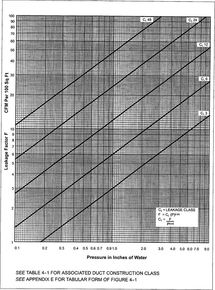
FIGURE 4-1 DUCT LEAKAGE CLASSIFICATION
4.2| DUCT CLASS | ½″, 1″, 2″ wg | 3″ wg | 4″, 6″, 10″ wg |
| SEAL CLASS | C | B | A |
| SEALING APPLICABLE | TRANSVERSE JOINTS ONLY | TRANSVERSE JOINTS AND SEAMS | JOINTS, SEAMS AND ALL WALL PENETRATIONS |
| LEAKAGE CLASS | |||
| RECTANGULAR METAL | 24 | 12 | 6 |
| ROUND METAL | 12 | 6 | 3 |
NOTES:
0.5″ wg maximum
0.6″ to 2″ wg maximum
1.1″ to 2″ wg maximum
2.1″ to 3″ wg maximum
3.1″ to 4″ wg maximum
4.1″ to 6″ wg maximum
6.1″ to 10″ wg maximum
Test apparatus shall consist of an airflow measuring device, flow producing unit, pressure indicating devices and accessories necessary to connect the metering system to the test specimen.
The contractor conducting tests shall arrange for or provide all temporary services, all test apparatus, all temporary seals and all qualified personnel necessary to conduct the specified testing.
Test apparatus shall be accurate within plus or minus 7.5% at the indicated flow rate and test pressure and shall have calibration data or a certificate signifying manufacture of the meter in conformance with the ASME Requirements for Fluid Meters. ASME qualified, orifice meters do not require calibration.
Unless otherwise specified, test apparatus shall be used as outlined in this section, as described in Section 3 and as recommended for good practice.
Typical construction and use of orifice meters is indicated in Figures 5-1 and 5-2. Typical orifice selections are shown in Figure 5-3.
The use of flow nozzles, venturi meters, laminar flow meters, rotameters, Pitot tube meters or other meters having equivalent accuracy and suitability is not prohibited by the references herein to orifice meters.
The recommended minimum thicknesses for orifice plates in tubes of various diameters are 1/16″ to 6″ diameter, 3/32″ to 12″ diameter and ⅛″ for larger diameters. Steel or stainless steel plate material is preferable. Plates shall be flat and have holes with square edges (90°) that are free of burrs. Orifice openings shall be centered in the meter tube. Plates shall be perpendicular to the flow path and shall be free of leaks at points of attachment.
Taps for static pressure indication across orifices shall be made with 1/16″ to ⅛″ diameter holes drilled neatly in the meter tube wall. The interior of the tube shall be smooth and free of projections at the drilled holes.
Pressure differential sensing instruments shall be readable to 0.05″ scale division for flow rates below 10 cfm or below 0.5″ wg differential. For higher flow scale divisions of 0.1″ are appropriate. U-tube manometers should not be used for readings less than 1″ of water.
Liquid for manometers shall have a specific gravity of 1 (as water) unless the scale is calibrated to read in inches of water contingent on use of a liquid of another specific gravity, in which case the associated gage fluid must be used.
The duct test pressure shall be sensed only from an opening in the duct.
The illustration of the flowmeter on test blower discharge does not preclude use of it on the suction side.
Instruments must be adjusted to zero reading before pressure is applied.
Airflow across a sharp edge orifice with standard air density of .075 lb/ft3 is calculated from

Where
| Q | = | air volume, cfm | |||
| K | = | coefficient of airflow from Table 5-1 or Appendix J | |||
| D | = | orifice diameter, inches (D2) | |||
| DP | = | Pressure drop across orifice, inches wg | |||
| D2/D1 | 0.70 | 0.60 | 0.50 | 0.40 | 0.30 |
| A2/A1 | 0.490 | 0.36 | 0.250 | 0.160 | 0.090 |
| K | 0.699 | 0.650 | 0.623 | 0.608 | 0.600 |
| Kp | 0.52 | 0.63 | 0.73 | 0.82 | 0.88 |

FIGURE 5-1 LEAKAGE TEST METER APPARATUS—FLANGE TAPS
5.2
FIGURE 5-2 LEAKAGE TEST METER APPARATUS—VENA CONTRACTA TAPS
5.3The ratio of orifice diameter D2 to meter tube interior diameter D1 is known as the Beta (β), or diameter ratio. It is normally selected in the range of 0.7 to 0.3. The orifice-to-tube area ratio (A2/A1) is an indication of the contraction of flow. Kp in Table 5-1 is the overall pressure loss that occurs from contracting and expanding the flow. Thus, the orifice causes a Kp × ΔP loss that affects blower capacity.
Select a flowmeter suitable for the leakage in the duct to be tested:
Precautions to be followed for test apparatus:
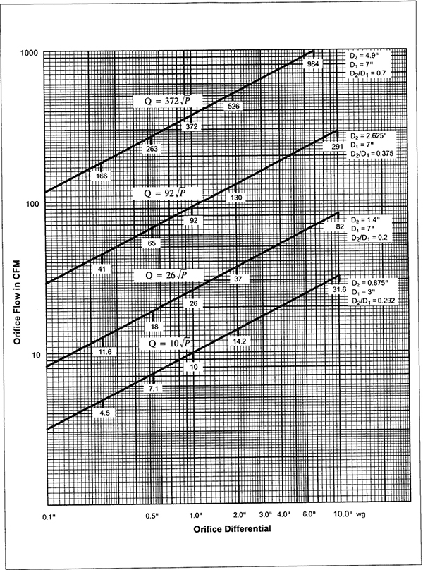
FIGURE 5-3 TYPICAL ORIFICE FLOW CURVES
5.5| AP in. wg | Orifice Size | ||
|---|---|---|---|
| 1.4* | 2.625* | 4.90* | |
| 0.02 | 57.1 | ||
| 0.04 | 18.7 | 78.8 | |
| 0.06 | 22.8 | 95.3 | |
| 0.08 | 26.2 | 109.2 | |
| 0.10 | 29.3 | 121.5 | |
| 0.12 | 32.1 | 132.6 | |
| 0.14 | 34.6 | 142.8 | |
| 0.16 | 37.0 | 152.3 | |
| 0.18 | 39.2 | 161.2 | |
| 0.20 | 41.3 | 169.6 | |
| 0.22 | 43.3 | 177.6 | |
| 0.24 | 45.2 | 185.2 | |
| 0.26 | 47.0 | 192.6 | |
| 0.28 | 48.8 | 199.6 | |
| 0.30 | 50.5 | 206.5 | |
| 0.32 | 52.1 | 213.0 | |
| 0.34 | 53.7 | 219.4 | |
| 0.36 | 55.3 | 225.6 | |
| 0.38 | 56.8 | 231.6 | |
| 0.40 | 58.3 | 237.5 | |
| 0.42 | 59.7 | 243.2 | |
| 0.44 | 61.1 | 248.8 | |
| 0.46 | 62.4 | 254.3 | |
| 0.48 | 63.8 | 259.6 | |
| 0.50 | 18.5 | 65.1 | 264.9 |
| 0.52 | 18.8 | 66.4 | 270.0 |
| 0.54 | 19.2 | 67.6 | 275.0 |
| 0.56 | 19.5 | 68.9 | 280.0 |
| 0.58 | 19.9 | 70.1 | 284.8 |
| 0.60 | 20.2 | 71.3 | 289.6 |
| 0.62 | 20.6 | 72.4 | 294.3 |
| 0.64 | 20.9 | 73.6 | 298.9 |
| 0.66 | 21,2 | 74.7 | 303.4 |
| 0.68 | 21.5 | 75.8 | 307.9 |
| 0.70 | 21.8 | 76.9 | 312.3 |
| 0.72 | 22.1 | 78.0 | 316.7 |
| 0.74 | 22.4 | 79.1 | 320.9 |
| 0.76 | 22.7 | 80.2 | 325.2 |
| 0.78 | 23.0 | 81.2 | 329.3 |
| 0.80 | 23.3 | 82.2 | 333.5 |
| 0.82 | 23.6 | 83.2 | 337.5 |
| 0.84 | 23.9 | 84.2 | 341.6 |
| 0.86 | 24.1 | 85.2 | 345.5 |
| 0.88 | 24.4 | 86.2 | 349.4 |
| 0.90 | 24.7 | 87.2 | 353.3 |
| 0.92 | 25.0 | 88.1 | 357.2 |
| 0.94 | 25.2 | 89.1 | 361.0 |
| 0.96 | 25.5 | 90.0 | 364.7 |
| 0.98 | 25.8 | 91.0 | 368.4 |
| 1.00 | 26.0 | 91.9 | 372.1 |
| 1.02 | 26.3 | 92.8 | 375.7 |
| 1.04 | 26.5 | 93.7 | 379.3 |
| 1.06 | 26.8 | 94.6 | 382.9 |
| 1.08 | 27.0 | 95.5 | 386.4 |
| 1.10 | 27.3 | 96.3 | 390.0 |
| 1.12 | 27.5 | 97.2 | 393.4 |
| 1.14 | 27.8 | 98.1 | 396.9 |
| 1.16 | 28.0 | 98.9 | 400.3 |
| 1.18 | 28.2 | 99.8 | 403.7 |
| 1.20 | 28.5 | 100.6 | 407.0 |
| 1.22 | 28.7 | 101.4 | 410.3 |
| 1.24 | 28.9 | 102.3 | 413.6 |
| 1.26 | 29.2 | 103.1 | 416.9 |
| 1.28 | 29.4 | 103.9 | 420.1 |
| 1.30 | 29.6 | 104.7 | 423.4 |
| 1.32 | 29.8 | 105.5 | 426.5 |
| 1.34 | 30.1 | 106.3 | 429.7 |
| 1.36 | 30.3 | 107.1 | 432.9 |
| 1.38 | 30.5 | 107.9 | 436.0 |
| 1.40 | 30.7 | 108.6 | 439.1 |
| 1.42 | 30.9 | 109.4 | 442.2 |
| 1.44 | 31.2 | 110.2 | 445.2 |
| 1.46 | 31.4 | 110.9 | 448.3 |
| 1.48 | 31.6 | 111.7 | 451.3 |
| 1.50 | 31.8 | 112.4 | 454.3 |
| 1.52 | 32.0 | 113.2 | 457.2 |
| 1.54 | 32.2 | 113.9 | 460.2 |
| 1.56 | 32.4 | 114.6 | 463.1 |
| 1.58 | 32.6 | 115.4 | 466.0 |
| 1.60 | 32.8 | 116.1 | 468.9 |
| 1.62 | 33.0 | 116.8 | 471.8 |
| 1.64 | 33.2 | 117.5 | 474.7 |
| 1.66 | 33.4 | 118.2 | 477.5 |
| 1.68 | 33.6 | 118.9 | 480.3 |
| 1.70 | 33.8 | 119.6 | 483.1 |
| 1.72 | 34.0 | 120.3 | 485.9 |
| 1.74 | 34.2 | 121.0 | 488.7 |
| 1.76 | 34.4 | 121.7 | 491.5 |
| 1.78 | 34.6 | 122.4 | 494.2 |
| 1.80 | 34.8 | 123.1 | 496.9 |
| 1.82 | 35.0 | 123.8 | 499.7 |
| 1.84 | 35.2 | 124.4 | 502.4 |
| 1.86 | 35.4 | 125.1 | 505.0 |
| 1.88 | 35.5 | 125.8 | 507.7 |
| 1.90 | 35.7 | 126.4 | 510.4 |
| 1.92 | 35.9 | 127.1 | 513.0 |
| 1.94 | 36.1 | 127.8 | 515.6 |
| 1.96 | 36.3 | 128.4 | 518.2 |
| 1.98 | 36.5 | 129.1 | 520.8 |
| 2.00 | 36.6 | 129.7 | 523.4 |
| 2.10 | 37.5 | 132.9 | 536.2 |
| 2.20 | 38.4 | 136.0 | 548.6 |
| 2.30 | 39.3 | 139.0 | 560.8 |
| 2.40 | 40.1 | 142.0 | 572.6 |
| 2.50 | 40.9 | 144.9 | 584.3 |
| 2.60 | 41.7 | 147.8 | 595.7 |
| 2.70 | 42.5 | 150.6 | 606.9 |
| 2.80 | 43.3 | 153.3 | 617.9 |
| 2.90 | 44.0 | 156.0 | 628.6 |
| 3.00 | 44.8 | 158.7 | 639.2 |
| 3.10 | 45.5 | 161.3 | 649.6 |
| 3.20 | 46.2 | 163.8 | 659.9 |
| 3.30 | 46.9 | 166.4 | 670.0 |
| 3.40 | 47.6 | 168.8 | 679.9 |
| 3.50 | 48.3 | 171.3 | 689.7 |
| 3.60 | 49.0 | 173.7 | 699.3 |
| 3.70 | 49.7 | 176.1 | 708.8 |
| 3.80 | 50.3 | 178.4 | 718.2 |
| 3.90 | 51.0 | 180.7 | 727.5 |
| 4.00 | 51.6 | 183.0 | 736.6 |
| 4.10 | 52.3 | 185.3 | 746 |
| 4.20 | 52.9 | 187.5 | 755 |
| 4.30 | 53.5 | 189.7 | 763 |
| 4.40 | 54.1 | 191.9 | 772 |
| 4.50 | 54.7 | 194.0 | 781 |
| 4.60 | 55.3 | 196.2 | 789 |
| 4.70 | 55.9 | 198.3 | 797 |
| 4.80 | 56.5 | 200.4 | 806 |
| 4.90 | 57.1 | 202.4 | 814 |
| 5.00 | 57.6 | 204.4 | 822 |
| 5.10 | 58.2 | 206.5 | 830 |
| 5.20 | 58.8 | 208.5 | 838 |
| 5.30 | 59.3 | 210.4 | 846 |
| 5.40 | 59.9 | 212.4 | 854 |
| 5.50 | 60.4 | 214.3 | 862 |
| 5.60 | 61.0 | 216.3 | 869 |
| 5.70 | 61.5 | 218.2 | 877 |
| 5.80 | 62.0 | 220.0 | 884 |
| 5.90 | 62.6 | 221.9 | 892 |
| 6.00 | 63.1 | 223.8 | 899 |
| 6.10 | 63.6 | 225.6 | 907 |
| 6.20 | 64.1 | 227.4 | 914 |
| 6.30 | 64.6 | 229.2 | 921 |
| 6.40 | 65.1 | 231.0 | 928 |
| 6.50 | 65.6 | 232.8 | 935 |
| 6.60 | 66.1 | 234.6 | 942 |
| 6.70 | 66.6 | 236.3 | 949 |
| 6.80 | 67.1 | 238.1 | 956 |
| 6.90 | 67.6 | 239.8 | 963 |
| 7.00 | 68.1 | 241.4 | 970 |
| 7.10 | 68.5 | 243.2 | 977 |
| 7.20 | 69.0 | 244.9 | 984 |
| 7.30 | 69.5 | 246.5 | 990 |
| 7.40 | 69.9 | 248.2 | 997 |
| 7.50 | 70.4 | 249.9 | 1003 |
| 7.60 | 70.9 | 251.5 | 1010 |
| 7.70 | 71.3 | 253.1 | 1017 |
| 7.80 | 71.8 | 254.7 | 1023 |
| 7.90 | 72.2 | 256.4 | 1029 |
| 8.00 | 72.7 | 257.9 | 1036 |
| 8.10 | 73.1 | 259.5 | 1042 |
| 8.20 | 73.6 | 261.1 | 1048 |
| 8.30 | 74.0 | 262.7 | 1055 |
| 8.40 | 74.5 | 264.2 | 1061 |
| 8.50 | 74.9 | 265.8 | 1067 |
| 8.60 | 75.3 | 267.3 | 1073 |
| 8.70 | 75.7 | 268.8 | 1079 |
| 8.80 | 76.2 | 270.4 | 1085 |
| 8.90 | 76.6 | 271.9 | 1091 |
| 9.00 | 77.0 | 273.4 | 1097 |
| 9.10 | 77.4 | 274.9 | 1103 |
| 9.20 | 77.9 | 276.4 | 1109 |
| 9.30 | 78.3 | 277.8 | 1115 |
| 9.40 | 78.7 | 279.3 | 1121 |
| 9.50 | 79.1 | 280.8 | 1127 |
| 9.60 | 79.5 | 282.2 | 1132 |
| 9.70 | 79.9 | 283.6 | 1138 |
| 9.80 | 80.3 | 285.1 | 1144 |
| 9.90 | 80.7 | 286.5 | 1150 |
| 10.00 | 81.1 | 287.9 | 1155 |
Based on 7″ Diameter Tube with Flange (Pipe) Taps
Although the table gives cfm to the nearest 0.1, test reports should list numbers rounded to the nearest cfm. Accuracy to the nearest 0.1 is not implied.
SCFM denotes air at standard conditions of 70°F and 0.075 lb/cf density.
Reprinted from Industrial Ventilation by the American Conference of Governmental Hygienists.
5.6 5.7 5.8When leakage tests are required, preparation for these should include the following:
When the designer has adequately analyzed the systems and clearly specified the test parameters the reporting procedure is relatively simple. As discussed in previous sections the following requirements should be clearly specified:
Test Pressure (equivalent to the duct construction pressure class is suggested).
Leakage Class (class selected from Table 4.1).
Amount of system to be tested (10%, 20%, 50%, all).
If the test pressure or leakage class has not been provided, see Appendix C and section 2.
Verification of compliance consists of testing sections of duct at the specified pressure level, finding the leakage in cfm and comparing this with the allowable amount associated with the leakage class. When several separate segments within the same system and pressure class are tested for compliance, the aggregate leakage should not exceed the allowable, even though the amount in one or more segments may somewhat exceed the cfm allowable indicated for each segment. In such case, to compensate, another segment would have to be tighter than required. If the duct is not in compliance refer to section 3.7 of the general procedures.
A suggested test summary report form is provided on page 6.2, and a sample of a completed report is shown on page 6.3. The orifice tube data entries can be eliminated if a different type of test apparatus is used. In such case record the type of meter on the test report.
Procedure for completing a report.
Test reports shall be submitted as required by the project documents.
6.1PROJECT NAME ______________ PROJECT NO. _____________ PAGE _____ OF _____
AIR DUCT LEAKAGE TEST SUMMARY
AIR SYSTEM ______________ LEAKAGE CLASS ______________
FAN CFM (Q)______________ SPECIFIED TEST PRESSURE (Pt) _____
DUCT CONSTRUCTION PRESSURE CLASS (Pc) ____
| DESIGN DATA | FIELD TEST DATA RECORD | ||||||||||
|---|---|---|---|---|---|---|---|---|---|---|---|
| SUBJECT DUCT | SURFAC AREA IN FT2 | ALLOWABLE LEAKAGE | DIAMETER | PRESSURE” W.G | DATE | PERFORMED BY | WITNESSED BY | ACTUAL CFM | |||
| FACTOR CFM/100 FT2 | CFM (TEST SECTION) | ORIFICE | TUBE | DUCT | ACROSS ORIFICE | ||||||
| TOTAL SYSTEM | **** | *** | ** | ***** | **** | **** | **** | ||||
| TEST SETION(S) | |||||||||||
PROJECT NAME Wall Street Towers PROJECT NO. 3432 PAGE _____ OF _____
AIR DUCT LEAKAGE TEST SUMMARY
AIR SYSTEM HVAC-2 LEAKAGE CLASS 3
FAN CFM (Q) 24,000 SPECIFIED TEST PRESSURE (Pt) 6”
DUCT CONSTRUCTION PRESSURE CLASS (Pc) 6”
| DESIGN DATA | FIELD TEST DATA RECORD | ||||||||||
|---|---|---|---|---|---|---|---|---|---|---|---|
| SUBJECT DUCT | SURFACE-AREA IN FT2 | ALLOWABLE LEAKAGE | DIAMETER | PRESSURE ” W.G | DATE | PERFORMED BY | WITNESSED BY | ACTUAL CFM | |||
| FACTOR CFM/100 FT2 | CFM (TEST SECTION) | ORIFICE | TUBE | DUCT | ACROSS ORIFICE | ||||||
| TOTAL SYSTEM | 9600 | **** | *** | ** | ***** | **** | **** | **** | |||
| TEST SETION(S) | |||||||||||
| RISERS | 840 | 9.6 | 81 | 2.625” | 7” | 6 | 0.6 | 3.7.85 | JRL | UNG | 71 |
| 3rd FL. MAIN | 560 | 9.6 | 54 | 1.4” | 7” | 6 | 3.2 | 3.13.85 | JRL | UNG | 46 |
| NORTH BRANCH | 410 | 9.6 | 39 | 1.4” | 7” | 6 | 3.5 | 4.16.85 | ABT | UNG | 48 |
| EAST BRANCH | 480 | 9.6 | 46 | 1.4” | 7” | 6 | 1.8 | 4.19.85 | ABT | UNG | 35 |
| TOTAL | 2290 | 220 | 200 | ||||||||
| (SEGMENTS TESTED) | |||||||||||
APPENDICES
6.5 6.6| LEAKAGE CLASS | FAN CFM PRORATED* PER S.F. | STATIC PRESSURE (IN WG) | |||||
|---|---|---|---|---|---|---|---|
| 1/2 | 1 | 2 | 3 | 4 | 6 | ||
| 48 | 2 | 15 | 24 | 38 | |||
| 2½ | 12 | 19 | 30 | ||||
| 3 | 10 | 16 | 25 | ||||
| 4 | 7.7 | 12 | 19 | ||||
| 5 | 6.1 | 9.6 | 15 | ||||
| 24 | 2 | 7.7 | 12 | 19 | |||
| 2 ½ | 6.1 | 9.6 | 15 | ||||
| 3 | 5.1 | 8.0 | 13 | ||||
| 4 | 3.8 | 6.0 | 9.4 | ||||
| 5 | 3.1 | 4.8 | 7.5 | ||||
| 12 | 2 | 3.8 | 6 | 9.4 | 12 | ||
| 2 ½ | 3.1 | 4.8 | 7.5 | 9.8 | |||
| 3 | 2.6 | 4.0 | 6.3 | 8.2 | |||
| 4 | 1.9 | 3.0 | 4.7 | 6.1 | |||
| 5 | 1.5 | 2.4 | 3.8 | 4.9 | |||
| 6 | 2 | 1.9 | 3 | 4.7 | 6.1 | 7.4 | 9.6 |
| 2½ | 1.5 | 2.4 | 3.8 | 4.9 | 5.9 | 7.7 | |
| 3 | 1.3 | 2.0 | 3.1 | 4.1 | 4.9 | 6.4 | |
| 4 | 1.0 | 1.5 | 2.4 | 3.1 | 3.7 | 4.8 | |
| 5 | 0.8 | 1.2 | 1.9 | 2.4 | 3.0 | 3.8 | |
| 3 | 2 | 1.0 | 1.5 | 2.4 | 3.1 | 3.7 | 4.8 |
| 2½ | 0.8 | 1.2 | 1.9 | 2.4 | 3.0 | 3.8 | |
| 3 | 0.6 | 1.0 | 1.6 | 2.0 | 2.5 | 3.2 | |
| 4 | 0.5 | 0.8 | 1.3 | 1.6 | 2.0 | 2.6 | |
| 5 | 0.4 | 0.6 | 0.9 | 1.2 | 1.5 | 1.9 | |
*TYPICALLY  WILL BE 2 TO 5 CFM/SQUARE FOOT.
% OF FLOW = LEAKAGE FACTOR (IN CFM/100 AT THE PRESSURE)
DIVIDED BY 
CLASS 48 IS AVERAGE UNSEALED RECTANGULAR DUCT. CLASS 24 AND LOWER ARE ANTICIPATED RESULTS FOR SEALED DUCTS.
A.1 A.2Since the system size and the impracticality of attempting to reach unrealistically low levels of leakage are such prominent considerations, the evaluation of leakage by the percentage method should be a secondary consideration. However, it is recognized that a percent of fan cfm or a percent of flow in a section of a system that passes through unconditioned space (considered as a heat loss or a heat gain) can be a useful parameter in energy conservation analysis. Leakage as a percent of flow entering one selected section of duct is not an adequate appraisal of the system performance. Five percent of the system flow is quite a different criteria than allowing 5% in each 100 ft of a 500 ft continuous run of duct. It should also be remembered that actual leakage will tend to be less than that appraised for the maximum pressure, because the average pressure under operating conditions will be less.
Leakage as a percent of flow has been related to leakage class and pressure in Appendix A. As Appendix A is studied, the significance of seal classes A, B, and C as applicable to duct pressure classes (see Table 4-1) must be understood. An example of the application of leakage classes to a duct system is provided to aid a realistic approach to the use of seal class, leakage class and percentage method analysis. While other parameters such as cubic contents (of duct interior) or lineal feet of joint might be used for leakage evaluation they are less practical and should not be used unless the square footage analysis has already been made.
SYSTEM DATA
Leakage Evaluation for Supply Duct in Figure 8-1, page 8-4 of the SMACNA HVAC Duct Design Manual
8000 cfm fan
½” wg duct construction class
320 l.f. of duct
2,074 ft2 duct

6.3 ft2 duct per l.f. of duct

622 cfm is 7.8% of 8000 cfm fan capacity.
Alternative Calculation (as in Appendix A)


NOTE: The difference (7.7 vs. 7.8) occurs because 3.9 is rounded from 3.857.
From Figure 4-1, 16 cfm/100 s.f. is read.

which is 4.1% of fan cfm.
Alternative method: 
From Figure 4-1, 7.5/100 × 2074 = 156 cfm or 1.94%
If 5% is allowed (i.e., 400 cfm) this is 
or 19.3 cfm/100 s.f. allowable;
Leakage class if 
The plan on page 8-5 of the duct design manual shows an access door, two volume dampers and a flexible connection (vibration isolation type); leakage allowance for these is prorated to duct surface.
B.1
FIGURE B-1 DUCT SYSTEM EXAMPLE
B.2SUGGESTED ANALYSIS WHEN DESIGNER IS NOT USING THE SMACNA CRITERIA, DOES NOT PROVIDE LEAKAGE CLASS OR TEST PRESSURE AND ONLY REQUIRES TESTING TO MEET A PERCENTAGE AS ALLOWABLE LEAKAGE.
When a leakage class is specified it is relatively simple to find the allowable leakage for a given test segment. However, when a total allowable leakage is expressed as a percent of total flow, it is somewhat more cumbersome to prorate the allowable leakage to any single test segment. A suggested method is as follows:
At this point the contractor may find it informative to relate the contract requirements to the leakage suggested in Table 4.1. This can be done as follows:

In this formula (F) is the leakage rate obtained in paragraph (3) above, and P is the test pressure.
Compare the numerical value of the leakage class obtained through this calculation with the suggested leakage classes for the type of duct construction and extent of sealing used. If the calculated value is below the value suggested in Table 4-1 the contractors should anticipate some difficulty in obtaining satisfactory test results. The greater the difference is, the greater the difficulty will be. Resolve the issue under sections 2.1(e) and 2.2(c) of the leakage test manual.
The duct will be constructed for some pressure class (or classes). It is not practical to include duct from two different construction classes in the same leakage test segment. Ducts should not be leak tested at pressures greater than the construction class.
C.1 C.2NOTICE TO DESIGNERS:
WHEN TESTS ARE DEEMED NECESSARY, A TEST OF A REPRESENTATIVE SAMPLE OF THE DUCT IS RECOMMENDED. IF SAMPLE IS DEFECTIVE, THE CONTRACTOR SHOULD REPAIR OR MODIFY THE CONSTRUCTION. IF RESULTS OF SAMPLE TEST ARE GOOD, CONTRACTOR CAN BE PERMITTED TO PROCEED WITHOUT FURTHER TESTING VISUAL INSPECTION AND EXAMINATION OF OPERATING CONDITIONS SHOULD SUFFICE TO JUSTIFY FAITH IN METHODS USED.
| DUCT CONSTRUCTION CLASS | LEAKAGE CLASS |
|---|---|
| 10″ wg | 3 |
| 6″ wg | 6 |
| 4″ wg | 6 |
| 3″ wg | 12 |
NOTE: See section 4 of the SMACNA Leakage Test Manual for normal classification.
| LEAKAGE CLASS (CL) | UNSEALED | |||||
|---|---|---|---|---|---|---|
| PRESSURE W.G. | CLASS | CLASS | CLASS | CLASS | CLASS | |
| P0.65 | P″ | 3 | 6 | 12 | 24 | 48 |
| 0.143 | 0.05 | 0.4 | 0.9 | 1.7 | 3.4 | 6.7 |
| 0.224 | 0.10 | 0.7 | 1.3 | 2.7 | 5.4 | 10.7 |
| 0.351 | 0.20 | 1.1 | 2.1 | 4.2 | 8.4 | 16.8 |
| 0.457 | 0.30 | 1.4 | 2.7 | 5.5 | 11.0 | 21.9 |
| 0.551 | 0.40 | 1.7 | 3.3 | 6.6 | 13.2 | 26.4 |
| 0.637 | 0.50 | 1.9 | 3.8 | 7.6 | 15.3 | 30.6 |
| 0.717 | 0.60 | 2.2 | 4.3 | 8.6 | 17.2 | 34.4 |
| 0.793 | 0.70 | 2.4 | 4.8 | 9.5 | 19.0 | 38.1 |
| 0.865 | 0.80 | 2.6 | 5.2 | 10.4 | 20.8 | 41.5 |
| 0.934 | 0.90 | 2.8 | 5.6 | 11.2 | 22.4 | 44.8 |
| 1 | 1 | 3 | 6 | 12 | 24 | 48 |
| 1.30 | 1.5 | 3.9 | 7.8 | 15.6 | 31.2 | 62.4 |
| 1.57 | 2.0 | 4.7 | 9.4 | 18.8 | 37.7 | 75.4 |
| 1.81 | 2.5 | 5.4 | 10.9 | 21.7 | 43.4 | 86.8 |
| 2.04 | 3.0 | 6.1 | 12.2 | 24.5 | 49.0 | 98.0 |
| 2.26 | 3.5 | 6.7 | 13.6 | 27.1 | 54.2 | 108.5 |
| 2.46 | 4.0 | 7.4 | 14.8 | 29.5 | 59.0 | 118.1 |
| 2.66 | 4.5 | 8.0 | 16.0 | |||
| 2.85 | 5.0 | 8.6 | 17.1 |
|
||
| 3.03 | 5.5 | 9.1 | 18.2 | |||
| 3.20 | 6.0 | 9.6 | 19.2 | |||
| 3.54 | 7.0 | 10.6 | 21.2 | |||
| 3.86 | 8.0 | 11.6 | 23.2 | |||
| 4.17 | 9.0 | 12.5 | 25.0 | |||
| 4.47 | 10.0 | 13.4 | 26.8 | |||
| 4.75 | 11.0 | 14.3 | 28.5 | |||
These factor may also be read from Figure 4-1.
See Table 4-1 for seal class and pressure class.
E.1 E.2| LEAKAGE RATE CFM/100 SFD | LEAK TEST RIG FLOW CAPACITY IN CFM | |||||||
|---|---|---|---|---|---|---|---|---|
| 25 | 50 | 100 | 150 | 200 | 250 | 300 | 400 | |
| 1 | 2,500 | 5,000 | 10,000 | 15,000 | 20,000 | 25,000 | 30,000 | 40,000 |
| 2 | 1,250 | 2,500 | 5,000 | 7,500 | 10,000 | 12,500 | 15,000 | 20,000 |
| 3 | 833 | 1,666 | 3,333 | 5,000 | 6,666 | 8,333 | 10,000 | 13,333 |
| 4 | 625 | 1,250 | 2,500 | 3,750 | 5,000 | 6,250 | 7,500 | 10,000 |
| 5 | 500 | 1,000 | 2,000 | 3,000 | 4,000 | 5,000 | 6,000 | 8,000 |
| 6 | 417 | 833 | 1,667 | 2,500 | 3,333 | 4,167 | 5,000 | 6,667 |
| 10 | 250 | 500 | 1,000 | 1,500 | 2,000 | 2,500 | 3,000 | 4,000 |
| 12 | 208 | 417 | 833 | 1,250 | 1,667 | 2,083 | 2,500 | 3,333 |
| 15 | 167 | 333 | 666 | 1,000 | 1,333 | 1,667 | 2,000 | 2,667 |
| 20 | 125 | 250 | 500 | 750 | 1,000 | 1,250 | 1,500 | 2,000 |
| 25 | 100 | 200 | 400 | 600 | 800 | 1,000 | 1,200 | 1,600 |
| 30 | 83 | 167 | 333 | 500 | 667 | 833 | 1,000 | 1,333 |
| 50 | 50 | 100 | 200 | 300 | 400 | 500 | 600 | 800 |
SFD IS DUCT SURFACE AREA IN SQUARE FEET
NOTE: The static pressure for the test must develop within the cfm range of the test rig; if it does not the leakage in the amount of duct tested is (probably) greater than the estimated amount.
F.1 F.2| DUCT DIMENSION (WIDTH) | |||||||||||||||||||||||
|---|---|---|---|---|---|---|---|---|---|---|---|---|---|---|---|---|---|---|---|---|---|---|---|
| 6″ | 8″ | 10″ | 12″ | 14″ | 16″ | 18″ | 20″ | 22″ | 24″ | 26″ | 28″ | 30″ | 36″ | 42″ | 48″ | 54″ | 60″ | 66″ | 72″ | 84″ | 96″ | 108″ | |
| 6″ | 2.00 | 2.33 | 2.67 | 3.00 | 3.33 | 3.67 | 4.00 | 4.33 | 4.67 | 5.00 | 5.33 | 5.67 | 6.00 | 7.00 | 8.00 | 9.00 | 10.00 | 11.00 | 12.00 | 13.00 | 15.00 | 17.00 | 19.00 |
| 8″ | 2.67 | 3.00 | 3.33 | 3.67 | 4.00 | 4.33 | 4.67 | 5.00 | 5.33 | 5.67 | 6.00 | 6.33 | 7.33 | 8.33 | 9.33 | 10.33 | 11.33 | 12.33 | 13.33 | 15.33 | 17.33 | 19.33 | |
| 10″ | 3.33 | 3.67 | 4.00 | 4.33 | 4.67 | 5.00 | 5.33 | 5.67 | 6.00 | 6.33 | 6.67 | 7.67 | 8.67 | 9.67 | 10.67 | 11.67 | 12.67 | 13.67 | 15.67 | 17.67 | 19.67 | ||
| 12″ | 4.00 | 4.33 | 4.67 | 5.00 | 5.33 | 5.67 | 6.00 | 6.33 | 6.67 | 7.00 | 8.00 | 9.00 | 10.00 | 11.00 | 12.00 | 13.00 | 14.00 | 16.00 | 18.00 | 20.00 | |||
| 14″ | 4.67 | 5.00 | 5.33 | 5.67 | 6.00 | 6.33 | 6.67 | 7.00 | 7.33 | 8.33 | 9.33 | 10.33 | 11.33 | 12.33 | 13.33 | 14.33 | 16.33 | 18.33 | 20.33 | ||||
| 16″ | 5.33 | 5.67 | 6.00 | 6.33 | 6.67 | 7.00 | 7.33 | 7.67 | 8.67 | 9.67 | 10.67 | 11.67 | 12.67 | 13.67 | 14.67 | 16.67 | 18.67 | 20.67 | |||||
| 18″ | 6.00 | 6.33 | 6.67 | 7.00 | 7.33 | 7.67 | 8.00 | 9.00 | 10.00 | 11.00 | 12.00 | 13.00 | 14.00 | 15.00 | 17.00 | 19.00 | 21.00 | ||||||
| 20″ | 6.67 | 7.00 | 7.33 | 7.67 | 8.00 | 8.33 | 9.33 | 10.33 | 11.33 | 12.33 | 13.33 | 14.33 | 15.33 | 17.33 | 19.33 | 21.33 | |||||||
| 22″ | 7.33 | 767 | 8.00 | 8.33 | 8.67 | 9.67 | 10.67 | 11.67 | 12.67 | 13.67 | 14.67 | 15.67 | 17.67 | 19.67 | 21.67 | ||||||||
| 24″ | 8.00 | 8.33 | 8.67 | 9.00 | 10.00 | 11.00 | 12.00 | 13.00 | 14.00 | 15.00 | 16.00 | 18.00 | 20.00 | 22.00 | |||||||||
| 26″ | 8.67 | 9.00 | 9.33 | 10.33 | 11.33 | 12.33 | 13.33 | 14.33 | 15.33 | 16.33 | 18.33 | 20.33 | 22.33 | ||||||||||
| 28″ | 9.33 | 9.67 | 10.67 | 11.67 | 12.67 | 13.67 | 14.67 | 15.67 | 16.67 | 18.67 | 20.67 | 22.67 | |||||||||||
| 30″ | DUCT DIMENSION (DEPTH) |
10.00 | 11.00 | 12.00 | 13.00 | 14.00 | 15.00 | 16.00 | 17.00 | 19.00 | 21.00 | 23.00 | |||||||||||
| 36″ | 12.00 | 13.00 | 14.00 | 15.00 | 16.00 | 17.00 | 18.00 | 20.00 | 22.00 | 24.00 | |||||||||||||
| 42″ | 14.00 | 15.00 | 16.00 | 17.00 | 18.00 | 19.00 | 21.00 | 23.00 | 25.00 | ||||||||||||||
| 48″ | 16.00 | 17.00 | 18.00 | 1900 | 20.00 | 22.00 | 24.00 | 26.00 | |||||||||||||||
| 54″ | 18.00 | 19.00 | 20.00 | 21.00 | 23.00 | 25.00 | 27.00 | ||||||||||||||||
| 60″ | 20.00 | 21.00 | 22.00 | 24.00 | 26.00 | 28.00 | |||||||||||||||||
| 66″ | 22.00 | 23.00 | 25.00 | 27.00 | 29.00 | ||||||||||||||||||
| 72″ | 24.00 | 26.00 | 28.00 | 30.00 | |||||||||||||||||||
| 84″ | 28.00 | 30.00 | 32.00 | ||||||||||||||||||||
| 96″ | 32.00 | 34.00 | |||||||||||||||||||||
| 108″ | 36.00 | ||||||||||||||||||||||
| Diameter Inches | Area | Circumference | ||
|---|---|---|---|---|
| Sq In | Sq Ft | In | Ft | |
| 1 | 0.7854 | 0.00545 | 3.142 | 0.2618 |
| 2 | 3.1416 | 0.0218 | 6.283 | 0.5236 |
| 3 | 7.0686 | 0.0491 | 9.425 | 0.7854 |
| 4 | 12.5664 | 0.0873 | 12.566 | 1.047 |
| 5 | 19.6350 | 0.1364 | 15.708 | 1.309 |
| 6 | 28.2743 | 0.1964 | 18.850 | 1.571 |
| 7 | 38.4845 | 0.2673 | 21.991 | 1.833 |
| 8 | 50.2655 | 0.3491 | 25.133 | 2.094 |
| 9 | 63.6173 | 0.4418 | 28.274 | 2.356 |
| 10 | 78.5398 | 0.5454 | 31.416 | 2.618 |
| 11 | 95.0332 | 0.6600 | 34.558 | 2.880 |
| 12 | 113.097 | 0.7854 | 37.699 | 3.142 |
| 13 | 132.732 | 0.9218 | 40.841 | 3.403 |
| 14 | 153.938 | 1.069 | 43.982 | 3.665 |
| 15 | 176.715 | 1.227 | 47.124 | 3.927 |
| 16 | 201.062 | 1.396 | 50.265 | 4.189 |
| 17 | 226.980 | 1.576 | 53.407 | 4.451 |
| 18 | 254.469 | 1.767 | 56.549 | 4.712 |
| 19 | 283.529 | 1.969 | 59.690 | 4.974 |
| 20 | 314.159 | 2.182 | 62.832 | 5.236 |
| 21 | 346.361 | 2.405 | 65.973 | 5.498 |
| 22 | 380.133 | 2.640 | 69.115 | 5.760 |
| 23 | 415.476 | 2.885 | 72.257 | 6.021 |
| 24 | 452.389 | 3.142 | 75.398 | 6.283 |
| 25 | 490.874 | 3.409 | 78.540 | 6.545 |
| 26 | 530.929 | 3.687 | 81.681 | 6.807 |
| 27 | 572.555 | 3.976 | 84.823 | 7.069 |
| 28 | 615.752 | 4.276 | 87.965 | 7.330 |
| 29 | 660.520 | 4.587 | 91.106 | 7.592 |
| 30 | 706.859 | 4.909 | 94.248 | 7.854 |
| 31 | 754.768 | 5.241 | 97.389 | 8.116 |
| 32 | 804.248 | 5.585 | 100.531 | 8.378 |
| 33 | 855.299 | 5.940 | 103.673 | 8.639 |
| 34 | 907.920 | 6.305 | 106.814 | 8.901 |
| 35 | 942.113 | 6.681 | 109.956 | 9.163 |
| 36 | 1017.88 | 7.069 | 113.097 | 9.425 |
| 37 | 1075.21 | 7.467 | 116.239 | 9.686 |
| 38 | 1134.11 | 7.876 | 119.381 | 9.948 |
| 39 | 1194.59 | 8.296 | 122.522 | 10.21 |
| 40 | 1256.54 | 8.727 | 125.66 | 10.47 |
| 41 | 1320.25 | 9.168 | 128.81 | 10.73 |
| 42 | 1385.44 | 9.621 | 131.95 | 10.99 |
| 43 | 1452.20 | 10.08 | 135.09 | 11.26 |
| 44 | 1520.53 | 10.56 | 138.23 | 11.52 |
| 45 | 1590.43 | 11.04 | 141.37 | 11.78 |
| 46 | 1661.90 | 11.54 | 144.51 | 12.04 |
| 47 | 1734.94 | 12.05 | 147.65 | 12.30 |
| 48 | 1809.56 | 12.51 | 150.80 | 12.57 |
| 49 | 1885.74 | 13.09 | 153.94 | 12.83 |
| 50 | 1963.50 | 13.64 | 157.08 | 13.09 |
| 51 | 2042.82 | 14.19 | 160.22 | 13.35 |
| 52 | 2123.72 | 14.75 | 163.36 | 13.61 |
| 53 | 2206.18 | 15.32 | 166.50 | 13.88 |
| 54 | 2290.22 | 15.90 | 169.65 | 14.14 |
| 55 | 2375.83 | 16.50 | 172.79 | 14.40 |
| 56 | 2463.01 | 17.10 | 175.93 | 14.66 |
| 57 | 2551.76 | 17.72 | 179.07 | 14.92 |
| 58 | 2642.08 | 18.35 | 182.21 | 15.18 |
| 59 | 2733.97 | 18.99 | 185.35 | 15.45 |
| 60 | 2827.43 | 19.63 | 188.50 | 15.71 |
| 61 | 2922.47 | 20.29 | 191.64 | 15.97 |
| 62 | 3019.07 | 20.97 | 194.78 | 16.23 |
| 63 | 3117.25 | 21.65 | 197.92 | 16.49 |
| 64 | 3216.99 | 22.34 | 201.06 | 16.76 |
| 65 | 3318.31 | 23.04 | 204.20 | 17.02 |
| 66 | 3421.19 | 23.76 | 207.35 | 17.28 |
| 67 | 3525.65 | 24.48 | 210.49 | 17.54 |
| 68 | 3631.68 | 25.22 | 213.63 | 17.80 |
| 69 | 3739.28 | 25.97 | 216.67 | 18.06 |
| 70 | 3848.45 | 26.73 | 219.91 | 18.33 |
| 71 | 3959.19 | 27.49 | 233.05 | 18.69 |
| 72 | 4071.50 | 28.27 | 226.19 | 18.85 |
| 73 | 4185.39 | 29.07 | 229.34 | 19.11 |
| 74 | 4300.84 | 29.87 | 232.48 | 19.37 |
| 75 | 4417.86 | 30.68 | 235.62 | 19.63 |
| 76 | 4536.46 | 31.50 | 238.76 | 19.90 |
| 77 | 4656.63 | 32.34 | 241.90 | 20.16 |
| 78 | 4778.36 | 33.18 | 245.04 | 20.42 |
| 79 | 4901.67 | 34.04 | 248.19 | 20.68 |
| 80 | 5026.55 | 34.91 | 251.33 | 20.94 |
| 81 | 5153.00 | 35.78 | 254.47 | 21.21 |
| 82 | 5281.02 | 36.67 | 257.61 | 21.47 |
| 83 | 5410.61 | 37.57 | 260.75 | 21.73 |
| 84 | 5541.77 | 38.48 | 263.89 | 21.99 |
| 85 | 5674.50 | 39.41 | 267.04 | 22.25 |
| 86 | 5808.80 | 40.34 | 270.18 | 22.51 |
| 87 | 5944.68 | 41.28 | 273.32 | 22.78 |
| 88 | 6082.12 | 42.24 | 276.46 | 23.04 |
| 89 | 6221.14 | 43.20 | 279.60 | 23.30 |
| 90 | 6361.73 | 44.18 | 282.74 | 23.56 |
| 91 | 6503.88 | 45.17 | 285.88 | 23.82 |
| 92 | 6647.61 | 46.16 | 289.03 | 24.09 |
| 93 | 6792.91 | 47.17 | 292.17 | 24.35 |
| 94 | 6939.78 | 48.19 | 295.31 | 24.61 |
| 95 | 7088.78 | 49.22 | 298.45 | 24.87 |
| 96 | 7238.23 | 50.27 | 301.59 | 25.13 |
| 97 | 7389.81 | 51.32 | 304.73 | 25.39 |
| 98 | 7542.96 | 52.38 | 307.88 | 25.66 |
| 99 | 7699.69 | 53.46 | 311.02 | 25.92 |
| 100 | 7853.98 | 54.54 | 314.16 | 26.18 |
The surface area (per linear foot) of flat oval duct can be calculated from 3.14D + 2L, where L is the flat span and D is the depth. The value 3.14D or πD may be read in the circumference column of the above table. The flat width is equal to the difference between the major and minor dimensions.
H.1 H.2The basic flow equation is Q = AV for which Q is in cfm, A is in ft2 and V is in fpm. Velocity pressure head  and velocity
  where g is the gravitational factor of 32.17 lb/ft-sec/sec. To use basic formula in inches of water gage pressure it is necessary to multiply the velocity head in feet by 12 in/ft and by the ratio of air density to water density
  . To use velocity in fpm divide by 3600 s2/m2.
Thus, 
and 
When 
Fluid flow texts indicate that for temperatures below 500° F thermal expansion effects in the orifice meter need not be accounted for. Also, for the normal range pressures in HVAC system testing, the effects of air compressibility are negligible. A combined coefficient K is used for various effects due to approach, contraction, discharge and pressure tap locations.
Standard airflow across a sharp edge orifice with ρ = 0.075 lb/ft3 is calculated from

For densities other than standard, the following equation can be used as a good approximation:

| where | Q = | air volume, cfm |
| K = | coefficient of air flow | |
| D = | orifice diameter, inches | |
| ΔP = | pressure drop across orifice, ″wg | |
| d = | density factor from Appendix K |
The coefficient K is affected by the Reynolds number, a dimensionless value expressing flow conditions in a duct. Appendix J relates Reynolds number, Beta ratio, and K. The following equation gives a simplified method of calculating Reynolds number for standard air:
R = 8.4 DV
| Where | R = | Reynolds number |
| D = | Orifice diameter, inches | |
| V = | Velocity of air through orifice, fpm |
The coefficient K is read from Appendix J for the type of meter taps used. It varies more below R values of 105 than for higher values. Some texts such as Fan Engineering, copyrighted by Buffalo Forge Co., use K coefficients for Reynolds number of 106 (with pipe diameter as the reference) as reasonably accurate for normal flow in 1½″ to 16″ diameter pipes, whether flange or vena contracta taps are used. Fisher and Porter Company reports in their Flowmeter Orifice Sizing Handbook that ASME publications and other research indicate that regardless of pipe size and standard orifice tap locations, only ±1% error is likely over a beta range of 0.12 to 0.72 if the equation for K is

The terms with β in this equation are relatively small and the practice of using K = 0.60 is fairly common. Flow approaching the orifice must be uniform to maintain accuracy. Straightening vanes or other flow straightening means must be used upstream. However, ASME and other texts point out that the basic orifice flow coefficients need modification for the effects of gas expansion if the pressure drop across the orifice is more than a few percent of the absolute pressure upstream of the orifice. Appendix K may be used to evaluate the effects of a gas expansion factor Y in terms of β the upstream pressure Pl, the ratio of specific heat
I.1at constant pressure to constant volume (k = 1.4 for air) and orifice pressure drop. The y factor would reduce the apparent flow by becoming a multiplier in the formula Q = KcYAV. The Y factor should be considered when determining the beta ratio to be used in a meter that is to be highly accurate.
Manometer scales are calibrated for fluids of specific density. Fluids with density corresponding to scale calibration must be used. Recalibration is not necessary. Densities of various manometer fluids are given in Appendix M.
The accuracy of the K coefficients in Figure 5-1 can be compared with those varying with Reynolds number in the following manner.
With 100 cfm in a 2.625″ diameter orifice

Or 
If  Figure 1 gives K = 0.61 and Figure 2 gives K = 0.615.
Observe that 0.623 from Table 5-1 is 102% of 0.61. With 30 cfm in a 1″ diameter orifice,

If  Figure 1 gives K = 0.605 and Figure 2 gives K = 0.61.
Table 5-1 (interpolated) gives K = 0.6024 which is 98.8% of 0.61.
Various authorities agree that orifice meters that are precisely built to conform to ASME specifications do not require calibration. In Chapter 9 of Industrial Ventilation, ACGIH discusses orifice calibration with a standard Pitot tube and states that orifices conforming to meters indicated in Table 5-2 of this manual do not require calibration. Otherwise, the nominal values for K that are given in Table 5-1 are deemed suitable for flow measurement under field conditions. Table 5-1 is usable for vena contracta taps at all D2/D1 ratios and for flange taps when D2/D1 is 0.50 or less. Vena contracta taps or flange taps are acceptable for Figure 5-3 except that  (with K = 0.711) may have 10% error with flange taps when Reynolds number is less than 105.
Where test apparatus fan capacity is marginal overall pressure loss through the orifice meter may contribute to difficulty in obtaining the required test pressure level in the duct. The overall loss in relation to the diameter ratio β is indicated in Table 5-1 and in Figure 1.
A test meter must have a fan that can produce the target cfm at a static pressure that is a combination of the duct test pressure plus other “system” losses. The required capacity of a leakage test meter should be examined in relation to the duct leakage classification chart. The orifice relates cfm to pressure according to Q = C × P0.5. Leakage class is a plot of Q = C × P0.65. However, the orifice capacity needs to relate only to one pressure level on the leakage class curve, the test pressure. An orifice conforming to  will, for example, have the capacity to register only 24 cfm at 6″ orifice differential. If the test is at 6 static pressure for Leakage Class 3 compliance, i.e., 9.6 cfm per 100 s.f., with 6″ orifice differential and 6″ duct test pressure, the meter could only indicate 24 cfm. However, the blower for the test apparatus would have to produce 24 cfm at 10″ to 12″ static. Observe that with a β ratio of 0.29, as in a 3″ tube with 7/8″ orifice, the meter loss is 88% of the orifice differential. Assuming that the duct leaked at Class 3 and the test apparatus could generate the static pressure to indicate 24 cfm, 250 square feet of duct (24/9.6 × 100 = 250) could be tested at one time. A larger meter, for example, Q = 26ΔP, could test 666 s.f. of duct (64/9.6 × 100) with 6″ ΔP. If the meter were used to test Class 24 duct at 1½″ static and it could not develop more than about 10″ orifice drop while maintaining 1 ½″ in the tested duct; the 32 cfm metered could only handle 32/31 × 100 or 103 s.f. of duct (unless the leakage
rate was below the allowable). Comparing Figure 5-3 with Figure 4-1 can facilitate testing. Excess fan pressure can be controlled with inlet dampers, bypass, variable speed motors or other means.

FIGURE I-1 RATIO OF OVER-ALL PRESSURE LOSS TO METERED DIFFERENTIAL VERSUS DIAMETER β
Reprinted from Handbook No. 10B900. Flowmeter Orifice Sizing. Fischer and Porter Co., with permission
Air density varies with barometric pressure, temperature, and the amount of moisture present. Moist air is less dense than dry air at a given temperature. At a barometric pressure of 29.92 in. Hg and 70° F dry air has a density of 0.07495 lb/ft3. At 60° F dry air is 0.764 lb/ft3. Federal agency documents define “standard atmosphere”; at sea level standard temperature is 59° F with 29.921 in. Hg barometric pressure. Industry documents define “standard air” in different ways. ASHRAE uses a standard value of 0.075 lb of dry air per cubic foot for 60° F at saturation and for 69° F dry at 14.7 psia. The ASHRAE Fundamentals Handbook chapter on duct design states that no corrections to their duct friction chart are needed for ±30° F from 70° F, elevations to 1500 ft and duct pressures from +20″ wg to −20″ wg These limits result in only ±5% variation. Comparable limits should be acceptable for field tests. Other variations can be observed in Appendix K.
Those who test air handling systems will occasionally be concerned with the designations ACFM and SCFM. The “A” refers to “actual”; the “S” refers to standard (CFM). Chapter 10 of the Industrial Ventilation Manual, published by ACGIH, defines three equivalent methods of calculating ACFM. The SCFM basis is 0.075 lb/ft3 at 70° F at sea level.
 where T is actual dry bulb air temperature in °F, moisture is negligible and pressure is less than ±20″ wg.
 where d is air density taken from psychrometric charts.
These evaluations are rarely applied on commercial projects but are common in the industrial sector. For example, outdoor air at 95° db and 75° wb has a humid air volume of 14.3 ft3/lb of dry air. The density is 0.07 lb/ft3. By formula b) above an actual flow measurement of 100 cfm would mean a standard airflow of 93.3 cfm.
For additional information on flowmeters see references in Appendix N.
I.3Various methods of leak testing are used for shafts, building compartments, door cracks, windows, curtain walls, critical ducts in safety related criteria zones in nuclear power plants and other circumstances. ASME/ANSI Standard N510, Testing of Nuclear Air-Cleaning Systems, covers requirements for field testing of engineered safety feature systems and high efficiency air cleaning systems. Bubble, spray DOP, liquid penetrant, pressure decay rate and other methods are found in N510. Several levels of tightness for ducts in contamination zones and other applications are addressed in N510 and also in ASME/ANSI Standard N509, Nuclear Power Plant Air-Cleaning Units and Components. Provisions in both of these documents are reviewed in the ERDA 76-21, Nuclear Air Cleaning Handbook, available from the U.S. Department of Commerce NTIS.
Tracer gas methods have been used frequently by researchers investigating the leakage in houses and commercial building compartments. NBS has used the method and numerous ASHRAE transactions report this method and fan pressurization methods. Transaction HI-85-03 No. 2 lists many of the references. ASHRAE Fundamentals Handbook Chapter 25, on ventilation and infiltration, reports leakage rates for various building elements. Key standards for such tests are:
ASTM E283, Rate of Air Leakage Through Exterior Windows, Curtain Walls, and Doors
ASTM E741, Measuring Air Leakage by the Tracer Dilution Method
ASTM E779, Measuring Air Leakage by the Fan Pressurization Method
ASTM E783, Field Measurement of Air Leakage Through Installed Exterior Windows and Doors
Measurement techniques, field studies, and the significance of infiltration are comprehensively reviewed in ASTM STP 719-1980, Building Air Change Rate and Infiltration Measurements.
Typical leakage rates for walls and floors of commercial buildings are reported in Design of Smoke Control Systems for Buildings, available from ASHRAE. This document has an extensive bibliography on stairwell, shaft, and building leakage. At the present it appears that insufficient knowledge exists about the leakage rates in ceilings, interior partitions and corridor construction to document rates for design purposes.
Damper leakage is lab tested by AMCA Standard 500. Several classifications of damper leakage are published in UL Standard 555S, Leakage Rated Dampers for Use in Smoke Control Systems. Higher integrity classifications of damper leakage are in ANSI N509.
Tests of HVAC systems and building compartments for smoke control performance may involve flow direction study, air change rate and leakage evaluation by means other than orifice meters.
I.4
FIGURE J-1 FLOW COEFFICIENTS K FOR SQUARE/EDGED ORIFICE PLATES AND VENA CONTRACTA TAPS IN SMOOTH PIPE

FIGURE J-2 FLOW COEFFICIENTS K FOR SQUARE/EDGED ORIFICE PLATES AND FLANGE TAPS IN SMOOTH PIPE
J.1 J.2| Altitude | (ft) | Sea Level | 1000 | 2000 | 3000 | 4000 | 5000 | 6000 | 7000 | 8000 | 9000 | 10,000 |
|---|---|---|---|---|---|---|---|---|---|---|---|---|
| Barometer | (in. Hg) | 29.92 | 28.86 | 27.82 | 26.82 | 25.84 | 24.90 | 23.98 | 23.09 | 22.22 | 21.39 | 20.58 |
| (in. wg) | 407.5 | 392.8 | 378.6 | 365.0 | 351.7 | 338.9 | 326.4 | 314.3 | 302.1 | 291.1 | 280.1 | |
| Air Temp, | −40° | 1.26 | 1.22 | 1.17 | 1.13 | 1.09 | 1.05 | 1.01 | 0.97 | 0.93 | 0.90 | 0.87 |
| °F | 0° | 1.15 | 1.11 | 1.07 | 1.03 | 0.99 | 0.95 | 0.91 | 0.89 | 0.85 | 0.82 | 0.79 |
| 40° | 1.06 | 1.02 | 0.99 | 0.95 | 0.92 | 0.88 | 0.85 | 0.82 | 0.79 | 0.76 | 0.73 | |
| 70° | 1.00 | 0.96 | 0.93 | 0.89 | 0.86 | 0.83 | 0.80 | 0.77 | 0.74 | 0.71 | 0.69 | |
| 100° | 0.95 | 0.92 | 0.88 | 0.85 | 0.81 | 0.78 | 0.75 | 0.73 | 0.70 | 0.68 | 0.65 | |
| 150° | 0.87 | 0.84 | 0.81 | 0.78 | 0.75 | 0.72 | 0.69 | 0.67 | 0.65 | 0.62 | 0.60 | |
| 200° | 0.80 | 0.77 | 0.74 | 0.71 | 0.69 | 0.66 | 0.64 | 0.62 | 0.60 | 0.57 | 0.55 | |
| 250° | 0.75 | 0.72 | 0.70 | 0.67 | 0.64 | 0.62 | 0.60 | 0.58 | 0.56 | 0.58 | 0.51 | |
| 300° | 0.70 | 0.67 | 0.65 | 0.62 | 0.60 | 0.58 | 0.56 | 0.54 | 0.52 | 0.50 | 0.48 | |
| 350° | 0.65 | 0.62 | 0.60 | 0.58 | 0.56 | 0.54 | 0.52 | 0.51 | 0.49 | 0.47 | 0.45 | |
| 400° | 0.62 | 0.60 | 0.57 | 0.55 | 0.53 | 0.51 | 0.49 | 0.48 | 0.46 | 0.44 | 0.42 | |
| 450° | 0.58 | 0.56 | 0.54 | 0.52 | 0.50 | 0.48 | 0.46 | 0.45 | 0.43 | 0.42 | 0.40 | |
| 500° | 0.55 | 0.53 | 0.51 | 0.49 | 0.47 | 0.45 | 0.44 | 0.43 | 0.41 | 0.39 | 0.38 | |
| 550° | 0.53 | 0.51 | 0.49 | 0.47 | 0.45 | 0.44 | 0.42 | 0.41 | 0.39 | 0.38 | 0.36 | |
| 600° | 0.50 | 0.48 | 0.46 | 0.45 | 0.43 | 0.41 | 0.40 | 0.39 | 0.37 | 0.35 | 0.34 | |
| 700° | 0.46 | 0.44 | 0.43 | 0.41 | 0.39 | 0.38 | 0.37 | 0.35 | 0.34 | 0.33 | 0.32 | |
| 800° | 0.42 | 0.40 | 0.39 | 0.37 | 0.36 | 0.35 | 0.33 | 0.32 | 0.31 | 0.30 | 0.29 | |
| 900° | 0.39 | 0.37 | 0.36 | 0.35 | 0.33 | 0.32 | 0.31 | 0.30 | 0.29 | 0.28 | 0.27 | |
| 1000° | 0.36 | 0.35 | 0.33 | 0.32 | 0.31 | 0.30 | 0.29 | 0.28 | 0.27 | 0.26 | 0.25 | |
| Standard Air Density, Sea Level, 70°F = 0.075 lb/cu ft at 29.92 in. Hg | ||||||||||||
Reprinted from Industrial Ventilation, by the American Conference of Governmental Industrial Hygienists, with permission.
K.1 K.2
FIGURE L-1 GAS EXPANSION FACTOR, Y, VERSUS ACOUSTIC RATION, ΔP/KP1
Reprinted from Handbook No. 10B900, Flowmeter Orifice Sizing, Fischer and Porter, Co., with permission.
L.1 L.2| Liquid | Specific Gravity 20/20 | Action with Water Vapor | Vapor Pressure at 68°F | Coefficient of Thermal Expansion | Melting Point deg F | Boiling Point deg F | Flash Point deg F | ||||
|---|---|---|---|---|---|---|---|---|---|---|---|
| per deg F × 106 | per deg C × 106 | Range deg F | |||||||||
| mm Hg | |||||||||||
| 1. | Ethyl Alcohol, C2H6O | 0.7939 | absorbs | 43.9 | 600 | 1080 | 50-86 | −179 | 173 | 55 | |
| 2. | Kerosine, 41 API at 60°F | 0.8200 60/60 | negligible | — | 480 | 864 | 30-100 | −20 | 300+ | 120 | |
| 3. | Ellison Gage Oil | 0.8340 60/60 | negligible | — | 466 | 839 | 30-100 | — | 300+ | 140 | |
| 4. | Benzene (Benzol), C6H6 | 0.8794 | negligible | 74.7 | 687 | 1237 | 68 | 42 | 176 | 12 | |
| 5. | Butyl Cellosolve C6H6 (Ethylene Glycol Monobutyl Ether) | 0.9019 | absorbs | 0.85 | −100 | 340 | 165 | ||||
| 6. | Water | 1.000 | — | 17.5 | 115 | 2070 | 68 | 32 | 212 | non-inflam. | |
| 7. | Alcohol Glycol | 1.000 | absorbs | — | 427 | 769 | 30-100 | −60 | 173 | 70 | |
| 8. | Carbitol, C6H14O3 (Diethylene Glycol Monoethly Ether) | 1.024-30 | absorbs | −76 | 202 | 210 | |||||
| 9. | n-Butyl Phthalate, C16H22O4 | 1.0477 | negligible | 10-4 | 433 | 780 | − | −31 | 644 | 340 | |
| 10. | Ethylene Glycol (Glycol), C2H6O2 | 1.1155 20/4 | absorbs slowly | 0.09 | 354 | 638 | 68 | +0.8 | 387 | 241 | |
| 11. | Halowax Oil | 1.19-1.25 | — | 0.3-50°C | 367 | 660 | — | −24−2 | 203 | ||
| 12. | Glycerine (Glycerol), C3HgO3 | 1.260 20/4 | absorbs | low | 281 | 505 | 68 | 64 | 554 | 320 | |
| 13. | o-Dibromobenzene, C6H4Br2 | 1.956 20/4 | negligible | — | 432 | 778 | 30-100 | 35.2 | 430 | 150+ | |
| 14. | 1, 1-Dibromoethane, C6H4Br2 | 2.089 20/4 | negligible | 34.7 | 532 | 958 | 30-100 | 40 | 230 | 75+ | |
| 15. | Acetylene tetrabromide (Tetrabromoethane), C6H2Br4 | 2.964 20/4 | absorbs slightly | — | 370 | 660 | — | −4 | — | non-inflam. | |
| 16. | Mercury | 13.570 | negligible | 0.0012 | 101 | 181.8 | −20 to 250 | −38 | 679 | non-inflam. | |
Reprinted by permission. Copyright © Instrument Society of America 1978. From ISA Recommended Practice RP2.1—Manometer Tables
M.1 M.2ACGIH, American Conference of Governmental Industrial Hygienists, Lansing, MI
AGA, American Gas Association, Arlington, VA
ANSI, American National Standards Institute, New York, NY
APCA, Air Pollution Control Association, Pittsburgh, PA
API, American Petroleum Institute, Washington, DC
ASHRAE, American Society of Heating, Refrigerating and Air-Conditioning Engineers, Atlanta, GA
ASME, American Society of Mechanical Engineers, New York, NY
See building element leak test references and instrumentation in Appendix I.
N.1 N.2