
In order to promote public education and public safety, equal justice for all, a better informed citizenry, the rule of law, world trade and world peace, this legal document is hereby made available on a noncommercial basis, as it is the right of all humans to know and speak the laws that govern them.
SECOND EDITION – 1995
With
Addendum No. 1 November 1997
SHEET METAL AND AIR CONDITIONING CONTRACTORS’
NATIONAL ASSOCIATION, INC.
4201 Lafayette Center Drive
Chantilly, VA 20151–1209
HVAC DUCT
CONSTRUCTION STANDARDS
METAL AND FLEXIBLE
COPYRIGHT©1998
All Rights Reserved
by
SHEET METAL AND AIR CONDITIONING CONTRACTORS’
NATIONAL ASSOCIATION, INC.
4201 Lafayette Center Drive
Chantilly, VA 20151–1209
Printed in the U.S.A.
FIRST EDITION – 1985
SECOND EDITION – 1985
Second Printing – May 1996
Third Printing – July 1997
Fourth Printing – November 1998
Except as allowed in the Notice to Users and in certain licensing contracts, no part of this book may be reproduced, stored in a retrievable system, or transmitted, in any form or by any means, electronic, mechanical, photocopying, recording, or otherwise, without the prior written permission of the publisher.
iiThis Second Edition of the SMACNA commercial metal and flexible duct construction standards is another in a long line dating from the 1950s. A quick overview of the changes is provided in the front of this manual. Meanwhile, a Committee has already begun work on what will be either addenda or a new edition. Subjects being investigated are ribbed round duct, fatique testing of tie rodded metal, new flat oval duct standards, duct liner pin lengths, more double wall casings, sealant specifications and more performance specifications for joints and reinforcements. And, indirectly related to these standards, significant progress is being made by major mechanical code writing agencies in developing one uniform, consensus-supported code for the entire nation.
SMACNA expresses appreciation to the many who have offered suggestions for constructive improvement in the fabrication and installation of duct systems. Suggestions for future improvement are welcome. Special thanks is given to those who volunteered their time, gave their special knowledge and struggled with development of a consensus that would reflect the needs of a diversified industry. Although standardization intrinsically involves selection, no intention of discrimination against the use of any product or method that would serve a designer’s need equally or better exists.
Sheet Metal and Air Conditioning
Contractors’ National Association
HVAC DUCT CONSTRUCTION STANDARDS COMMITTEE
Ronald Rodgers, Chairman
J. B. Rodgers Mechanical Contractors
Phoenix, AZ
Seymore Cohen
Knecht, Inc.
Camden NJ
Dick Hoffa
Corn States Metal Fabricators, Inc.
West Des Moine, IA
Ronald Palmerick
AABCO Sheet Metal
Brooklyn, NY
Les Santeler
Climatemp, Inc.
Chicago, IL
John H. Stratton, Staff
SMACNA
Chantilly, VA
FORMER COMMITTEE MEMBERS* AND
OTHER CONTRIBUTORS TO THE SECOND EDITION
Michael Mamayek*, Chairman 1992-1993
Illingworth Corporation
Milwaukee, WI
Andrew Boniface*, Chairman 1989-1991
Bonland Industries, Inc.
Wayne, NJ
H. Andrew Kimmel*, Chairman 1988
E. W. Ensroth Co.
Warren, MI
Robert S. Deeds*, Chairman 1986-1987
METCO, Inc.
Salt Lake City, UT
Norman T. R. Heathorn*
N. B. Heathorn, Inc.
Oakland, CA
Gerald D. Hermanson*
Hermanson Corporation
Renton, WA
George J. Thomas, Jr.*
Thomas Roofing & Sheet Metal Co., Inc.
Atlantic City, NJ
Guillermo (“Bill”) Navas, Staff
SMACNA
Chantilly, VA
SPIRAL DUCT TASK FORCE
Ronald Rodgers, Chairman
Phoenix, AZ
Phillip Gillespie
Indianapolis, IN
Richard Graves
Houston, TX
Spence O’Brien
Whitter, CA
Robert Seiden
Pittsburgh, PA
SMACNA Technical Manuals & Standards
| Order # | Title |
|---|---|
| 1208 | HVAC Systems-Duct Design, 3rd Ed., 1990 |
| 1169 | HVAC Duct Design Home Study Course, 1st Ed., 1992 |
| 1039 | Duct Research Destroys Design Myths, 1987 Video, 24 minutes, VHS |
| 1052 | Duct System Calculator, 1988 (Circle one) Imperial Metric (1065) |
| 1079 | Ducted Electric Heat Guide for Air Handling Systems, 2nd Ed., 1994 |
| 1195 | HVAC Systems-Application, 1st Ed., 1986 |
| 1221 | HVAC Systems-Testing, Adjusting & Balancing, 2nd Ed., 1993 |
| 1234 | Indoor Air Quality Manual, 2nd Ed., 1993 |
| 1286 | Fire, Smoke & Radiation Damper Install. Guide for HVAC Systems, 4th Ed., 1992] |
| 1156 | HVAC Duct Construction Standards-Metal & Flexible, 2nd Ed., 1995 |
| 1143 | HVAC Air Duct Leakage Test Manual, 1st Ed., 1985 |
| 1117 | Fibrous Glass Duct Construction Standards, 6th Ed., 1992 |
| 1247 | Installation Standards for Residential Htg, & A/C Systems, 6th Ed., 1988 |
| 1182 | HVAC Duct Systems Inspection Guide, 1st Ed., 1989 |
| 1325 | Round Industrial Duct Construction Standards, 1st Ed., 1977 |
| 1299 | Rectangular Industrial Duct Construction Standards, 1st Ed., 1980 |
| 1378 | Thermoplastic Duct (PVC) Construction Manual, 2nd Ed., 1994 |
| 1338 | Seismic Restraint Manual, 1st Ed., 1991 (w/Appendix E, 1993) |
| 1130 | Managers’ Guide for Welding, 2nd Ed., 1993 |
Duct Systems Design
ASHRAE Handbook—Fundamentals and Systems and Equipment Volumes
ASHRAE—Principles of HVAC
ASHRAE Standard 62—Ventilation for Acceptable Indoor Air Quality
ASHRAE/IES Standard 90.1—Energy Efficient Design of New Buildings (Except Low Rise Residential Buildings)
Model Energy Code of the Council of American Building Officials (CABO)
Local Mechanical Codes
Corrosion
ASM International—Handbook of Corrosion Data (Metals)
Corrosion Resistant Materials Handbook (Metal and Non-Metals), NOYES DATA CORPORATION
NACE Catalog of Publications
Insulation
ASHRAE—Handbooks
ASHRAE—A Practical Guide to Noise and Vibration Control in HVAC Systems
MICA—National Commercial and Industrial Insulation Standards, Endorsed by NIAC
Structural Handbooks
AISI Cold-Formed Steel Design Manual
AISI Steel Products Manuals
AISI Design of Light Gage Cold-Formed Stainless Steel Structural Members
Cold-Formed Steel Structures—Design, Analysis and Construction, McGraw-Hill Publisher, Wei-Wen Yu, Author
AISC Manual of Steel Construction
MFMA Guidelines for the Use of Metal Framing (Strut Channel)
AA Specifications for Aluminum Structures
AA Engineering Data for Aluminum Structures
ASCE Standard 7, Minimum Design Loads for Buildings and Other Structures
FOOTNOTE: Associations whose acronyms are used in texts are:
AA—Aluminum Association
ACGIH—American Conference of Governmental Industrial Hygienists
ACCA—Air Conditioning Contractors of America
ADC—Air Diffusion Council
AISC—American Institute of Steel Construction
AISI—American Iron and Steel Institute
ASCE—American Society of Civil Engineers
ASHRAE—American Society of Heating, Refrigeration and Air Conditioning Engineers
ASTM—American Society for Testing and Materials
FHA—Federal Housing Administration
MFMA—Metal Framing Manufacturers Association
MICA—Midwest Insulation Contractors Association
NACE—National Association of Corrosion Engineers
NFPA—National Fire Protection Association
NAIMA—North American Insulation Manufacturers Association
NIAC—National Insulation and Abatement Contractors
UL—Underwriters Laboratories
Flexible Duct
UL Standard 181, for Factory-Made Duct Materials and Air Duct Connectors
UL Fire Resistance Directory
UL Gas and Oil Equipment Directory
NFPA Standard 90A
ADC Flexible Duct Performance & Installation Standards
ADC Standard FD-72R1 (Thermal, Friction Loss, Acoustical and Leakage Performance)
ASTM E 477 (Acoustical Performance)
ASTM E 96, Water Vapor Transmission of Materials in Sheet Form
Duct Liner
NFPA Standard 90A—Installation of Air Conditioning and Ventilating Systems
NFPA Standard 90B—Installation of Residence Type Warm Air Heating and Air Conditioning Systems
ASTM Standard C 1071, Standard Specifications for Thermal and Acoustical Insulation (Mineral Fiber, Duct Lining Material)
ASTM C 167—Thickness and Density of Blanket- or Batt-Type Thermal Insulating Materials
ASTM 553—Mineral Fiber Blanket and Felt Insulation (Moisture Absorption)
ASTM E 84—Test for Surface Burning Characteristics of Building Materials
ASTM C 423—Sound Absorption of Acoustical Materials in Reverberation Rooms
ASTM C 916—Specification for Adhesives for Duct Thermal Insulation (Flammability, smoke development, bond strength, flash point, moisture and temperature effects, edge burning characteristics)
ASHRAE Handbook—Applications Volume (Sound and Vibration Control)
ACGIH—Threshold Limit Values
Mil Spec A-3316B—Insulation Adhesives
NAIMA—Fibrous Glass Duct Liner Standard
Underground Duct
Ducts in Concrete Slabs or Under Slabs
References for Galvanized Steel in Soils
For loads on ditch conduits the following references are useful:
This document or publication is prepared for voluntary acceptance and use within the limitations of application defined herein, and otherwise as those adopting it or applying it deem appropriate. It is not a safety standard. Its application for a specific project is contingent on a designer or other authority defining a specific use. SMACNA has no power or authority to police or enforce compliance with the contents of this document or publication and it has no role in any representations by other parties that specific components are, in fact, in compliance with it.
The Association may, from time to time, issue formal interpretations or interim amendments, which can be of significance between successive editions.
SMACNA encourages technological development in the interest of improving the industry for the public benefit. SMACNA, does not, however, endorse individual manufacturers or products.
A formal interpretation of the literal text herein or the intent of the technical committee associated with the document or publication is obtainable only on the basis of written petition, addressed to the committee and sent to the Association’s national office in Chantilly, Virginia, and subsequent receipt of a written response signifying the approval of the chairman of the committee. In the event that the petitioner has a substantive disagreement with the interpretation, an appeal may be filed with the Technical Resources Committee which has technical oversight responsibility. The request must pertain to a specifically identified portion of the document that does not involve published text which provides the requested information. In considering such requests, the Association will not review or judge products or components as being in compliance with the document or publication. Oral and written interpretations otherwise obtained from anyone affiliated with the Association are unofficial. This procedures does not prevent any committee chairman, member of the committee, or staff liaison from expressing an opinion on a provision within the document, provided that such person clearly states that the opinion is personal and does not represent an official act of the association in any way, and it should not be relied on as such. The Board of Directors of SMACNA shall have final authority for interpretation of this standard with such rules or procedures as they may adopt for processing same.
Any Standards contained in this publication were developed using reliable engineering principles and research plus consultation with, and information obtained from, manufacturers, users, testing laboratories, and others having specialized experience. They are subject to revision as further experience and investigation may show is necessary or desirable. Construction and products that comply with these Standards will not necessarily be acceptable if, when examined and tested, they are found to have other features which impair the result contemplated by these requirements. The Sheet Metal and Air Conditioning Contractors’ National Association and other contributors assume no responsibility and accept no liability for the application of the principles or techniques contained in this publication. Authorities considering adoption of any standards contained herein should review all federal, state, local and contract regulations applicable to specific installations.
Nonexclusive, royalty-free permission is granted to government and private sector specifying authorities to reproduce only any construction details found herein in their specifications and contract drawings prepared for receipt of bids on new construction and renovation work within the Untied States and its territories, provided that the material copied is unaltered in substance and that the reproducer assumes all liability for the specific application, including errors in reproduction.
The SMACNA logo is registered as a membership identification mark. The Association prescribes acceptable use of the logo and expressly forbids the use of it to represent anything other than possession of membership. Possession of membership and use of the logo in no way constitutes or reflects SMACNA approval of any product, method, or component. Furthermore, compliance of any such item with standards published or recognized by SMACNA is not indicated by presence of the logo.
vi| COPYRIGHT NOTICE | II | ||
| FOREWORD | III | ||
| HVAC DUCT CONSTRUCTION STANDARDS COMMITTEE | IV | ||
| REFERENCES | V | ||
| NOTICE OF USERS | VI | ||
| TABLE OF CONTENTS | VII | ||
| LIST OF EDITION CHANGES | XII | ||
| MODEL PROJECT SPECIFICATION | XIII | ||
| CHAPTER 1 INTRODUCTION TO BASIC CONSTRUCTION | |||
| SYMBOLS FOR VENTILATION AND AIR CONDITIONING | 1.1 | ||
| 1.1 | DUCT SYSTEMS DESIGN | 1.3 | |
| 1.2 | GENERAL PERFORMANCE REQUIREMENT FOR ALL AIR DUCTS | 1.3 | |
| 1.3 | PRESSURE-VELOCITY CLASSIFICATION | 1.4 | |
| 1.4 | SCOPE | 1.4 | |
| 1.5 | REINFORCEMENT ARRANGEMENTS | 1.4 | |
| DUCT PRESSURE CLASS DESIGNATION | FIGURE 1-1 | 1.5 | |
| PRESSURE CLASSIFICATION FOR DUCTWORK | TABLE 1-1 | 1.6 | |
| STATIC PRESSURE | TABLE 1-1S | 1.6 | |
| 1.6 | DUCT CONSTRUCTION AND INSTALLATION STANDARDS | 1.8 | |
| STANDARD DUCT SEALING REQUIREMENTS | TABLE 1-2 | 1.9 | |
| 1.7 | DUCT SEALING COMMENTARY | 1.10 | |
| 1.8 | INTRODUCTION TO THE RECTANGULAR DUCT CONSTRUCTION SCHEDULES | 1.12 | |
| READING GUIDE SUMMARY | 1.14 | ||
| 1.9 | RECTANGULAR DUCT REINFORCEMENT | 1.16 | |
| 1/2″ W.G. RECTANGULAR DUCT REINFORCEMENT | TABLE 1-3 | 1.18 | |
| 1″ W.G. RECTANGULAR DUCT REINFORCEMENT | TABLE 1-4 | 1.20 | |
| 2″ W.G. RECTANGULAR DUCT REINFORCEMENT | TABLE 1-5 | 1.22 | |
| 3″ W.G. RECTANGULAR DUCT REINFORCEMENT | TABLE 1-6 | 1.24 | |
| 4″ W.G. RECTANGULAR DUCT REINFORCEMENT | TABLE 1-7 | 1.26 | |
| 6″ W.G. RECTANGULAR DUCT REINFORCEMENT | TABLE 1-8 | 1.28 | |
| 10″ W.G. RECTANGULAR DUCT REINFORCEMENT | TABLE 1-9 | 1.23 | |
| INTERMEDIATE REINFORCEMENT | TABLE 1-10 | 1.32 | |
| TRANSVERSE JOINT REINFORCEMENT | TABLE 1-11 | 1.34 | |
| TRANSVERSE JOINT REINFORCEMENT | TABLE 1-12 | 1.36 | |
| TRANSVERSE JOINT REINFORCEMENT | TABLE 1-13 | 1.38 | |
| 1.10 | TIE ROD INSTALLATIONS | 1.40 | |
| 1.11 | COMMENTARY | 1.41 | |
| TIE ROD ATTACHMENTS | FIGURE 1-2 | 1.42 | |
| TIE ROD ATTACHMENTS | FIGURE 1-3 | 1.43 | |
| INTERNAL TIE ROD DESIGN LOAD IN POUNDS | TABLE 1-14 | 1.44 | |
| INTERNAL TIE ROD SIZE (+) PRESSURE | TABLE 1-15 | 1.46 | |
| INTERNAL TIE ROD SIZE (–) PRESSURE | TABLE 1-16 | 1.48 | |
| INTERNAL RC CONDUIT SIZE (–) PRESSURE | TABLE 1-17 | 1.50 | |
| INTERNAL EMT CONDUIT SIZE (–) PRESSURE | TABLE 1-18 | 1.52 | |
| STEEL PIPE SIZE (–) PRESSURE | TABLE 1-19 | 1.54 | |
| ALLOWABLE LOAD FOR ANGLES AS COLUMNS WITH MAXIMUM UNBRACED LENGTH L | TABLE 1-20 | 1.56 | |
| 1.12 | COMMENTARY ON ALUMINUM DUCT | 1.58 | |
| RECTANGULAR ALUMINUM DUCT ADAPT FROM 3″ W.G. (750 PA) OR LOWER | TABLES 1-21, 1-22, 1-23 | 1.59 | |
| TRANSVERSE (GIRTH) JOINTS | FIGURE 1-4 | 1.61 | |
| 1.13 | TRANSVERSE JOINTS FOR RECTANGULAR DUCT | 1.62 vii | |
| 1.14 | NOTES FOR | FIGURE 1-4 | 1.63 |
| 1.15 | COMMENTS | 1.64 | |
| SPECIAL JOINT PROFILES | FIGURE 1-4A | 1.65 | |
| 1.16 | LONGITUDINAL SEAM FOR RECTANGULAR DUCT | 1.66 | |
| 1.17 | NOTES FOR | FIGURE 1-5 | 1.67 |
| LONGITUDINAL SEAMS-RECT. DUCT | FIGURE 1-5 | 1.66 | |
| INSIDE STANDING SEAM-LONGITUDINAL-2″ W.G (500 PA) MAXIMUM | FIGURE 1-6 | 1.68 | |
| UNREINFORCED DUCT (WALL THICKNESS) | TABLE 1-24 | 1.69 | |
| T-1 FLAT DRIVE JOINT ACCEPTED AS REINFORCEMENT | TABLE 1-25 | 1.71 | |
| UNREINFORCED DUCT | FIGURE 1-7 | 1.73 | |
| CROSSBROKEN AND BEADED DUCT | FIGURE 1-8 | 1.74 | |
| DUCT REINFORCED ON TWO SIDES | FIGURE 1-9 | 1.75 | |
| DUCT REINFORCED ON ALL SIDES | FIGURE 1-10 | 1.76 | |
| REINFORCEMENT ATTACHMENT | FIGURE 1-11 | 1.77 | |
| DUCT OVER 120″ (3048 MM) WIDE | FIGURE 1-12 | 1.78 | |
| CORNER CLOSURES-SLIPS AND DRIVES | FIGURE 1-13 | 1.79 | |
| CORNER CLOSURES-FLANGES T-21 & T-22 | FIGURE 1-14 | 1.80 | |
| CORNER CLOSURES-FLANGES T-24 & T-25 | FIGURE 1-15 | 1.81 | |
| CORNER CLOSURES-STANDING SEAMS | FIGURE 1-16 | 1.82 | |
| CHAPTER 2 FITTINGS AND OTHER CONSTRUCTION | |||
| 2.1 | REQUIREMENTS | 2.1 | |
| TYPICAL SUPPLY OR RETURN DUCT | FIGURE 2-1 | 2.2 | |
| RECTANGULAR ELBOWS | FIGURE 2-2 | 2.3 | |
| RECTANGULAR ELBOWS | FIGURE 2-2 | 2.4 | |
| VANES AND VANE RUNNERS | FIGURE 2-3 | 2.5 | |
| VANE SUPPORT IN ELBOWS | FIGURE 2-4 | 2.6 | |
| DIVIDED FLOW BRANCHES | FIGURE 2-5 | 2.7 | |
| BRANCH CONNECTIONS | FIGURE 2-6 | 2.8 | |
| OFFSETS AND TRANSITIONS | FIGURE 2-7 | 2.9 | |
| OBSTRUCTIONS | FIGURE 2-8 | 2.10 | |
| REMOTE HEATING AND COOLING COIL INSTALLATIONS | FIGURE 2-9 | 2.11 | |
| DUCT ACCESS DOORS AND PANELS | FIGURE 2-10 | 2.12 | |
| ACCESS DOORS-ROUND DUCT | FIGURE 2-11 | 2.14 | |
| 2.2 | VOLUME DAMPERS | 2.15 | |
| 2.3 | NOTES FOR | FIGURES 2-12 AND 2-13 | 2.15 |
| 2.4 | COMMENTARY | 2.15 | |
| VOLUME DAMPERS-SINGLE BLADE TYPE | FIGURE 2-12 | 2.16 | |
| MULTIBLADE VOLUME DAMPERS | FIGURE 2-13 | 2.17 | |
| GRILLE AND REGISTER CONNECTIONS | FIGURE 2-14 | 2.18 | |
| CEILING DIFFUSER BRANCH DUCTS | FIGURE 2-15 | 2.19 | |
| LINEAR DIFFUSER PLENUM | FIGURE 2-16 | 2.20 | |
| FLEXIBLE CONNECTIONS AT FAN | FIGURE 2-17 | 2.21 | |
| DISHWASHER VAPOR EXHAUST | FIGURE 2-18 | 2.22 | |
| 2.5 | HOODS | 2.23 | |
| FLEXIBLE DUCT LINER INSTALLATION | FIGURE 2-19 | 2.24 | |
| 2.6 | INSTALLATION STANDARDS FOR RECTANGULAR DUCTS USING FLEXIBLE LINER | 2.25 | |
| 2.7 | COMMENTARY | 2.26 | |
| LINER FASTENERS | FIGURE 2-20 | 2.28 | |
| OPTIONAL HAT SECTION | FIGURE 2-21 | 2.29 | |
| DUCT LINER INTERRUPTION | FIGURE 2-22 | 2.30 viii | |
| CHAPTER 3 ROUND, OVAL, AND FLEXIBLE DUCT | |||
| 3.1 | ROUND DUCT CONSTRUCTION STANDARDS | 3.1 | |
| MITERED ELBOWS | TABLE 3-1 | 3.1 | |
| 3.2 | COMMENTARY | 3.2 | |
| ROUND DUCT GAGE UNREINFORCED POSITIVE PRESSURE | TABLE 3-2A | 3.3 | |
| ROUND DUCT GAGE NEGATIVE PRESSURE | TABLE 3-2B | 3.5 | |
| ALUMINUM ROUND DUCT GAGE SCHEDULE | TABLE 3-3 | 3.7 | |
| SEAMS-ROUND DUCT AND FITTINGS | FIGURE 3-1 | 3.8 | |
| TRANSVERSE JOINTS-ROUND DUCT | FIGURE 3-2 | 3.9 | |
| ROUND DUCT ELBOWS | FIGURE 3-3 | 3.10 | |
| 90 DEGREES TEES AND LATERALS | FIGURE 3-4 | 3.11 | |
| CONICAL TEES | FIGURE 3-5 | 3.12 | |
| 3.3 | FLAT OVAL DUCT CONSTRUCTION STANDARDS | 3.13 | |
| 3.4 | COMMENTARY | 3.13 | |
| FLAT OVAL DUCT CONSTRUCTION | TABLE 3-4 | 3.13 | |
| FLAT OVAL DUCTS | FIGURE 3-6 | 3.14 | |
| 3.5 | FLEXIBLE DUCT INSTALLATION STANDARDS | 3.15 | |
| TYPES OF FLEXIBLE DUCT | FIGURE 3-7 | 3.16 | |
| 3.6 | SPECIFICATION FOR JOINING AND ATTACHING FLEXIBLE DUCT | 3.17 | |
| 3.7 | SPECIFICATION FOR SUPPORTING FLEXIBLE DUCT | 3.19 | |
| FLEXIBLE DUCT SUPPORTS | FIGURE 3-9 | 3.20 | |
| FLEXIBLE DUCT SUPPORTS | FIGURE 3-10 | 3.21 | |
| 3.8 | COMMENTARY | 3.22 | |
| 3.9 | UNDERGROUND DUCT CONSTRUCTION STANDARDS | 3.23 | |
| TYPICAL UNDERSLAB DUCTS | FIGURE 3-11 | 3.24 | |
| ANCHORS FOR DUCT ENCASEMENT | FIGURE 3-12 | 3.25 | |
| 3.10 | COMMENTARY | 3.26 | |
| CHAPTER 4 HANGERS AND SUPPORTS | |||
| 4.1 | HANGING AND SUPPORTING SYSTEMS | 4.1 | |
| 4.2 | COMMENTARY | 4.1 | |
| HANGER ATTACHMENTS TO STRUCTURES | FIGURE 4-1 | 4.3 | |
| UPPER ATTACHMENTS DEVICES-TYPICAL | FIGURE 4-2 | 4.4 | |
| UPPER ATTACHMENTS-TYPICAL | FIGURE 4-3 | 4.5 | |
| RECTANGULAR DUCT HANGERS MINIMUM SIZE | TABLE 4-1 | 4.6 | |
| MINIMUM HANGER SIZES FOR ROUND DUCT | TABLE 4-2 | 4.8 | |
| LOWER HANGER ATTACHMENTS | FIGURE 4-4 | 4.9 | |
| ALLOWABLE LOADS FOR TRAPEZE BARS | TABLE 4-3 | 4.10 | |
| TRAPEZE LOAD DIAGRAM | FIGURE 4-5 | 4.12 | |
| LARGE DUCT SUPPORT | FIGURE 4-6 | 4.13 | |
| RISER SUPPORTS-FROM FLOOR | FIGURE 4-7 | 4.14 | |
| SUPPORTS FROM WALL | FIGURE 4-8 AND TABLE 4-4 | 4.16 | |
| RISER SUPPORT-FROM FLOOR | FIGURE 4-9 | 4.18 | |
| HVAC UNIT SUSPENSION | FIGURE 4-10 | 4.19 | |
| CHAPTER 5 EXTERIOR COMPONENTS | |||
| 5.1 | INTRODUCTION | 5.1 | |
| LOUVERS AND SCREENS | FIGURE 5-1 | 5.2 | |
| LOUVER FREE AREA CALCULATION | FIGURE 5-2 | 5.4 | |
| 5.2 | ROOFTOP EQUIPMENT INSTALLATION | 5.5 | |
| 5.3 | COMMENTARY | 5.5 | |
| ROOFTOP DUCT INSTALLATION | FIGURE 5-3 | 5.6 | |
| EQUIPMENT AND DUCT SUPPORT FLASHING | FIGURE 5-4 | 5.7 ix | |
| RECTANGULAR GOOSENECK | FIGURE 5-5 | 5.8 | |
| INTAKE OR EXHAUST VENTILATORS | FIGURE 5-6 | 5.9 | |
| LARGE INTAKE OR EXHAUST VENTILATORS | FIGURE 5-7 | 5.10 | |
| CHAPTER 6 EQUIPMENT AND CASINGS | |||
| 6.1 | CASING AND PLENIUM CONSTRUCTION STANDARDS | 6.1 | |
| BUILT-UP STANDING SEAM CASING | FIGURE 6-1 | 6.2 | |
| STANDING SEAM CASINGS | FIGURE 6-2 | 6.4 | |
| ALTERNATE CASING CONSTRUCTION | FIGURE 6-3 | 6.5 | |
| ALTERNATE CASING PANELS | TABLE 6-1 | 6.6 | |
| OVER 2″ W.G. CASING ARRANGEMENT | FIGURE 6-4 | 6.8 | |
| OVER 2″ W.G. PRESSURE APPARATUS CASING | FIGURE 6-5 | 6.9 | |
| INSIDE SEAM CASING-6″ W.G. (1500 PA) MAX. | FIGURE 6-6 | 6.11 | |
| DOUBLE WALL CASING | FIGURE 6-7 | 6.12 | |
| CURB DETAIL | FIGURE 6-8 | 6.13 | |
| ELIMINATORS AND DRAIN PANS | FIGURE 6-9 | 6.14 | |
| PIPE PENETRATIONS OF CASINGS | FIGURE 6-10 | 6.15 | |
| CASING ACCESS DOORS-2″ W.G. (500 PA) | FIGURE 6-11 | 6.16 | |
| PLENUM AND CASING ACCESS DOORS-2″ W.G. | TABLE 6-2 | 6.17 | |
| CASING ACCESS DOORS-3–10″ W.G. (750–2500 PA) | FIGURE 6-12 | 6.18 | |
| 6.2 | COMMENTARY | 6.19 | |
| 6.3 | CASING ARRANGEMENT | 6.19 | |
| CHAPTER 7 FUNCTIONAL CRITERIA | |||
| 7.1 | FUNCTIONAL CRITERIA FOR DUCTS | 7.1 | |
| 7.2 | RECTANGULAR DUCTS | 7.1 | |
| 7.3 | COMMENTARY | 7.1 | |
| MODELS FOR FUNCTIONAL STANDARDS | FIGURE 7-1 | 7.3 | |
| TEST DUCT CONFIGURATION | FIGURE 7-2 | 7.4 | |
| DEFLECTION AND LEAKAGE MEASUREMENT | FIGURE 7-3 | 7.5 | |
| DUCT PERFORMANCE TEST STANDARD NO. DPTS-1995 | 7.6 | ||
| 7.4 | PROCEDURE FOR RATING DUCT CONSTRUCTION METHODS RELATIVE TO THE SMACNA CONSTRUCTION TABLES | 7.9 | |
| 7.5 | NOTES ON SPECIMEN TESTING | 7.9 | |
| 7.6 | NOISE AND VIBRATION | 7.11 | |
| TEST APPARATUS | FIGURE 7-4 | 7.12 | |
| OSCILLOGRAPH TRACES | FIGURE 7-5 | 7.15 | |
| RELATIVE VIBRATION OF VARIOUS DUCTS | 7.17 | ||
| APPENDICES | |||
| GALVANIZED SHEET THICKNESS TOLERANCE | A.2 | ||
| MANUFACTURES STANDARD GAGE-THICKNESS-UNCOATED STEEL | A.3 | ||
| STAINLESS STEEL SHEET THICKNESS | A.4 | ||
| ALUMINUM SHEET THICKNESS-ALLOY 3003-H14 | A.5 | ||
| METRIC CONVERSION CHART | A.6 | ||
| DUCT SURFACE AREA IN SQUARE FEET PER LINEAL FOOT | A.7 | ||
| GALVANIZED SHEET WEIGHT | A.8 | ||
| APPROXIMATE WEIGHT-ROUND DUCT IN POUNDS PER LINEAL FOOT | A.10 | ||
| AREA AND CIRCUMFERENCE OF CIRCLES | A.11 | ||
| ANGLE, BAR & CHANNEL PROPERTIES | A.12 | ||
| 2″ W.G. NARROWSCOPE DUCT CONSTRUCTION | TABLE 1-5 E4 | A.13 | |
| 2″ W.G. NARROWSCOPE DUCT CONSTRUCTION | TABLE 1-5 E5 | A.14 x | |
| 1″ WG NARROWSCOPE DUCT CONSTRUCTION | TABLE 1–4 E4 | A.15 | |
| 1″ WG NARROWSCOPE DUCT CONSTRUCTION | TABLE 1–4 E5 | A.16 | |
| TABLE 1–3, 1–4, AND 1–5 AS COMPOSITE | A.17 | ||
| CONTRACTOR’S ANALYSIS OF SHOP STANDARDS | A.19 | ||
| SAMPLE SHOP STANDARDS FOR 2″ WG PRESSURE CLASS | A.20 | ||
| SAMPLE SHOP STANDARDS | A.21 | ||
| DEPENDENT VARIABLES | A.22 | ||
| 26 GAGE DUCT REINFORCEMENT | A.23 | ||
| 24 GAGE DUCT REINFORCEMENT | A.24 | ||
| 22 GAGE DUCT REINFORCEMENT | A.25 | ||
| 20 GAGE DUCT REINFORCEMENT | A.26 | ||
| 18 GAGE DUCT REINFORCEMENT | A.27 | ||
| 16 GAGE DUCT REINFORCEMENT | A.28 | ||
| SINGLE PATH AIR SYSTEMS FIGURE | A.29 | ||
| DUAL PATH AIR SYSTEMS FIGURE | A.30 | ||
| TERMINOLOGY FOR CENTRAL STATION APPARATUS FIGURE | A.31 | ||
| TYPICAL HVAC UNIT CONNECTIONS FIGURE | A.32 | ||
| MOTOR ARRANGEMENTS FIGURE | A.33 | ||
| FAN ROTATION AND DISCHARGE POSITIONS FIGURE | A.34 | ||
| TYPICAL BELT GUARDS FIGURE | A.35 | ||
| TYPICAL ISOLATION DEVICES FIGURE | A.36 | ||
| RADIATION PROTECTION AT WALL OPENINGS FOR DUCT OR PIPE | A.37 | ||
| RADIATION PROTECTION AT WALL OPENINGS FIGURE | A.39 | ||
| RADIATION PROTECTION AT WALL OPENINGS FIGURE | A.40 | ||
| NUMBER OF SHORT RADIUS VANES FIGURE | A.41 | ||
| CONSTRUCTION OF SHORT RADIUS VANES FIGURE | A.43 | ||
| CONTRIBUTORS TO PRECEDING DOCUMENTS | A.44 | ||
| ADDENDUM NO. 1, NOVEMBER 1997 | |||
1. A list of duct manuals and standards that this edition supersedes is provided in Appendix A-44.
2. Metrics are included.
3. Illustrations were prepared in AutoCAD© Version 12, but following an industry survey revealing limited interest, disks are not available initially.
4. The text was edited to be more reader-friendly and reading aids were added.
5. Chapter 7 was revised to facilitate use by those interested in equivalent and comparable tests and ratings.
6. A model project specification for adoption of the second edition was added.
7. Table 1-1 now features static pressure only as the basis for duct construction classification; velocity levels were deleted. The default-to-one-inch-pressure-class (250 Pa) provisions were retained in case designers do not give construction pressure classes.
8. Predicted leakage rates in unsealed ducts were omitted. Advice to consult the SMACNA HCVA Air Duct Leakage Test Manual was entered. The ASHRAE Fundamentals Handbook chapter on duct design and the SMACNA HVAC Duct Systems Design Manual contain additional information on evaluating duct leakage. ASHRAE’s energy conservation Standard 90.1 also has a useful perspective on sealing and leakage testing.
9. Reminders to designers to show all required fire, smoke, radiation and volume control dampers on contract drawings are accented.
10. Boiler breeching was omitted because mechanical codes and other specifications too often override the SMACNA details.
11. Volume damper construction is now more specific.
12. Lead radiation shielding is added in the appendix courtesy of the Lead Industries Association.
13. Air terminal runouts and supports are revised.
14. Negative pressure construction is now given in 4″, 6″, and 10″ w.g. (1000, 1500, and 2500 Pascal) ranges.
15. Six feet (1.8 meter) reinforcement schedules are added.
16. Reinforcement schedules were extended to 120″ (3000 mm) width.
17. Tie rod alternatives are greatly expanded for both positive and negative pressures; however, tie rod use at mid-panel in lieu of external reinforcement is not yet standardized and is in “further study” status.
18. TDC® and TDF® joint systems are now rated as T-25a and T-25b joints. Laboratory tests were conducted by SMACNA. A T-24a joint was added as a modification of T-24.
19. Structural engineers assisted SMACNA in rerating joints and reinforcements based on minimum thickness rather than nominal thickness. The EI index and ratings were changed to focus more on effective EI and allowable bending moments.
20. The use of 26 gage (0.55 millimeters) was added for 4″, 6″ and 10″ w.g. and expanded somewhat at lower pressures.
21. Trapeze hangar tables were expanded to cover the 120″ (3 m) width range, with hanger rods 3″ (76 mm) from duct sides in the 97″ to 120″ range.
22. The duct liner pin schedule was adjusted to be different for folded liner corners than for butted condition.
23. Infrequently used joints T-4, 8, 17, 18, 19, 20 and 23 were omitted; however, the text mentions that they may still be considered under first edition conditions.
24. Duct pressure classes were revised to be positive and negative at 2″, 4″ and 10″ w.g. (500, 1000 and 2500 Pa) levels with a nominal safety factor of two.
25. Designer options of specifying fittings by class (all-welded, spot or tack welded, seamed or rivet, screw or die-stamp locked) were inserted for sealed or unsealed specification in the event that allowable leakage specifications do not otherwise regulate this.
26. Crimped joint connection length was changed from 1″ to 2″ (51 mm).
27. Rectangular branch taps into round were added for straight or 45° lead-in entry.
28. Ribbed forms of round duct are not yet standardized, but may be considered under equivalent-performance-alternative provisions.
29. Based on an ASHRAE test program Type 1 reinforcement of oval duct now has an internal tie rod.
30. Maximum support spacing for round flexible duct and connector was changed from 10’ to 5’ (1.5 meters).
31. Additional riser support diagrams are provided.
32. Hold-down anchor spacings are given for round duct to be encased in concrete.
xii| NOTES FOR SPECIFIER | ||
|---|---|---|
| 1.0 DUCT CONSTRUCTION | ||
| Ductwork and supports shall conform to the HVAC Duct Construction Standards, Metal, and Flexible, Second Edition, 1995. Where fittings of configurations not shown in the HVAC-DCS are shown on the contract drawings, they shall be constructed as though they were therein. | ||
| 1.1 DUCT DIMENSIONS | ||
| Duct dimensions shown on the contract drawings are for airflow area. When ducts are acoustically lined, their dimensions shall be increased as necessary. | ||
| 1.2 DUCT PRESSURE CLASS | ||
| Duct pressure classes are identified on the contract drawings. | Schedule the pressure classes here by fan system number, or portion thereof, if they are not shown on the drawings | |
| 1.3 DUCT SEAL CLASS | ||
| Ducts shall be sealed as specified in the HVAC-DCS | Review DCS pages 1-7 to 1-9. | |
| 1.4 DUCT LEAKAGE CLASS | ||
| Consult the HVAC-Air Duct Leakage Test Manual and select appropriate allowable leakage. If field leak tests are required, appropriate test pressures and clear scope of testing must be specified. | ||
| 1.5 DUCT LINER | ||
| Metal nosing shall be used on leading edges of each piece of lined duct when the velocity exceeds 4000 fpm (20.3 m/s) otherwise, it shall be used on the leading edge of any lined duct section that is preceded by unlined duct. | See duct liner text and references in the HVAC-DCS and specify the material, thickness, density, and performance characteristics desired. | |
| 1.6 FLEXIBLE DUCT AND CONNECTOR | ||
| Where the specifications for connecting and supporting these in the HVAC-DCS are more stringent or restrictive, they shall supersede. | Consult the applicable codes, The U.L. Fire Resistance Directory, references in the HVAC-DCS, the Air Diffusion Council’s Flexible Air Duct Performance and Installation Standards and identify the products and performance characteristics desired | |
| 1.7 VIBRATION ISOLATION CONNECTORS | ||
| Flexible isolation connectors shall not exceed 10 inches in length in direction of airflow and shall be made of flame retardant fabric having a flame spread rating not over 25 and a smoke developed rating not over 50. | ||
| NOTICE: See Addendum No. 1 after Appendix A xiii | ||
| 1.8 PROPRIETARY PRODUCTS | ||
| Description of products from a proprietary or single-source manufacturer shall be submitted for approval along with substantiation of fitness for the service conditions that are proposed but not already identified in the project specifications. | ||
| Consult the SMACNA Fire, Smoke, and Radiation Damper Guide and local codes for obligations to show the location of each barrier penetration protection device on contract drawing. Review the commentary in Section 2.3 of these standards for obligations to show all air volume control devices on the contract drawings when they are not specified to be integral with hvac units or air terminal units. Also specify the size and location of all access doors and access panels to be used in ductwork. | ||
| SYMBOL MEANING | SYMBOL |
|---|---|
| POINT OF CHANGE IN DUCT CONSTRUCTION (BY STATIC PRESSURE CLASS) |  |
| DUCT (1ST FIGURE, SIDE SHOWN 2ND FIGURE, SIDE NOT SHOWN) |  |
| ACOUSTICAL LINING DUCT DIMENSIONS FOR NET FREE AREA |  |
| DIRECTION OF FLOW |  |
| DUCT SECTION (SUPPLY) |  |
| DUCT SECTION (EXHAUST OR RETURN) |  |
| INCLINED RISE (R) OR DROP (D) ARROW IN DIRECTION OF AIR FLOW |  |
| TRANSITIONS: GIVE SIZES. NOTE F.O.T. FLAT ON TOP OR F.O.B. FLAT ON BOTTOM IF APPLICABLE |  |
| STANDARD BRANCH FOR SUPPLY & RETURN (NO SPLITTER) |  |
| WYE JUNCTION |  |
| VOLUME DAMPER MANUAL OPERATION |  |
| AUTOMATIC DAMPERS MOTOR OPERATED |  |
| ACCESS DOOR (AD) ACCESS PANEL (AP) |
 |
| FIRE DAMPER: SHOW  VERTICAL POS. VERTICAL POS.SHOW  HORIZ. POS. HORIZ. POS. |
 |
SMOKE DAMPER  |
 |
FIRE & SMOKE DAMPER -  SMOKE DAMPER -  RADIATION DAMPER -  |
 |
| TURNING VANES |  |
| FLEXIBLE DUCT FLEXIBLE CONNECTION |
 |
| GOOSENECK HOOD (COWL) |  |
| BACK DRAFT DAMPER |  |
| SUPPLY GRILLE (SG) |  |
| RETURN (RG) OR EXHAUST (EG) GRILLE (NOTE AT FLR OF CLG) |  |
| SUPPLY REGISTER (SR) (A GRILLE + INTEGRAL VOL. CONTROL) |  |
| EXHAUST OR RETURN AIR INLET CEILING (INDICATE TYPE) |  |
| SUPPLY OUTLET. CEILING, SQUARE (TYPE AS SPECIFIED) INDICATE FLOW DIRECTION |  |
| SUPPLY OUTLET. CEILING, SQUARE (TYPE AS SPECIFIED) INDICATE FLOW DIRECTION |  |
| TERMINAL UNIT. (GIVE TYPE AND OR SCHEDULE) |  |
| COMBINATION DIFFUSER AND LIGHT FIXTURE |  |
| DOOR GRILLE |  |
| SOUND TRAP |  |
| FAN & MOTOR WITH BELT GUARD & FLEXIBLE CONNECTIONS |  |
| VENTILATING UNIT (TYPE AS SPECIFIED) |  |
| UNIT HEATER (DOWNBLAST) |  |
| UNIT HEATER (HORIZONTAL) |  |
| UNIT HEATER (CENTRIFUGAL FAN) PLAN |  |
| THERMOSTAT |  |
| POWER OR GRAVITY ROOF VENTILATOR - EXHAUST (ERV) |  |
| POWER OR GRAVITY ROOF VENTILATOR - INTAKE (SRV) |  |
| POWER OR GRAVITY ROOF VENTILATOR - LOUVERED |  |
| LOUVERS & SCREEN |  1.1 1.1 |
| POINT OF CHANGE IN DUCT CONSTRUCTION (BY STATIC PRESSURE CLASS) |  |
| DUCT (1ST FIGURE, SIDE SHOWN 2ND FIGURE, SIDE NOT SHOWN) |  |
| ACOUSTICAL LINING DUCT DIMENSIONS FOR NET FREE AREA |  |
| DIRECTION OF FLOW |  |
| DUCT SECTION (SUPPLY) |  |
| DUCT SECTION (EXHAUST OR RETURN) |  |
| INCLINED RISE (R) OR DROP (D) ARROW IN DIRECTION OF AIR FLOW |  |
| TRANSITIONS: GIVE SIZES. NOTE F.O.T. FLAT ON TOP OR F.O.B. FLAT ON BOTTOM IF APPLICABLE |  |
| STANDARD BRANCH FOR SUPPLY & RETURN (NO SPLITTER) |  |
| WYE JUNCTION |  |
| VOLUME DAMPER MANUAL OPERATION |  |
| AUTOMATIC DAMPERS MOTOR OPERATED |  |
| ACCESS DOOR (AD) ACCESS PANEL (AP) |
 |
| FIRE DAMPER: SHOW  VERTICAL POS. VERTICAL POS.SHOW  HORIZ. POS. HORIZ. POS. |
 |
SMOKE DAMPER  |
 |
FIRE & SMOKE DAMPER -  SMOKE DAMPER -  RADIATION DAMPER -  |
 |
| TURNING VANES |  |
| FLEXIBLE DUCT FLEXIBLE CONNECTION |
 |
| GOOSENECK HOOD (COWL) |  |
| BACK DRAFT DAMPER |  |
| SUPPLY GRILLE (SG) |  |
| RETURN (RG) OR EXHAUST (EG) GRILLE (NOTE AT FLR OF CLG) |  |
| SUPPLY REGISTER (SR) (A GRILLE + INTEGRAL VOL. CONTROL) |  |
| EXHAUST OR RETURN AIR INLET CEILING (INDICATE TYPE) |  |
| SUPPLY OUTLET. CEILING, SQUARE (TYPE AS SPECIFIED) INDICATE FLOW DIRECTION |  |
| SUPPLY OUTLET. CEILING, SQUARE (TYPE AS SPECIFIED) INDICATE FLOW DIRECTION |  |
| TERMINAL UNIT. (GIVE TYPE AND OR SCHEDULE) |  |
| COMBINATION DIFFUSER AND LIGHT FIXTURE |  |
| DOOR GRILLE |  |
| SOUND TRAP |  |
| FAN & MOTOR WITH BELT GUARD & FLEXIBLE CONNECTIONS |  |
| VENTILATING UNIT (TYPE AS SPECIFIED) |  |
| UNIT HEATER (DOWNBLAST) |  |
| UNIT HEATER (HORIZONTAL) |  |
| UNIT HEATER (CENTRIFUGAL FAN) PLAN |  |
| THERMOSTAT |  |
| POWER OR GRAVITY ROOF VENTILATOR - EXHAUST (ERV) |  |
| POWER OR GRAVITY ROOF VENTILATOR - INTAKE (SRV) |  |
| POWER OR GRAVITY ROOF VENTILATOR - LOUVERED |  |
| LOUVERS & SCREEN |  |
A duct system is an assembly whose primary function is to convey air between specified points. ASHRAE categorizes duct systems as either single path or dual path. Systems should be designed using accepted engineering practice and data such as that in the four ASHRAE Handbooks and the SMACNA HVAC Duct Systems Design manual. A duct system may contain ducts under positive and negative pressure. Air velocities will vary within the system. At coils and filters, the velocity may vary from below 1000 fpm (5.08 m/s) to over 3000 fpm (15.24 m/s). Velocity in duct mains and branches can be at constant (high or low) or varying levels. With the many available systems sizing methods (e.g., equal friction, static regain, velocity reduction, total pressure) and system types, performance cannot be economically optimized unless the designer selects construction details appropriate for the given pressure and velocity.
Generally speaking, duct strength, deflection, and leakage are more functions of pressure than of velocity. In conventional systems, noise, vibration, and friction loss are more related to velocity than to pressure.
Because total pressure is less downstream than upstream, a duct construction pressure classification equal to the fan outlet pressure (or to the fan total static pressure rating) cannot economically be imposed on the entire duct system.
Pressure in ducts near room air terminals is nearly always below 1/2″ water gage (125 Pa).
For a clear interpretation of requirements for ducts and for economical attainment of performance objectives, it is ESSENTIAL THAT CONTRACT PLANS IDENTIFY THE PORTION OF EACH DUCT SYSTEM TO BE CONSTRUCTED FOR A PARTICULAR PRESSURE CLASSIFICATION OR THAT THE ENTIRE SYSTEM BE ASSIGNED A PRESSURE CLASSIFICATION.
In fulfilling the function of moving air, the duct assembly must satisfy certain fundamental performance criteria. Elements of the assembly are sheets, reinforcements, seams, and joints. Theoretical and/or practical limits for the following criteria must be considered for the duct assembly and its elements.
In establishing limitations for these factors, consideration must be given to effects of the pressure differential across the duct wall, airflow friction losses, air velocities, infiltration or exfiltration, as well as the inherent strength characteristics of the duct components. Construction methods that economically achieve the predicted and desired performance must be determined and specified. To the extent that functional requirements for ducts are not identified by test or rating criteria, the construction details here represent acceptable practice in the industry except in special service conditions. Where other construction details are needed to meet the special needs of a particular system design, the designer should comply with appropriate construction standards.
1.3The terms “low” and “high” as applied to velocity and pressure are vague and are no longer used. The designer must select a numerical static pressure class or classes which satisfy the requirements of the particular system. Table 1-1S defines operating pressure in relation to duct pressure class.
The construction described in this manual is related to heating, cooling, ventilating, and air conditioning systems.
Although some detail and discussion of hood exhaust and dishwasher exhaust is included, systems carrying particulate, corrosive fumes, or flammable vapors or systems serving industrial processes are not covered. Duct systems for residences are not ordinarily subject to the provisions in this document. NFPA Standard 90B, the SMACNA Installation Standards for Heating, Air Conditioning and Solar Systems, the One and Two Family Dwelling Code, and local codes normally have provisions for construction of ducts with different details and service than those shown here.
The basic elements of duct construction consist of duct wall(s), transverse joints, and reinforcements at, or between, joints and supports. All of these form an integrated combination for each pressure class and duct size. Each size in a pressure class has a minimum duct wall thickness and a minimum specification for joints, reinforcements, etc. An element from a higher pressure class or larger duct size may be substituted in a construction of a lower pressure class or smaller duct size. This is generally acceptable because the substituted element will exceed the minimum requirements. However, using some overdesigned elements does not justify underdesigning other elements in the composite assembly unless the overall resulting construction can be shown to meet the minimum standards.
For example, substituting a stronger reinforcement member does not necessarily permit a larger reinforcement interval; the minimum requirements for each element in the system must continue to be met. For certain duct widths and reinforcement intervals, duct wall deflection is not affected by the strength and rigidity of joints or reinforcements.
The designer must apply construction standards appropriate for the requirements and scope of each project. Fabricators and installers must select features from the joint, seam, reinforcement, and support options that will result in a composite assembly that will conform to the performance criteria identified in this manual. Experience in construction is valuable; no book can provide all the detail and knowledge necessary to select, fabricate, and install a workable assembly. Careless selection and poor workmanship weaken construction integrity. However, the contractor’s obligation to make suitable selections does not mean the contractor must make up for the designer who writes a negligent specification.
1.4
FIG. 1-1 DUCT PRESSURE CLASS DESIGNATION
1.5| STATIC PRESSURE CLASS [INCHES (Pa) W.G.] |
+1/2″ | -1/2″ | +1″ | -1″ | +2″ | -2″ | +3″ | -3″ | +4″ | -4″ | +6″ | -6″ | +10″ | -10″ |
|---|---|---|---|---|---|---|---|---|---|---|---|---|---|---|
| Rectangular Style | A | A | STD | STD | STV | A | A | A | A | A | A | A | A | A |
| Round Style | STV | STD | A | A | A | A | ||||||||
| Flat Oval Style | STD | STV | A | A | A | A | ||||||||
| Flexible Style | A | A | STD | STD | STV | A | A | A | A |
Text references for ducts:
| a) | Rectangular | page 1-12 |
| b) | Round | page 3-2 |
| c) | Flat oval | page 3-13 |
| d) | Flexible | page 3-15 |
| e) | Duct liner | page 2-24 |
| Duct Pressure Class | Operating Pressure | |
|---|---|---|
| (in.) | (Pa) | |
| 1/2″ w.g. | 125 | Up to 1/2″ w.g. |
| 1″ w.g. | 250 | Over 1/2″ up to 1″ w.g. |
| 2″ w.g. | 500 | Over 1″ up to 2″ w.g. |
| 3″ w.g. | 750 | Over 2″ up to 3″ w.g. |
| 4″ w.g. | 1000 | Over 3″ up to 4″ w.g. |
| 6″ w.g. | 1500 | Over 4″ up to 6″ w.g. |
| 10″ w.g. | 2500 | Over 6″ up to 10″ w.g. |
General Requirements
These construction and installation specifications and illustrations include:
These standards are not meant to exclude any products or methods that can be demonstrated to be equivalent in performance for the application. Substitutions based on sponsor demonstrated adequacy and approval of the regulating authority are recognized
These requirements presume that the designers have prepared contract drawings showing the size and location of ductwork, including permissible fitting configurations. Where area change, direction change, divided flow, or united flow fittings other than those illustrated here are shown on the contract drawings, are not of proprietary manufacture, and are defined with friction loss coefficients in either the SMACNA HVAC Duct System Design manual or the ASHRAE Fundamentals Handbook chapter on duct design, such fittings shall be fabricated with materials, assembly techniques, and sealing provisions given here.
EACH DUCT SYSTEM SHALL BE CONSTRUCTED FOR THE SPECIFIC DUCT PRESSURE CLASSIFICATIONS SHOWN ON THE CONTRACT DRAWINGS. WHERE NO PRESSURE CLASSES ARE SPECIFIED BY THE DESIGNER, THE 1” WATER GAGE (250 Pa) PRESSURE CLASS IS THE BASIS OF COMPLIANCE WITH THESE STANDARDS, REGARDLESS OF VELOCITY IN THE DUCT, EXCEPT WHEN THE DUCT IS VARIABLE VOLUME: ALL VARIABLE VOLUME DUCT UPSTREAM OF VAV BOXES HAS A2” W.G. (500 Pa) BASIS OF COMPLIANCE WHEN THE DESIGNER DOES NOT GIVE A PRESSURE CLASS.
No specification or illustration in this manual obliges a contractor to supply any volume control dampers, fire dampers, smoke dampers, or fittings that are not shown on contract drawings.
Where dimensions, sizes, and arrangements of elements of duct assembly and support systems are not provided in these standards the contractor shall select configurations suitable for the service.
The contractor shall follow the application recommendations of the manufacturer of all hardware and accessory items and select them to be consistent with the duct classification and services.
Unless otherwise specified steel sheet and strip used for duct and connectors shall be G-60 coated galvanized steel of lockforming grade conforming to ASTM A653 and A924 standards. Minimum yield strength for steel sheet and reinforcements is 30,000 psi (207 kPa).
Where sealing is required in Table 1-2 or in other tables or illustrations in this manual, it means the following:
| SEAL CLASS | Sealing Requirements | Applicable Static Pressure Construction Class |
|---|---|---|
| A | Class A: All Transverse joints, longitudinal seams, and duct wall penetrations | 4” w.g. and up (1000 Pa) |
| B | Class B: All Transverse joints and longitudinal seams only | 3” w.g. (750 Pa) |
| C | Class C: Transverse joints only | 2” w.g. (500 Pa) |
| In addition to the above, and variable air volume system duct of 1” (250 Pa) and 1/2” w.g. (125 Pa) construction class that is upstream of the VAV boxes shall meet Seal Class C. | ||
Ducts must be sufficiently airtight to ensure economical and quiet performance of the system. It must be recognized that airtightness in ducts cannot, and need not, be absolute (as it must be in a water piping system). Codes normally require that ducts be reasonably airtight. Concerns for energy conservation, humidity control, space temperature control, room air movement, ventilation, maintenance, etc., necessitate regulating leakage by prescriptive measures in construction standards. Leakage is largely a function of static pressure and the amount of leakage in a system is significantly related to system size. Adequate airtightness can normally be ensured by a) selecting a static pressure, construction class suitable for the operating condition, and b) sealing the ductwork properly.
The designer is responsible for determining the pressure class or classes required for duct construction and for evaluating the amount of sealing necessary to achieve system performance objectives. It is recommended that all duct constructed for the 1” (250 Pa) and 1/2” (125 Pa) pressure class meet Seal Class C. However, because designers sometimes deem leakage in unsealed ducts not to have adverse effects, the sealing of all ducts in the 1” (250 Pa) and 1/2” (125 Pa) pressure class is not required by this construction manual. Designers occasionally exempt the following from sealing requirements: small systems, residential occupancies, ducts located directly in the zones they serve, ducts that have short runs from volume control boxes to diffusers, certain return air ceiling plenum applications, etc. When Seal Class C is to apply to all 1” (250 Pa) and 1/2” (125 Pa) pressure class duct, the designer must require this in the project specification. The designer should review the HVAC Air Duct Leakage Test Manual for estimated and practical leakage allowances.
Seven pressure classes exist [1/2” (125 Pa), 1” (250 Pa), 2” (500 Pa), 3” (750 Pa), 4” (1000 Pa), 6” (1500 Pa) and 10” (2500 Pa) w.g.]. If the designer does not designate pressure class for duct construction on the contract drawings, the basis of compliance with the SMACNA HVAC Duct Construction Standards is as follows: 2” (500 Pa) w.g. for all ducts between the supply fan and variable volume control boxes and 1” (250 Pa) w.g. for all other ducts of any application.
Some sealants can adversely affect the release function of breakaway connections to fire dampers; consult the damper manufacturer for installation restrictions.
There is no need to verify leakage control by field testing when adequate methods of assembly and sealing are used. Leakage tests are an added expense in system installation. It is not recommended that duct systems constructed to 3” (750 Pa) w.g. class or lower be tested because this is generally not cost effective. For duct systems constructed to 4” (1000 Pa) w.g. class and higher, the designer must determine if any justification for testing exists. If it does, the contract documents must clearly designate the portions of the system(s) to be tested and the appropriate test methods. ASHRAE energy conservation standards series 90 text on leakage control generally requires tests only for pressures in excess of 3” (750 Pa).
The HVAC Duct Leakage Test Manual provides practical and detailed procedures for conducting leakage tests.
Apparent differences of about ten percent between fan delivery and sum of airflow measurements at terminals do not necessarily mean poor sealing and excess leakage. Potential accuracy of flow measurements should be evaluated.
Otherwise, open access doors, unmade connections, missing end caps, or other oversights contribute to such discrepancies. When air terminals are at great distances from fans (over 500 feet (152m)), more effective sealing is probably required to avoid diminished system performance.
Schools, shopping centers, airports, and other buildings may use exposed ductwork. Selecting sealing systems for such ducts may involve more attention to the final appearance of the duct system than with ducts in concealed spaces.
Certain types of paint may form reliable seals, particularly for small cracks and holes. Further research and confirmation is needed in this area.
Longstanding industry acceptance of so-called low pressure duct systems without sealants may have left some contractors (and designers) with little or no experience with sealing. The contractor should carefully select construction details consistent with sealing requirements, the direction of the air pressure, and familiar sealing methods. The cost of restoring systems not receiving the required sealing or not being properly sealed can greatly exceed the modest cost of a proper application. Contractors using slip and drive connection
1.10systems must control connector length and notch depth on rectangular duct ends to facilitate sealing. Failure to do so will compromise seal effectiveness. Round duct joints are normally easier to seal than other types. However, with proper attention to joint selection, workmanship, and sealant application, almost any joint can achieve low leakage. The mere presence of sealant at a connection, however, does not ensure low leakage. Applying sealant in a spiral lockseam can result in poor seam closure and less satisfactory control. No single sealant is the best for all applications. Selecting the most appropriate sealant depends primarily on the basic joint design and on application conditions such as joint position, clearances, direction of air pressure in service, etc.
The listing of certain duct products by recognized test laboratories may be based on the use of a particular joint sealing product. Such a component listing only reflects laboratory test performance and does not necessarily mean that the closure method can routinely be successful for the contractor or that it will withstand in-service operation of the system on a long-term basis.
Many manufacturers produce liquid sealants specifically for ducts. They have the consistency of heavy syrup and can be applied either by brush or with a cartridge gun or powered pump. Liquid sealants normally contain 30 to 60 percent volatile solvents; therefore, they shrink considerably when drying. They are recommended for slip-type joints where the sealant fills a small space between the overlapping pieces of metal. Where metal clearances exceed 1/16 inch (1.6 mm), several applications may be necessary to fill the voids caused by shrinkage or runout of the sealant. These sealants are normally brushed on to round slip joints and pumped into rectangular slip joints.
Heavy mastic sealants are more suitable as fillets, in grooves, or between flanges. Mastics must have excellent adhesion and elasticity. Although not marketed specifically for ductwork, high quality curtain wall sealants have been used for this application. Oil-base caulking and glazing compounds should not be used.
Durable materials such as soft elastomer butyl or extruded forms of sealants should be used in flanged joints. For ease of application, gaskets should have adhesive backing or otherwise be tacky enough to adhere to the metal during joint assembly. The choice of open cell or closed cell rubber gaskets depends on the amount and frequency of compression and on the elastic memory.
Nothing in this standard is intended to unconditionally prohibit the use of pressure sensitive tapes. Several such closures are listed as components of systems complying with UL Standard 181 tests. There are no industry recognized performance standards that set forth peel adhesion, shear adhesion, tensile strength, temperature limits, accelerated aging, etc., which are quality control characteristics specifically correlated with metal duct construction service. However, the SMACNA Fibrous Glass Duct Construction Standards illustrate the closure of a fibrous duct to metal duct with a tape system. The variety of advertised products is very broad. Some test results for tapes are published in the product directories of the Pressure Sensitive Tape Council located in Chicago, IL.
The shelf life of tapes may be difficult to identify. It may be only six months or one year. Although initial adhesion may appear satisfactory, the aging characteristics of these tapes in service is questionable. They tend to lose adhesion progressively at edges or from exposures to air pressure, flexure, the drying effects at the holes or cracks being sealed, etc. The tape’s adhesive may be chemically incompatible with the substrate, as is apparently the case with certain nonmetal flexible ducts. Application over uncured sealant may have failures related to the release of volatile solvents. Sea air may have different effects on rubber, acrylic, silicone-based (or other) adhesives.
Tapes of a gum-like consistency with one or two removable waxed liners have become popular for some applications. They are generally known as the peel and seal variety and have been used between flanges and on the exterior of ducts. Such tapes are typically of thicknesses several times that of tapes traditionally known as the pressure sensitive type. Some may have mesh reinforcement. Others may have metal or nonmetal backing on one surface.
Hot melt and thermally activated sealants are less widely known but are used for ductwork. The hot melt type is normally a shop application. Thermally activated types use heat to either shrink-fit closures or to expand compounds within joint systems.
1.11There are several combinations of woven fabrics (fibrous glass mesh, gauze, canvas, etc.) and sealing compounds (including lagging adhesive) that appear better suited for creating and maintaining effective seals than sealant alone. Glass fabric and Mastic (GFM) used for fibrous glass duct appears to adhere well to galvanized steel.
Surfaces to receive sealant should be clean, meaning free from oil, dust, dirt, rust, moisture, ice crystals, and other substances that inhibit or prevent bonding. Solvent cleaning is an additional expense. Surface primers are now available, but their additional cost may not result in measurable long-term benefits.
No sealant system is recognized as a substitute for mechanical attachments. Structural grade adhesive systems are being developed to replace spot welded and soldered connections of metals. They have lap shear strengths of 1000 (6895) to 5000 psi (34475 KPa) or more. SMACNA is not able to comprehensively define their characteristics at this time; however, authorities are encouraged to monitor their development progress and consider their use.
The shelf life of all sealant products may be one year or less; often it is only six months. The installer is cautioned to verify that the shelf life has not been exceeded.
Sealant systems may be flammable in the wet, partially cured, or cured state.
USE LIQUIDS AND MASTICS IN WELL VENTILATED AREAS AND OBSERVE PRINTED PRECAUTIONS OF MANUFACTURERS.
The contractor should carefully consider the effects of loss of seal and fire potential when welding on or near sealed connections. NFPA Standard 90A requires adhesives to have a flame spread rating not over 25 and a smoke developed rating not over 50.
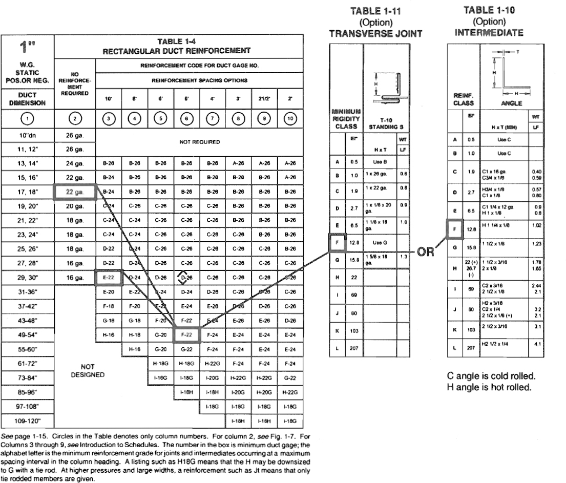
The number in the cell is minimum duct gage; the letter code is type of joint or intermediate reinforcement, whichever you choose. This applies for joint-to-joint, joint-to-intermediate, or intermediate-to-intermediate intervals. If, for example, you are using 5’ (1.5 m) joint spacing and do not want to use between-joint reinforcements stay in the 5’ (1.5 m) column (column 6) until it becomes “Not Designed”; then you go to column 9 to find the joint rating and the intermediate (between-joint) bracing and the potentially lighter gage duct wall permitted with 2-1/2’ (0.75 m) reinforcement spacing.
If the maximum short side reinforcement spacing thus found exceeds a joint spacing that you are committed to, go to the column with the joint spacing to find the joint size. Even though the duct gage listed at this width-spacing cell may be less, the joint rating cannot be less than at this cell.
In the table, an entry such as H-18G means that the H reinforcement size may be downsized to a G per section 1.10 if an internal tie rod is used. This does not apply for joints that require tie rods on both sides of the joint. In some schedules, only the tie rodded construction is given. Kt-18 is an example.
The HVAC-DCS Text makes provision for use of equivalent substitutions. Use Chapter 7 to evaluate these.
Very large ducts may require internal hangers as shown in Figure 4-6 or may require other internal supports to provide shape retention. Such internal supports should be illustrated on the contract drawings.
The rectangular duct construction standards provide the following options for constructing ducts: a) those unreinforced and joined by flat type connections only, b) those joined by flat type joint connectors backed by a qualified reinforcement, c) those joined by an upright connector that meets reinforcement requirements alone or in conjunction with an incorporated reinforcement, and d) in sizes over 48” (1.2 m) width, those using tie rods that permit the use of smaller reinforcements. Not all options exist at all sizes and all static pressure classes. The options are provided to correlate performance with economy and the preference of fabricators and specifiers. SMACNA does not validate equivalency.
1.13Example: 54” × 18” duct, 5 ft joint spacing. On 54” sides use F joints on 22 ga. On 18” sides flat slips or drives qualify per column 2.
Example: 54” × 30” duct, 22 gage. Use F at 5 ft. on 54”. On 30” use D at 5 ft. or E at 10 ft. If you put joints on the 30” side at 5 ft. spacing, they must be D rated.
Comment: If the table requires a letter code, all joints on that side must qualify for the minimum code letter related to the minimum gage and the spacing.

Spacing refers to letter code: use joint-to-joint, joint-to-intermediate or intermediate-to-intermediate. Columns 3 to 10 are alternatives.
The drive slip is accepted as being A, B or C rated up to 20” length.
The tables can be investigated to suit a preference for each of several features:
Sometimes, if a project calls for small amounts of ductwork in many size ranges or pressure classes, it may be more economical to select heavier constructions than are required, so that fewer variations are needed.
The duct construction tables define relationships between static pressure, width, wall thickness, reinforcement spacing, and reinforcement strength so that ducts have adequate strength and acceptable deflection limits. The greater dimension of a duct determines the duct gage for all four sides. This applies to reinforced and unreinforced ducts.
The first step in determining construction requirements is to locate the table with the applicable static pressure.
Duct sides having a gage listed in the second column of Tables 1-3 to 1-9 do not require reinforcement. These are summarized in Table 1-24. Flat type joints may be used at any spacing. Flat slips and drives must not be less than two gages lower than the duct gage or below 24 gage (0.70 mm).
The T-1 drive slip connection provides sufficient rigidity to be treated as Class A, B or C reinforcement within the limits of Table 1-25. This gives the appearance of increasing the range of unreinforced duct sizes.
In the Reinforcement Spacing columns of Tables 1-3 through 1-9, across from each duct width, each cell shows that duct width’s minimum duct gage as a number and its minimum reinforcement grade as a letter. The arrow indicates that the right most value continues to the end of the row because the minimum duct gage and reinforcement grade remain the same for shorter spacings. Any cell within a row is an acceptable selection for that duct width. Reinforcement spacings of 10 feet (3.0 m) to 2 feet (0.61 m) are alternative choices. See appendices 13 to 17 for discussion of variables that affect choices.
First investigate the duct side with the greater dimension because this side dictates the duct gage. Then find the smaller duct dimension in the first column, and on the same horizontal line locate the duct gage of the wide side. If the duct gage is in the second column, no reinforcement is required on that side; otherwise, the minimum reinforcement code is the letter listed under the spacing used. The actual duct gage may occur in a column giving allowable spacing greater than will be used. In such a case the minimum reinforcement grade is that associated with the actual spacing.
The reinforcement spacing in Tables 1-3 to 1-9 denotes distance between two joints or two intermediate reinforcements or from a joint to an intermediate member. Any joint or reinforcement member having a corresponding letter code in Tables 1-12 through 1-16 may be used to comply.
The letter code for reinforcement corresponds to a stiffness index number (EI). This is the modulus of elasticity multiplied by a moment of inertia that is based on the contributing elements of the connector, the reinforcement, the duct wall, or combinations of these. Unless other evidence of adequate strength and rigidity is presented, equivalent construction must meet the EI index associated with the code letter.
In some cases (for example, pocket locks and standing seams), the metal in the duct counts in the joint qualification. A minimum gage of duct that is heavier than the duct gage shown in Tables 1-3 through 1-9 may be indicated by the joint specifications in Tables 1-12 and 1-13.
Flat slips or drives (or any flat joint shown) may be used at one of the spacing limits, provided that a backup member (of the intermediate type) is used with them; the joint is then rated by the backup member taken from Table 1-10.
Tie rod duct construction described on pages 1-27 through 1-30 is also an alternative. For certain ducts of dimension greater than 48” (1.2 m), alternative sizes of reinforcement using tie rods is depicted in the tables. An entry such as H-18G indicates that on 18 gage (1.3 mm) duct, the reinforcement code for
1.15either joint or intermediate stiffener is H class, but G class may be substituted if an available tie rod alternative is selected.
For ducts over 120” (4.72 m) width, only tie rod construction is indicated in order to limit the size of reinforcements. The table entry Ht-18, for example, designates 18 gage duct with H class joints and intermediates having tie rods or straps at intervals not exceeding 60 inches (1524 mm). See Figure 1-12. Very large ducts may require internal hangers as shown in Figure 4-8 or may require other internal supports to provide shape retention. Such internal supports should be illustrated on the contract drawings. Other construction that meets the functional criteria in Section VII may be provided.
Example l, 18” × 12” (457 × 305 mm) duct:
If the duct is of 22 gage (0.85 mm), the second column shows that it may be unreinforced.
If the duct is of 24 gage (0.70 mm), the 12” (305 mm) side may be unreinforced, but grade B joints are required at 10 feet (3 m) maximum spacing on the 18” (457 mm) sides. However, Table 1-18 allows the T-1 drive slip (alone) to be used on the 18” (457 mm) sides. Any joint used on the 18” side must meet grade B regardless of joint spacing.
If the duct is of 26 gage (0.55 mm), the 12” (305 mm) side may be unreinforced, but on the 18” (457 mm) sides, the maximum reinforcement spacing is 8 feet (2.4 m) and the minimum size is grade B. By Table 1-18, the T-1 drive slip is acceptable as grade A (up to 20” (508 mm) width and 8 feet (2.4 m) spacing). Substitution of C or D for B would still not permit a reinforcement spacing greater than 8 feet (2.4 m) because the minimum gage associated with 10 feet (3 m) spacing is 24 (0.70 mm).
Example 2, 30” × 18” (762 × 457 mm) duct:
The choices for the 30” (762 mm) side are: 16 ga (1.61 mm) for unreinforced; E on 22 ga (0.85 mm) at 10 feet (3 m); D on 24 ga (0.70 mm) at 8 feet (2.4 m), or D on 26 ga (0.55 mm) at 6 feet (1.8 m) max. or C at 4 feet (1.2 m) max. For the 18” (457 mm) side, the choices are the same as outlined in Example 1 for 18” (457 mm) width.
Example 3, 54” × 30” (1372 × 762 mm) duct, with 5 feet (1.5 m) joint spacing preselected:
For 54” (1372 mm) width, F code is required if 22 ga (0.85 mm) is selected. 24 ga (0.70) duct may be used with 5 feet (1.5 m) joint spacing but an E rated intermediate (between E rated joints) would be added (effectively changing the reinforcement spacing to 2-1/2 feet (0.76 m)).
For the 30” (762 mm) side: Grade D is required (for 5 feet (1.5 m) maximum spacing) on any duct gage less than 16 (1.61 mm).
If you did not have the 5 feet (1.5 m) joint limitation and it was economical to do so, 16 ga (1.61 mm) duct unreinforced on the 30” (762 mm) sides and G joints at 10 feet (3 m) spacing on 54” (1372 mm) sides is acceptable.
Example 4, 72” × 72” (100 × 188 mm), with 5’ (1.5 m) joint spacing and no intermediate reinforcing use 18 ga (1.31 mm) duct with H rated joints or G rated joints with tie rods added (Gt) or use 24 ga (0.70 mm) with 21/2 feet (0.75 m) spacing and F ratings.
This introduction does not review all aspects of construction. It is an overview. Certain other limitations will appear later in the text and tables. For example, certain joints have been assigned maximum pressure classes. However, other limits may be acceptable if they can be shown to result in equivalent construction. See the appendix for other useful tables and commentary.
Consult NFPA Standard 90B and other codes and specifications applicable for use of materials thinner than 26 gage (0.55 mm) in residential work.
Unless otherwise specified or allowed, rectangular ductwork shall be constructed in accordance with Tables 1-3 through l-13 and with details associated with them.
The duct gage tables are based on G-60 coated galvanized steel of lock forming grade conforming to ASTM Standards A653 and A924. Uncoated steel, prepainted steel, steel with metal coating such as aluminum or aluminum-zinc compounds, and stainless steel may be used if a minimum corresponding base metal thickness and material strength is provided. Lock forming grades of such material must be used.
1.16The use of alternative materials requires specification or approval by a designer. The surface conditions, hardness, ductility, corrosion resistance, and other characteristics of these materials must be judged acceptable by the designer for the planned service.
Specifications that refer to use of material that is two gages heavier mean two numbers separated in a series that uses both odd and even number progression; e.g., 18 is two gages heavier than 20 on Appendix pages A.2 and A.3.
Unless otherwise specified, reinforcement may be uncoated steel or galvanized steel.
A reinforcement code classification (letter and EI index) higher than indicated must be substituted when the tables do not provide the specific construction details for a lower classification. A higher rated construction member may also be substituted for convenience.
Joint spacing on unreinforced ducts is unlimited. On ducts that require reinforcement, joint spacing is unrestricted except that the joint itself must qualify for the minimum reinforcement code associated with the reinforcement spacing.
Duct sides that are 19” (483 mm) and over and are 20 gage (1.00 mm) or less, with more than 10 square feet (0.93 square m) of unbraced panel area, shall be crossbroken or beaded as indicated in Figure 1-8 unless they are lined or externally insulated. Ducts that are of heavier gage, smaller dimensions, and smaller panel area and those that are lined or externally insulated are not required to have crossbreaking or beading.
Fittings shall be reinforced like sections of straight duct. On size change fittings, the greater fitting dimension determines the duct gage. Where fitting curvature or internal member attachments provide equivalent rigidity, such features may be credited as reinforcement.
Duct wall thickness, joints, seams, and reinforcements must be coordinated to provide proper assembly.
Other construction that meets the functional criteria in Section VII or is as serviceable as that produced by the construction tables may be provided.
1.17| 1/2” W.G. STATIC POS.OR NEG. |
|||||||||
|---|---|---|---|---|---|---|---|---|---|
| NO REINFORCEMENT REQUIRED | REINFORCEMENT CODE FOR DUCT GAGE NO. | ||||||||
| REINFORCEMENT SPACING OPTIONS | |||||||||
| DUCT DIMENSION |
10’ | 8’ | 6’ | 5’ | 4’ | 3’ | 21/2’ | 2’ | |
 |
 |
 |
 |
 |
 |
 |
 |
 |
 |
| 10”dn. | 26 ga. | NOT REQUIRED | |||||||
| 11, 12” | 26 ga. | ||||||||
| 13, 14” | 26 ga. | ||||||||
| 15, 16” | 26 ga. | ||||||||
| 17, 18” | 26 ga. | ||||||||
| 19, 20” | 24 ga. | B-26 | B-26 | B-26 | B-26 | B-26 | B-26 | A-26 | A-26 |
| 21, 22” | 22 ga. | B-26 | B-26 | B-26 | B-26 | B-26 | B-26 | B-26 | A-26 |
| 23, 24” | 22 ga. | C-26 | C-26 | C-26 | B-26 | B-26 | B-26 | B-26 | B-26 |
| 25, 26” | 20 ga. | C-26 | C-26 | C-26 | C-26 | B-26 | B-26 | B-26 | B-26 |
| 27, 28” | 18 ga. | C-24 | C-26 | C-26 | C-26 | C-26 | B-26 | B-26 | B-26 |
| 29, 30” | 18 ga. | C-24 | C-26 | C-26 | C-26 | C-26 | B-26 | B-26 | B-26 |
| 31-36” | 16 ga. | D-22 | D-24 | C-26 | C-26 | C-26 | C-26 | C-26 | B-26 |
| 37-42” | E-20 | E-24 | D-24 | D-26 | C-26 | C-26 | C-26 | C-26 | |
| 43-48” | E-20 | E-22 | E-24 | E-26 | D-26 | D-26 | C-26 | C-26 | |
| 49-54” | F-18 | F-20 | E-22 | E-26 | E-26 | E-26 | D-26 | C-26 | |
| 55-60” | G-18 | F-20 | F-22 | E-24 | E-24 | E-26 | E-26 | D-26 | |
| 61-72” | H-16 | H-18 | F-20 | F-22 | F-24 | E-24 | E-24 | E-24 | |
| 73-84” | 1-16G | H-18G | H-22G | G-24 | F-24 | F-24 | F-24 | ||
| 85-96” | NOT DESIGNED | 1-16G | 1-18G | H-20G | H-22G | G-22 | F-22 | F-22 | |
| 97-108” | 1-18G | 1-18G | H-18G | H-18G | G-18 | ||||
| 109-120” | 1-18G | H-18G | H-18G | ||||||
See page 1-15. Circles in the Table denotes only column numbers. For column 2, see Fig. 1-7. For columns 3 through 9, see Introduction to Schedules. The number in the box is minimum duct gage; the alphabet letter is the minimum reinforcement grade for joints and intermediates occurring at a maximum spacing interval in the column heading. A letter to the right of the gage gives a tie rodded reinforcement alternative. A “t” compels use of tie rod(s) for the reinforcement listing. For beading or crossbreaking, see Fig. 1-8.
1.18| 125 Pa W.G. STATIC POS.OR NEG. |
|||||||||
|---|---|---|---|---|---|---|---|---|---|
| NO REINFORCEMENT REQUIRED | REINFORCEMENT CODE AND DUCT THICKNESS (mm) | ||||||||
| REINFORCEMENT SPACING OPTIONS (m) | |||||||||
| DUCT DIMENSION | 3.0 | 2.4 | 1.8 | 1.5 | 1.2 | 0.90 | 0.75 | 0.60 | |
 |
 |
|
|
|
|
|
|
|
|
| 250 dn. | 0.55 | NOT REQUIRED | |||||||
| 251, 300 | 0.55 | ||||||||
| 301, 350 | 0.55 | ||||||||
| 351, 400 | 0.55 | ||||||||
| 401, 450 | 0.55 | ||||||||
| 451, 500 | 0.70 | B-0.55 | B-0.55 | B-0.55 | B-0.55 | B-0.55 | B-0.55 | A-0.55 | A-0.55 |
| 501, 550 | 0.85 | B-0.55 | B-0.55 | B-0.55 | B-0.55 | B-0.55 | B-0.55 | B-0.55 | A-0.55 |
| 551, 600 | 0.85 | C-0.55 | C-0.55 | C-0.55 | B-0.55 | B-0.55 | B-0.55 | B-0.55 | B-0.55 |
| 601, 650 | 1.00 | C-0.55 | C-0.55 | C-0.55 | C-0.55 | B-0.55 | B-0.55 | B-0.55 | B-0.55 |
| 651, 700 | 1.31 | C-0.70 | C-0.55 | C-0.55 | C-0.55 | C-0.55 | B-0.55 | B-0.55 | B-0.55 |
| 701, 750 | 1.31 | C-0.70 | C-0.55 | C-0.55 | C-0.55 | C-0.55 | B-0.55 | B-0.55 | B-0.55 |
| 751, 900 | 1.61 | D-0.85 | D-0.70 | C-0.55 | C-0.55 | C-0.55 | C-0.55 | C-0.55 | B-0.55 |
| 901, 1000 | E-1.00 | E-0.70 | D-0.70 | D-0.55 | C-0.55 | C-0.55 | C-0.55 | C-0.55 | |
| 1001, 1200 | E-1.00 | E-0.85 | E-0.70 | E-0.55 | D-0.55 | D-0.55 | C-0.55 | C-0.55 | |
| 1201, 1300 | F-1.31 | F-1.00 | E-0.85 | E-0.55 | E-0.55 | E-0.55 | D-0.55 | C-0.55 | |
| 1301, 1500 | G-1.31 | F-1.00 | F-0.85 | E-0.70 | E-0.70 | E-0.55 | E-0.55 | D-0.55 | |
| 1501, 1800 | H-1.61 | H-1.31 | F-1.00 | F-0.85 | F-0.70 | E-0.70 | E-0.70 | E-0.70 | |
| 1801, 2100 | I-1.61G | H-1.31G | H-0.85G | G-0.70 | F-0.70 | F-0.70 | F-0.70 | ||
| 2101, 2400 | NOT DESIGNED | I-1.61G | I-1.31G | H-1.00G | H-0.85G | G-0.85 | F-0.85 | F-0.85 | |
| 2401, 2700 | I-1.31G | I-1.31G | H-1.31G | H-1.31G | G-1.31 | ||||
| 2701, 3000 | H-1.31G | H-1.31G | H-1.31G | ||||||
See page 1-15. Circles in the Table denotes only column numbers. For column 2, see Fig. 1-7. For columns 3 through 9, see Introduction to Schedules. The number in the box is minimum duct gage; the alphabet letter is the minimum reinforcement grade for joints and intermediates occurring at a maximum spacing interval in the column heading. A letter to the right of the gage gives a tie rodded reinforcement alternative. A “t” compels use of tie rod(s) for the reinforcement listing. For beading or crossbreaking, see Fig. 1-8.
1.19| 1” W.G. STATIC POS.OR NEG. |
|||||||||
|---|---|---|---|---|---|---|---|---|---|
| NO REINFORCEMENT REQUIRED | REINFORCEMENT CODE FOR DUCT GAGE NO. | ||||||||
| REINFORCEMENT SPACING OPTIONS | |||||||||
| DUCT DIMENSION | 10’ | 8’ | 6’ | 5’ | 4’ | 3’ | 21/2’ | 2’ | |
|
|
|
|
|
|
|
|
|
|
| 10”dn. | 26 ga. | NOT REQUIRED | |||||||
| 11, 12” | 26 ga. | ||||||||
| 13, 14” | 24 ga. | B-26 | B-26 | B-26 | B-26 | B-26 | A-26 | A-26 | A-26 |
| 15, 16” | 22 ga. | B-24 | B-26 | B-26 | B-26 | B-26 | B-26 | B-26 | A-26 |
| 17, 18” | 22 ga. | B-24 | B-26 | B-26 | B-26 | B-26 | B-26 | B-26 | B-26 |
| 19, 20” | 20 ga. | C-24 | C-26 | C-26 | C-26 | C-26 | B-26 | B-26 | B-26 |
| 21, 22” | 18 ga. | C-24 | C-24 | C-26 | C-26 | C-26 | B-26 | B-26 | B-26 |
| 23, 24” | 18 ga. | C-24 | C-24 | C-26 | C-26 | C-26 | C-26 | B-26 | B-26 |
| 25, 26” | 18 ga. | D-22 | D-24 | C-26 | C-26 | C-26 | C-26 | C-26 | B-26 |
| 27, 28” | 16 ga. | D-22 | D-24 | D-26 | C-26 | C-26 | C-26 | C-26 | C-26 |
| 29, 30” | 16 ga. | E-22 | D-24 | D-26 | D-26 | C-26 | C-26 | C-26 | C-26 |
| 31-36” | E-20 | E-22 | E-24 | D-24 | D-26 | C-26 | C-26 | C-26 | |
| 37-42” | F-18 | F-20 | E-22 | E-24 | E-26 | D-26 | D-26 | C-26 | |
| 43-48” | G-16 | G-18 | F-20 | F-22 | E-24 | E-26 | E-26 | D-26 | |
| 49-54” | H-16 | H-18 | G-20 | F-22 | F-24 | E-24 | E-24 | E-24 | |
| 55-60” | H-18 | G-20 | G-22 | F-24 | F-24 | E-24 | E-24 | ||
| 61-72” | NOT DESIGNED | H-18G | H-18G | H-22G | F-24 | F-24 | F-24 | ||
| 73-84” | I-16G | I-18G | I-20G | H-22G | H-22G | G-22 | |||
| 85-96” | I-16H | I-18H | I-20G | H-20G | H-22G | ||||
| 97-108” | I-18G | I-18G | I-18G | I-18G | |||||
| 109-120” | I-18H | I-18H | I-18G | ||||||
See page 1-15. Circles in the Table denotes only column numbers. For column 2, see Fig. 1-7. For columns 3 through 9, see Introduction to Schedules. The number in the box is minimum duct gage; the alphabet letter is the minimum reinforcement grade for joints and intermediates occurring at a maximum spacing interval in the column heading. A letter to the right of the gage gives a tie rodded reinforcement alternative. A “t” compels use of tie rod(s) for the reinforcement listing. For beading or crossbreaking, see Fig. 1-8.
1.20| 250 Pa W.G. STATIC POS.OR NEG. |
|||||||||
|---|---|---|---|---|---|---|---|---|---|
| NO REINFORCEMENT REQUIRED | REINFORCEMENT CODE AND DUCT THICKNESS (mm) | ||||||||
| REINFORCEMENT SPACING OPTIONS (m) | |||||||||
| DUCT DIMENSION | 3.0 | 2.4 | 1.8 | 1.5 | 1.2 | 0.90 | 0.75 | 0.60 | |
|
|
|
|
|
|
|
|
|
|
| 250 dn. | 0.55 | NOT REQUIRED | |||||||
| 251, 300 | 0.55 | ||||||||
| 301, 350 | 0.7 | B-0.55 | B-0.55 | B-0.55 | B-0.55 | B-0.55 | A-0.55 | A-0.55 | A-0.55 |
| 351, 400 | 0.85 | B-0.70 | B-0.55 | B-0.55 | B-0.55 | B-0.55 | B-0.55 | B-0.55 | A-0.55 |
| 401, 450 | 0.85 | B-0.70 | B-0.55 | B-0.55 | B-0.55 | B-0.55 | B-0.55 | B-0.55 | B-0.55 |
| 451, 500 | 1 | C-0.70 | C-0.55 | C-0.55 | C-0.55 | C-0.55 | B-0.55 | B-0.55 | B-0.55 |
| 501, 550 | 1.31 | C-0.70 | C-0.70 | C-0.55 | C-0.55 | C-0.55 | B-0.55 | B-0.55 | B-0.55 |
| 551, 600 | 1.31 | C-0.70 | C-0.70 | C-0.55 | C-0.55 | C-0.55 | C-0.55 | B-0.55 | B-0.55 |
| 601, 650 | 1.31 | D-0.85 | D-0.70 | C-0.55 | C-0.55 | C-0.55 | C-0.55 | C-0.55 | B-0.55 |
| 651, 700 | 1.61 | D-0.85 | D-0.70 | D-0.55 | C-0.55 | C-0.55 | C-0.55 | C-0.55 | C-0.55 |
| 701, 750 | 1.61 | E-0.85 | D-0.70 | D-0.55 | D-0.55 | C-0.55 | C-0.55 | C-0.55 | C-0.55 |
| 751, 900 | E-1.00 | E-0.85 | E-0.70 | D-0.70 | D-0.55 | C-0.55 | C-0.55 | C-0.55 | |
| 901, 1000 | F-1.31 | F-1.00 | E-0.85 | E-0.70 | E-0.55 | D-0.55 | D-0.55 | C-0.55 | |
| 1001, 1200 | G-1.61 | G-1.31 | F-1.00 | F-0.85 | E-0.70 | E-0.55 | E-0.55 | D-0.55 | |
| 1201, 1300 | H-1.61 | H-1.31 | G-1.00 | F-0.85 | F-0.70 | E-0.70 | E-0.70 | E-0.70 | |
| 1301, 1500 | H-1.31 | G-1.00 | G-0.85 | F-0.70 | F-0.70 | E-0.70 | E-0.70 | ||
| 1501, 1800 | H-1.31G | H-1.31G | H-0.85G | F-0.70 | F-0.70 | F-0.70 | |||
| 1801, 2100 | NOT DESIGNED | I-1.61G | I-1.31G | I-1.00G | H-0.85G | H-0.85G | G-0.85 | ||
| 2101, 2400 | I-1.61H | I-1.31H | I-1.00G | H-1.00G | H-0.85G | ||||
| 2401, 2700 | I-1.31H | I-1.31G | I-1.31G | I-1.31G | |||||
| 2701, 3000 | I-1.31H | I-1.31H | I-1.31G | ||||||
See page 1-15. Circles in the Table denotes only column numbers. For column 2, see Fig. 1-7. For columns 3 through 9, see Introduction to Schedules. The number in the box is minimum duct gage; the alphabet letter is the minimum reinforcement grade for joints and intermediates occurring at a maximum spacing interval in the column heading. A letter to the right of the gage gives a tie rodded reinforcement alternative. A “t” compels use of tie rod(s) for the reinforcement listing. For beading or crossbreaking, see Fig. 1-8.
1.21| 2” W.G. STATIC POS.OR NEG. |
|||||||||
|---|---|---|---|---|---|---|---|---|---|
| NO REINFORCEMENT REQUIRED | REINFORCEMENT CODE FOR DUCT GAGE NO. | ||||||||
| REINFORCEMENT SPACING OPTIONS | |||||||||
| DUCT DIMENSION | 10’ | 8’ | 6’ | 5’ | 4’ | 3’ | 21/2’ | 2’ | |
|
|
|
|
|
|
|
|
|
|
| 10”dn. | 26 ga. | NOT REQUIRED | |||||||
| 11, 12” | 24 ga. | B-26 | B-26 | B-26 | B-26 | B-26 | B-26 | B-26 | |
| 13, 14” | 22 ga. | B-24 | B-26 | B-26 | B-26 | B-26 | B-26 | B-26 | |
| 15, 16” | 20 ga. | C-22 | C-24 | C-24 | C-26 | C-26 | C-26 | B-26 | B-26 |
| 17, 18” | 20 ga. | C-22 | C-24 | C-24 | C-26 | C-26 | C-26 | C-26 | B-26 |
| 19, 20” | 18 ga. | C-20 | C-22 | C-24 | C-26 | C-26 | C-26 | C-26 | C-26 |
| 21, 22” | 16 ga. | D-20 | D-22 | D-24 | D-26 | C-26 | C-26 | C-26 | C-26 |
| 23, 24” | 16 ga. | E-20 | E-22 | D-24 | D-26 | D-26 | C-26 | C-26 | C-26 |
| 25, 26” | E-20 | E-22 | E-24 | D-26 | D-26 | C-26 | C-26 | C-26 | |
| 27, 28” | F-18 | E-20 | E-22 | E-24 | D-26 | D-26 | C-26 | C-26 | |
| 29, 30” | F-18 | F-20 | E-22 | E-24 | E-26 | D-26 | D-26 | C-26 | |
| 31-36” | G-16 | G-18 | F-20 | F-22 | E-24 | E-26 | D-26 | D-26 | |
| 37-42” | H-16 | G-18 | G-20 | F-24 | E-24 | E-26 | E-26 | ||
| 43-48” | I-16 | H-18 | H-20 | G-22 | F-24 | F-24 | E-24 | ||
| 49-54” | I-16G | H-18G | H-20G | G-24 | F-24 | F-24 | |||
| 55-60” | I-16G | I-18G | H-18G | G-22 | G-24 | F-24 | |||
| 61-72” | NOT DESIGNED | J-16H | I-18G | H-22G | H-22G | H-24 | |||
| 73-84” | I-18G | I-20G | I-22G | I-22G | |||||
| 85-96” | J-18H | I-18H | I-20H | I-22H | |||||
| 97-108” | K-18H | J-18H | I-18H | ||||||
| 109-120” | K-18I | J-18I | |||||||
See page 1-15. Circles in the Table denotes only column numbers. For column 2, see Fig. 1-7. For columns 3 through 9, see Introduction to Schedules. The number in the box is minimum duct gage; the alphabet letter is the minimum reinforcement grade for joints and intermediates occurring at a maximum spacing interval in the column heading. A letter to the right of the gage gives a tie rodded reinforcement alternative. A “t” compels use of tie rod(s) for the reinforcement listing. For beading or crossbreaking, see Fig. 1-8.
1.22| 500 Pa STATIC POS.OR NEG. |
|||||||||
|---|---|---|---|---|---|---|---|---|---|
| NO REINFORCEMENT REQUIRED | REINFORCEMENT CODE FOR DUCT THICKNESS (mm) | ||||||||
| REINFORCEMENT SPACING OPTIONS (m) | |||||||||
| DUCT DIMENSION | 3.0 | 2.4 | 1.8 | 1.5 | 1.2 | 0.90 | 0.75 | 0.60 | |
|
|
|
|
|
|
|
|
|
|
| 250 dn. | 0.55 | NOT REQUIRED | |||||||
| 251, 300 | 0.70 | B-0.55 | B-0.55 | B-0.55 | B-0.55 | B-0.55 | B-0.55 | B-0.55 | |
| 301, 350 | 0.85 | B-0.70 | B-0.55 | B-0.55 | B-0.55 | B-0.55 | B-0.55 | B-0.55 | |
| 351, 400 | 1.00 | C-0.85 | C-0.70 | C-0.70 | C-0.55 | C-0.55 | C-0.70 | B-0.55 | B-0.70 |
| 401, 450 | 1.00 | C-0.85 | C-0.70 | C-0.70 | C-0.55 | C-0.55 | C-0.55 | C-0.55 | B-0.70 |
| 451, 500 | 1.31 | C-1.00 | C-0.85 | C-0.70 | C-0.55 | C-0.55 | C-0.55 | C-0.55 | C-0.55 |
| 501, 550 | 1.61 | D-1.00 | D-0.85 | D-0.70 | D-0.55 | C-0.55 | C-0.55 | C-0.55 | C-0.55 |
| 551, 600 | 1.61 | E-1.00 | E-0.85 | D-0.70 | D-0.55 | D-0.55 | C-0.55 | C-0.55 | C-0.55 |
| 601, 650 | E-1.00 | E-0.85 | E-0.70 | D-0.55 | D-0.55 | C-0.55 | C-0.55 | C-0.55 | |
| 651, 700 | F-1.31 | E-1.00 | E-0.85 | E-0.70 | D-0.55 | D-0.55 | C-0.55 | C-0.55 | |
| 701, 750 | F-1.31 | F-1.00 | E-0.85 | E-0.70 | E-0.55 | D-0.55 | D-0.55 | C-0.55 | |
| 701, 900 | G-1.61 | G-1.31 | F-1.00 | F-0.85 | E-0.70 | E-0.55 | D-0.55 | D-0.55 | |
| 901, 1000 | H-1.61 | G-1.31 | G-1.00 | F-0.70 | E-0.70 | E-0.55 | E-0.55 | ||
| 1001, 1200 | I-1.61 | H-1.31 | H-1.00 | G-0.85 | F-0.70 | F-0.70 | E-0.70 | ||
| 1201, 1300 | I-1.61G | H-1.31G | H-1.00G | G-0.70 | F-0.70 | F-0.70 | |||
| 1301, 1500 | I-1.61G | H-1.31G | H-1.31G | G-0.85 | G-0.70 | F-0.70 | |||
| 1501, 1800 | NOT DESIGNED | I-1.61H | I-1.31G | H-0.85G | H-0.85G | H-0.70 | |||
| 1801, 2100 | J-1.31G | I-1.00G | I-0.85G | I-0.85G | |||||
| 2101, 2400 | J-1.31I | I-1.31H | I-1.00H | I-0.85H | |||||
| 2401, 2700 | K-1.31H | J-1.31H | I-1.31H | ||||||
| 2701, 3000 | K-1.31I | J-1.31I | |||||||
See page 1-15. Circles in the Table denotes only column numbers. For column 2, see Fig. 1-7. For columns 3 through 9, see Introduction to Schedules. The number in the box is minimum duct gage; the alphabet letter is the minimum reinforcement grade for joints and intermediates occurring at a maximum spacing in the column heading. A letter to the right of the gage gives a tie rodded reinforcement alternative. A “t” compels use of tie rod(s) for the reinforcement listing. For beading or crossbreaking, see Fig. 1-8.
1.23| 3” W.G. STATIC POS.OR NEG. |
|||||||||
|---|---|---|---|---|---|---|---|---|---|
| NO REINFORCEMENT REQUIRED | REINFORCEMENT CODE FOR DUCT GAGE NO. | ||||||||
| REINFORCEMENT SPACING OPTIONS | |||||||||
| DUCT DIMENSION | 10’ | 8’ | 6’ | 5’ | 4’ | 3’ | 21/2’ | 2’ | |
|
|
|
|
|
|
|
|
|
|
| 10”dn. | 24 ga. | NOT REQUIRED | B-26 | B-26 | B-26 | B-26 | B-26 | B-26 | |
| 11, 12” | 22 ga. | B-24 | B-24 | B-26 | B-26 | B-26 | B-26 | B-26 | |
| 13, 14” | 20 ga. | C-22 | C-24 | C-24 | C-26 | C-26 | B-26 | B-26 | |
| 15, 16” | 18 ga. | C-22 | C-24 | C-24 | C-26 | C-26 | C-26 | C-26 | |
| 17, 18” | 18 ga. | D-22 | D-24 | C-24 | C-26 | C-26 | C-26 | C-26 | |
| 19, 20” | 16 ga. | D-18 | D-20 | D-22 | D-24 | D-24 | C-26 | C-26 | C-26 |
| 21, 22” | 16 ga. | E-18 | E-20 | E-22 | D-24 | D-24 | D-26 | C-26 | C-26 |
| 23, 24” | 16 ga. | E-18 | E-18 | E-22 | E-24 | E-24 | D-26 | D-26 | C-26 |
| 25, 26” | F-18 | F-18 | E-22 | E-24 | E-24 | D-26 | D-26 | C-26 | |
| 27, 28” | F-16 | F-18 | F-20 | F-22 | E-24 | E-26 | D-26 | D-26 | |
| 29, 30” | G-16 | G-18 | F-20 | F-22 | E-24 | E-26 | E-26 | D-26 | |
| 31-36” | H-16G | H-18G | G-20 | F-22 | F-24 | E-26 | E-26 | ||
| 37-42” | H-18G | H-20G | G-22 | F-24 | F-24 | E-26 | |||
| 43-48” | I-16G | I-18G | H-20 | G-22 | G-24 | F-24 | |||
| 49-54” | NOT DESIGNED | I-18G | I-18G | H-22G | G-24 | G-24 | |||
| 55-60” | I-16G | I-18G | H-20G | H-22G | G-24 | ||||
| 61-72” | J-16H | I-20G | I-22G | I-24G | |||||
| 73-84” | J-18H | I-20H | I-22G | ||||||
| 85-96” | K-18I | J-18I | I-20H | ||||||
| 97-108” | L-18I | K-18I | |||||||
| 109-120” | L-18I | L-18I | |||||||
See page 1-15. Circles in the Table denotes only column numbers. For column 2, see Fig. 1-7. For columns 3 through 9, see Introduction to Schedules. The number in the box is minimum duct gage; the alphabet letter is the minimum reinforcement grade for joints and intermediates occurring at a maximum spacing interval in the column heading. A letter to the right of the gage gives a tie rodded reinforcement alternative. A “t” compels use of tie rod(s) for the reinforcement listing. For beading or crossbreaking, see Fig. 1-8.
1.24| 750 Pa STATIC POS.OR NEG. |
|||||||||
|---|---|---|---|---|---|---|---|---|---|
| NO REINFORCEMENT REQUIRED | REINFORCEMENT CODE FOR DUCT THICKNESS (mm) | ||||||||
| REINFORCEMENT SPACING OPTIONS (m) | |||||||||
| DUCT DIMENSION | 3.0 | 2.4 | 1.8 | 1.5 | 1.2 | 0.90 | 0.75 | 0.60 | |
|
|
|
|
|
|
|
|
|
|
| 250 dn. | 0.70 | B-0.55 | B-0.55 | B-0.55 | B-0.55 | B-0.55 | B-0.55 | ||
| 251, 300 | 0.85 | NOT REQUIRED | B-0.70 | B-0.70 | B-0.55 | B-0.55 | B-0.55 | B-0.55 | B-0.55 |
| 301, 350 | 1.00 | C-0.85 | C-0.70 | C-0.70 | C-0.55 | C-0.55 | B-0.55 | B-0.55 | |
| 351, 400 | 1.31 | C-0.85 | C-0.70 | C-0.70 | C-0.55 | C-0.55 | C-0.55 | C-0.55 | |
| 401, 450 | 1.31 | D-0.85 | D-0.70 | C-0.70 | C-0.55 | C-0.55 | C-0.55 | C-0.55 | |
| 451, 500 | 1.61 | D-1.31 | D-1.00 | D-0.85 | D-0.70 | D-0.70 | C-0.55 | C-0.55 | C-0.55 |
| 501, 550 | 1.61 | E-1.31 | E-1.00 | E-0.85 | D-0.70 | D-0.70 | D-0.55 | C-0.55 | C-0.55 |
| 551, 600 | 1.61 | E-1.31 | E-1.31 | E-0.85 | E-0.70 | E-0.70 | D-0.55 | D-0.55 | C-0.55 |
| 601, 650 | F-1.31 | F-1.31 | E-0.85 | E-0.70 | E-0.70 | D-0.55 | D-0.55 | C-0.55 | |
| 651, 700 | F-1.61 | F-1.31 | F-1.00 | F-0.85 | E-0.70 | E-0.55 | D-0.55 | D-0.55 | |
| 701, 750 | G-1.61 | G-1.31 | F-1.00 | F-0.85 | E-0.70 | E-0.55 | E-0.55 | D-0.55 | |
| 751, 900 | H-1.61 | H-1.31G | G-1.00 | F-0.85 | F-0.70 | E-0.55 | E-0.55 | ||
| 901, 1000 | H-1.31G | H-1.00G | G-0.85 | F-0.70 | F-0.70 | E-0.55 | |||
| 1001, 1200 | I-1.61G | I-1.31G | H-1.00G | G-0.85 | G-0.70 | F-0.70 | |||
| 1201, 1300 | I-1.31G | I-1.31G | H-0.85G | G-0.70 | G-0.70 | ||||
| 1301, 1500 | I-1.61H | I-1.31G | H-1.00G | H-0.85G | G-0.70 | ||||
| 1501, 1800 | J-1.61H | I-1.00G | I-0.85G | I-0.70G | |||||
| 1801, 2100 | NOT DESIGNED | J-1.31H | I-1.00H | I-0.85G | |||||
| 2101, 2400 | K-1.31I | J-1.31I | I-1.00H | ||||||
| 2401, 2700 | L-1.31I | K-1.31H | |||||||
| 2701, 3000 | L-1.31I | L-1.31I | |||||||
See page 1-15. Circles in the Table denotes only column numbers. For column 2, see Fig. 1-7. For columns 3 through 9, see Introduction to Schedules. The number in the box is minimum duct gage; the alphabet letter is the minimum reinforcement grade for joints and intermediates occurring at a maximum spacing interval in the column heading. A letter to the right of the gage gives a tie rodded reinforcement alternative. A “t” compels use of tie rod(s) for the reinforcement listing. For beading or crossbreaking. see Fig. 1-8.
1.25| 4” W.G. STATIC POS.OR NEG. |
|||||||||
|---|---|---|---|---|---|---|---|---|---|
| NO REINFORCEMENT REQUIRED | REINFORCEMENT CODE FOR DUCT GAGE NO. | ||||||||
| REINFORCEMENT SPACING OPTIONS | |||||||||
| DUCT DIMENSION | 10’ | 8’ | 6’ | 5’ | 4’ | 3’ | 21/2’ | 2’ | |
|
|
|
|
|
|
|
|
|
|
| 8”dn. | 24 ga. | NOT REQUIRED | B-26 | B-26 | B-26 | B-26 | B-26 | B-26 | |
| 9, 10” | 22 ga. | B-24 | B-26 | B-26 | B-26 | B-26 | B-26 | ||
| 11, 12” | 20 ga. | B-22 | B-22 | C-24 | C-26 | C-26 | C-26 | B-26 | B-26 |
| 13, 14” | 18 ga. | C-20 | C-22 | C-22 | C-24 | C-26 | C-26 | C-26 | C-26 |
| 15, 16” | 18 ga. | C-18 | D-20 | D-22 | C-24 | C-26 | C-26 | C-26 | C-26 |
| 17, 18” | 16 ga. | D-18 | D-20 | D-22 | D-24 | D-26 | C-26 | C-26 | C-26 |
| 19, 20” | E-18 | E-20 | E-22 | E-24 | D-24 | D-26 | C-26 | C-26 | |
| 21, 22” | E-18 | E-18 | E-20 | E-24 | E-24 | D-26 | D-26 | C-26 | |
| 23, 24” | F-18 | F-18 | F-20 | E-22 | E-24 | E-26 | D-26 | D-26 | |
| 25, 26” | G-18 | G-18 | F-20 | F-22 | E-24 | E-26 | E-26 | D-26 | |
| 27, 28” | H-16G | G-18 | G-20 | F-22 | F-24 | E-26 | E-26 | D-26 | |
| 29, 30” | H-16G | H-18G | G-18 | G-22 | F-24 | E-26 | E-26 | E-26 | |
| 31-36” | H-18G | H-20 | G-22 | F-24 | F-26 | E-26 | |||
| 37-42” | I-16G | I-18G | H-20G | G-22 | G-24 | F-26 | |||
| 43-48” | NOT DESIGNED | I-18G | I-18G | H-22G | H-24G | G-24 | |||
| 49-54” | I-16H | I-18G | I-20G | H-22G | H-24G | ||||
| 55-60” | J-16I | I-16H | I-20G | I-22G | H-24G | ||||
| 61-72” | J-18H | I-20H | I-22G | ||||||
| 73-84” | K-16I | J-18I | I-20H | ||||||
| 85-96” | K-18I | J-20I | |||||||
| 97-108” | L-18I | L-18I | |||||||
| 109-120” | L-18J | L-18J | |||||||
See page 1-15. Circles in the Table denotes only column numbers. For column 2, see Fig. 1-7. For columns 3 through 9, see Introduction to Schedules. The number in the box is minimum duct gage; the alphabet letter is the minimum reinforcement grade for joints and intermediates occurring at a maximum spacing interval in the column heading. A letter to the right of the gage gives a tie rodded reinforcement alternative. A “t” compels use of tie rod(s) for the reinforcement listing. For beading or crossbreaking, see Fig. 1-8.
1.26| 1000 Pa W.G. STATIC POS.OR NEG. |
|||||||||
|---|---|---|---|---|---|---|---|---|---|
| NO REINFORCEMENT REQUIRED | REINFORCEMENT CODE FOR DUCT GAGE NO. (mm) | ||||||||
| REINFORCEMENT SPACING OPTIONS (m) | |||||||||
| DUCT DIMENSION | 3.00 | 2.40 | 1.80 | 1.50 | 1.20 | 0.90 | 0.75 | 0.60 | |
|
|
|
|
|
|
|
|
|
|
| 200 dn. | 0.70 | NOT REQUIRED | B-0.55 | B-0.55 | B-0.55 | B-0.55 | B-0.55 | B-0.55 | |
| 230, 250 | 0.85 | B-0.70 | B-0.55 | B-0.55 | B-0.55 | B-0.55 | B-0.55 | ||
| 251, 300 | 1.00 | B-0.85 | B-0.85 | C-0.70 | C-0.55 | C-0.55 | C-0.55 | B-0.55 | B-0.55 |
| 301, 350 | 1.31 | C-1.00 | C-0.85 | C-0.85 | C-0.70 | C-0.55 | C-0.55 | C-0.55 | C-0.55 |
| 351, 400 | 1.31 | C-1.31 | D-1.00 | D-0.85 | D-0.70 | D-0.55 | C-0.55 | C-0.55 | C-0.55 |
| 401, 450 | 1.61 | D-1.31 | D-1.00 | D-0.85 | D-0.70 | D-0.55 | C-0.55 | C-0.55 | C-0.55 |
| 451, 500 | E-1.31 | E-1.00 | E-0.85 | E-0.70 | D-0.70 | D-0.55 | C-0.55 | C-0.55 | |
| 501, 550 | E-1.31 | E-1.31 | E-1.00 | E-0.70 | E-0.70 | D-0.55 | D-0.55 | C-0.55 | |
| 551, 600 | F-1.13 | F-1.31 | F-1.00 | E-0.85 | E-0.70 | E-0.55 | D-0.55 | D-0.55 | |
| 601, 650 | G-1.31 | G-1.31 | F-1.00 | F-0.85 | E-0.70 | E-0.55 | E-0.55 | D-0.55 | |
| 651, 700 | H-1.61 | G-1.31 | F-1.00 | F-0.85 | F-0.70 | E-0.55 | E-0.55 | D-0.55 | |
| 701, 750 | H-1.61 | G-1.31 | G-1.31 | G-0.85 | F-0.70 | E-0.55 | E-0.55 | E-0.55 | |
| 751, 900 | H-1.31G | H-1.00 | G-0.85 | F-0.70 | F-0.55 | E-0.55 | |||
| 901, 1000 | I-1.61G | I-1.31G | H-1.00G | G-0.85 | G-0.70 | F-0.55 | |||
| 1001, 1200 | NOT DESIGNED | I-1.31G | I-1.31G | H-0.85G | H-0.70G | G-0.704 | |||
| 1201, 1300 | I-1.61H | I-1.31G | I-1.00G | H-0.85G | H-0.70G | ||||
| 1301, 1500 | J-1.61I | I-1.61H | I-1.00G | I-0.85G | H-0.70G | ||||
| 1501, 1800 | J-1.31H | I-1.00H | I-0.85G | ||||||
| 1801, 2100 | K-1.61I | J-1.31I | I-1.00H | ||||||
| 2101, 2400 | K-1.31I | J-1.00I | |||||||
| 2401, 2700 | L-1.31I | L-1.31I | |||||||
| 2701, 3000 | L-1.31J | L-1.31J | |||||||
See page 1-15. Circles in the Table denotes only column numbers. For column 2, see Fig. 1-7. For columns 3 through 9, see Introduction to Schedules. The number in the box is minimum duct gage; the alphabet letter is the minimum reinforcement grade for joints and intermediates occurring at a maximum spacing interval in the column heading. A letter to the right of the gage gives a tie rodded reinforcement alternative. A “t” compels use of tie rod(s) for the reinforcement listing. For beading or crossbreaking, see Fig. 1-8.
1.27| 6” W.G. STATIC POS.OR NEG. |
|||||||||
|---|---|---|---|---|---|---|---|---|---|
| NO REINFORCEMENT REQUIRED | REINFORCEMENT CODE FOR DUCT GAGE NO. | ||||||||
| REINFORCEMENT SPACING OPTIONS | |||||||||
| DUCT DIMENSION | 10’ | 8’ | 6’ | 5’ | 4’ | 3’ | 21/2’ | 2’ | |
|
|
|
|
|
|
|
|
|
|
| 8”dn. | 24 ga. | NOT REQUIRED | C-26 | C-26 | B-26 | B-26 | B-26 | ||
| 9, 10” | 20 ga. | B-22 | C-24 | C-24 | B-26 | B-26 | B-26 | ||
| 11, 12” | 18 ga. | C-20 | C-20 | C-22 | C-24 | C-24 | C-26 | C-26 | C-26 |
| 13, 14” | 18 ga. | C-20 | C-20 | D-20 | D-22 | C-24 | C-26 | C-26 | C-26 |
| 15, 16” | 16 ga. | D-18 | D-18 | D-20 | D-22 | D-24 | D-26 | C-26 | C-26 |
| 17, 18” | E-18 | E-18 | E-20 | E-22 | E-24 | D-26 | D-26 | C-26 | |
| 19, 20” | F-16 | F-18 | F-20 | E-22 | E-24 | D-24 | D-26 | D-26 | |
| 21, 22” | F-16 | F-18 | F-20 | F-22 | F-24 | E-24 | E-26 | D-26 | |
| 23, 24” | G-18 | G-20 | F-22 | F-22 | E-24 | E-26 | E-26 | ||
| 25, 26” | H-16G | G-18 | G-20 | F-22 | F-24 | E-24 | E-24 | ||
| 27, 28” | H-16G | H-18G | H-20G | G-22 | F-24 | F-24 | E-24 | ||
| 29, 30” | H-18G | H-18G | G-22 | F-24 | F-24 | E-24 | |||
| 31-36” | I-16H | I-18H | H-20G | H-22G | G-24 | F-24 | |||
| 37-42” | I-16H | I-18G | H-20G | H-22G | G-22 | ||||
| 43-48” | NOT DESIGNED | I-18H | I-18H | I-22G | H-22G | ||||
| 49-54” | J-16H | I-18H | I-20G | I-22G | |||||
| 55-60” | J-18H | I-20H | I-22G | ||||||
| 61-72” | K-16I | J-18I | J-20H | ||||||
| 73-84” | L-16J | K-18I | |||||||
| 85-96” | It-16 | L-18J | |||||||
| 97-108” | Jt-16 | L-18J | |||||||
| 109-120” | Kt-16 | Kt-18 | |||||||
See page 1-15. Circles in the Table denotes only column numbers. For column 2, see Fig. 1-7. For columns 3 through 9, see Introduction to Schedules. The number in the box is minimum duct gage; the alphabet letter is the minimum reinforcement grade for joints and intermediates occurring at a maximum spacing interval in the column heading. A letter to the right of the gage gives a tie rodded reinforcement alternative. A “t” compels use of tie rod(s) for the reinforcement listing. For beading or crossbreaking, see Fig. 1-8.
1.28| 1500 Pa W.G. STATIC POS.OR NEG. |
|||||||||
|---|---|---|---|---|---|---|---|---|---|
| NO REINFORCEMENT REQUIRED | REINFORCEMENT CODE FOR DUCT GAGE NO. (mm) | ||||||||
| REINFORCEMENT SPACING OPTIONS (m) | |||||||||
| DUCT DIMENSION | 3.0 | 2.4 | 1.8 | 1.5 | 1.2 | 0.90 | 0.75 | 0.60 | |
|
|
|
|
|
|
|
|
|
|
| 200 dn. | 24 ga. | NOT REQUIRED | C-0.55 | C-0.55 | B-0.55 | B-0.55 | B-0.55 | ||
| 230, 250 | 20 ga. | B-0.85 | C-0.70 | C-0.70 | B-0.55 | B-0.55 | B-0.55 | ||
| 251, 300 | 18 ga. | C-1.00 | C-1.00 | C-0.85 | C-0.70 | C-0.70 | C-0.55 | C-0.55 | C-0.55 |
| 301, 350 | 18 ga. | C-1.00 | C-1.00 | D-1.00 | D-0.85 | C-0.70 | C-0.55 | C-0.55 | C-0.55 |
| 351, 400 | 16 ga. | D-1.31 | D-1.31 | D-1.00 | D-0.85 | D-0.70 | D-0.55 | C-0.55 | C-0.55 |
| 401, 450 | E-1.31 | E-1.31 | E-1.00 | E-0.85 | E-0.70 | D-0.55 | D-0.55 | C-0.55 | |
| 451, 500 | F-1.61 | F-1.31 | F-1.00 | E-0.85 | E-0.70 | D-0.70 | D-0.55 | D-0.55 | |
| 501, 550 | F-1.61 | F-1.31 | F-1.00 | F-0.85 | F-0.70 | E-0.70 | E-0.55 | D-0.55 | |
| 551, 600 | G-1.31 | G-1.00 | F-0.85 | F-0.85 | E-0.70 | E-0.70 | E-0.70 | ||
| 601, 650 | H-1.61G | G-1.31 | G-1.00 | F-0.85 | F-0.70 | E-0.70 | E-0.55 | ||
| 651, 700 | H-1.61G | H-1.31G | H-1.00G | G-0.85 | F-0.70 | F-0.70 | E-0.70 | ||
| 701, 750 | H-1.31G | H-1.31G | G-0.85 | F-0.70 | F-0.70 | E-0.70 | |||
| 750, 900 | I-1.61H | I-1.31H | H-1.00G | H-0.85G | G-0.70 | F-0.70 | |||
| 901, 1000 | 1-1.61H | I-1.31G | H-1.00G | H-0.85G | G-0.85 | ||||
| 1001, 1200 | NOT DESIGNED | I-1.31H | I-1.31H | I-0.85G | H-0.85G | ||||
| 1201, 1300 | J-1.61H | I-1.31H | I-1.00G | I-0.85G | |||||
| 1301, 1500 | J-1.31H | I-1.00H | I-0.85G | ||||||
| 1501, 1800 | K-1.61I | J-1.31I | J-1.00H | ||||||
| 1801, 2100 | L-1.61J | K-1.31I | |||||||
| 2101, 2400 | It-1.61 | L-1.31J | |||||||
| 2401, 2700 | Jt-1.61 | L-1.31J | |||||||
| 2700, 3000 | Kt-1.61 | Kt-1.31 | |||||||
See page 1-15. Circles in the Table denotes only column numbers. For column 2, see Fig. 1-7. For columns 3 through 9, see Introduction to Schedules. The number in the box is minimum duct gage; the alphabet letter is the minimum reinforcement grade for joints and intermediates occurring at a maximum spacing interval in the column heading. A letter to the right of the gage gives a tie rodded reinforcement alternative. A “t” compels use of tie rod(s) for the reinforcement listing. For beading or crossbreaking, see Fig. 1-8.
1.29| 10” W.G. STATIC POS.OR NEG. |
|||||||||
|---|---|---|---|---|---|---|---|---|---|
| NO REINFORCEMENT REQUIRED | REINFORCEMENT CODE FOR DUCT GAGE NO. | ||||||||
| REINFORCEMENT SPACING OPTIONS | |||||||||
| DUCT DIMENSION | 10’ | 8’ | 6’ | 5’ | 4’ | 3’ | 21/2’ | 2’ | |
|
|
|
|
|
|
|
|
|
|
| 8”dn. | 22 ga. | NOT REQUIRED | C-24 | C-24 | C-26 | C-26 | C-26 | ||
| 9, 10” | 18 ga. | C-20 | C-22 | C-24 | C-26 | C-26 | C-26 | ||
| 11, 12” | 16 ga. | C-18 | D-20 | D-22 | D-24 | C-26 | C-26 | C-26 | |
| 13, 14” | D-18 | E-18 | E-20 | D-22 | D-24 | D-26 | C-26 | ||
| 15, 16” | E-16 | E-18 | E-20 | E-22 | E-24 | D-24 | D-26 | ||
| 17, 18” | F-16 | F-18 | F-20 | F-20 | E-24 | E-24 | D-26 | ||
| 19, 20” | G-16 | G-18 | G-18 | F-20 | F-22 | E-24 | E-24 | ||
| 21, 22” | H-18G | G-18 | G-20 | F-22 | F-24 | E-24 | |||
| 23, 24” | H-18G | H-18G | H-20G | G-22 | F-24 | F-24 | |||
| 25, 26” | I-16G | H-18G | H-20G | G-22 | F-24 | F-24 | |||
| 27, 28” | I-16G | I-18G | H-18G | H-22G | G-24 | F-24 | |||
| 29, 30” | I-16G | I-18G | H-22G | H-24G | G-24 | ||||
| 31-36” | J-16H | I-18H | I-20G | H-22G | H-24G | ||||
| 37-42” | J-16I | I-18G | I-20H | I-22G | |||||
| 43-48” | NOT DESIGNED | J-18I | I-18H | I-22H | |||||
| 49-54” | K-16I | J-18H | 1-20H | ||||||
| 55-60” | L-16I | K-18I | J-20I | ||||||
| 61-72” | L-16J | L-18I | |||||||
| 73-84” | Lt-16 | ||||||||
| 85-96” | Lt-16 | ||||||||
| 97-108” | Lt-16 | ||||||||
| 109-120” | Lt-16 | ||||||||
See page 1-15. Circles in the Table denotes only column numbers. For column 2, see Fig. 1-7. For columns 3 through 9, see Introduction to Schedules. The number in the box is minimum duct gage; the alphabet letter is the minimum reinforcement grade for joints and intermediates occurring at a maximum spacing interval in the column heading. A letter to the right of the gage gives a tie rodded reinforcement alternative. A “t” compels use of tie rod(s) for the reinforcement listing. For beading or crossbreaking, see Fig. 1-8.
1.30| 2500 PA W.G. STATIC POS.OR NEG. |
|||||||||
|---|---|---|---|---|---|---|---|---|---|
| NO REINFORCEMENT REQUIRED | REINFORCEMENT CODE FOR DUCT GAGE NO. (mm) | ||||||||
| REINFORCEMENT SPACING OPTIONS (m) | |||||||||
| DUCT DIMENSION | 3.0 | 2.4 | 1.8 | 1.5 | 1.2 | 0.90 | 0.75 | 0.60 | |
|
|
|
|
|
|
|
|
|
|
| 200 dn. | 22 ga. | NOT REQUIRED | C-0.70 | C-0.70 | C-0.55 | C-0.55 | C-0.55 | ||
| 230, 250 | 18 ga. | C-1.00 | C-0.85 | C-0.70 | C-0.55 | C-0.55 | C-0.55 | ||
| 251, 300 | 16 ga. | C-1.31 | D-1.00 | D-0.85 | D-0.70 | C-0.55 | C-0.55 | C-0.55 | |
| 301, 350 | D-1.31 | E-1.31 | E-1.00 | D-0.85 | D-0.70 | D-0.55 | C-0.55 | ||
| 351, 400 | E-1.61 | E-1.31 | E-1.00 | E-0.85 | E-0.70 | D-0.70 | D-0.55 | ||
| 401, 450 | F-1.61 | F-1.31 | F-1.00 | F-1.00 | E-0.70 | E-0.70 | D-0.55 | ||
| 451, 500 | G-1.61 | G-1.31 | G-1.31 | F-1.00 | F-0.85 | E-0.70 | E-0.70 | ||
| 501, 550 | H-1.31G | G-1.31 | G-1.00 | F-0.85 | F-0.70 | E-0.70 | |||
| 551, 600 | H-1.31G | H-1.31G | H-1.00G | G-0.85 | F-0.70 | F-0.70 | |||
| 601, 650 | I-1.61G | H-1.31G | H-1.00G | G-0.85 | F-0.70 | F-0.70 | |||
| 651, 700 | I-1.61G | I-1.31G | H-1.31G | H-0.85G | G-0.70 | F-0.70 | |||
| 701, 750 | I-1.61G | I-1.31G | H-0.85G | H-0.70G | G-0.70 | ||||
| 751, 900 | J-1.61H | I-1.31H | I-1.00G | H-0.85G | H-0.70G | ||||
| 901, 1000 | J-1.61I | I-1.31G | I-1.00H | I-0.85G | |||||
| 1001, 1200 | NOT DESIGNED | J-1.31I | I-1.31H | I-0.85H | |||||
| 1201, 1300 | K-1.61I | J-1.31H | I-1.00H | ||||||
| 1301, 1500 | L-1.61I | K-1.31I | J-1.00I | ||||||
| 1501, 1800 | L-1.61J | L-1.00I | |||||||
| 1801, 2100 | Lt-1.61 | ||||||||
| 2101, 2400 | Lt-1.61 | ||||||||
| 2401, 2700 | Lt-1.61 | ||||||||
| 2701, 3000 | Lt-1.61 | ||||||||
See page 1-15. Circles in the Table denotes only column numbers. For column 2, see Fig. 1-7. For columns 3 through 9, see Introduction to Schedules. The number in the box is minimum duct gage; the alphabet letter is the minimum reinforcement grade for joints and intermediates occurring at a maximum spacing interval in the column heading. A letter to the right of the gage gives a tie rodded reinforcement alternative. A “t” compels use of tie rod(s) for the reinforcement listing. For beading or crossbreaking, see Fig. 1-8.
1.31| REINF. CLASS |  ANGLE |
 CHANNEL OR ZEE |
 HAT SECTION |
||||
|---|---|---|---|---|---|---|---|
| EI* | H × T (MIN) | WT | H × B × T (MIN) | WT | H × B × D × T (MIN) | WT | |
| LF | LF | LF | |||||
| A | 0.43 | Use C | Use B | Use F | |||
| B | 1.0 | Use C | 3/4 × 1/2 × 20 ga. | 0.24 | Use F | ||
| C | 1.9 | C1 × 16 ga. C3/4 × 1/8 |
0.40 0.57 |
3/4 × 1/2 × 18 ga. 1 × 3/4 × 20 ga. |
0.31 | Use F | |
| D | 2.7 | H3/4 × 1/8 C1 × 1/8 |
0.57 0.80 |
1 × 3/4 × 18 ga. | 0.45 | Use F | |
| E | 6.5 | C1 1/4 × 12 ga. H1 × 1/8 |
0.90 | 2 × 1 1/8 × 20 ga. | 0.60 | Use F | |
| F | 12.8 | H1 1/4 × 1/8 | 1.02 | 1 1/2 × 3/4 × 18 ga. | 0.54 | 1 1/2 × 3/4 × 5/8 × 18 ga. 1 1/2 × 1 1/2 × 3/4 × 20 ga. |
0.90 0.83 |
| G | 15.8 | 1 1/2 × 1/8 |
1.23 | 1 1/2 × 3/4 × 16 ga. | 0.66 | 1 1/2 × 3/4 × 5/8 × 18 ga. | 0.80 |
| H | 22 (+) 26.4 (−) |
1 1/2 × 3/16 2 × 1/8 |
1.78 1.65 |
1 1/2 × 3/4 × 1/8 | 1.31 | 1 1/2 × 1 1/2 × 3/4 × 18 ga. 2 × 1 × 3/4 × 20 ga. |
1.08 0.90 |
| I | 69 | C2 × 3/16 2 1/2 × 1/8 |
2.44 2.10 |
2 × 1 1/8 × 12 ga. 3 × 1 1/8 × 16 ga. |
1.60 1.05 |
2 × 1 × 3/4 × 16 ga. | 1.44 |
| J | 80 | H2 × 3/16 C2 × 1/4 2 1/2 × 1/8 (+) |
2.44 3.20 2.10 |
2 × 1 1/8 × 1/8. | 1.85 | 2 × 1 × 3/4 × 12 ga. 2 1/2 × 2 × 3/4 × 18 ga. |
2.45 1.53 |
| K | 103 | 2 1/2 × 3/16 | 3.10 | 3 × 1 1/8 × 12 ga. | 2.00 | 2 1/2 × 2 × 3/4 × 16 ga. 3 × 1 1/2 × 3/4 × 16 ga. |
1.88 2.00 |
| L | 207 | H2 1/2 × 1/4 | 4.10 | 3 × 1 1/8 × 1/8 | 2.29 | 2 1/2 × 2 × 3/4 × 1/8 3 × 1 1/2 × 3/4 × 12 ga. |
3.70 3.40 |
See page 1-15. *Effective EI is number listed times 105 before adjustment for bending moment capacity. Plus (+) or minus (−) is a pressure mode restriction. Both modes are accepted when neither is given. C and H denote cold formed and hot rolled ratings; when neither is listed, either may be used. See tie rod options elsewhere.
1.32| REINF. CLASS |
 ANGLE |
 CHANNEL OR ZEE |
 HAT SECTION |
||||
|---|---|---|---|---|---|---|---|
| EI* | H × T (MIN) | KG | H × B × T (MIN) | KG | H × B × D × T (MIN) | KG | |
| LM | LM | LM | |||||
| A | 0.12 | Use C | Use B | Use F | |||
| B | 0.29 | Use C | 19.1 × 12.7 × 1.00 |
0.36 | Use F | ||
| C | 0.55 | 25 × 1.61 C 19.1 × 3.2 C |
0.60 0.85 |
19.1 × 12.7 × 1.31 | 0.46 | Use F | |
| D | 0.78 | 19.1 × 3.2 H 25 × 3.2 C |
0.85 1.19 |
25 × 19.1 × 1.31 | 0.67 | Use F | |
| E | 1.9 | 31.8 × 2.75 C 25 × 3.2 C |
1.34 1.19 |
51 × 28.6 × 1 | 0.89 | Use F | |
| F | 3.7 | 31.8 × 3.2 H | 1.52 | 38.1 × 19.1 × 1.31 | 0.80 | 38.1 × 19.1 × 15.9 × 1.31 38.1 × 38.1 × 19.1 × 1.00 |
1.34 1.24 |
| G | 4.5 | 38.1 × 3.2 | 1.83 | 38.1 × 19.1 × 1.61 | 0.98 | 38.1 × 19.1 × 15.9 × 1.31 |
1.19 |
| H | 6.3 (+) 7.6 (−) |
38.1 × 4.8 51 × 3.2 |
2.64 2.46 |
38.1 × 19.1 × 3.2 | 1.95 | 38.1 × 38.1 × 19.1 × 1.31 51 × 25 × 19.1 × 1.00 |
1.61 1.34 |
| I | 20 | 51 × 4.8 C 63.5 × 3.2 |
3.63 3.13 |
51 × 28.6 × 2.75 76.2 × 28.6 × 1.61 |
2.38 1.56 |
51 × 25 × 19.1 × 1.61 | 2.14 |
| J | 23 | 51 × 4.8 H 51 × 6.4 C 63.5 × 3.2 (+) |
3.63 4.76 3.13 |
51 × 28.6 × 3.2 | 2.75 | 51 × 25 × 19.1 × 2.75 63.5 × 51 × 19.1 × 1.31 |
3.65 2.28 |
| K | 30 | 63.5 × 4.8 | 4.61 | 76.2 × 28.6 × 2.75 | 2.98 | 63.5 × 51 × 19.1 × 1.61 76.2 × 38.1 × 19.1 × 1.61 |
2.80 2.98 |
| L | 60 | 63.5 × 6.4 H | 6.10 | 76.2 × 28.6 × 3.2 | 3.40 | 63.5 × 51 × 19.1 × 3.2 76.2 × 38.1 × 19.1 × 2.75 |
5.51 5.06 |
See page 1-15. *Effective EI is number listed in kiloNewton-meters square (kN•m2) before adjustment for bending moment capacity. Plus (+) or minus (−) is a pressure mode restriction. Both modes are accepted when neither is given. C and H denote cold formed and hot rolled ratings; when neither is listed, either may be used. See tie rod options elsewhere.
1.33| REINF. CLASS |
 T-2 STANDING DRIVE SLIP |
 T-10 STANDING S |
 T-11 STANDING S |
 T-12 STANDING S |
 T-13  T-14 STANDING S |
||||||
|---|---|---|---|---|---|---|---|---|---|---|---|
| EI* | H × T | WT | H × T | WT | H × T | WT | H × T | WT | H × T × HR | WT | |
| LF | LF | LF | LF | LF | |||||||
| A | 0.43 | Use B | Use B | 1/2 × 26 ga. |
0.5 | Use B | Use D | ||||
| B | 1.0 | 1 1/8 × 26 ga. | 0.4 | 1 × 26 ga. | 0.6 | 1/2 × 22 ga. 1 × 26 ga. |
0.6 | 1 × 26 ga. | 0.7 | Use D | |
| C | 1.9 | 1 1/8 × 22 ga. | 0.6 | 1 × 22 ga. | 0.8 | 1 × 22 ga. | 0.8 | 1 × 24 ga. |
0.8 | Use D | |
| D | 2.7 | 1 1/8 × 18 ga. | 0.8 | 1 1/8 × 20 ga. 1 × 22 ga (+) |
0.9 | 1 × 20 ga. 1 × 22 ga. (+) |
0.9 | 1 1/2 × 22 ga. | 1.0 | 1 5/8 × 24 ga. 1 1/2 × 1/8 Bar |
1.4 |
| E | 6.5 | NOT GIVEN | 1 1/8 × 18 ga. | 1.0 | 1 × 18 ga. (+) | 1.0 | 1 × 18 ga. 1 1/2 × 20 ga. |
1.2 | Use F | ||
| F | 12.8 | Use G | NOT GIVEN | Use G | 1 5/8 × 22 ga. 1 1/2 × 1/8 Bar |
1.5 | |||||
| G | 15.8 | 1 5/8 × 18 ga. | 1.3 | 1 1/2 × 18 ga. | 1.3 | 1 5/8 × 20 ga. 1 1/2 × 1/8 Bar |
1.7 | ||||
| H | 22 (+) 26.4 (−) |
NOT GIVEN | NOT GIVEN | 1 5/8 × 18 ga. 1 1/2 × 1/8 Bar |
2.0 | ||||||
| I | 69 | 2 1/8 × 20 ga. 2 × 2 × 1/8 Angle |
2.9 | ||||||||
| J | 80 | 2 1/8 × 20 ga. 2 × 2 × 3/16 Angle |
3.7 | ||||||||
| K | 103 | NOT GIVEN | |||||||||
| L | 207 | ||||||||||
See page 1-15. *Effective EI is number listed times 105 before adjustment for bending moment capacity. Plus (+) or minus (−) is a pressure mode restriction. Both modes are accepted when neither is given. Joints T-2 and T-10 through T-14 are restricted to 30″ length at 4″ w.g., to 36″ length at 3″ w.g. and are not recommended for service above 4″ w.g.
1.34| REINF. CLASS |
 T-2 STANDING DRIVE SLIP |
 T-10 STANDING S |
 T-11 STANDING S |
 T-12 STANDING S |
 T-13  T-14 STANDING S |
||||||
|---|---|---|---|---|---|---|---|---|---|---|---|
| EI* | H × T (mm) | KG | H × T (mm) | KG | H × T (mm) | KG | H × T (mm) | KG | H × T + HR (mm) | KG | |
| LM | LM | LM | LM | LM | |||||||
| A | 0.13 | Use B | Use B | 12.7 × 0.55 | 0.74 | Use D | Use D | ||||
| B | 0.29 | 28. 6 × 0.55 | 0.6 | 25 × 0.55 | 0.9 | 12.7 × 0.85 25 × 0.55 |
0.9 | 25 × 0.55 | 1.0 | Use D | |
| C | 0.55 | 28.6 × 0.85 | 0.9 | 25 × 0.85 | 1.2 | 25 × 0.70 | 1.2 | 25 × 0.70 | 1.2 | Use D | |
| D | 0.78 | 28.6 × 1.31 | 1.2 | 28.6 × 1.00 25 × 0.85 (+) |
1.3 | 25 × 1.00 | 1.3 | Use E | 41.3 × 0.70 (−) 38.1 × 3.2 Bar |
2.1 | |
| E | 1.9 | NOT GIVEN | 28.6 × 1.31 | 1.5 | NOT GIVEN | 25 × 1.31 | 1.8 | Use F | |||
| F | 3.7 | Use G | Use G | 41.3 × 0.85 38.1 × 3.2 Bar |
2.2 | ||||||
| G | 4.5 | 41.3 × 1.31 | 1.9 | 38.1 × 1.0 | 1.9 | 41.3 × 1.0 38.1 × 3.2 Bar |
2.6 | ||||
| H | 6.3 (+) 7.6 (−) |
NOT GIVEN | NOT GIVEN | 41.3 × 1.31 38.1 × 3.2 Bar |
3.0 | ||||||
| I | 21 | 54 × 1.0 51 × 51 × 3.2 Angle |
4.3 | ||||||||
| J | 24 | 54 × 1.0 51 × 51 × 4.76 Angle |
5.5 | ||||||||
| K | 31 | NOT GIVEN | |||||||||
| L | 62 | ||||||||||
See page 1-15. *Effective EI is number listed in kiloNewton-meters square (kN•m2) before adjustment for bending moment capacity. Plus (+) or minus (−) is a pressure mode restriction. Both modes are accepted when neither is given. Joints T-2 and T-10 through T-14 are restricted to 1000 Pa to 914 mm length at 750 Pa and are not recommended for service above 1000 Pa.
1.35| REINF. CLASS |
 T-22 COMPANION ANGLES |
 T-24 FLANGED |
 T-24a FLANGED |
 T-25a FLANGED  T-25b FLANGED |
 SLIP-ON FLANGE |
||||||
|---|---|---|---|---|---|---|---|---|---|---|---|
| EI* | H × T | WT | T (Nom.) | WT | H × T (Nom.) | WT | T (Nom.) | WT | |||
| LF | LF | LF | LF | ||||||||
| A | 0.43 | Use E | Use D | Use D | Use D | Consult manufacturers for ratings established by performance documented to functional criteria in Chapter 7. See text S1.18 on page 1.17. |
|||||
| B | 1.0 | Use E | Use D | Use D | Use D | ||||||
| C | 1.9 | Use E | Use D | Use D | Use D | ||||||
| D | 2.7 | Use E | ± 26 ga. |
0.5 | 1 × 22 ga. | 0.4 | ± 26 ga. | 0.5 | |||
| E | 6.5 | C 1 × 1/8 ± |
1.7 | ± 24 ga. | 0.6 | Use F | ± 24 ga. | 0.6 | |||
| F | 12.8 | H 1 × 1/8 ± |
1.7 | ± 22 ga. | 0.7 | 1 1/2 × 20 ga. | 0.6 | ± 22 ga. | 0.7 | ||
| G | 15.8 | 1 1/4 × 1/8 ± | 2.1 | ± 22 ga. (R) ± 20 G |
1.0 | 1 1/2 18 ga. | 0.8 | ± 22 ga. (R) ± 20 ga. |
1.0 | ||
| H | 22 (+) 26.4 (−) |
C 1 1/2 × 1/8 (+) H 1/2 × 1/8 (−) |
2.6 | + 18 ga. | 1.1 | SEE TIE ROD TEXT |
+ 18 ga. | 1.1 | |||
| I | 69 | 1 1/2 × 1/4 | 3.7 | ± 20 ga. (R) | 1.0 | ± 20ga. (R) | 1.0 | ||||
| J | 80 | 1 1/2 × 1/4 (+) 2 × 1/8 |
4.7 | ± 18 ga. (R) | 1.1 | ± 18 ga. (R) | 1.1 | ||||
| K | 103 | 2 × 3/16 | 5 | ± 18 ga. (R) | 1.1 | ± 18 ga. (R) | 1.1 | ||||
| L | 207 | H 2 × 1/4 | 6.5 | ± 18 ga. (R) | 1.1 | ± 18 ga. (R) | 1.1 | ||||
See page 1-15. *Effective EI is number listed times 105 before adjustment for bending moment capacity. Plus (+) or minus (−) is a pressure mode restriction. Both modes are accepted when neither is given. For T-22, see tie rod downsize options in Tables 1-3 to 1-9; one rod for two angles. (R) means Tie Rodded. Accepted Pressure Mode for T-24a is (+) or (−) 2″ w.g. maximum. See Figures 1-2, 1-3, 1-16, and tie rod text.
1.36| REINF. CLASS |
 T-22 COMPANION ANGLES |
 T-24 FLANGED |
 T-24a FLANGED |
 T-25a FLANGED  T-25b FLANGED |
 SLIP-ON FLANGE |
||||||
|---|---|---|---|---|---|---|---|---|---|---|---|
| EI* | H × T | KG | T (Nom.) | KG | H × T (Nom.) | KG | T (Nom.) | KG | |||
| LM | LM | LM | LM | ||||||||
| A | 0.12 | Use E | Use D | Use D | Use D | Consult manufacturers for ratings established by performance documented to functional criteria in Chapter 7. See text S1.18 on page 1.17. |
|||||
| B | 0.29 | Use E | Use D | Use D | Use D | ||||||
| C | 0.55 | Use E | Use D | Use D | Use D | ||||||
| D | 0.78 | Use E | ± 0.55 | 25 × 0.85 |
0.6 | ± 0.55 | |||||
| E | 1.90 | 25 × 3.2 |
± 0.70 | 0.9 | Use F | ± 0.70 | 0.9 | ||||
| F | 3.70 | H 25 × 3.2 | ± 0.85 | 1.0 | 38.1 × 1.00 | 0.9 | ± 0.85 | 1.0 | |||
| G | 4.50 | 31.8 × 3.2 | ± 0.85 (R) ± 1.00 |
1.5 | 38.1 × 1.31 | 1.2 | ± 0.85 (R) ± 1.00 |
1.5 | |||
| H | 6.3 (+) 7.6 (−) |
C (+) H ± 38.1 × 3.2 |
+ 1.31 | 1.6 | SEE TIE ROD TEXT |
+ 1.31 | 1.6 | ||||
| I | 20 | 38.1 × 6.4 | ± 1.00 (R) | 1.5 | ± 1.00 (R) | 1.5 | |||||
| J | 23 | 38.1 × 6.4 (+) 51 × 3.2 |
± 1.31 (R) | 1.6 | ± 1.31 (R) | 1.6 | |||||
| K | 30 | 51 × 4.8 | ± 1.31 (R) | 1.6 | ± 1.31 (R) | 1.6 | |||||
| L | 60 | 51 × 6.4 | ± 1.31 (R) | 1.6 | ± 1.31 (R) | 1.6 | |||||
See page 1-15. *Effective EI is number listed in kiloNewton-meters square (kN•m2) before adjustment for bending moment capacity. Plus (+) or minus (−) is a pressure mode restriction. Both modes are accepted when neither is given. For T-22, see tie rod downsize options in Tables 1-3 to 1-9; one rod for two angles. (R) means Tie Rodded. Accepted Pressure Mode for T-24a is (+) or (−) 500 Pa maximum. See Figures 1-2, 1-3, 1-16, and tie rod text.
1.37TABLE 1-13 TRANSVERSE JOINT REINFORCEMENT

See page 1-15. *Effective EI is number listed times 105 before adjustment for bending moment capacity. Plus (+) or minus (−) is a pressure mode restriction. Both modes are accepted when neither is given. C and H denote cold formed and hot rolled ratings; when neither is listed, either may be used. See tie rod options elsewhere.
1.38TABLE 1-13M TRANSVERSE JOINT REINFORCEMENT

See page 1-15. *Effective EI is number listed in kiloNewton-meters square (kN*m2) before adjustment for bending moment capacity. Plus (+) or minus (−) is a pressure mode restriction. Both modes are accepted when neither is given. C and H denote cold formed and hot rolled ratings; when neither is listed, either may be used. See tie rod options elsewhere.
1.39Internal ties shall be one of the methods shown in Figures 1-2 and 1-3. The restraining member and its connections shall be capable of sustaining a load equal to 75% of the duct construction pressure class load applied as 5.2 pounds per square foot per inch of water gage (101.63 Kg per square meter per kPa) over an area equal to the width of the duct times the reinforcement interval. When more than one tie rod is used at a crossection of the duct, the design load may be proportionately reduced. For Tables 1-3 through 1-9, duct sizes over 20″ (508 mm) have tie rod construction alternatives in many instances.
The steel tie rod design load Tables 1-14 and 1-14M give the load for both positive and negative pressure service on ducts of 48″ (1200 mm) through 120″ (3000 mm) at each pressure class.
A tie rod may be attached to any intermediate angle, channel, or zee by Figure 1-2(A), (B), (C), or (F). When one of these backs up a joint, the attachment options are the same. The attachment of a tie rod member that reinforces a joint is allowed for joints T-3, T-6a, T-8a, T-14, T-16, T-21, T-24, and T-25.
The attachment of tie rods or tie straps as in Figure 1-3 by welding, bolting, riveting, or screwing within one inch (25 mm) of each side of joints T-15, T-21, and the T-24 and T-25 series. Each tie rod may be sized for one half of the load in Table 1-14.
Only one tie rod is required for joint T-22. Only one tie rod is required on negative pressure for joints T-15, T-21, T-24, T-25 using Figure 1-2(G). On 18 gage (1.31 mm) duct with 2″ w.g. (500 Pa) positive pressure a single tie rod for T-21, the pocket side of T-15 or pinned flanges of T-24 and T-25 is accepted as G rating up to 96″ (2400 mm).
For positive pressure service, several alternatives are available for compliance with Tables 1-14 and 1-14M. Partially or fully threaded tie rod from Tables 1-15 and 1-15M may be used by size readout or the allowable load data may be used for sizing calculations at 150% of the loads in Tables 1-15 and 1-15M. One half inch (12.7 mm) RC conduit may be used. Thinwall (EMT) conduit may be used with these size and load limits applying for Tables 1-14 and 1-14M: 900 lbs (400 Kg) for 1/2″ (12.1 mm); 1340 lbs (600 Kg) for 3/4″ (19.1 mm); 1980 lbs (900 Kg) for 1″ (25 mm). 1″ × 1/8″ (25 × 3 mm) strap may be used provided that weld stress does not exceed 13,600 psi (93772 kPa) and that any bolts are sized per Tables 1-15 and 1-15M as minimums.
For negative pressure rods, tubing, pipe, or angles are alternatives. The selection steps are as follows:
| Step 1: | Find the design load for the pressure class and duct width in Table 1-14. |
| Step 2A: | For rods, from Table 1-16 for the length to be used, select a size to meet the load from Table 1-14 or calculate the size needed to limit the compression stress to that associated with a maximum length to radius of gyration ratio (L/rg) or; |
| Step 2B: | For rigid conduit (RC), select from Table 1-17 the smallest size of the length that satisfies the load from Table 1-14 or; |
| Step 2C: | For EMT conduit, select from Table 1-18 the smallest size for the length that satisfies the load from Table 1-14 or; |
| Step 2D: | For pipe, select from Table 1-19 the smallest size for the length that satisfies the load from Table 1-14 or; |
| Step 2E: | For angles, select from Table 1-20 the smallest size for the length that satisfies the load from Table 1-14. |
Holes made in the duct wall for tie rod passage shall be of minimum size and shall be sealed in accordance with the provisions of Sections 1.8 and 1.9. Except as limited by joint specifications and certain mandatory uses, tie rod alternatives are indicated in Tables 1-3 through 1-9 for reinforcement sizes listed to the right of duct wall thickness. G denotes the size with tie rod on 22 gage in H-22G nomenclature.
Tie rods shall be galvanized steel. All internal ties, whether of rod, tube, pipe, or angle for shall be of material having the same nature and corrosion resistance as the duct wall material. Concealed components shall not be subject to nor cause galvanic
1.40corrosion. Tie straps, used on positive pressure only, shall be 1″ × 1/8″ (25 × 3.2 mm) minimum galvanized steel and the smallest edge shall face the airflow.
When the internal ties are integrated with supports such as those in Figure 4-8, they shall be selected to be suitable for additional duty.
Up to 120″ (3048 mm) width ties shall be spaced at even intervals of duct width not exceeding 60″ (1524 mm). The use of ties does not void the need to attach reinforcements to the duct wall, however, when ties occur outside the duct, as on two-sided or four-sided reinforcements at positive 4″ w.g. (1000 Pa) and over, the attachment within two inches of the corner is not required. Refer to Figure 1-11.
Ties shall be attached so that they will not loosen or detach for the selected duct pressure service class nor for an occasional 50% over pressure temporary condition. For positive pressure, threaded inserts placed in pipes and tubes shall be secure at 200% of Table 1-14 design load.
When ties occur in two directions in the same vicinity, they shall either be prevented from contacting or be permanently fastened together.
Refer to Figures 1-2, 1-3, 1-12, and 4-8 for basic tie rod application details on medium and large size ducts.
Ties may be structural components of the duct and used as part of the suspension system for ducts over 96″ (2438 mm) in width, provided that the hanger load is directly transmitted to a trapeze or duct reinforcement member beneath the duct.
The construction of ducts of widths greater than 120″ (30488 mm) involves the use of tie rods on joints and intermediate reinforcement at intervals not exceeding 60″ (1.5 m) for 6″ W.G. (1500 Pa) or less. For 10″ W.G. (2500 Pa) the maximum interval is 48″ (1.2 m). See Figure 1-12 for construction schedules.
Smaller reinforcements than would otherwise be required can be used when a tie rod is placed in the duct so as to lock reinforcements on opposite sides of the duct together to restrain their bending. Ties can be attached to intermediate reinforcements or to joint-backup-reinforcements or to certain joints able to withstand the forces involved. The term “tie rod” applies to a variety of galvanized steel shapes (i.e., rod, pipe, tube, and angles) or to the use of 1″ × 1/8″ (25 × 3.2 mm) galvanized steel straps. The duct dimension defines tie rod length. Duct size and weight and operating pressure determine tie rod size, shape and internal geometry. Pipes and angles were not sized for positive pressure because other options seemed more economical; they may be used.
NOTICE: See Addendum No. 1 after Appendix A
1.41
FIG. 1-2 TIE ROD ATTACHMENTS
1.42
FIG. 1-3 TIE ROD ATTACHMENTS
1.43| STATIC PRESSURE CLASS W.G.″ | STATIC PRESSURE CLASS W.G.″ | |||||||||||||||
|---|---|---|---|---|---|---|---|---|---|---|---|---|---|---|---|---|
| W | RS | 1/2″ | 1″ | 2″ | 3″ | 4″ | 6″ | 10″ | RS | 1/2″ | 1″ | 2″ | 3″ | 4″ | 6″ | 10″ |
| 48″ | 6′ | 47 | 94 | 188 | 282 | 396 | 564 | 940 | 3′ | 24 | 47 | 94 | 141 | 198 | 282 | 470 |
| 5′ | 39 | 78 | 156 | 234 | 312 | 468 | 780 | 2.5′ | 20 | 39 | 78 | 117 | 156 | 234 | 390 | |
| 4′ | 33 | 62 | 124 | 186 | 250 | 372 | 620 | 2′ | 15 | 31 | 62 | 93 | 124 | 186 | 310 | |
| 54″ | 6′ | 53 | 105 | 210 | 315 | 421 | 630 | 1050 | 3′ | 26 | 53 | 105 | 158 | 210 | 316 | 525 |
| 5′ | 44 | 88 | 176 | 264 | 351 | 528 | 880 | 2.5′ | 22 | 44 | 88 | 132 | 176 | 264 | 440 | |
| 4′ | 35 | 70 | 140 | 210 | 281 | 420 | 700 | 2′ | 17 | 35 | 70 | 105 | 140 | 210 | 350 | |
| 60″ | 6′ | 59 | 117 | 234 | 351 | 468 | 702 | 1170 | 3′ | 34 | 59 | 117 | 176 | 234 | 351 | 585 |
| 5′ | 49 | 98 | 195 | 294 | 390 | 588 | 980 | 2.5′ | 25 | 49 | 98 | 147 | 195 | 294 | 490 | |
| 4′ | 39 | 78 | 156 | 234 | 312 | 468 | 780 | 2′ | 20 | 39 | 78 | 167 | 156 | 234 | 390 | |
| 72″ | 6′ | 70 | 140 | 280 | 420 | 560 | 840 | 1400 | 3′ | 35 | 70 | 140 | 210 | 280 | 421 | 700 |
| 5′ | 59 | 117 | 234 | 351 | 468 | 702 | 1170 | 2.5′ | 30 | 59 | 117 | 177 | 234 | 354 | 590 | |
| 4′ | 47 | 94 | 188 | 282 | 376 | 564 | 940 | 2′ | 23 | 47 | 94 | 142 | 188 | 284 | 470 | |
| 84″ | 6′ | 82 | 164 | 328 | 492 | 656 | 984 | 1640 | 3′ | 41 | 82 | 164 | 246 | 328 | 492 | 820 |
| 5′ | 68 | 137 | 274 | 411 | 548 | 822 | 1370 | 2.5′ | 34 | 68 | 137 | 205 | 274 | 410 | 680 | |
| 4′ | 55 | 109 | 218 | 327 | 436 | 654 | 1090 | 2′ | 27 | 55 | 109 | 164 | 218 | 328 | 546 | |
| 96″ | 6′ | 94 | 188 | 366 | 564 | 792 | 1128 | 1880 | 3′ | 47 | 94 | 188 | 282 | 396 | 564 | 940 |
| 5′ | 78 | 156 | 312 | 468 | 624 | 936 | 1560 | 2.5′ | 39 | 78 | 156 | 234 | 312 | 468 | 780 | |
| 4′ | 62 | 125 | 250 | 375 | 500 | 750 | 1250 | 2′ | 31 | 62 | 125 | 187 | 250 | 374 | 620 | |
| 108″ | 6′ | 105 | 211 | 422 | 633 | 844 | 1266 | 2110 | 3′ | 52 | 105 | 210 | 315 | 420 | 630 | 1053 |
| 5′ | 88 | 176 | 352 | 528 | 704 | 1056 | 1760 | 2.5′ | 44 | 88 | 176 | 264 | 352 | 528 | 880 | |
| 4′ | 70 | 140 | 280 | 420 | 560 | 840 | 1400 | 2′ | 35 | 70 | 140 | 210 | 288 | 420 | 700 | |
| 120″ | 6′ | 117 | 234 | 468 | 702 | 936 | 1404 | 2334 | 3′ | 59 | 117 | 234 | 351 | 468 | 702 | 1170 |
| 5′ | 98 | 195 | 390 | 585 | 780 | 1170 | 1950 | 2.5′ | 49 | 98 | 195 | 294 | 390 | 588 | 975 | |
| 4′ | 78 | 156 | 312 | 468 | 624 | 936 | 1560 | 2′ | 39 | 78 | 156 | 234 | 312 | 468 | 780 | |
See tie rod text and figures. “W” is width. “RS” is reinforcement spacing. The load basis is 75% of the pressure load on an area equal to width times reinforcement spacing. If more than one tie is used, the load is proportional. Applicable for positive and negative pressures. Not all W by Rs load condition listed in Table 1-14 occur in Tables 1-3 through 1-9. Also, loads for widths less than 48″ may be calculated for Table 1-14.
NOTICE: See Addendum No. 1 after Appendix A
1.44| STATIC PRESSURE CLASS Pa | STATIC PRESSURE CLASS Pa | |||||||||||||||
|---|---|---|---|---|---|---|---|---|---|---|---|---|---|---|---|---|
| W (mm) |
RS (mm) |
125 | 250 | 500 | 750 | 1000 | 1500 | 2500 | RS (mm) |
125 | 250 | 500 | 750 | 1000 | 1500 | 2500 |
| 1200 | 1.8 | 21 | 42 | 85 | 128 | 179 | 255 | 426 | 0.90 | 10 | 21 | 42 | 64 | 89 | 128 | 213 |
| 1.5 | 17 | 35 | 70 | 106 | 141 | 212 | 353 | 0.75 | 9 | 17 | 35 | 53 | 70 | 106 | 177 | |
| 1.2 | 15 | 28 | 56 | 84 | 168 | 168 | 241 | 0.60 | 6 | 14 | 28 | 42 | 56 | 84 | 140 | |
| 1330 | 1.8 | 24 | 47 | 95 | 142 | 285 | 285 | 476 | 0.90 | 11 | 24 | 47 | 71 | 95 | 142 | 238 |
| 1.5 | 20 | 40 | 80 | 119 | 239 | 239 | 399 | 0.75 | 10 | 20 | 40 | 59 | 80 | 119 | 199 | |
| 1.2 | 161 | 31 | 63 | 96 | 190 | 190 | 317 | 0.60 | 7 | 15 | 31 | 47 | 63 | 95 | 158 | |
| 1500 | 1.8 | 26 | 53 | 106 | 159 | 212 | 318 | 530 | 0.90 | 15 | 26 | 53 | 80 | 106 | 159 | 265 |
| 1.5 | 22 | 44 | 88 | 133 | 176 | 266 | 444 | 0.75 | 11 | 22 | 44 | 66 | 88 | 133 | 222 | |
| 1.2 | 17 | 35 | 70 | 106 | 141 | 212 | 353 | 0.60 | 9 | 17 | 35 | 75 | 70 | 106 | 177 | |
| 1800 | 1.8 | 31 | 63 | 127 | 190 | 254 | 381 | 635 | 0.90 | 15 | 31 | 63 | 140 | 127 | 281 | 317 |
| 1.5 | 26 | 53 | 106 | 159 | 212 | 318 | 530 | 0.75 | 13 | 26 | 53 | 80 | 106 | 160 | 267 | |
| 1.2 | 21 | 42 | 95 | 128 | 170 | 264 | 426 | 0.60 | 10 | 21 | 42 | 64 | 85 | 128 | 213 | |
| 2100 | 1.8 | 37 | 74 | 148 | 223 | 297 | 446 | 743 | 0.90 | 18 | 37 | 74 | 111 | 148 | 223 | 372 |
| 1.5 | 30 | 69 | 124 | 186 | 248 | 372 | 621 | 0.75 | 15 | 30 | 62 | 93 | 124 | 186 | 308 | |
| 1.2 | 25 | 49 | 98 | 128 | 197 | 296 | 494 | 0.60 | 12 | 25 | 49 | 74 | 98 | 148 | 247 | |
| 2400 | 1.8 | 42 | 85 | 166 | 255 | 359 | 511 | 852 | 0.90 | 21 | 42 | 85 | 128 | 179 | 255 | 426 |
| 1.5 | 35 | 70 | 141 | 212 | 283 | 424 | 707 | 0.75 | 17 | 35 | 70 | 106 | 141 | 212 | 353 | |
| 1.2 | 28 | 56 | 113 | 170 | 226 | 340 | 567 | 0.60 | 14 | 28 | 56 | 84 | 113 | 170 | 281 | |
| 2700 | 1.8 | 47 | 95 | 191 | 287 | 382 | 574 | 957 | 0.90 | 23 | 47 | 95 | 142 | 190 | 287 | 477 |
| 1.5 | 40 | 80 | 169 | 239 | 319 | 479 | 798 | 0.75 | 20 | 40 | 80 | 119 | 147 | 239 | 399 | |
| 1.2 | 31 | 63 | 127 | 190 | 254 | 381 | 635 | 0.60 | 15 | 31 | 63 | 95 | 130 | 190 | 317 | |
| 3000 | 1.8 | 53 | 106 | 212 | 318 | 424 | 636 | 1058 | 0.90 | 26 | 53 | 106 | 159 | 212 | 318 | 530 |
| 1.5 | 44 | 88 | 177 | 265 | 353 | 530 | 884 | 0.75 | 22 | 44 | 88 | 133 | 177 | 265 | 442 | |
| 1.2 | 35 | 70 | 141 | 212 | 283 | 424 | 707 | 0.60 | 17 | 35 | 70 | 106 | 141 | 212 | 353 | |
See tie rod text and figures. “W” is width. “RS” is reinforcement spacing. The load basis is 75% of the pressure load on an area equal to width times reinforcement spacing. If more than one tie is used, the load is proportional. Applicable for positive and negative pressures. Not all W by RS load conditions listed herein occur in Tables 1-3M through 1-9M. Also, loads for widths less than 1200 mm may be calculated for Table 1-14M.
NOTICE: See Addendum No. 1 after Appendix A
1.45| STATIC PRESSURE CLASS W.G.″ | STATIC PRESSURE CLASS W.G.″ | |||||||||||||||
|---|---|---|---|---|---|---|---|---|---|---|---|---|---|---|---|---|
| W | RS | 1/2″ | 1″ | 2″ | 3″ | 4″ | 6″ | 10″ | RS | 1/2″ | 1″ | 2″ | 3″ | 4″ | 6″ | 10″ |
| 48″ | 6′ | 5/16 | 3/8 | 3′ | ||||||||||||
| 5′ | 5/16 | 2.5′ | ||||||||||||||
| 4′ | 5/16 | 2′ | ||||||||||||||
| 54″ | 6′ | 5/16 | 5/16 | 3/8 | 3′ | 5/16 | ||||||||||
| 5′ | 5/16 | 5/16 | 3/8 | 2.5′ | ||||||||||||
| 4′ | 5/16 | 2′ | ||||||||||||||
| 60″ | 6′ | 5/16 | 3/8 | 3′ | 5/16 | |||||||||||
| 5′ | 5/16 | 3/8 | 2.5′ | 5/16 | ||||||||||||
| 4′ | 5/16 | 2′ | ||||||||||||||
| 72″ | 6′ | 5/16 | 3/8 | 7/16 | 3′ | 5/16 | 5/16 | |||||||||
| 5′ | 5/16 | 3/8 | 2.5′ | 5/16 | ||||||||||||
| 4′ | 5/16 | 3/8 | 2′ | |||||||||||||
| 84″ | 6′ | 5/16 | 5/16 | 3/8 | 1/2 | 3′ | 5/16 | 3/8 | ||||||||
| 5′ | 5/16 | 3/8 | 7/16 | 2.5′ | 5/16 | |||||||||||
| 4′ | 5/16 | 3/8 | 2′ | 5/16 | ||||||||||||
| 96″ | 6′ | 5/16 | 3/8 | 3/8 | 1/2 | 3′ | 5/16 | 3/8 | ||||||||
| 5′ | 5/16 | 3/8 | 7/16 | 2.5′ | 5/16 | |||||||||||
| 4′ | 5/16 | 5/16 | 7/16 | 2′ | 5/16 | |||||||||||
| 108″ | 6′ | 5/16 | 3/8 | 7/16 | 5/8 | 3′ | 5/16 | 3/8 | ||||||||
| 5′ | 5/16 | 5/16 | 3/8 | 1/2 | 2.5′ | 5/16 | 3/8 | |||||||||
| 4′ | 5/16 | 3/8 | 7/16 | 2′ | 5/16 | |||||||||||
| 120″ | 6′ | 5/16 | 3/8 | 7/16 | 5/8 | 3′ | 5/16 | 3/8 | ||||||||
| 5′ | 5/16 | 5/16 | 3/8 | 1/2 | 2.5′ | 5/16 | 3/8 | |||||||||
| 4′ | 5/16 | 3/8 | 7/16 | 2′ | 5/16 | |||||||||||
Notes: 1/4″ diameter is used in all blank cells in the table.
W is width. RS is reinforcement spacing.
Whenever tie rod exceeds 36″, 3/8″ diameter is the minimum size.
When duct width is between listed sizes, selection must be made for the larger W.
Allowable load on galvanized steel rods for Positive Pressure Service:
| DIA. | LOAD (LBS) | DIA. | LOAD (LBS) |
|---|---|---|---|
| 1/4″ | 480 | 7/16″ | 1600 |
| 5/16″ | 780 | 1/2″ | 2130 |
| 3/8″ | 1170 | 5/8″ | 3380 |
This assumes that threaded connections carry the load. If rod(s) are welded to lugs on the duct wall, weld stress must be limited to 13,600 PSI.
NOTICE: See Addendum No. 1 after Appendix A
1.46| STATIC PRESSURE CLASS Pa | STATIC PRESSURE CLASS Pa | |||||||||||||||
|---|---|---|---|---|---|---|---|---|---|---|---|---|---|---|---|---|
| W (mm) |
RS (mm) |
125 | 250 | 500 | 750 | 1000 | 1500 | 2500 | RS (mm) |
125 | 250 | 500 | 750 | 1000 | 1500 | 2500 |
| 1200 | 1.8 | 7.9 | 9.5 | 0.90 | ||||||||||||
| 1.5 | 7.9 | 0.75 | ||||||||||||||
| 1.2 | 7.9 | 0.60 | ||||||||||||||
| 1350 | 1.8 | 7.9 | 7.9 | 9.5 | 0.90 | 7.9 | ||||||||||
| 1.5 | 7.9 | 7.9 | 9.5 | 0.75 | ||||||||||||
| 1.2 | 7.9 | 0.60 | ||||||||||||||
| 1500 | 1.8 | 7.9 | 9.5 | 0.90 | 7.9 | |||||||||||
| 1.5 | 7.9 | 9.5 | 0.75 | 7.9 | ||||||||||||
| 1.2 | 7.9 | 0.60 | ||||||||||||||
| 1800 | 1.8 | 7.9 | 9.5 | 11.1 | 0.90 | 7.9 | 7.9 | |||||||||
| 1.5 | 7.9 | 9.5 | 0.75 | 7.9 | ||||||||||||
| 1.2 | 7.9 | 9.5 | 0.60 | |||||||||||||
| 2100 | 1.8 | 7.9 | 7.9 | 9.5 | 12.7 | 0.90 | 7.9 | 9.5 | ||||||||
| 1.5 | 7.9 | 9.5 | 11.1 | 0.75 | 7.9 | |||||||||||
| 1.2 | 7.9 | 9.5 | 0.60 | 7.9 | ||||||||||||
| 2400 | 1.8 | 7.9 | 9.5 | 9.5 | 12.7 | 0.90 | 7.9 | 9.5 | ||||||||
| 1.5 | 7.9 | 9.5 | 11.1 | 0.75 | 7.9 | |||||||||||
| 1.2 | 7.9 | 7.9 | 11.1 | 0.60 | 7.9 | |||||||||||
| 2700 | 1.8 | 7.9 | 9.5 | 11.1 | 15.9 | 0.90 | 7.9 | 9.5 | ||||||||
| 1.5 | 7.9 | 7.9 | 9.5 | 12.7 | 0.75 | 7.9 | 9.5 | |||||||||
| 1.2 | 7.9 | 9.5 | 11.1 | 0.60 | 7.9 | |||||||||||
| 3000 | 1.8 | 7.9 | 9.5 | 11.1 | 15.9 | 0.90 | 7.9 | 11.1 | ||||||||
| 1.5 | 7.9 | 7.9 | 9.5 | 11.1 | 0.75 | 7.9 | 9.5 | |||||||||
| 1.2 | 7.9 | 9.5 | 9.5 | 0.60 | 7.9 | |||||||||||
Notes: 6.4 diameter is used in all blank cells in the table.
W is width. RS is reinforcement spacing.
Whenever tie rod exceeds 0.90 m, 9.5 mm diameter is the minimum size.
When duct width is between listed sizes, selection must be made for the larger W.
Allowable load on galvanized steel rods for Positive Pressure Service:
| DIA. (MM) |
LOAD (kg) | DIA. (mm) |
LOAD (kg) |
|---|---|---|---|
| 6.4 | 217 | 11.1 | 725 |
| 7.9 | 353 | 12.7 | 966 |
| 9.5 | 530 | 15.9 | 1533 |
This assumes that threaded connections carry the load. If rod(s) are welded to lugs on the duct wall, weld stress must be limited to 93772 kPa
NOTICE: See Addendum No. 1 after Appendix A
1.47| ROD SPEC |
L= | ≤-12″ | 13-18″ | 19-24″ | 25-30″ | 31-36″ | 37-42″ |
|---|---|---|---|---|---|---|---|
| 5/16″-18 | 125 | X | |||||
| 3/8″-16 | 232 | X | |||||
| 1/2″-12 | 824 | 330 | X | ||||
| 5/8″-11 | 2143 | 902 | 541 | X | |||
| 3/4″-10 | 2004 | 1002 | X | ||||
| 7/8″-9 | 1845 | 1384 | 1107 | X | |||
| 1″-8 | 2420 | 1815 | 1452 | ||||
Notes: Rod specification is diameter and threads per inch. Allowable stress σa for steel rod is:
| σa | 9500 | 6000 | 4000 | 3000 | 2400 |
| L/rg | ≤100 | 101-125 | 126-150 | 151-175 | 176-200 |
The table gives maximum allowable load in pounds; see Table 1-14 for assumed loads for various width, pressure, and reinforcement spacing combinations. X means the size is not acceptable at this greater length.
1.48| ROD SPEC |
L= | ≤305 (mm) |
330-457 (mm) |
482-610 (mm) |
635-762 (mm) |
787-914 (mm) |
940-1066 (mm) |
|---|---|---|---|---|---|---|---|
| 7.9-0.71 | 56 | X | |||||
| 9.5-0.63 | 105 | X | |||||
| 12.7-0.47 | 373 | 149 | X | ||||
| 15.9-0.43 | 972 | 409 | 245 | X | |||
| 19.1-0.39 | 909 | 454 | X | ||||
| 22.2-0.35 | 836 | 627 | 502 | X | |||
| 25-0.31 | 1097 | 823 | 658 | ||||
Notes: Rod specification is diameter and threads per inch. Allowable stress σa for steel rod is:
| σa | 65502 | 41370 | 27580 | 20685 | 16548 |
| L/rg | ≤100 | 101-125 | 126-150 | 151-175 | 176-200 |
The table gives maximum allowable load in pounds; see Table 1-14 for assumed loads for various width, pressure, and reinforcement spacing combinations. X means the size is not acceptable at this greater length.
1.49| COMPRESSION STRESS ALLOWED (PSI) | |||||||||||
|---|---|---|---|---|---|---|---|---|---|---|---|
| 9000 | 8000 | 7000 | 6000 | 5200 | 4700 | 4200 | 3700 | ||||
| rg | L/rg= | 130 | 140 | 150 | 160 | 170 | 180 | 190 | 200 | ||
| DIA | TYPE | ||||||||||
| 1/2″ | RC | 0.263 | LEN. | 34″ | 36″ | 38″ | 42″ | 44″ | 46″ | 50″ | 52″ |
| LBS. | 2160 | 1920 | 1680 | 1440 | 1248 | 1128 | 1008 | 888 | |||
| 3/4″ | RC | 0.335 | LEN. | 44″ | 46″ | 50″ | 54″ | 56″ | 60″ | 64″ | 66″ |
| LBS. | 2844 | 2528 | 2212 | 1896 | 1643 | 1448 | 1327 | 1169 | |||
| 1″ | RC | 0.423 | LEN. | 68″ | 72″ | 76″ | 80″ | 84″ | |||
| LBS. | 2820 | 2444 | 2209 | 1974 | 1739 | ||||||
| 1″ 1/4 | RC | 0.542 | LEN. | 102″ | 108″ | ||||||
| LBS. | 2680 | 2361 | |||||||||
| 1 1/2″ | RC | 0.625 | LEN. | 118″ | 124″ | ||||||
| LBS. | 3208 | 2827 | |||||||||
| 2″ | RC | 0.79 | LEN. | 150″ | |||||||
| LBS. | 3781 | ||||||||||
Notes:
The table gives maximum length and maximum load; see Table 1-14 for assumed loads. Blank spaces are not economical
| DIA | RIGID CONDUIT | WEIGHT | (+) PRESSURE LBS LOAD AT 15,000 PSI |
||
|---|---|---|---|---|---|
| O.D.″ | t″ | A in2 | LBS/FT | ||
| 1/2″ | 0.84 | 0.104 | 0.240 | 0.80 | 3600 |
| 3/4″ | 1.05 | 0.107 | 0.316 | 1.08 | 4740 |
| 1″ | 1.31 | 0.126 | 0.470 | 1.60 | - |
| 1 1/4″ | 1.66 | 0.133 | 0.638 | 2.08 | - |
| 1 1/2″ | 1.90 | 0.138 | 0.764 | 2.54 | - |
| 2″ | 2.37 | 0.146 | 1.022 | 3.44 | - |
| COMPRESSION STRESS ALLOWED (kPa) | |||||||||||
|---|---|---|---|---|---|---|---|---|---|---|---|
| 62055 | 55160 | 48265 | 41370 | 35854 | 32406 | 28959 | 25511 | ||||
| rg | L/rg= | 130 | 140 | 150 | 160 | 170 | 180 | 190 | 200 | ||
| DIA | TYPE | ||||||||||
| (mm) | (mm) | ||||||||||
| 12.7 | RC | 6.7 | LEN. | 863 | 914 | 965 | 1066 | 1117 | 1168 | 1270 | 1320 |
| kg. | 980 | 871 | 762 | 653 | 566 | 511 | 457 | 402 | |||
| 19.1 | RC | 8.5 | LEN. | 1117 | 1168 | 1270 | 1371 | 1422 | 1524 | 1625 | 1676 |
| kg. | 1290 | 1146 | 1003 | 860 | 745 | 673 | 602 | 530 | |||
| 25 | RC | 10.7 | LEN. | 1727 | 1828 | 1930 | 2032 | 2133 | |||
| kg. | 1279 | 1108 | 1002 | 872 | 788 | ||||||
| 31.8 | RC | 13.8 | LEN. | 2590 | 2743 | ||||||
| kg. | 1202 | 1070 | |||||||||
| 38.1 | RC | 15.9 | LEN. | 2997 | 3150 | ||||||
| kg. | 1455 | 1282 | |||||||||
| 50.8 | RC | 20.1 | LEN. | 3810 | |||||||
| kg. | 1715 | ||||||||||
Notes:
The table gives maximum length and maximum load; see Table 1-14M for assumed loads. Blank spaces are not economical. Length (LEN) is in mm.
| DIA | RIGID CONDUIT | WEIGHT | (+) PRESSURE kg load at 103425 kPa |
||
|---|---|---|---|---|---|
| O.D. | t | A | kg/m | ||
| (mm) | (mm) | (mm) | (sq. mm) | ||
| 12.7 | 21.3 | 2.6 | 155 | 1.19 | 1633 |
| 19.1 | 26.7 | 2.7 | 204 | 1.61 | 2150 |
| 25 | 33.3 | 3.2 | 303 | 2.38 | - |
| 31.8 | 42.2 | 3.4 | 416 | 3.1 | - |
| 38.1 | 48.3 | 3.5 | 493 | 3.78 | - |
| 50.8 | 60.2 | 3.7 | 659 | 5.12 | - |
Notes:
F, (RC) = 206850 kPa yield strength and D and t are nominal.
1.51| COMPRESSION STRESS ALLOWED (PSI) | |||||||||||
|---|---|---|---|---|---|---|---|---|---|---|---|
| 9000 | 8000 | 7000 | 6000 | 5200 | 4700 | 4200 | 3700 | ||||
| rg | L/rg= | 130 | 140 | 150 | 160 | 170 | 180 | 190 | 200 | ||
| DIA | TYPE | ||||||||||
| 1/2″ | EMT | 0.235 | LEN. | 30″ | 32″ | 34″ | 36″ | 40″ | 42″ | 44″ | 46″ |
| LBS. | 792 | 704 | 616 | 528 | 458 | 414 | 370 | 325 | |||
| 3/4″ | EMT | 0.309 | LEN. | 40″ | 42″ | 46″ | 48″ | 52″ | 54″ | 58″ | 62″ |
| LBS. | 1206 | 1072 | 938 | 804 | 697 | 630 | 563 | 496 | |||
| 1″ | EMT | 0.371 | LEN. | 48″ | 52″ | 54″ | 58″ | 62″ | 66″ | 70″ | 74″ |
| LBS. | 1782 | 1584 | 1386 | 1188 | 1030 | 930 | 831 | 732 | |||
| 1 1/4″ | EMT | 0.511 | LEN. | 66″ | 72″ | 76″ | 82″ | 86″ | 92″ | 96″ | 102″ |
| LBS. | 2655 | 2360 | 2065 | 1770 | 1534 | 1386 | 1239 | 1091 | |||
| 1 1/2″ | EMT | 0.592 | LEN. | 76″ | 82″ | 88″ | 94″ | 100″ | 106″ | 112″ | 118″ |
| LBS. | 3078 | 2736 | 2394 | 2052 | 1778 | 1607 | 1436 | 1265 | |||
| 2″ | EMT | 0.754 | LEN. | 106″ | 112″ | 120″ | 128″ | 136″ | 142″ | 150″ | |
| LBS. | 3480 | 3045 | 2610 | 2262 | 2044 | 1827 | 1609 | ||||
Notes:
The table gives maximum length and maximum load; see Table 1-14 for assumed loads. Blank spaces are not economical
| DIA | EMT CONDUIT | WEIGHT | ||
|---|---|---|---|---|
| O.D.″ | t″ | A in2 | LBS/FT | |
| 1/2″ | 0.71 | 0.042 | 0.088 | 0.29 |
| 3/4″ | 0.92 | 0.049 | 0.134 | 0.45 |
| 1″ | 1.16 | 0.057 | 0.198 | 0.65 |
| 1 1/4″ | 1.51 | 0.065 | 0.295 | 0.96 |
| 1 1/2″ | 1.74 | 0.065 | 0.342 | 1.11 |
| 2″ | 2.2 | 0.065 | 0.435 | 1.41 |
NOTICE: See Addendum No. 1 after Appendix A
1.52| COMPRESSION STRESS ALLOWED (kPa) | |||||||||||
|---|---|---|---|---|---|---|---|---|---|---|---|
| 62055 | 55260 | 48265 | 41370 | 35854 | 32406 | 28959 | 25511 | ||||
| rg | L/rg= | 130 | 140 | 150 | 160 | 170 | 180 | 190 | 200 | ||
| DIA | TYPE | ||||||||||
| (mm) | (mm) | ||||||||||
| 12.7 | EMT | 5.9 | LEN. | 762 | 813 | 864 | 914 | 1016 | 1067 | 1118 | 1168 |
| kg. | 359 | 319 | 279 | 239 | 207 | 187 | 167 | 147 | |||
| 19.1 | EMT | 7.8 | LEN. | 1016 | 1067 | 1168 | 1219 | 1321 | 1372 | 1473 | 1575 |
| kg. | 547 | 486 | 425 | 364 | 316 | 285 | 255 | 225 | |||
| 25 | EMT | 9.4 | LEN. | 1219 | 1321 | 1422 | 1473 | 1575 | 1676 | 1778 | 1880 |
| kg. | 808 | 718 | 628 | 538 | 467 | 421 | 377 | 332 | |||
| 31.8 | EMT | 12.9 | LEN. | 1676 | 1829 | 1930 | 2083 | 2184 | 2337 | 2438 | 2591 |
| kg. | 1204 | 1070 | 936 | 802 | 695 | 628 | 562 | 494 | |||
| 38.1 | EMT | 15 | LEN. | 1930 | 2083 | 2235 | 2388 | 2540 | 2692 | 2845 | 2997 |
| kg. | 1396 | 1241 | 1086 | 930 | 806 | 729 | 651 | 573 | |||
| 50.8 | EMT | 19.1 | LEN. | 2692 | 2845 | 3048 | 3251 | 3454 | 3607 | 3810 | |
| kg. | 1578 | 1381 | 1183 | 1026 | 927 | 828 | 729 | ||||
Notes:
The table gives maximum length and maximum load; see Table 1-14 for assumed loads. Blank spaces are not economical
| DIA | EMT CONDUIT | WEIGHT | ||
|---|---|---|---|---|
| O.D. | t | A | kg/m | |
| (mm) | (mm) | (mm) | (sq. mm) | |
| 12.7 | 18 | 1.1 | 57 | 0.43 |
| 19.1 | 23.4 | 1.2 | 86 | 0.67 |
| 25 | 29.5 | 1.4 | 128 | 0.97 |
| 31.8 | 38.4 | 1.7 | 190 | 1.4 |
| 38.1 | 44.5 | 1.7 | 221 | 1.7 |
| 50.8 | 55.9 | 1.7 | 281 | 2.1 |
Notes:
F, (EMT) = 241325 kPa yield strength and D and t are nominal.
NOTICE: See Addendum No. 1 after Appendix A
1.53| ALLOWABLE STRESS ALLOWED (PSI) | ||||||||||||
|---|---|---|---|---|---|---|---|---|---|---|---|---|
| 10,000 | 9000 | 8000 | 7000 | 6000 | 5200 | 4700 | 4200 | 3700 | ||||
| DIA. | SCHEDULE | rg | L/rg= | 120 | 130 | 140 | 150 | 160 | 170 | 180 | 190 | 200 |
| 1/4″ | 10S | 0.169 | LEN. | 20 | 22 | 24 | 25 | 27 | 29 | 30 | 32 | 34 |
| LBS. | 970 | 873 | 776 | 679 | 582 | 504 | 456 | 407 | 359 | |||
| 40 | 0.153 | LEN. | 20 | 21 | 23 | 24 | 26 | 28 | 29 | 31 | 33 | |
| LBS. | 1250 | 1125 | 1000 | 875 | 750 | 650 | 588 | 525 | 462 | |||
| 3/8″ | 10S | 0.217 | LEN. | 26 | 28 | 30 | 32 | 35 | 37 | 39 | 41 | 43 |
| LBS. | 1240 | 1116 | 992 | 868 | 744 | 645 | 583 | 521 | 459 | |||
| 40 | 0.209 | LEN. | 25 | 27 | 29 | 31 | 33 | 35 | 38 | 40 | 42 | |
| LBS. | 1670 | 1503 | 1336 | 1169 | 1002 | 868 | 785 | 701 | 618 | |||
| 1/2″ | 10S | 0.269 | LEN. | 32 | 35 | 38 | 40 | 43 | 46 | 48 | 51 | 54 |
| LBS. | 1970 | 1773 | 1576 | 1379 | 1182 | 1024 | 926 | 827 | 729 | |||
| 40 | 0.261 | LEN. | 31 | 34 | 36 | 39 | 42 | 44 | 47 | 49 | 52 | |
| LBS. | 2500 | 2250 | 2000 | 1750 | 1500 | 1300 | 1175 | 1050 | 925 | |||
| 3/4″ | 5S | 0.349 | LEN. | 42 | 45 | 49 | 52 | 56 | 59 | 63 | 66 | 70 |
| LBS. | 2010 | 1809 | 1608 | 1407 | 1206 | 1045 | 945 | 844 | 744 | |||
| 10S | 0.343 | LEN. | 41 | 44 | 48 | 51 | 55 | 58 | 61 | 65 | 68 | |
| LBS. | 2520 | 2268 | 2016 | 1764 | 1512 | 1310 | 1184 | 1058 | 932 | |||
| 40 | 0.334 | LEN. | 40 | 43 | 47 | 50 | 53 | 57 | 60 | 63 | 67 | |
| LBS. | 3340 | 3006 | 2672 | 2338 | 2004 | 1737 | 1570 | 1402 | 1236 | |||
| 1″ | 5S | 0.443 | LEN. | NOT GIVEN | 66 | 71 | 75 | 80 | 84 | 88 | ||
| LBS. | 3100 | 2658 | 2304 | 2082 | 1860 | 1639 | ||||||
| 10S | 0.428 | LEN. | 64 | 68 | 73 | 77 | 81 | 85 | ||||
| LBS. | 2996 | 2568 | 2225 | 2010 | 1798 | 1585 | ||||||
| 40 | 0.420 | LEN. | 63 | 67 | 71 | 75 | 80 | 84 | ||||
| LBS. | 2940 | 2520 | 2184 | 1974 | 1764 | 1554 | ||||||
Lengths (L) in inches and allowable compression load (LD) is in pounds.
Galvanized steel pipe is of ASTM A53, A106, or A120 grade
Ends are considered pinned.
Blank spaces in the table are not considered economical selections.
For the load from Table 1-14, select a pipe from Table 1-19 that has that load capacity and is within the length limit.
1.54| ALLOWABLE STRESS ALLOWED (kPa) | ||||||||||||
|---|---|---|---|---|---|---|---|---|---|---|---|---|
| 10,000 | 9000 | 8000 | 7000 | 6000 | 5200 | 4700 | 4200 | 3700 | ||||
| DIA. | SCHEDULE | rg | L/rg= | 120 | 130 | 140 | 150 | 160 | 170 | 180 | 190 | 200 |
| (mm) | (mm) | |||||||||||
| 6.4 | 10S | 4.3 | LEN. | 508 | 559 | 610 | 635 | 686 | 737 | 762 | 813 | 864 |
| Kg. | 440 | 396 | 352 | 308 | 264 | 228 | 206 | 184 | 162 | |||
| 40 | 4.1 | LEN. | 508 | 533 | 584 | 610 | 660 | 711 | 737 | 787 | 838 | |
| Kg. | 567 | 510 | 453 | 397 | 340 | 294 | 266 | 238 | 209 | |||
| 9.5 | 10S | 5.5 | LEN. | 660 | 711 | 762 | 813 | 889 | 940 | 991 | 1041 | 1092 |
| Kg. | 562 | 506 | 450 | 393 | 337 | 292 | 264 | 236 | 208 | |||
| 40 | 5.3 | LEN. | 635 | 686 | 737 | 787 | 838 | 889 | 965 | 1016 | 1067 | |
| Kg. | 757 | 681 | 606 | 530 | 454 | 393 | 356 | 318 | 280 | |||
| 12.7 | 10S | 6.8 | LEN. | 610 | 889 | 965 | 1016 | 1092 | 1168 | 1219 | 1295 | 1372 |
| Kg. | 893 | 804 | 714 | 625 | 536 | 464 | 420 | 375 | 330 | |||
| 40 | 6.6 | LEN. | 787 | 864 | 914 | 991 | 1067 | 1118 | 1194 | 1245 | 1321 | |
| Kg. | 1134 | 1020 | 907 | 793 | 680 | 589 | 533 | 476 | 419 | |||
| 19.1 | 5S | 8.9 | LEN. | 1067 | 1143 | 1245 | 1321 | 1422 | 1499 | 1600 | 1676 | 1778 |
| Kg. | 911 | 820 | 729 | 638 | 547 | 474 | 442 | 382 | 337 | |||
| 10S | 21.8 | LEN. | 1041 | 1118 | 1219 | 1294 | 1397 | 1473 | 1549 | 1651 | 1727 | |
| Kg. | 1143 | 1028 | 914 | 800 | 685 | 594 | 537 | 480 | 422 | |||
| 40 | 8.5 | LEN. | 1016 | 1092 | 1194 | 1270 | 1346 | 1448 | 1524 | 1600 | 1702 | |
| Kg. | 1515 | 1362 | 1212 | 1060 | 909 | 788 | 712 | 636 | 560 | |||
| 25.4 | 5S | 11.3 | LEN. | NOT GIVEN | 1676 | 1803 | 1905 | 2032 | 2134 | 2235 | ||
| Kg. | 1406 | 1205 | 1045 | 944 | 843 | 743 | ||||||
| 10S | 10.9 | LEN. | 1626 | 1727 | 1854 | 1956 | 2057 | 2159 | ||||
| Kg. | 1359 | 1164 | 1009 | 911 | 815 | 718 | ||||||
| 40 | 10.7 | LEN. | 1600 | 1702 | 1803 | 1905 | 2032 | 2134 | ||||
| Kg. | 1333 | 1143 | 990 | 895 | 800 | 704 | ||||||
Lengths (L) in mm and allowable compression load (LD) is in Kilograms.
Galvanized steel pipe is of ASTM A53, A106, or A120 grade.
Ends are considered pinned.
Blank spaces in the table are not considered economical selections.
For the load from Table 1-14, select a pipe from Table 1-19 that has that load capacity and is within the length limit.
1.55| SIZE | Area | L = 2′ | L = 4′ | L = 6′ | L = 8′ | ||||
|---|---|---|---|---|---|---|---|---|---|
| IN.2 | A7 | A36 | A7 | A36 | A7 | A36 | A7 | A36 | |
| 2″ × 1 1/4″ × 3/16″ | 0.57 | 13.7 | 15.2 | 8.6 | 8.8 | ND | ND | ||
| 2″ × 2″ × 3/16″ | 0.71 | 16.9 | 18.6 | 13.3 | 14.5 | 9.7 | 9.9 | 6.3 | 6.3 |
| 2 1/2″ × 2 1/2 × 3/16″ | 0.9 | 26.1 | 29.6 | 22.5 | 25.1 | 17.1 | 18.6 | 13.9 | 14.5 |
| 3″ × 2″ × 3/16″ | 0.9 | 26.8 | 29.7 | 23.9 | 26.8 | 21 | 23.2 | 18.1 | 19.5 |
| 2″ × 2″ × 1/4″ | 0.93 | 26.2 | 29.6 | 21.4 | 23.5 | 16.6 | 17.4 | 11.5 | 11.5 |
| 3″ × 3″ × 3/16″ | 1.09 | 32.3 | 36 | 28.7 | 32.2 | 25.1 | 27.6 | 21.5 | 23 |
| 3″ × 2″ × 1/4″ | 1.19 | 35.4 | 39.2 | 31.4 | 35.3 | 27.5 | 30.3 | 23.6 | 25.4 |
| 2 1/2″ × 2 1/2″ × 1/4″ | 1.19 | 34.4 | 39.1 | 29.6 | 32.9 | 24.8 | 26.8 | 19.9 | 20.7 |
| SIZE | Area | L = 10′ | L = 12′ | L = 14′ | |||
|---|---|---|---|---|---|---|---|
| IN.2 | A7 | A36 | A7 | A36 | A7 | A36 | |
| 2″ × 2″ × 3/16″ | 0.71 | 6.1 | 6.1 | ND | ND | ||
| 2 1/2″ × 2 1/2″ × 3/16″ | 0.9 | 11.3 | 11.3 | 8.6 | 8.6 | ND | |
| 3″ × 2″ × 3/16″ | 0.9 | 15.2 | 15.8 | 12.3 | 12.1 | 9.6 | 9.6 |
| 2″ × 2″ × 1/4″ | 0.93 | 7.8 | 7.8 | 13.8 | 13.8 | ND | |
| 3″ × 2″ × 1/14″ | 1.19 | 19.7 | 20.4 | 15.3 | 15.3 | 12.3 | 12.3 |
| 2 1/2″ × 2 1/2″ × 1/4″ | 1.19 | 14.8 | 14.8 | 11.1 | 11.1 | ND | |
| 3″ × 2 1/2″ × 1/4″ | 1.31 | 27.5 | 29.3 | 23.4 | 24.2 | ND | |
Notes: Load is in KSI or 1000s of pounds per square inch.
A7 and A36 are grades of steel.
ND means not designed.
Divide the load from Table 1-14 by a trial size angle area (in2); divide the result by 1000. If this Ksi load is not in excess of one in Table 1-20 for a listed length that is also not exceeded, the size is acceptable. If unacceptable, select a size with a larger area and check again.
You may interpolate for lengths between those listed.
1.56| SIZE | Area | L = 609 | L = 1219 | L = 1829 | L = 2438 | ||||
|---|---|---|---|---|---|---|---|---|---|
| mm2 | A7 | A36 | A7 | A36 | A7 | A36 | A7 | A36 | |
| 51 × 31.8 × 4.8 | 367 | 94.4 | 104.8 | 59.2 | 60.6 | ND | ND | ||
| 51 × 51 × 4.8 | 458 | 136.5 | 157.8 | 112.3 | 123.4 | 87.5 | 92.3 | 61.3 | 61.3 |
| 63.5 × 63.5 × 4.8 | 580 | 179.9 | 204 | 155.1 | 173 | 117.9 | 128.2 | 95.8 | 99.9 |
| 76.2 × 51 × 4.8 | 600 | 184.7 | 204 | 164.7 | 184.7 | 144.7 | 159.9 | 124.7 | 134.4 |
| 51 × 51 × 6.4 | 703 | 180.6 | 204 | 147.5 | 162 | 114.4 | 119.9 | 79.2 | 79.2 |
| 76.2 × 76.2 × 4.8 | 768 | 222.7 | 248.2 | 197.8 | 222 | 173 | 190.3 | 148.2 | 158.5 |
| 76.2 × 51 × 6.4 | 768 | 244 | 201.3 | 216.5 | 243.3 | 189.6 | 208.9 | 162.7 | 175.1 |
| 63.5 × 63.5 × 6.4 | 237.1 | 269.5 | 204 | 226.8 | 170.9 | 184.7 | 137.2 | 142.7 | |
| SIZE | Area | L = 3048 | L = 3658 | L = 4267 | |||
|---|---|---|---|---|---|---|---|
| mm2 | A7 | A36 | A7 | A36 | A7 | A36 | |
| 51 × 51 × 4.8 | 458 | 42 | 42 | ND | ND | ||
| 63.5 × 63.5 × 4.8 | 580 | 77.9 | 77.9 | 59.2 | 59.2 | ND | |
| 76.2 × 51 × 4.8 | 580 | 104.8 | 108.9 | 84.8 | 83.4 | 66.1 | 66.1 |
| 51 × 51 × 6.4 | 600 | 53.7 | 53.7 | 95.1 | 95.1 | ND | |
| 76.2 × 51 × 6.4 | 703 | 135.8 | 140.6 | 105.4 | 105.4 | 84.8 | 84.8 |
| 63.5 × 63.5 × 6.4 | 768 | 102 | 102 | 76.5 | 76.5 | ND | |
| 76.2 × 63.5 × 6.4 | 845 | 189.6 | 202 | 161.3 | 166.8 | ND | |
Notes: Load is in 1000 KPa or 1000 kilopascal. One Ksi equals 6.893 kPa.
A7 and A36 are grades of steel.
ND means not designed.
Divide the load from Table 1-14 by a trial size angle area (mm2); divide the result by 1000. If this Kpa load is not in excess of one in Table 1-20M for a listed length that is also not exceeded, the size is acceptable. If unacceptable, select a size with a larger area and check again. You may interpolate for lengths between those listed.
1.57The traditional use of aluminum sheet two gages (Brown and Sharp schedule) heavier than standard galvanized sheet gage DOES NOT MEET THE REQUIREMENTS FOR EQUIVALENT STRENGTH AND RIGIDITY. The modulus of elasticity of aluminum is one-third that of steel and the yield strength is approximately one-half that of steel. Thus, aluminum has to be approximately 44% thicker. Table 1-21 gives the metal thickness conversion comparison. Tables 1-22 and 1-23 and notes explain how to adapt the steel duct reinforcement schedules to create comparable aluminum tables. However, tests have not been conducted on all of the indicated constructions to verify that deflections are the same as those of steel, to confirm that all construction will withstand a 50% overload, or to refine the fastener (screw, rivet, etc.) spacing, type, and size. Nevertheless, these provisions are more reliable than the tradition of simply increasing the duct gage by two size numbers. No failure at the rated pressure is anticipated, and none has been reported since this approach was introduced in 1976.
To convert the steel tables to aluminum:
However, if the joint is one that enfolds an angle or bar (T-13, or T-14), equivalency is based on changing the thickness of the connector only and retaining a galvanized steel bar or angle. Otherwise, if the bar or angle must be aluminum, change the thickness and dimensions as necessary to accommodate the aluminum extrusions.
Alternative: Use a flat connector, change its thickness per Table 1-21, and back it up with a galvanized steel member from Table 1-10 (attaching it with aluminum fasteners), or back it up with an aluminum angle from Table 1-16 that is equivalent to the required steel angle code.
The alternative of using tie rods is also acceptable for aluminum. It is assumed that the reason for using aluminum duct would necessitate use of aluminum internal tie rods. However, since aluminum tie rods are not in this standard, the user will have to qualify his own selections. Round aluminum duct construction is given in Table 3-3.
1.58RECTANGULAR ALUMINUM DUCT
ADAPTED FROM 3″ W.G. (750 Pa) OR LOWER
| Galv. Steel Ga. (mm) nominal |
28 (0.48) | 26 (0.55) | 24 (0.70) | 22 (0.78) | 20 (1.00) | 18 (1.31) | 16 (1.61) |
| Min. Alum. equivalent* (mm) | 0.023 (0.58) |
0.027 (0.69) |
0.034 (0.86) |
0.043 (1.09) |
0.052 (1.32) |
0.067 (1.70) |
0.083 (2.11) |
| Commercial size (mm) | 0.025 (0.60) |
0.032 (0.80) |
0.04 (1.00) |
0.05 (1.27) |
0.063 (1.60) |
0.071 (1.80) |
0.09 (2.29) |
| Lbs wt/Sf. Alum. | Consult Appendix-5 for Weights | ||||||
*Alloy 3003-H-14.
| Galv. Rigidity Class | A | B | C | D | E | F | G | H | I | J | K | L |
| Alum. dim. per Galv. Class | C | E | E | F | H | I | I | K | ** | ** | ** | ** |
** Calculate an effective Ix = 3 × that used for steel.
| Steel Angle Size, Inches (mm) |
Cod | Equivalent Alum.*** Angle Size, Inches |
Steel Bar | Alum. Bar*** |
|---|---|---|---|---|
| 1 × 1 × 16 Ga. (25 × 25 × 1.61) |
C | 1 1/4 × 1 1/4 × 1/8 (31.8 × 31.8 × 3.2) |
1 × 1/8 (25 × 3.2) |
1 1/2 × 1/8 or 1 1/4 × 3/16 (38.1 × 38.1 or 31.8 × 4.8) |
| 1 × 1 × 1/8 (25 × 25 × 3.2) |
D | 1 1/2 × 1 1/2 × 1/8 (38.1 × 38.1 × 3.2) |
1 1/2 × 1/8 (38.1 × 3.2) |
1 1/2 × 1/8 or 1 1/4 × 3/16 (38.1 × 38.1 or 31.8 × 4.8) |
| 1 1/4 × 1 1/4 × 1/8 (31.8 × 31.8 × 3.2) |
F | 1 3/4 × 1 3/4 × 1/8 (44.5 × 44.5 × 3.2) |
||
| 1 1/2 × 1 1/2 × 1/8 (31.8 × 31.8 × 3.2) |
G | 2 1/2 × 2 1/2 × 1/8 (63.5 × 63.5 × 3.2) |
||
| 2 × 2 × 1/8 (51 × 51 × 3.2) |
H | 2 1/2 × 2 1/2 × 3/16 (63.5 × 63.5 × 4.8) |
||
| 2 × 2 × 3/16 (51 × 51 × 4.8) |
I | 2 1/2 × 2 1/2 × 3/8 or 3 × 3 × 1/4 (63.5 × 63.5 × 7.9 or 76.2 × 76.2 × 6.4) |
||
| 2 × 2 × 1/4 (51 × 51 × 6.4) |
J | 2 1/2 × 2 1/2 × 3/8 or 3 × 3 × 1/4 (63.5 × 63.5 × 7.9 or 76.2 × 76.2 × 6.4) |
||
| 2 1/2 × 2 1/2 × 3/16 (63.5 × 63.5 × 4.8) |
K | 3 × 3 × 3/8 or 3 1/2 × 3 1/2 × 1/4 (76.2 × 76.2 × 9.5 or 88.9 × 88.9 × 6.4) |
||
***Alloy 6061-T6 Strength normally.
Any aluminum shape substituted must have a moment of inertia three times that of steel and have 30,000 psi minimum yield strength.
1.59For Tables 1-3, 1-4, 1-5, and 1-6, use equivalent sheet thickness from Table 1-21.
For Tables 1-11, 1-12, and 1-13, a connector not using angles or bar stock must have its thickness increased per Table 1-21 and its dimensions increased per Table 1-22.
For Tables 1-11, 1-12, and 1-13, a connector using angles or bar stock must have its aluminum thickness increased per Table 1-21 and must use either aluminum stock or galvanized stock from Table 1-22.
For Table 1-10, use only galvanized steel members in Table 1-23 or the equivalent aluminum members. Use either galvanized steel members of dimensions given or aluminum members having both thickness and dimension conforming to Table 1-23. Other suitable aluminum shapes having a moment of inertia three times that of steel may be used.
Avoid button punch snaplock seams.
Add fasteners as necessary to carry loadings.
Consider the need for dielectric isolation by zinc chromate paint, asphalt impregnated paper, bituminous paint, or other method.
Follow construction details for steel construction standards unless they are superseded by data on this page or by other considerations pertinent to aluminum. Use a lock-forming grade of sheet material.
1.60
FIG. 1-4 TRANSVERSE (GIRTH) JOINTS
1.61Transverse joints shall be selected and used that are consistent with the static pressure class, applicable sealing requirements, materials involved, duct support intervals, and other provisions for proper assembly of ductwork outlined in the construction standards. The precise type, size, location, and material of fastenings used in joint assemblies are sometimes left open to prudent judgment for the specific service. Notching, bending, folding, and fit-up tolerances shall be appropriate for the composite assembly. When there is a choice of materials and methods, do not use such latitude as to create a deficiency in the integrity of the ductwork.
See paragraphs 1.8 and 1.9. Where the text and illustrations in sections 1 through 5 indicate certain sealing provisions independent of the provisions in paragraphs 1.8 and 1.9, they apply regardless of exemptions from sealing shown in Table 1.2.
Where bar or angle stock is incorporated in a joint, it shall be secured. Where intermediate type reinforcements are used as supplements for joints, they shall be attached to the duct wall within 3″ (76 mm) of the joint by weld, bolt, screw, or blind rivet fastening within 2″ (51 mm) of duct corners and at intervals not exceeding 12″ (305 mm). Exception: where the ends are tied to members on adjacent sides, the fastening to the duct within 2″ (51 mm) may be omitted in consideration of the end restraint.
Fasteners used on steel duct shall be steel. They may be zinc or cadmium coated. Standard or self-drilling sheet metal screws may be used as appropriate. Blind rivets using pull-through mandrels are not permitted if they leave holes for air leakage. Fastenings shall not project into duct interiors more than 1/2″ (13 mm). Where only bolts or welds are specified, other types of fastening are not allowed.
Unless otherwise specified, joints shall comply with all of the provisions in Sections I and II except the commentaries.
1.62Joint T-1, FLAT DRIVE SLIP: Use gage not less than two gages less than duct gage, with 24 gage (0.70 mm) minimum. See qualification as reinforcement in Table 1-25.
Joint T-2, STANDING CORNER DRIVE SLIP: Fasten standing portions within 2″ (51 mm) from each end and elsewhere at intervals of 8″ (203 mm) or less. Joint T-2 may be used at any practical length on 2″ w.g. (500 Pa) duct. At higher pressures its use is limited to 36″ (0.91 m) at 3″ w.g. (750 Pa) and 30″ (0.76 m) at 4″ w.g. (1000 Pa). Service above 4″ w.g. (1000 Pa) is not allowed.
Joint T-3, FLAT DRIVE SLIP REINFORCED: Use slip gages per joint T-1. Joint T-3 may be used at any practical length on 2″ w.g. (500 Pa) duct. At higher pressures its use is limited to 36″ (0.91 m) at 3″ w.g. (750 Pa) and 30″ (0.76 m) at 4″ w.g. (1000 Pa). Service above 4″ w.g. (1000 Pa) is not allowed.
Joint T-5, T-6, FLAT S SLIPS: Gage shall be 24 (0.70 mm) minimum but not less than two gages less than duct. When used on all four sides, fasten within 2″ (51 mm) of the corners and at 12″ (305 mm) maximum intervals. 2″ w.g. (500 Pa) maximum static pressure.
Joint T-7, HEMMED S SLIP WITH ANGLE: Use slips conforming to T-6. Drive a 16 gage (1.61 mm) formed angle of 1″ (25 mm) height into the slip pocket and fasten with screws at the ends. The angle may only be used for A, B, or C rigidity class on 2″ w.g. (500 Pa) or less.
Joint T-8, DOUBLE S: Use 24 gage (0.70 m) for 30″ (762 mm) width or less, 22 gage (0.85 mm) over 30″ (762 mm). Fasten to each section of the duct within 2″ (51 mm) from corners and at 6″ (152 mm) intervals maximum. 5/8″ (16 mm) minimum tabs are required to close corners.
Joint T-10, T-11, T-12, STANDING S: When using S on all four sides, fasten the slip to the duct within 2″ (51 mm) of the corner and at 12″ (305 mm) maximum intervals. 4″ w.g. (1000 Pa) maximum length is 30″ (750 mm). 3″ w.g. (750 Pa) maximum length is 36″ (900 mm). Not recommended for pressure over 4″ w.g. (1000 Pa).
Joint T-13, STANDING S, BAR REINFORCED: Fasten as on Joint T-10. The standing portion of this cleat may be formed per illustration T-11 to hold flat bar. Fasten the bar stock to the connector at ends and intermediate positions. 4″ w.g. (1000 Pa) maximum length is 30″ (750 mm). 3″ w.g. (750 Pa) maximum length is 36″ (900 mm). Not recommended for pressue over 4″ w.g. (1000 Pa).
Joint T-14, STANDING S. ANGLE-REINFORCED: Fasten as on Joint T-10. The angle must be fastened to the connector or the duct wall .4 w.g. (1000 Pa) maximum length is 30″ (750 mm). 3″ w.g. (750 Pa) maximum length is 36″ (900 mm). Not recommended for pressue over 4″ w.g. (1000 Pa).
Joint T-15, STANDING SEAM: Button punch or otherwise fasten within 2″ (51 mm) from each corner and at 6″ (914 mm) intervals. Seal and fold corners. Stagger joints on adjacent duct sides if using standing seams on all four sides. Hammer longitudinal seam at ends of standing seam.
Joint T-16, STANDING SEAM, ANGLE REINFORCED: Close seam per Joint T15 notes. Fasten angle to duct within 2″ (51 mm) of comers; otherwise, fasten at 12″ (305 mm) intervals to duct. Alternative: Fasten angle to the vertical leg of the seam.
Joint T-21, WELDED FLANGE: Use 5/8″ (16 mm) minimum flange and edge weld. Flanges larger than 5/8″ (16 mm) must be spot welded, bolted, riveted, or screwed as required to prevent separation and/or weld breakage. On 24 (0.70), 22 (0.85), and 20 (1.00 mm) gage, braze or weld 1/4″ × 4″ (6.3 × 102 mm) rod in corners or provide hangers at every joint.
Joint T-22, COMPANION ANGLE:
VAN STONE TYPE (with 3/8″ (9.5 mm) flange on duct). Angles must have welded corners and be tack welded, riveted, bolted, or screwed to the duct wall at 12″ (305 mm) maximum spacing, beginning and ending with fasteners at corners.
BOLT SCHEDULE. Bolts must be 5/16″ (8 mm) minimum diameter at 6″ (152 mm) maximum spacing on 4″ w.g. (1000 Pa) or lower pressure class and 4″ (102 mm) maximum spacing on higher pressures. Exception: 4″ (102 mm) maximum spacing must be used on 1/8″ (3.2 mm) thick angles at 4″ w.g. (1000 Pa).
1.63ALTERNATE FLANGE STYLE. The joint may be formed without the 3/8″ (9.5 mm) flange if the duct is held 1/8″ (3.2 mm) back from the vertical face of the angle and tackwelded to the flange along the edge of the duct. The angle is otherwise fastened normally. For additional tightness, place sealant between the angle and duct or seal the weld.
If the faces of flanges are flush, thick-consistency sealant may be used in lieu of gasket. Otherwise, use a gasket suitable for the specific service and fit it up uniformly to avoid its protruding inside the duct.
Joint T-24, FORMED FLANGE: Mating flanges are formed on the ends of the duct in double flange style to create a tee shape when assembled. A minimum of 16 gage (1.61 mm) thickness steel corner pieces with 3/8″ (9.5 mm) minimum diameter bolts shall be used to close corners. 1/4″ (6/4 mm) by 1/2″ (13 mm) minimum gaskets of suitable density and resiliency shall be continuous around the joint and shall be located to form an effective seal. Mating flanges shall be locked together by 6″ (152 mm) long clips located within 6″ (152 mm) of each corner. Clips shall also be spaced at centers not exceeding 15″ (381 mm) for 3″ w.g. (750 Pa) or lower static pressure, and not exceeding 12″ (305 mm) for 4″ (1000 Pa), 6″ (1500 Pa), and 10″ (2500 Pa) w.g. Flanges may also be assembled per Figure 1-15.
Joint T-24a. This is a modified version of T-24 that is assembled per Figure 1-15. Unless supplemental reinforcements are incorporated it is limited to 2″ w.g. (500 Pa) maximum service.
Joints T-25a and T-25b. These systems are also known by the trade names TDC® and TDF®, respectively. Assembly specifications are given in Figure 1-15. Ratings in Table 1-12 may be adjusted when combined with EI rated flat bar stock or members from Table 1-10. The supplemental reinforcements may be attached to the duct wall on both sides of the joint or use single members if such are fastened through both mating flanges.
See Figure 1-4A for a commentary on proprietary joint systems, and see Chapter VII for joint performance evaluation.
See Tables 1-11, 1-12, and T-13 for additional joint specifications.
See Figure 1-11 for attachment of joint backup reinforcements to the duct.
See Figures 1-2 and 1-3 for use of tie rods.
See Figures 1-13 through 1-16 for corner closures at joints.
There are several proprietary duct connection systems available and in use. Because such systems are proprietary or have proprietary elements, SMACNA does not evaluate or grade them. However, SMACNA does encourage the development and use of new technology and it invites authorities to consider alternative constructions. Authorities may evaluate alternatives using analyses and tests such as those described in Section VII of the standards or using other means they deem appropriate. Consult the manufacturers of alternative systems for ratings, assembly requirements and recommendations.
Note that joints previously shown in earlier editions can still be used. T-4, 9, 17, 18, 19, 20, and 23, omitted due to infrequent use, may still be used per the first edition if acceptable to the specifying authority.
1.64
FIG. 1-4A SPECIAL JOINT PROFILES
1.65Seams shall be selected for the material, pressure classification, and other construction detail appropriate for the service.
Seams shall be formed and assembled with proper dimension and proportion for tight and secure fit up. Notching shall be minimal and consistent with transverse joint make-up needs.
Although they are not illustrated here, seams may be of butt weld, corner weld, plug weld or spot weld design. They may also be of the spiral lockseam type.
Solder for watertight seam closure, when specified, should conform to ASTM Standard B32 or Federal Specification QQ-S-571.
Type L-1, Pittsburgh seam: Pocket depth varies from 1/4″ (6.4 mm) to 5/8″ (16 mm), depending on the gage of metal and the roll form equipment. The most common sizes are 5/16″ (8 mm) and 3/8″ (9.5 mm). Use on straight ducts and fittings.
Type L-2, Button punch snaplock: 5/8″ (16 mm) pocket depth is recommended for 20 (1.00), 22 (0.85), and 24 (0.70 mm) gage. 1/2″ (12.7 mm) pocket depth is used on 24 (0.70 mm) and 26 (0.55 mm) gage. It is not recommended for ducts of aluminum or other soft metals. The seam may be used for 4″ w.g. (1000 Pa) static or less. However, screws must be added at the ends on all duct of 4″ w.g. (1000 Pa) class and at the ends on 3″ w.g. (750 Pa) class when the duct is over 48″ (1219 mm) width.
Type L-3, Grooved seam: Type illustrated is known as pipelock, flat lock, or grooved seam.
Type L-4, Standing Seam: Unless otherwise required by application, a 1″ (25 mm) seam is normally used with duct widths up to 42″ (1067 mm) and 1-1/2″ (30 mm) seams for larger ducts. Standing seams may be used on duct interiors with due consideration for velocity level. Fasten them together at ends and at 8″ (203 mm) intervals. See Figure 1-6 for inside standing seam construction.
Type L-5, Single Corner Seam: The seam is fastened at ends and at 8″ (203 mm) intervals.
Type L-6, Double Corner Seam: Machines are available to automatically close this seam. In some localities it is known as a slide lock seam.
1.66
FIG. 1-5 LONGITUDINAL SEAMS - RECT. DUCT
1.67
FIG. 1-6 INSIDE STANDING SEAM - LONGITUDINAL - 2” W.G. (500 Pa) MAXIMUM
1.68| DUCT DIMENSION |
PRESSURE CLASS (In W.G.) | ||||||
|---|---|---|---|---|---|---|---|
| Positive or Negative | |||||||
| 1/2″ | 1″ | 2″ | 3″ | 4″ | 6″ | 10″ | |
| 8″ dn | 26 | 26 | 26 | 24 | 24 | 24 | 22 |
| 9, 10″ | 26 | 26 | 26 | 24 | 22 | 20 | 18 |
| 11, 12″ | 26 | 26 | 24 | 22 | 20 | 18 | 16 |
| 13, 14″ | 26 | 24 | 22 | 20 | 18 | 18 | |
| 15, 16″ | 26 | 22 | 20 | 18 | 18 | 16 | |
| 17, 18″ | 26 | 22 | 20 | 18 | 16 | ||
| 19, 20″ | 24 | 20 | 18 | 16 | |||
| 21, 22″ | 22 | 18 | 16 | 16 | |||
| 23, 24″ | 22 | 18 | 16 | 16 | |||
| 25, 26″ | 20 | 18 | Reinforcement is required. |
||||
| 27, 28″ | 18 | 16 | |||||
| 29, 30″ | 18 | 16 | |||||
| 31, 36″ | 16 | ||||||
| This table gives minimum duct wall thickness (gage) for use of flat type joint systems. Plain S and hemmed S connectors are limited to 2″ w.g. maximum. Slips and drives must not be less than two gages lighter then the duct wall nor below 24 gage. Double S slips must be 24 gage for ducts 30″ wide or less and 22 gage for greater width. | |||||||
| DUCT Gage | 26 to 22 | 20 | 18 | 16 | |||
| Minimum Flat Slip and Drive Gage | 24 | 22 | 20 | 18 | |||
See Figure 1-7 for joint types.
1.69| DUCT DIMENSION (mm) |
PRESSURE CLASS (Pa) | ||||||
|---|---|---|---|---|---|---|---|
| Positive or Negative | |||||||
| 125 | 250 | 500 | 750 | 1000 | 1500 | 2500 | |
| 200 | 0.55 | 0.55 | 0.55 | 0.70 | 0.70 | 0.70 | 0.85 |
| 201,250 | 0.55 | 0.55 | 0.55 | 0.70 | 0.85 | 1.00 | 1.31 |
| 251,300 | 0.55 | 0.55 | 0.70 | 0.85 | 1.00 | 1.31 | 1.61 |
| 301,350 | 0.55 | 0.70 | 0.85 | 1.00 | 1.31 | 1.31 | |
| 351,400 | 0.55 | 0.85 | 1.00 | 1.31 | 1.31 | 1.61 | |
| 401,150 | 0.55 | 0.85 | 1.00 | 1.31 | 1.61 | ||
| 451,500 | 0.70 | 1.00 | 1.31 | 1.61 | |||
| 501,550 | 0.85 | 1.31 | 1.61 | 1.61 | |||
| 551,600 | 0.85 | 1.31 | 1.61 | 1.61 | |||
| 601,650 | 1.00 | 1.31 | Reinforcement is Required |
||||
| 651,700 | 1.31 | 1.61 | |||||
| 701,750 | 1.31 | 1.61 | |||||
| 751 to 900 | 1.61 | ||||||
| The table gives minimum duct wall thickness (gages) for use of flat type joint systems. Plain S and hemmed S connectors and limited to 500 Pa maximum. Slips and drives must not be less than two gages lighter than the duct wall nor below 0.70 mm. Double S slips must be 0.70 mm for ducts 762 mm Wide or less and 0.85 mm for greater width. |
|||||||
| Duct Thickness | 0.55 to 0.85 | 1.00 | 1.31 | 1.61 | |||
| Minimum Flat Slip and Drive Thickness (mm) | 0.07 | 0.85 | 1.00 | 1.31 | |||
| DUCT WALL | 26 ga | 24 ga | 22 ga | 20 ga or Heavier | ||||
|---|---|---|---|---|---|---|---|---|
| Static Pressure | Maximum Duct Width (W) and Maximum Reinforcement Spacing (S) | |||||||
| W | S | W | S | W | S | W | S | |
| 1/2″ w.g. | 20″ 18″ |
10′ N.R. |
20″ |
N.R. | 20″ | N.R. | 20″ | N.R. |
| 1″ w.g. | 20″ 14″ 12″ |
8′ 10′ N.R. |
20″ 14″ |
8′ N.R. |
20″ 18″ |
10′ N.R. |
20″ | N.R. |
| 2″ w.g. | 18″ | 5′ | 18″ 12″ |
8′ N.R. |
18″ 14″ |
10′ N.R. |
18″ | N.R. |
| 3″ w.g. | 12″ 10″ |
5′ 6′ |
18″ 10″ |
5′ N.R. |
18″ 12″ |
5′ N.R. |
18″ 14″ |
6′ N.R |
| 4″ w.g. | Not Accepted | 16″ 8″ |
5′ N.R. |
12″ 8″ |
6′ N.R. |
12″ | N.R. | |
| 6″ w.g. | 12″ 8″ |
5′ N.R. |
12″ 8″ |
5′ N.R. |
12″ 10″ |
6′ N.R. |
||
| Although the flat drive slip T-1 does not satisfy the EI calculation requirements for Classes A, B or C reinforcement, tests predict its suitability for use as reinforcement within the limits of the table. | ||||||||
N.R. --No reinforcement is required; however, the T-1 Joint may be used.
1.71| DUCT WALL | 0.55 mm | 0.70 mm | 0.85 mm | 1.00 or more mm | ||||
|---|---|---|---|---|---|---|---|---|
| Static Pressure (Pa) |
Maximum Duct Width (W) and Maximum Reinforcement Spacing (S) | |||||||
| W (mm) |
S (mm) |
W (mm) |
S (mm) |
W (mm) |
S (mm) |
W (mm) |
S (mm) |
|
| 125 | 508 457 |
3 N.R. |
508 | N.R. | 508 | N.R. | 508 | N.R. |
| 250 | 508 356 305 |
2.4 3 N.R. |
508 356 |
2.4 N.R. |
508 457 |
3 N.R. |
508 | N.R. |
| 500 | 457 | 1.5 | 457 305 |
2.4 N.R. |
457 356 |
3 N.R. |
457 | N.R. |
| 750 | 305 254 |
1.5 1.8 |
457 254 |
1.5 N.R. |
457 305 |
1.5 N.R. |
457 305 |
1.8 N.R. |
| 1000 | Not Accepted | 406 203 |
1.5 N.R. |
305 254 |
1.8 N.R. |
305 | N.R. | |
| 1500 | 305 203 |
1.5 N.R. |
305 203 |
1.5 N.R. |
305 254 |
1.8 N.R. |
||
| Although the flat drive slip T-1 does not satisfy the EI calculation requirements for Classes A, B or C reinforcement, tests predict its suitability for use as reinforcement within the limits of this table. | ||||||||
N.R. --No reinforcement is required; however, the T-1 Joint may be used.
1.72
FIG. 1-7 UNREINFORCED DUCT
1.73
FIG. 1-8 CROSSBROKEN AND BEADED DUCT
1.74
FIG. 1-9 DUCT REINFORCED ON TWO SIDES
1.75
FIG. 1-10 DUCT REINFORCED ON ALL SIDES
1.76
FIG. 1-11 REINFORCEMENT ATTACHMENT
1.77
FIG. 1-12 DUCT OVER 120” (3048 mm) WIDE
1.78
FIG. 1-13 CORNER CLOSURES - SLIPS AND DRIVES
1.79
FIG. 1-14 CORNER CLOSURES - FLANGES
1.80
FIG. 1-15 CORNER CLOSURES - FLANGES
1.81
FIG. 1-16 CORNER CLOSURES - STANDING SEAMS
1.82The illustrations of fittings, equipment connections, and duct liners in this section presuppose that the designer is familiar with performance data published by organizations such as ASHRAE, AMCA, SMACNA, NAIMA, ACGIH, and coil, damper, air terminal, and fan manufacturers. They assume that system designers understand friction and dynamic losses in HVAC systems and have accounted for these in the design of systems for particular projects.
The purpose of this section is to provide geometries, configurations, and construction detail alternatives that relate to and enhance the performance of fittings that the designer may incorporate in his systems. More construction detail is provided than is given in design handbooks. The many alternatives included in this document would not have the same pressure loss factors. Also, equipment manufacturer installation requirements may differ from the illustrations herein. To the extent that the designer is inconsistent with the presumption stated in S1.3 on page 1.8, installers may assume that construction alternatives herein are left for their choice.
Within this section as in other section specifications considered to be obligatory are designated by “S” paragraph numbers. When not preempted Section S1 will control the construction of fittings to a significant extent S1.16 on page 1.17 addresses reinforcement of fittings that appear in this section. Similar specifications are in Section 3 and 4.
S paragraphs for Section 2 begin on page 2.15 and continue on page 2.24. Compliance with Figures in Section 2 that are not specifically referenced in the S specification text is presumed when not preempted by specifications external to this document. However, the inclusion of performance requirements in this section, as in other sections, is intended to acknowledge the provisions of Section S1.2 on page 1.3 when alternatives to the prescriptive requirements are proposed
2.1
FIG. 2-1 TYPICAL SUPPLY OR RETURN DUCT
2.2
FIG. 2-2 RECTANGULAR ELBOWS
2.3
FIG. 2-2 RECTANGULAR ELBOWS
2.4
FIG. 2-3 VANES & VANE RUNNERS
2.5
FIG. 2-4 VANE SUPPORT IN ELBOWS
2.6
FIG. 2-5 DIVIDED FLOW BRANCHES
2.7
FIG. 2-6 BRANCH CONNECTIONS
2.8
FIG. 2-7 OFFSETS AND TRANSITIONS
2.9
FIG. 2-8 OBSTRUCTIONS
2.10
FIG. 2-9 REMOTE HEATING AND COOLING COIL INSTALLATIONS
2.11
FIG. 2-10 DUCT ACCESS DOORS AND PANELS
2.12
FIG. 2-10M DUCT ACCESS DOORS AND PANELS
2.13
FIG. 2-11 ACCESS DOORS - ROUND DUCT
2.14Designers must show all required air volume control devices on the contract drawings. Nothing in this document implies an obligation to provide volume control devices that are not on the contract drawings.
The ASHRAE Systems Handbook chapter on testing, adjusting, and balancing defines ducts as follows: a main duct serves the system’s major or entire fluid flow; a submain serves two or more branch mains; a branch main serves two or more terminals; a branch serves a single terminal. Illustrating dampers on contract drawings relieves contractors from interpreting damper requirements.
The damper designs illustrated in Figures 2-14 and 2-15 are for reduced volume control, not for positive shut off.
Modified versions can be constructed for tight shut off.
OBD (opposed blade damper) devices installed with grilles and diffusers should not be relied on to take more than 1/4 to 1/2 closure without noise.
Single-blade or opposed-blade dampers are preferred over splitters.
Orifice plates or perforated metal with required pressure-drop characteristics may be used in lieu of dampers to set up permanent loss in duct runs.
Multiblade damper styles are normally parallel blade for two position operation; opposed blade for modulating position.
Dampers with blade lengths over 48” (1219 mm) are normally sectioned horizontally.
Motor operators for dampers should develop sufficient torque to operate properly. The motor supplier should select operators carefully. In certain cases, a fire damper may be used for flow rate control. If it serves a dual function, its operation as a fire damper must not be impaired. The installation must not develop noise or vibration.
Volume control devices that are capable of throttling flow over wide pressure differentials without generating noise are normally special procurement items. Low-pressure drop dampers should not be used for wide-pressure differentials.
Consult duct design texts and manufacturer’s data for loss coefficients.
The designer must carefully evaluate pressure change in ducts and provide pressure relief measures where necessary. System status changes, as in smoke control mode or energy conservation use, impose different requirements for normally open, normally closed, and modulating dampers.
2.15
FIG. 2-12 VOLUME DAMPERS - SINGLE BLADE TYPE
2.16
FIG. 2-13 MULTIBLADE VOLUME DAMPERS
2.17
FIG. 2-14 GRILLE AND REGISTER CONNECTIONS
2.18
FIG. 2-15 CEILING DIFFUSER BRANCH DUCTS
2.19
FIG. 2-16 LINEAR DIFFUSER PLENUM
2.20
FIG. 2-17 FLEXIBLE CONNECTIONS AT FAN
2.21
FIG. 2-18 DISH WASHER VAPOR EXHAUST
2.22In recent years, there has been a great increase in the extent of construction detail for dust, fume, and grease removal systems that appears in codes and code-invoked standards such as NFPA-91, “Blower and Exhaust Systems” and NFPA-96, “Removal of Smoke and Grease-Laden Vapors from Commercial Cooking Equipment”. Such detail now sets forth material, wall thickness, and joint construction, among other features. Furthermore, much data on the shape, size, and location of kitchen range and other hoods is published in the book Industrial Ventilation, by the American Conference of Governmental Industrial Hygienists. Examples are Kitchen Range Hood Plates VS-910 and VS-911, Paint Spray Booth Plates VS-603 and 604, and Charcoal Broiler Hood Plate VS-913.
Chapter 4 is devoted to hood design data and Chapter 5 to specific operations involving hoods and ducts. Moreover, new emphasis on energy conservation has prompted the increased use of localized exhaust and makeup air.
These and similar industry changes have resulted in reliance on customized designs rather than standard designs such as those formerly published by SMACNA.
Designers should consult these references, illustrate the complete design on contract drawings, and make limited reference to the duct construction detail in this manual, if necessary.
“Hooded” air intakes and exhausts for the exterior of buildings are detailed in the Appendix.
2.23
FIG. 2-19 FLEXIBLE DUCT LINER INSTALLATION
2.24Flexible duct liner of the specified material, thickness, and density shall be furnished and installed where shown on the contract drawings.
Unless otherwise indicated, the net free area of the duct dimensions given on the contract drawings shall be maintained. The duct dimensions shall be increased as necessary to compensate for liner thickness.
The liner surface designated to be exposed shall face the airstream.
Each layer of duct liner shall be attached with 90% coverage of adhesive at the liner contact surface area.
All transversely oriented edges of liner not receiving metal nosing shall be coated with adhesive. Liner shall be neatly butted without gaps at transverse joints and shall be coated with adhesive at such joints before butting.
Liner shall be folded and compressed in the corners of rectangular duct sections or shall be cut and fit to ensure butted edge overlapping. Longitudinal joints in duct the liner shall not occur except at the corners of ducts, unless the size of the duct and standard liner product dimensions make them necessary.
Ducts with interior widths of 8” (203 mm) or less do not require mechanical fasteners in addition to adhesive.
Except as noted in paragraph S2.6, mechanical fasteners shall be located with respect to interior dimensions and regardless of airflow direction as in the accompanying table and in Figure 2-19.
| Transversely | ||
| Around | ||
| Velocity | Perimeter | Longitudinally |
| 2500 fpm (12.7 mps) and less | At 4” (102 mm) from longitudinal liner edges, at 6” (152 mm) from folded corners and at intervals not exceeding 12” (305 mm) | At 3” (76 mm) from transverse joints and at intervals not exceeding 18” (457 mm) |
| 2501 fpm (12.7 mps) to 6000 fpm (30.5 mps) | At 4” (120 mm) from longitudinal liner edgers, at 6” (152 mm) from folded corners and at intervals not exceeding 6” (152 mm) | At 3” (76 mm) from transverse joints and at intervals not exceeding 16” (406 mm) |
Longitudinal joints in liners shall be coated with adhesive when velocities over 2500 fpm (12.7 mps) are anticipated.
Metal nosings that are either channel or zee profile or are integrally formed from the duct wall shall be securely installed over transversely oriented liner edges facing the airstream, at fan discharge and at any interval of lined duct preceded by unlined duct. In addition, where velocities exceed 4000 fpm (20.3 mps), metal nosing shall be used on upstream edges of liner at every transverse joint.
Where dampers, turning vane assemblies, or other devices are placed inside lined ducts or fittings, the installation must not damage the liner or cause erosion of the liner. The use of metal hat sections or other buildout means is optional; when used, buildouts shall be secured to the duct wall with bolts, screws, rivets, or welds.
Liners shall also be installed with mechanical fastening devices that:
These standards assume that the designer of a duct system has:
Typically, duct liner is of flexible fibrous glass material of 1” (25 mm) thickness and 1-1/2 pounds per cubic foot (24 Kg/m3) density. It is primarily used for its sound absorption characteristics, although it may have some thermal resistance value. Molded round liner is available. Metal wall inner lining is available for all conventional duct shapes; typically it is of 22 gage (0.85 mm) galvanized steel with 3/32” (2.4 mm) diameter holes on 3/16” (4.8 mm) or 1/4” (6.4 mm) centers. The double-wall style of lined duct is used where increased resistance to damage is desired or where erosion of the inner surface might occur.
Standard flexible liner is normally shop-installed. Minor damage to the liner surface may occur in transportation and handling. Small cuts, tears, or abrasions may be repaired with fire retardant adhesive. Material that has significant damage cannot be considered to be in new condition.
Liner is normally prequalified for a certain resistance to moisture absorption, mold growth, and degradation from high humidity. Occasional exposure to wet weather during transportation or to prebuilding enclosure conditions in new construction does not necessarily impair the liner’s performance. In such cases, drying or other corrective measures recommended by the material manufacturer should be followed.
Installing two layers of material to meet a minimum liner thickness is not recommended. For special circumstances, when it must be done, 90% minimum adhesive coverage of each layer should make the two layers act as one. In addition, pay special attention to the leading edge conditions.
Normally, duct linings must be interrupted at fire dampers (to avoid adverse effects on damper operation) and at heat sources (to meet minimum clearances specified in an equipment listing). Note: Some appliances are rated for a zero clearance to combustible material.
Liner adhesives are usually water-based or solvent-based, and they may be flammable in wet or dry states. Designers should select adhesives that meet construction and code requirements. So-called safety standards may involve tests that report various characteristics but do not meet up to a hazard classification under installed conditions. Contractors are invited to follow ventilation, storage, and other precautions published by the adhesive manufacturers.
Three types of fasteners are commonly used with duct liners. For each type of fastener, a specific pin length is appropriate for each type and thickness of liners. It is important that the proper pin length be used, otherwise a faulty installation will result.
Fasteners designed to be secured with adhesives have a large base on which to apply the adhesive. After waiting enough time to achieve adequate bond strength which will vary, depending on the air temperature-impale the duct liner on the pin and add the spring clip or washer.
Mechanically secured fasteners form a positive attachment to the sheet metal. Typically, they are impact-applied, hardened steel fasteners which bite into the sheet metal.
Weld-secured fasteners are attached by two techniques: resistance welding and capacitance discharge welding. Correct adjustment of the timing devices is necessary to obtain a solid weld without burn-through.
The type of pin that is applied before duct liner installation takes a spring-clip or washer. Pins with pre-attached
2.26caps are pressed through the insulation and attached to the duct in a single operation.
Depending on the type of fastener, discoloration or dimpling may be evident when fasteners are properly attached to the sheet metal. This does not affect the serviceability of the fastener or of the sheet metal.
2.27
FIG. 2-20 LINER FASTENERS
2.28
FIG. 2-21 OPTIONAL HAT SECTION
2.29
FIG. 2-22 DUCT LINER INTERRUPTION
2.30Fitting classes available for designer use in project specifications or contractor selection as being fit for the project specifications that adopt these standards are as follows. Category listings are not intented to preclude different selections for fittings that function as area change, direction change, converging flow, diverging flow, or special purpose. Category listings also do not necessarily apply to their end connections to other fittings, straight duct sections or equipment.
The preceding categories may have additional forming prescriptions such as rolled, stamped, gored, spun, pleated, semi-pleated, or other methods. For purposes of distinction, openings in sections of straight ducts to receive taps of any connection method are not deemed to be fittings; but connection thereto may be specified by a prescribed method.
Round ducts shall be constructed in accordance with Tables 3-2 and 3-3. Table 3-2 is based on G-60 coated galvanized steel of ASTM Standards A653 and A924 grades. Uncoated, polyvinyl coated, aluminum alloy coated or aluminum-zinc alloy coated steel or stainless steel may be used if a minimum corresponding base metal thickness and material strength is provided. Lockforming quality is required. The use of an alternative material requires specification or approval by a designer.
Fittings shall have a wall thickness not less than that specified for longitudinal-seam straight duct in Tables 3-2 and 3-3. The diameter of fittings shall be appropriate for mating with sections of the straight duct, equipment, and air terminals to which they connect.
Sleeves, collars, and fittings to connect a round duct to a rectangular duct or to flexible ducts shall conform to S3.1 unless a different practice is supported by test data or affidavits confirming suitability for the service. See Figures 2-6 and 2-15 and pages 3-13 to 3-20.
Nothing in this specification is meant to imply that the designer cannot by project specification designate acceptable construction methods.
The use of a saddle or a direct connection of a branch into a larger duct is acceptable. Where they are used, the diameter of the branch shall not exceed two-thirds of the diameter of the main and protrusions into the interior of the main, are not allowed. Direct connection of a branch into a main shall include mechanical attachment sufficient to maintain the integrity of the assembly. All saddle fittings shall be sealed at all pressures.
Where other limitations are not stated, mitered elbows shall be based on the velocity of flow and shall be constructed to comply with Table 3-1.
The illustration of 90 elbows in Figure 3-3 does not preclude shapes of less than 90 degrees.
Figure 2-7 is applicable for in-line offsets.
Volume damper construction is provided on pages 2-15 and 2-16.
Ducts shall be suspended in accordance with Section IV. Additional supports shall be added if necessary to control deflection of ducts or to maintain
| R/D Ratio | Number of Mitered Pieces |
|||
|---|---|---|---|---|
| Duct Velocity |
Centerline Radius to Duct Diameter |
90 deg. | 60 deg. | 45 deg. |
| Up to 1000 fpm | 0.6 | 3 | 2 | 2 |
| 1001 to 1500 fpm | 1.0 | 4 | 3 | 2 |
| Above 1500 fpm | 1.5 | 5 | 4 | 3 |
their alignment at branch intersections. The support system shall not cause out-of-round shape.
The requirements of Table 1-2 for sealing are applicable.
Round duct has a high strength to weight ratio, uses the least material to convey air at a given friction loss, and is comparatively easy to seal. The wall thickness suitable for positive pressure application is generally less than that for negative pressure. For positive pressure (and low negative pressure), girth ring reinforcement is not necessary. However, rings may be used to maintain the round shape to facilitate handling, shipment, or connection.
The tables indicate that a 10" W.G. (2500 Pa) negative pressure is the maximum classification. Some of the constructions in the tables will qualify at higher negative levels. For spiral ducts, higher negative pressure service information (and bursting pressure in positive mode) is available from industry sources.
Designers should consult SMACNA’s Round Industrial Duct Construction manual for:
This manual also does not indicate preference for any one type of longitudinal seam. The length of straight longitudinal seam duct will generally be determined by the size of the fabricator’s rolling equipment. The length of spiral seam duct is limited by considerations such as in-line fitting frequency, potential for damage in shipment, maneuverability of the sections on the job, the number of support points needed to place the duct in its final location, and other factors.
The most popular transverse joints are the slip or lap types. The flanged joint is used in ducts over 60" (1524 mm) in diameter because of its advantage in retaining the circular shape.
Access to joints for makeup and orientation in vertical or horizontal positions will influence the choice of connection.
The SMACNA HVAC Duct Systems Design manual and the ASHRAE Fundamentals Handbook chapter on duct design contain far more configurations of round fittings than this manual. Friction loss data is provided in these design manuals. Where fittings of comparable or better performance are illustrated in duct design handbooks, designers are encouraged to consider allowing a substitution. Omissions from this document are not intended as prohibitions against using other constructions.
Double-wall rigid round duct is available from several industry sources. It is used for its acoustical value, and the perforated (typically metal) inner wall provides resistance to erosion of the duct liner.
Round spiral seam ducts with thinner than traditional wall thickness and with one or more corrugations (ribs) formed between the lock seams have been introduced in industry. Some of these forms have been tested for compliance with UL Standard 181 and have qualified for Class O listing. As the industry develops more experience with these in installation and service, and as more functional performance criteria are identified, it is anticipated that such forms will be added to SMACNA construction standards. Authorities and contractors are invited to evaluate them by information currently available.
Precaution: Small differences occur in the diameter of ducts and fittings. Proper clearances are necessary. Verify suitability of fit, particularly when procurement is from outside sources.
3.2| MAX. DIA. |
+2" w.g. | +4" w.g. | +10" w.g. | |||
|---|---|---|---|---|---|---|
| Spiral Seam |
Long. Seam |
Spiral Seam |
Long. seam |
Spiral Seam |
Long. Seam |
|
| 6" | 28 | 28 | 28 | 28 | 28 | 28 |
| 8" | 28 | 28 | 28 | 28 | 28 | 26 |
| 10" | 28 | 26 | 28 | 26 | 28 | 26 |
| 12" | 28 | 26 | 28 | 26 | 26 | 24 |
| 14" | 28 | 26 | 26 | 24 | 26 | 24 |
| 16" | 26 | 24 | 26 | 24 | 24 | 22 |
| 18" | 26 | 24 | 24 | 24 | 24 | 22 |
| 19-26" | 26 | 24 | 24 | 22 | 24 | 22 |
| 27-36" | 24 | 22 | 22 | 20 | 22 | 20 |
| 37-50" | 22 | 20 | 20 | 20 | 20 | 20 |
| 51-60" | 20 | 18 | 18 | 18 | 18 | 18 |
| 61-84" | 18 | 16 | 18 | 16 | 18 | 16 |
REFERENCES FOR ROUND DUCT CONSTRUCTION
| MAX. DIA. (mm) |
+500 Pa | +1000 Pa | +2500 Pa | |||
|---|---|---|---|---|---|---|
| Spiral Seam |
Long. Seam |
Spiral Seam |
Long. Seam |
Spiral Seam |
Long. Seam |
|
| 150 | 0.48 | 0.48 | 0.48 | 0.48 | 0.48 | 0.48 |
| 200 | 0.48 | 0.48 | 0.48 | 0.48 | 0.48 | 0.55 |
| 250 | 0.48 | 0.55 | 0.48 | 0.55 | 0.48 | 0.55 |
| 300 | 0.48 | 0.55 | 0.48 | 0.55 | 0.55 | 0.70 |
| 360 | 0.48 | 0.55 | 0.55 | 0.70 | 0.55 | 0.70 |
| 400 | 0.55 | 0.70 | 0.55 | 0.70 | 0.70 | 0.85 |
| 460 | 0.55 | 0.70 | 0.70 | 0.70 | 0.70 | 0.85 |
| 660 | 0.55 | 0.70 | 0.70 | 0.85 | 0.70 | 0.85 |
| 910 | 0.70 | 0.85 | 0.85 | 1.00 | 0.85 | 1.00 |
| 1270 | 0.85 | 1.00 | 1.00 | 1.00 | 1.00 | 1.00 |
| 1520 | 1.00 | 1.31 | 1.31 | 1.31 | 1.31 | 1.31 |
| 2130 | 1.31 | 1.61 | 1.31 | 1.61 | 1.31 | 1.61 |
Nominal Thickness in Millimeters
See references list on page 3.2
3.4| MAX. DIA. |
-2" w.g. | -4" w.g. | -10" w.g. | |||
|---|---|---|---|---|---|---|
| Spiral Seam |
Long. Seam |
Spiral Seam |
Long. Seam |
Spiral Seam |
Long. Seam |
|
| 6" | 28 | 28 | 28 | 28 | 26 | 26 |
| 7" | 28 | 28 | 28 | 28 | 26 | 26 |
| 8" | 28 | 28 | 28 | 28 | 26 | 26 |
| 9" | 28 | 28 | 28 | 26 | 26 | 24 |
| 10" | 28 | 28 | 26 | 26 | 26 | 22 |
| 11" | 28 | 26 | 26 | 24 | 26 | 22 |
| 12" | 28 | 26 | 26 | 24 | 24 | 22 |
| 13" | 28 | 26 | 26 | 24 | 24 | 20 |
| 14" | 28 | 24 | 24 | 22 | 24 | 20 |
| 15" | 28 | 24 | 24 | 22 | 22 | 20 |
| 16" | 26 | 24 | 24 | 22 | 22 | 18 |
| 17" | 26 | 24 | 24 | 20 | 22 | 18 |
| 18" | 24 | 22 | 24 | 20 | 22 | 18 |
| 19" | 24 | 22 | 24 | 20 | 22 | 18 |
| 20" | 24 | 22 | 22 | 20 | 22 | 18 |
| 21" | 24 | 20 | 22 | 18 | 22 | 18 |
| 22" | 24 | 20 | 22 | 18 | 22 | 16 |
| 23" | 24 | 20 | 22 | 18 | 20 | 16 |
| 24" | 22 | 20 | 22 | 18 | 20 | 16 |
| 25-26" | 22 | 20 | 20 | 18 | 20 | 18 A4 |
| 27-29" | 22 | 18 | 20 | 16 | 18 | 16 A4 |
| 30" | 22 | 18 | 20 | 16 | 18 | 16 B4 |
| 31-33" | 20 | 18 | 20 | 16 | 18 | 16 B4 |
| 34" | 20 | 18 | 20 | 20 A6 | 18 | 16 B4 |
| 35-36" | 20 | 16 | 20 | 20 A6 | 18 | 16 B4 |
| 37-42" | 20 | 16 | 18 | 18 B6 | 18 F12 | |
| 43-48" | 20 | 18 A6 | 18 | 18 B6 | 18 F6 | |
| 49-60" | 18 | 18 B4 | 18 F6 | 18 B4 | 18 F6 | |
| 61-72" | 16 | 18 F6 | 16 F4 | |||
An alphabet letter in the table means that reinforcement angles or their equivalent must be used at the foot interval following the letter. The angle sizes are:
A = 1" × 1" × 1/8"; B = 1-1/4" × 1-1/4" × 3/16"; C = 1-1/2" × 1-1/2" × 3/16"; D = 1-1/2" × 1-1/2" × 1/4"; E = 2" × 2" × 3/16"; F = 2" × 2" × 1/4".
If companion flange joints are used as reinforcements, those for 25" to 36" diameter shall be 1-1/2" × 1-1/2" × 3/16"; for 37" to 48" diameter 2" × 2" × 3/16"; for 40" to 60" diameter 2-1/2" × 2-1/2" × 3/16"; for 61" to 72" diameter 3" × 3" × 1/4".
3.5| MAX. DIA. |
-500 Pa | -1000 Pa | -2500 Pa | |||
|---|---|---|---|---|---|---|
| Spiral Seam |
Long. Seam |
Spiral Seam |
Long. Seam |
Spiral Seam |
Long. Seam |
|
| 150 | 0.48 | 0.48 | 0.48 | 0.48 | 0.55 | 0.55 |
| 180 | 0.48 | 0.48 | 0.48 | 0.48 | 0.55 | 0.55 |
| 200 | 0.48 | 0.48 | 0.48 | 0.48 | 0.55 | 0.55 |
| 230 | 0.48 | 0.48 | 0.48 | 0.55 | 0.55 | 0.70 |
| 250 | 0.48 | 0.48 | 0.55 | 0.55 | 0.55 | 0.85 |
| 280 | 0.48 | 0.55 | 0.55 | 0.70 | 0.55 | 0.85 |
| 300 | 0.48 | 0.55 | 0.55 | 0.70 | 0.70 | 0.85 |
| 330 | 0.48 | 0.55 | 0.55 | 0.70 | 0.70 | 1.00 |
| 360 | 0.48 | 0.70 | 0.70 | 0.85 | 0.70 | 1.00 |
| 380 | 0.48 | 0.70 | 0.70 | 0.85 | 0.85 | 1.00 |
| 400 | 0.55 | 0.70 | 0.70 | 0.85 | 0.85 | 1.31 |
| 430 | 0.55 | 0.70 | 0.70 | 1.00 | 0.85 | 1.31 |
| 460 | 0.70 | 0.85 | 0.70 | 1.00 | 0.85 | 1.31 |
| 480 | 0.70 | 0.85 | 0.70 | 1.00 | 0.85 | 1.31 |
| 500 | 0.70 | 0.85 | 0.85 | 1.00 | 0.85 | 1.31 |
| 530 | 0.70 | 1.00 | 0.85 | 1.31 | 0.85 | 1.31 |
| 560 | 0.70 | 1.00 | 0.85 | 1.31 | 0.85 | 1.61 |
| 580 | 0.70 | 1.00 | 0.85 | 1.31 | 1.00 | 1.61 |
| 600 | 0.85 | 1.00 | 0.85 | 1.31 | 1.00 | 1.61 |
| 660 | 0.85 | 1.00 | 1.00 | 1.31 | 1.00 | 1.31 A1.2 |
| 740 | 0.85 | 1.31 | 1.00 | 1.6 | 1.31 | 1.61 A1.2 |
| 760 | 0.85 | 1.31 | 1.00 | 1.6 | 1.31 | 1.61 B1.2 |
| 840 | 1.00 | 1.31 | 1.00 | 1.6 | 1.31 | 1.61 B1.2 |
| 860 | 1.00 | 1.31 | 1.00 | 1.00 A1.8 | 1.31 | 1.61 B1.2 |
| 910 | 1.00 | 1.61 | 1.00 | 1.00 A1.8 | 1.31 | 1.61 B1.2 |
| 1070 | 1.00 | 1.61 | 1.31 | 1.31 B1.8 | 1.31 F3.6 | |
| 1220 | 1.00 | 1.31 A1.8 | 1.31 | 1.31 B1.8 | 1.31 F1.8 | |
| 1520 | 1.31 | 1.31 B1.2 | 1.31 F1.8 | 1.31 F1.2 | ||
| 1830 | 1.61 | 1.31 F1.8 | 1.61 F1.2 | |||
An alphabet letter in the table means that reinforcement angles or their equivalent must be used at the meter interval following the letter. The angle sizes are:
A = 25 × 25 × 3.2 mm; B = 32 × 32 × 4.8 mm; C = 38 × 38 × 4.8 mm; D = 38 × 38 × 4.8 mm; E = 51 × 51 × 4.8 mm; F = 51 × 51 × 6.4 mm.
If companion flange joints are used as reinforcements, those for 630 to 910 mm diameter shall be 38 × 38 × 6.4 mm; for 940 to 1220 mm diameter 51 × 51 × 4.8 mm; for 1240 to 1520 mm diameter 64 × 64 × 4.8 mm; for 1550 to 1830 mm diameter 76 × 76 × 6.4 mm.
3.6| Duct Diameter in Inches |
Maximum 2" w.g. Static Positive |
Maximum 2″ w.g. Static Negative |
||
|---|---|---|---|---|
| Spiral Seam Gage |
Longitudinal Seam Gage |
Spiral Seam Gage |
Longitudinal Seam Gage |
|
| 3 thru 8 | .025" | .032" | .025" | .040" |
| 9 thru 14 | .025" | .032" | .032" | .040" |
| 15 thru 26 | .032" | .040" | .040" | .050" |
| 27 thru 36 | .040" | .050" | .050" | .063" |
| 37 thru 50 | .050" | .063" | .063" | .071 |
| 51 thru 60 | .063" | .071" | N.A. | .090 |
| 61 thru 84 | N.A. | .090" | N.A. | N.A. |
|
NOTES: Construction of aluminum duct and fittings shall otherwise correspond in the same relationship as for steel duct. Sheet material shall be alloy 3003-H14 unless otherwise specified. Aluminum fasteners shall be used. Structural members (if used) shall be alloy 6061-T6 or galvanized steel as a related in table 1-16 on page 1-65 (for rectangular duct). Hangers in contact with the duct shall be galvanized steel or aluminum. N.A. means not readily available or not assigned. |
||||

FIG. 3-1 SEAMS - ROUND DUCT AND FITTINGS
3.8
FIG. 3-2 TRANSVERSE JOINTS - ROUND DUCT
3.9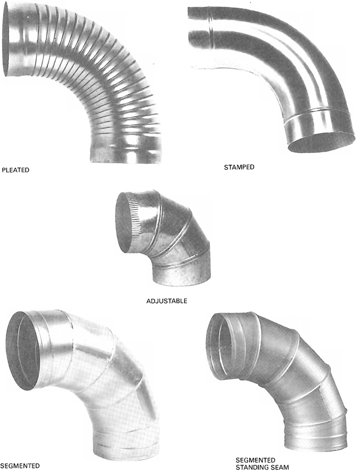
FIG. 3-3 ROUND DUCT ELBOWS
3.10
FIG. 3-4 90° TEES AND LATERALS
3.11
FIG. 3-5 CONICAL TEES
3.12Flat oval duct shall be provided where shown and as shown on the contract drawings.
Minimum duct wall thickness shall be as indicated in Table 3-4.
Reinforcement for flat sides of oval duct shall be of the same size and spacing interval as specified for rectangular duct or shall be provided to limit wall deflection to 3/4" (19 mm) and reinforcement deflection to 1/4" (6.4 mm).
Unless otherwise specified, joints and seams shall be similar to those indicated for round duct.
Fittings shall conform to the thickness schedules in Table 3-4, shall conform to the seam, joint, and connection arrangements permitted for round duct, and shall be reinforced to conform to paragraph 3.13.
The duct construction shall be capable of withstanding a pressure 50% greater than that of the assigned pressure class without structural failure or permanent deformation.
| Major Dimension Duct Width |
Spiral Seam Duct Gage |
Longitudinal Seam Duct Gage |
Gage of Fittings |
|---|---|---|---|
| to 24" | 24 | 20 | 20 |
| 25" to 36" | 22 | 20 | 20 |
| 37" to 48" | 22 | 18 | 18 |
| 49" to 60" | 20 | 18 | 18 |
| 61" to 70" | 20 | 16 | 16 |
| 71" and Up | 18 | 16 | 16 |
Duct wall deflection at atmospheric pressure, with reinforcements and connections in place, shall not exceed 1/4" (6.4 mm) on widths of 36" (914 mm) or less or 1/2" (13 mm) on greater widths. (See criteria in Section 7)
Supports shall conform to those permitted for rectangular duct, with the overall dimensions taken as references.
Flat oval duct combines the advantages of round duct and rectangular duct because it may fit in spaces where there is not enough room for round duct, and it can be joined using the techniques of round duct assembly.
Spiral flat oval duct is machine-made from round spiral lockseam duct and is available in varying sizes and aspect ratios. It can also be made with longitudinal seams.
Flat oval duct has considerably less flat surface that is susceptible to vibration and requires less reinforcement than a corresponding size of rectangular duct. The deflection of the flat oval duct under pressure is related to the flat span rather than the overall width of the duct.
Any round duct fitting can have an equivalent fitting made in flat oval. As in rectangular duct, a hard bend elbow denotes the bend in the plane of the duct width, whereas an easy bend elbow denotes the bend in the plane of the duct height. Any branch fitting can be made with the branch tap either round or flat oval. The tap of the flat oval fitting can be located anywhere on the circumference of the fitting body. If the diameter of a round tap is greater than the height of the flat oval body, a transition can be made from flat oval to round, providing an equivalent area at the base of the transition.
Flat oval duct is for positive pressure applications only unless special designs are used.
3.13
FIG. 3-6 FLAT OVAL DUCTS
3.14Unless otherwise designated, the term “flexible air duct” is used for all ducts classified by UL as either flexible air ducts or flexible connectors.
These provisions apply to ducts used for indoor comfort heating, ventilating, and air conditioning service. They do not apply to service for conveying particulates, corrosive fumes and vapors, high temperature air, corrosive or contaminated atmosphere, etc.
It is presumed that project specifications define the specific materials, pressure limits, velocity limits, friction rate, thermal conductivity, acoustical ratings, and other attributes.
When ducts must conform to NFPA Standard 90A or 90B, flexible ducts must be tested in accordance with Underwriters Laboratory’s Standard for Factory made Duct Materials, UL-181, and must be installed in accordance with the conditions of their UL listing. Separate installation limitations for flexible connectors and flexible ducts are identified in NFPA Standard 90A. By UL Standard 181, a flexible connector is defined as a flexible air duct not having certain flame penetration, puncture, and impact tests.
The minimum length of flexible duct should be used.
Bends shall be made with not less than 1 duct diameter centerline radius. Ducts should extend a few inches beyond the end of a sheet metal connection before bending. Ducts should not be compressed.
Ducts shall be located away from hot equipment such as furnaces and steam pipes to avoid excess temperature exposure.
Illustrations of accessories, sleeves, and collars are representative of classes of items. The use of components not precisely identical to these is acceptable.
If the application guidelines dictated by the flexible duct manufacturer are more stringent than the specifications in this manual, those of the manufacturer shall govern.
3.15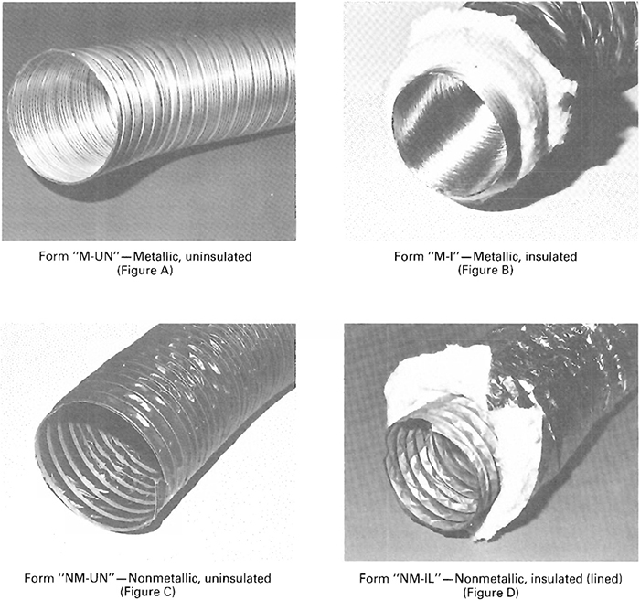
FIG. 3-7 TYPES OF FLEXIBLE DUCT
3.16The provisions for sealing ducts specified on page 1-8 apply. Adhesives shall be chemically compatible with materials they contact.
The ends of ducts shall be trimmed square before installation.
Collars to which flexible duct is attached shall be a minimum of 2" (51 mm) in length. Sleeves used for joining two sections of flexible duct shall be a minimum of 4" (102 mm) in length.
Collars and sleeves shall be inserted into flexible duct a minimum of 1" (25 mm) before fastening.
Metallic flexible duct shall be attached with at least three #8 sheet metal screws equally spaced around the duct’s circumference. Ducts larger than 12" in (305 mm) diameter shall have at least of five #8 sheet metal screws. Screws shall be located at least 1/2" (13 mm) from the duct end.
Non metallic flexible duct shall be secured to the sleeve or collar with a draw band. If the duct collar exceeds 12" (305 mm) in diameter the draw band must be positioned behind a bead on the metal collar.
Insulation and vapor barriers on factory-fabricated ducts shall be fitted over the core connection and shall also be secured with a draw band.
3.17These photographs depict typical accessories but do not represent all available accessories. Coincidence with proprietary features is unintentional. The standard is not intended to limit the selection or the development of accessories for use with flexible duct.
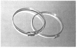
Figure A–Metal Clamp
Figure B–Nonmetallic Duct Clamp
Figure C–Collar (Dovetail)
Figure D–Collar (Spin-in, flared)
Figure E–Collar (Spin-in Straight)
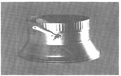
Figure F–Collar (Spin-in Conical)
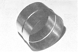
Figure G–4" sleeve
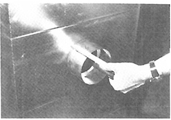
Figure H–Collar in duct min. 2"
3.18Flexible duct shall be supported at the manufacturer’s recommended intervals but at least every 5′ (1.5m). Maximum permissible sag is a 1/2 inch per foot (41.7 mm/m) of spacing between supports. A connection to another duct or to equipment is considered a support point.
Hanger or saddle material in contact with the flexible duct shall be wide enough so that it does not reduce the internal diameter of the duct when the supported section rests on the hanger or saddle material. In no case will the material contacting the flexible duct be less than 1" wide. Narrower hanger material may be used in conjunction with a sheet metal saddle that meets this specification. This saddle must cover one-half the circumference of the outside diameter of the flexible duct and fit neatly around the lower half of the duct’s outer circumference.
Factory-installed suspension systems that are integral to the flexible duct are acceptable for hanging when the manufacturer’s recommended procedures are followed.
Hangers shall be adequately attached to the building structure.
To avoid tearing the vapor barrier, do not support the entire weight of the flexible duct on any one hanger during installation. Avoid contacting the flexible duct with sharp edges of the hanger material. Damage to the vapor barrier may be repaired with approved tape. If the internal core is penetrated, replace the flexible duct or treat the tear as a connection.
Terminal devices connected by flexible duct shall be supported independently of the flexible duct.
3.19
FIG. 3-9 FLEXIBLE DUCT SUPPORTS
3.20
FIG. 3-10 FLEXIBLE DUCT SUPPORTS
3.21Flexible air ducts have rectangular UL labels attached every 10′ (3.05 m); flexible connectors have round labels every 10′ (3.05 m). UL, NFPA, and most codes make distinctions between these two products in their limits of application. Connectors are more restricted and are currently limited to 14" (4.27 m) of installed length. Regulations governing these forms of duct should be checked especially for floor penetrations, ceiling air plenums, and fire rated floor-ceiling or roof-ceiling assemblies.
These installation provisions were prepared for round ducts; however, they may also be usable for flexible flat oval ducts.
Some types of flexible duct have received listings as components of fan unit or air terminal unit systems, and they may be governed independently by the conditions of those listings.
The designer should consult the following references when considering the use of flexible ducts:
UL Standard 181
NFPA Standards 90A and 90B
UL Gas and Oil Equipment Directory
UL Fire Resistance Directory
ASTM Standard E96, Water Vapor Transmission of Materials in Sheet Form, American Society of Testing Materials
ASTM Standard E477, Duct Liner Materials and Prefabricated Silencer for Acoustical Performance, American Society of Testing Materials
ADC Flexible Air Duct Test Code FD-72, Rl, Air Diffusion Council (covering thermal, acoustical and friction ratings)
TIMA Test Method AHS 151-76T, Dynamic Thermal Performance of Air Handling Systems, Thermal Insulation Manufacturers Association
The most common metallic duct is aluminum; however, galvanized steel and stainless steel varieties are available. Nonmetal ducts are available in a wide variety of materials and nominal shape-retaining reinforcements. Machines for producing the ducts are available from several suppliers.
Flexible ducts may come to the installer in compressed form in a variety of lengths. Their length can be determined by a measurement taken with a 25 lb. (11.3 Kg) axial load used to extend the duct. Repeated flexure of metallic ducts will probably result in fatigue stress cracking. Sections S3.23 and S3.24 contain statements that ducts “should” have minimum length and “should not” be compressed. “Should” is used instead of “must” in these instances because some discretionary judgement is necessary. Compressing duct increases first cost and friction loss. The minimum length refers to the practical route between connection points but not to the degree that the material is overstressed or to the degree that all available stretch is removed. SMACNA discourages the practice of providing excess length in case of future building modifications.
3.22This installation standard is applicable to ducts placed in or beneath concrete floors or in areas free from vehicle traffic.
Materials shall conform to the project specifications.
Ducts shall be located as shown on the contract drawings.
The duct contractor shall provide:

FIG. 3-11 TYPICAL UNDERSLAB DUCT
3.24
FIG. 3-12 ANCHORS FOR DUCT ENCASEMENT
3.25Materials commonly used for this application include galvanized steel, vinyl chloride-coated steel, and stainless steel. Glass fiber-reinforced resin, asbestos, cement, tile, and other nonmetal ducts are also used. Ducts are not generally deemed to be or required to be waterproof. Ducts should always be above the water table. The designer should carefully evaluate the exposure to moisture or ground water and require vapor barriers, sumps, porous fill, and subsoil drainage pipe as necessary. CSI Specification 02410 provides useful references for subsoil drainage. The top of drain tile should be below the bottom of the duct.
Corrosion resistance is an important characteristic of both in-slab and under-slab ducts. The Portland Cement Association has guidelines for protection of metals in contact with concrete. ASHRAE’s Systems Handbook addresses the corrosion of materials in soil environments.
The strength of round ducts makes them the preferred shape for underground application. Round duct wall thicknesses in these standards are generally acceptable for below-grade installation. Ribbed or corrugated styles have additional crushing strength. Temporary internal supports can be appropriate at times. Ducts should have continuous bedding.
Ducts to be embedded in concrete are subject to floating and they must be restrained. The first pour should be the base support for the duct and anchors should be included. Twelve gage (2.68 mm) wire, 16 gage (2.75 mm) straps, or other appropriate ties should be specified for hold-down.
Ducts buried in sand or pea gravel are not known to float. Porous fill and earth fill should not be dumped directly on ducts in trenches. Fill should be firmly but not heavily tamped under and around the duct. The first foot of fill should be shovelled on top of the duct. Fill should not contain stones larger than 2" (51 mm).
3.26Rigid round, rectangular, and flat oval metal ducts shall be installed with support systems indicated in Tables 4-1 to 4-3 and Figures 4-1 to 4-8. They shall be installed as required to maintain alignment. Horizontal ducts shall have a support within two feet (0.61 m) of each elbow and within four feet of each branch intersection. (Upper attachments to structures shall have an allowable load not more than one-fourth of the failure (proof test) load but are not limited to the specific methods shown here.
The duct hanging system is composed of three elements, the upper attachment to the building, the hanger itself, and the lower attachment to the duct. The manufacturer’s load ratings and application data should be followed for all devices and materials.
Concrete inserts must be installed before the concrete is poured. They are used primarily where the duct layout is simple and there is enough lead time to determine accurate placement. The simplest insert is a piece of bent flat bar. Manufactured inserts are available individually or in long lengths; the latter are generally used where many hangers will be installed in a small area, or where individual inserts cannot be precisely spotted at the time of placing the concrete.
Concrete fasteners are installed after the concrete has been poured and the forms have been removed. Their application allows greater flexibility than concrete inserts because their exact location can be determined after all interferences between the various trades’ work have been coordinated.
There are several variations of powder-actuated fasteners, which are placed by an explosive charge. These fasteners should not be used in certain lightweight aggregate concretes, or in slabs less than 4 inches (107 mm) thick.
Expanding concrete anchors should be made of steel. Nonferrous anchors tend to creep with vibration. Holes for expanding fasteners are drilled either by a carbide bit or by teeth on the fastener itself. The expansion shield is “set” by driving it into the hole and expanding it with the conical plug. The expansion nail is a lighter duty fastener. Powder-actuated fasteners are popular for smaller ducts.
Several types of beam clamps are available. Some should be used with a retaining clip. Powder-actuated fasteners may also be used on steel. Welded studs may be installed using special welding equipment. Certain manufactured devices that are driven onto the flange will support either a rod or a band type hanger.
Many office buildings are now built with a cellular steel deck that carries the electrical and communication systems and is covered with concrete fill. The wiring in the cells and the concrete above the deck preclude the use of fasteners, such as sheet metal screws, that must pierce the deck. Some manufacturers of this type of deck now offer an integral hanging system. In cases where there are no integral hangers at the required hanging points, install the rod or strap hangers before concrete placement, or install welded studsafter concrete placement. In all cases, the upper attachments to the decking should be in place before the application of fireproofing materials.
Upper attachment methods should be selected with care. A safety factor of 4 or 5 (based on ultimate failure) is practical unless it can be shown that few unpredictable variables exist and that quality control is disciplined.
Hangers are usually strips of galvanized steel or round steel rod. For hangers made of round steel rod, use uncoated hot-rolled steel except where the installation is in a corrosive atmosphere. Where corrosion is a problem, hanger rods should be electro-galvanized, all-thread rods or hot-dipped galvanized rods with their threads painted after installation.
4.1The lower attachment is the connection between the hanger and the duct section. Fasteners that penetrate the duct may be sheet metal screws, blind rivets, or self-tapping metal screws.
A straight duct section is actually a box section beam of considerable strength. As in many structures, the joint is the weakest point, so that is where the support is. Duct joints, however, are normally strong enough to permit maximum hanger spacing at 8 (2.44) or 10 foot (3.05 m) intervals, even with one or two intermediate joints. Very wide ducts require closer hanger spacing in order to limit individual hanger loads to safe values. They also require intermediate hangers to prevent the upper portion of the duct from sagging.
Trapeze members must be selected with careful attention to the position of the loads on the horizontal bar. Load analysis is discussed in the notes for Figures 4-4 and 4-5.
Rectangular risers should be supported by angles or channels secured to the sides of the duct with welds, bolts, sheet metal screws, or blind rivets. Here again, for ducts over 30 inches (762 mm) wide, caution must be used in fastening the support to the sheet because the expansion of the sheet due to internal pressures will tend to tear the fasteners out. Riser support intervals should be at one or two story intervals, i.e., 12 feet (3.66 m) to 24 feet (7.32 m), as suitable for loading. Another method is to support the riser by its reinforcing. The load can be transferred to the riser support by angles or by rods.
The selection of a hanging system should not be taken lightly not only because it involves a significant portion of the erection labor, but also because an inadequate hanging system can be disastrous. In any multiple hanger system, the failure of one hanger transfers that its load to adjacent hangers. If one of these fails, an even greater load is transferred to the next. The result is a cascading failure in which an entire run of duct might fall.
There are many hanger alternatives, especially in the upper attachments. Besides structural adequacy, the contractor’s choice of hanging system must also take into account the particulars of the building structure, the skills of the workmen, the availability of tooling, and the recommendations of the fastener manufacturer. Because of these variables, it is suggested that the hanging system be the contractor’s choice, subject to the approval of the mechanical engineer.
Figures in this manual show typical hanger constructions. When special conditions require high safety factors or the ability to withstand vibrations, individual concrete or steel attachments can be specified to be capable of supporting test loads equal to the minimum rating listed when they are tested in accordance with methods described by Underwriters’ Laboratory, Inc., for Pipe Hanger Equipment, Bulletin UL 203, latest edition. See pages 3-19 to 3-21 for support of flexible duct.
The supports discussed here are not seismicly qualified. Refer to SMACNA’s Seismic Restraint Manual for additional reinforcement required by earthquake hazards.
4.2
FIG. 4-1 HANGER ATTACHMENTS TO STRUCTURES
4.3
FIG. 4-2 UPPER ATTACHMENT DEVICES - TYPICAL
4.4
FIG. 4-3 UPPER ATTACHMENTS - TYPICAL
4.5| MAXIMUM HALF OF DUCT PERIMETER |
Pair at 10 ft Spacing | Pair at 8 ft Spacing | Pair at 5 ft Spacing | Pair at 4 ft Spacing | |||||
|---|---|---|---|---|---|---|---|---|---|
| STRAP | WIRE/ ROD |
STRAP | WIRE/ ROD |
STRAP | WIRE/ ROD |
STRAP | WIRE/ ROD |
||
| P/2 = 30″ | 1″ × 22 ga. | 10 ga. (.135″) | 1″ × 22 ga. | 10 ga. (.135″) | 1″ × 22 ga. | 12 ga. (.106″) | 1″ × 22 ga. | 12 ga. (.106″) | |
| P/2 = 72″ | 1″ × 18 ga. | 3/8″ | 1″ × 20 ga. | 1/4″ | 1″ × 22 ga. | 1/4″ | 1″ × 22 ga. | 1/4″ | |
| P/2 = 96″ | 1″ × 16 ga. | 3/8″ | 1″ × 18 ga. | 3/8″ | 1″ × 20 ga. | 3/8″ | 1″ × 22 ga. | 1/4″ | |
| P/2 = 120″ | 1 1/2″ × 16 ga. | 1/2″ | 1″ × 16 ga. | 3/8″ | 1″ × 18 ga. | 3/8″ | 1″ × 20 ga. | 1/4″ | |
| P/2 = 168″ | 1 1/2″ × 16 ga. | 1/2″ | 1 1/2″ × 16 ga. | 1/2″ | 1″ × 16 ga. | 3/8″ | 1″ × 18 ga. | 3/8″ | |
| P/2 = 192″ | Not Given | 1/2″ | 1 1/2″ × 16 ga. | 1/2″ | 1″ × 16 ga. | 3/8″ | 1″ × 16 ga. | 3/8″ | |
| P/2 = 193″ up | SPECIAL ANALYSIS REQUIRED | ||||||||
| WHEN STRAPS ARE LAP JOINED USE THESE MINIMUM FASTENERS: | SINGLE HANGER MAXIMUM ALLOWABLE LOAD | ||||||||
| STRAP | WIRE OR ROD (Dia.) | ||||||||
| 1″ × 18, 20, 22 ga. -two #10 or one 1/4″ bolt | 1″ × 22 ga.- 260 lbs. | 0.106″- 80 lbs. | |||||||
| 1″ × 16 ga. -two 1/4″ dia. | 1″ × 20 ga.- 320 lbs. | 0.135″- 120 lbs. | |||||||
| 1 1/2″ × 16 ga. -two 3/8″ dia. | 1″ × 18 ga.- 420 lbs. | 0.162″- 160 lbs. | |||||||
| Place fasteners in series, not side by side. | 1″ × 16 ga.- 700 lbs. | 1/4″- 270 lbs. | |||||||
| 1 1/2″ × 16 ga.- 1100 lbs. | 3/8″- 680 lbs. | ||||||||
| 1/2″- 1250 lbs. | |||||||||
| 5/8″- 2000 lbs. | |||||||||
| 3/4″- 3000 lbs. | |||||||||
NOTES:
| MAXIMUM HALF OF DUCT PERIMETER |
Pair at 3 m Spacing | Pair at 2.4 m Spacing | Pair at 1.5 m Spacing | Pair at 1.2 m Spacing | |||||
|---|---|---|---|---|---|---|---|---|---|
| STRAP | WIRE/ ROD |
STRAP | WIRE/ ROD |
STRAP | WIRE/ ROD |
STRAP | WIRE/ ROD |
||
| P/2 = 760 | 25.4 × 0.85 | 3.4 | 25.4 × 0.85 | 3.4 | 25.4 × 0.85 | 2.7 | 25.4 × 0.85 | 2.7 | |
| P/2 = 1830 | 25.4 × 1.31 | 9.5 | 25.4 × 1.00 | 6.4 | 25.4 × 0.85 | 6.4 | 25.4 × 0.85 | 6.4 | |
| P/2 = 2440 | 25.4 × 1.61 | 9.5 | 25.4 × 1.31 | 9.5 | 25.4 × 1.00 | 9.5 | 25.4 × 0.85 | 6.4 | |
| P/2 = 3050 | 38.1 × 1.61 | 12.7 | 25.4 × 1.61 | 9.5 | 25.4 × 1.31 | 9.5 | 25.4 × 1.00 | 6.4 | |
| P/2 = 4270 | 38.1 × 1.61 | 12.7 | 38.1 × 1.61 | 12.7 | 25.4 × 1.61 | 9.5 | 25.4 × 1.31 | 9.5 | |
| P/2 = 4880 | Not Given | 12.7 | 38.1 × 1.61 | 12.7 | 25.4 × 1.61 | 9.5 | 25.4 × 1.61 | 9.5 | |
| P/2 = More | SPECIAL ANALYSIS REQUIRED | ||||||||
| WHEN STRAPS ARE LAP JOINED USE THESE MINIMUM FASTENERS: | SINGLE HANGER MAXIMUM ALLOWABLE LOAD | ||||||||
| STRAP | WIRE OR ROD (Dia.) | ||||||||
| 25.4 × 1.31, 1.00, 0.85 mm - one 6.4 bolt | 25.4 × 0.85 - 118 Kg | 2.7 - 36 Kg | |||||||
| 25.4 × 1.61 mm - two 6.4 bolts | 25.4 × 1.00 - 145 Kg | 3.4 - 54 Kg | |||||||
| 38.1 × 1.61 mm - two 9.5 bolts | 25.4 × 1.31 - 191 Kg | 4.1 - 73 Kg | |||||||
| Two bolts must be in series, not side by side. | 25.4 × 1.61 - 318 Kg | 6.4 - 122 Kg | |||||||
| 38.1 × 1.61 - 500 Kg | 9.5 - 308 Kg | ||||||||
| 12.7 - 567 Kg | |||||||||
| 15.9 - 907 Kg | |||||||||
| 19.1 - 1360 Kg | |||||||||
NOTES:
| Dia. | Maximum Spacing | Wire Dia. | Rod | Strap |
|---|---|---|---|---|
| 10″ dn 250 mm dn |
12′ 3.7 m |
One 12 ga. One 2.75 mm |
1/4″ 6.4 mm |
1″ × 22 ga. 25.4 × 0.85 mm |
| 11-18″ | 12′ | Two 12 ga. or One 8 ga. |
1/4″ | 1″ × 22 ga. |
| 460 mm | 3.7 m | One 4.27 mm | 6.4 mm | 25.4 × 0.85 mm |
| 19-24″ 610 mm |
12′ 3.7 m |
Two 10 ga. Two 3.51 mm |
1/4″ 6.4 mm |
1″ × 22 ga. 25.4 × 0.85 mm |
| 25-36″ 900 mm |
12′ 3.7 m |
Two 8 ga. Two 2.7 mm |
3/8″ 9.5 mm |
1″ × 20 ga. 25.4 × 1.00 mm |
| 37-50″ 1270 mm |
12′ 3.7 m |
 |
Two 3/8″ Two 9.5 mm |
Two 1″ × 20 ga. (2) 25.4 × 1.00 mm |
| 51-60″ 1520 mm |
12′ 3.7 m |
|
Two 3/8″ Two 9.5 mm |
Two 1″ × 18 ga. (2) 25.4 × 1.31 mm |
| 61-84″ 2130 mm |
12′ 3.7 m |
|
Two 3/8″ Two 9.5 mm |
Two 1″ × 16 ga. (2) 25.4 × 1.61 mm |
NOTES:

FIG. 4-4 LOWER HANGER ATTACHMENTS
4.9| ANGLES | CHANNELS | |||||||||||||||
|---|---|---|---|---|---|---|---|---|---|---|---|---|---|---|---|---|
| Length | 1 × 1 × 16 ga. | 1 × 1 × 1/8″ | 1-1/2 × 1-1/2 × 16 ga. | 1-1/2 × 1-1/2 × 1/8″ | 1-1/2 × 1-1/2 × 3/16″ | 1-1/2 × 1-1/2 × 1/4″ or 2 × 2 × 1/8″ | 2 × 2 × 3/16″ | 2 × 2 × 1/4″ | 2-1/2 × 2-1/2 × 3/16″ | 2-1/2 × 2-1/2 × 1/4″ | 3 × 3 × 1/4″ | 4 × 4 × 1/4″ | 3 × 4.1 LBS. | 3 × 6.0 LBS. | 4 × 5.4 LBS. | |
| 18″ | 80 | 150 | 180 | 350 | 510 | 650 | 940 | 1230 | 1500 | 1960 | ||||||
| 24″ | 75 | 150 | 180 | 350 | 510 | 650 | 940 | 1230 | 1500 | 1960 | ||||||
| 30″ | 70 | 150 | 180 | 350 | 510 | 650 | 940 | 1230 | 1500 | 1960 | ||||||
| 36″ | 60 | 130 | 160 | 340 | 500 | 620 | 920 | 1200 | 1480 | 1940 | ||||||
| 42″ | 40 | 110 | 140 | 320 | 480 | 610 | 900 | 1190 | 1470 | 1930 | ||||||
| 48″ | - | 80 | 110 | 290 | 450 | 580 | 870 | 1160 | 1440 | 1900 | ||||||
| 54″ | - | - | - | 250 | 400 | 540 | 840 | 1120 | 1400 | 1860 | ||||||
| 60″ | - | - | - | 190 | 350 | 490 | 780 | 1060 | 1340 | 1800 | ||||||
| 66″ | - | - | - | 100 | 270 | 400 | 700 | 980 | 1260 | 1720 | ||||||
| 72″ | - | - | - | - | 190 | 320 | 620 | 900 | 1180 | 1640 | ||||||
| 78″ | - | - | - | - | - | 210 | 500 | 790 | 1070 | 1530 | ||||||
| 84″ | - | - | - | - | - | - | 380 | 660 | 940 | 1400 | 2310 | 4680 | 4650 | 5980 | 9080 | |
| 96″ | - | - | - | - | - | - | - | 320 | 600 | 1060 | 1970 | 4340 | 3870 | 4950 | 8740 | |
| 108″ | - | - | - | - | - | - | - | - | - | - | 2510 | 7240 | 5760 | 7780 | 15650 | |
| 120″ | - | - | - | - | - | - | - | - | - | - | 1220 | 5950 | 4120 | 5930 | 13200 | |
| 132″ | - | - | - | - | - | - | - | - | - | - | - | 4350 | 2540 | 3920 | 10820 | |
| 144″ | - | - | - | - | - | - | - | - | - | - | - | 2420 | - | 2000 | 8330 | |
| SECTION PROPERTIES |
Ix | .012 | .022 | .041 | .078 | .110 | .139/ .190 |
.272 | .348 | .547 | .703 | 1.24 | 3.04 | 1.66 | 2.07 | 3.85 |
| A | .12 | .234 | .180 | .359 | .527 | .688/ .484 |
.715 | .938 | .902 | 1.19 | 1.44 | 1.94 | 1.21 | 1.76 | 1.59 | |
| Z | .016 | .031 | .037 | .072 | .104 | .130/ .130 |
.190 | .247 | .303 | .394 | 0.577 | 1.05 | 1.10 | 1.38 | 1.93 | |
| LB/LF | .44 | .80 | .66 | 1.23 | 1.80 | 2.34/ 1.65 |
2.44 | 3.19 | 3.07 | 4.10 | 4.9 | 6.6 | 4.1 | 6.0 | 5.4 | |
IT IS ASSUMED THAT STEEL MATERIAL WITH A YIELD STRENGTH OF 25,000 PSI OR GREATER IS USED.
LOADS ABOVE ASSUME THAT A HANGER ROD IS 6” MAX. DISTANCE FROM DUCT SIDE FOR LENGTHS 96” OR LESS AND 3” FOR GREATER LENGTHS.
IF THE ROD IS 2” AWAY FROM THE DUCT THE ALLOWABLE LOAD INCREASES SIGNIFICANTLY.
STRUCTURAL STEEL SHAPES THAT HAVE EQUIVALENT Z PROPERTIES MAY BE USED AS ALTERNATIVES. Z IS IN IN3. Ix IS IN IN4.
See Fig. 4-5 for load calculation method.
See Table 4-1 for rod and strap load limits.
| DIMENSIONS OF EQUAL LEG ANGLES IN MILLIMETERS | CHANNELS | |||||||||||||||
|---|---|---|---|---|---|---|---|---|---|---|---|---|---|---|---|---|
| Length | 25.4 × 1.61 | 25.4 × 3.2 | 38.1 × 1.61 | 38.1 × 3.2 | 38.1 × 4.8 | 38.1 × 6.4 or 51 × 3.2 |
51 × 3.8 | 51 × 6.4 | 63.5 × 4.8 | 63.5 × 6.4 | 76 × 6.4 | 102 × 6.4 | 76 × 1.9 | 76 × 2.7 | 102 × 2.5 | |
| 450 | 36 | 68 | 81 | 159 | 231 | 295 | 426 | 558 | 680 | 889 | ||||||
| 600 | 34 | 68 | 81 | 159 | 231 | 295 | 426 | 558 | 680 | 889 | ||||||
| 760 | 32 | 68 | 81 | 159 | 231 | 295 | 426 | 558 | 680 | 889 | ||||||
| 900 | 27 | 59 | 72 | 154 | 227 | 281 | 417 | 549 | 671 | 880 | ||||||
| 1060 | 18 | 50 | 63 | 145 | 218 | 277 | 408 | 540 | 667 | 875 | ||||||
| 1220 | - | 36 | 50 | 132 | 204 | 263 | 395 | 526 | 653 | 862 | ||||||
| 1370 | - | - | - | 113 | 181 | 245 | 381 | 508 | 635 | 844 | ||||||
| 1520 | - | - | - | 86 | 159 | 222 | 354 | 480 | 608 | 818 | ||||||
| 1670 | - | - | - | 45 | 86 | 181 | 318 | 444 | 571 | 780 | ||||||
| 1830 | - | - | - | - | - | 145 | 281 | 408 | 535 | 744 | ||||||
| 2010 | - | - | - | - | - | 95 | 227 | 358 | 485 | 694 | ||||||
| 2130 | - | - | - | - | - | - | 454 | 299 | 426 | 635 | 1048 | 2123 | 2109 | 2713 | 4119 | |
| 2440 | - | - | - | - | - | - | - | 145 | 272 | 480 | 894 | 1969 | 1755 | 2245 | 3964 | |
| 2740 | - | - | - | - | - | - | - | - | - | - | 1139 | 3284 | 2613 | 3529 | 7010 | |
| 3050 | - | - | - | - | - | - | - | - | - | - | 553 | 2699 | 1869 | 2690 | 5987 | |
| 3350 | - | - | - | - | - | - | - | - | - | - | - | 1973 | 1152 | 1778 | 4908 | |
| 3660 | - | - | - | - | - | - | - | - | - | - | - | 1098 | - | 907 | 3778 | |
| SECTION PROPERTIES | Ix | .494 | .906 | 1.69 | 3.21 | 4.53 | 3.72/7.82 | 11.2 | 14.3 | 22.5 | 28.9 | 51.0 | 125 | 68.3 | 85.2 | 158 |
| A (mm2) | 77.4 | 151 | 116 | 232 | 340 | 444/312 | 4.61 | 605 | 582 | 768 | 929 | 1252 | 781 | 1136 | 1026 | |
| Z | .262 | .508 | .606 | 1.18 | 1.70 | 2.13 | 3.11 | 4.05 | 4.97 | 6.46 | 9.46 | 17.2 | 18.0 | 22.6 | 31.6 | |
| Kg/m | .65 | 1.20 | .98 | 1.83 | 2.68 | 3.48/2.46 | 3.63 | 4.75 | 4.57 | 6.10 | 7.29 | 9.82 | 6.10 | 8.93 | 8.04 | |
IT IS ASSUMED THAT STEEL MATERIAL WITH A YIELD STRENGTH OF 172.4 MPA OR GREATER IS USED.
LOADS ABOVE ASSUME THAT A HANGER ROD IS 152 MM MAX. DISTANCE FROM DUCT SIDE FOR LENGTHS 2440 MM OR LESS AND 76 MM FOR GREATER LENGTHS.
IF THE ROD IS 51 MM AWAY FROM THE DUCT THE ALLOWABLE LOAD INCREASES SIGNIFICANTLY.
STRUCTURAL STEEL SHAPES THAT HAVE EQUIVALENT Z PROPERTIES MAY BE USED AS ALTERNATIVES. Z IS IN 103 MM3. IX IS IN 104 MM3.
See Fig. 4-5 for load calculation method.
See Table 4-1 for rod and strap load limits.

FIG. 4-5 TRAPEZE LOAD DIAGRAM
4.12
FIG. 4-6 LARGE DUCT SUPPORT
4.13
FIG. 4-7 RISER SUPPORTS - FROM FLOOR
4.14
FIG. 4-7M RISER SUPPORTS - FROM FLOOR
4.15
FIG. 4-8 SUPPORTS FROM WALL
4.16
FIG. 4-8M SUPPORTS FROM WALL
4.17
FIG. 4-9 RISER SUPPORT - FROM FLOOR
4.18
FIG. 4-10 HVAC UNIT SUSPENSION
4.19 4.20Among the deliberations that designers should consider in the selection of louvers, rooftop ducts, curbs, ventilators, supports, and other components are the following.
Information on air flow pressure loss standard stock sizes, strength, corrosion, comparative cost and much other data on perforated metals is available from the Industrial Perforators Association. Some perforated metals have the appearance of wire mesh screens.
Similar data for bird screen, insect screen and other meshes for wire cloth is available from the American Wire Cloth Institute and its members.
5.1
FIG. 5-1 LOUVERS AND SCREENS
5.2
FIG. 5-1M LOUVERS AND SCREENS
5.3
FIG. 5-2 LOUVER FREE AREA CALCULATION
5.4Each installation of a roof-mounted HVAC unit or roof-supported duct involves customized design requirements. The construction details and recommendations here are therefore advisory and depend on contract documents for clarification. Openings in roofs require coordination of the architectural, structural, mechanical, and electrical contract drawings. The height of equipment and ducts above the roof level may be influenced by snow loading, snow drifting, and wind loading as well as esthetic considerations. Designers must specify constructions appropriate for the specific locality and circumstances.
All ducts that are not watertight through the use of welded constructions or protective shields and are exposed directly to weather and solar radiation should have secure, watertight mechanical connections and receive exterior duct sealant treatment as defined in Section 1.9(h).
Exterior duct sealant treatment should consist of applying products marketed specifically as forming a positive airtight and watertight seal, bonding well to the metal involved, remaining watertight with metal movement, and having a service temperature range of -30°F (-34°C) to 175°F (79°C). If exposed to direct sunlight it should also be ultraviolet ray- and ozone-resistant or should, after curing, be painted with a compatible coating that provides these plus weather resistance. The term sealant is not limited to materials of adhesive or mastic nature, but is inclusive of tapes and combinations of woven fabric strips and mastics. Asphalt-based compounds should not be used for sealing ducts.
Duct systems should not be pressurized until the sealant has had time to cure. Follow the sealant manufacturer’s recommendations on curing.
Unless otherwise prescribed by the HVAC equipment manufacturer, ducts should be flanged for attachment to equipment with mechanical fastening plus exterior duct sealant. Typical connections are shown in Figure 5-3. The attachment method should accommodate disconnection if this is required for routine maintenance of the equipment.
Where vibration isolation material is required at the connection of ducts to equipment, such material should be impervious to water. Ducts should be supported to avoid the transfer of duct weight across flexible connections.
Roof penetrations by ducts should have curbs. Ducts that are interrupted at the curb should overhang the top of the curb or be flashed to divert water over the curb. Ducts that are continuous through the curb should have flashing that slopes over the curb and is sealed to the duct with caulking or a suitable tape. Adequate clearances between ducts and roof penetration openings should be provided. See Figure 5-4.
Curbs may be supplied with rooftop units or provided independently. The equipment manufacturer may outline flashing methods, structural opening requirements, sealing techniques, etc., which must be coordinated with project construction. With considerable pitch in the roof, a subbase may be required to adapt to a pre-engineered curb. Furthermore, curb mountings may incorporate vibration isolation features.
All penetrations into ducts should be watertight. Duct reinforcements and supports attached to the duct should have external sealant at points of penetrations. Attach supports with a minimum number of duct penetrations.
Horizontal ducts should be pitched and provided with drainage outlets as illustrated by the system designer.
If airtight, waterproof flexible insulation jackets are applied on positive pressure ducts, the installation should accommodate some duct leakage; ducts are not completely airtight.
When moving rooftop units across the roof, handle them in a manner to prevent roof damage.
Supports for ducts should be as indicated in Figure 5.4. If the support does not rest on a cap-flashed curb, the penetration of the roof membrane should have base flashing and umbrella flashing.
Pitch pockets require periodic maintenance and are not permanently watertight. They are not recommended.
Designers should carefully consider the proximity of intakes to exhausts and the possibility of drawing in contaminated air. The direction and elevation of discharges may be controlled by codes or standards such as NFPA-89M, 90A, 91, 96, 204 or 211.
5.5
FIG. 5-3 ROOFTOP DUCT INSTALLATION
5.6
FIG. 5-4 EQUIPMENT AND DUCT SUPPORT FLASHING
5.7
FIG. 5-5 RECTANGULAR GOOSENECK
5.8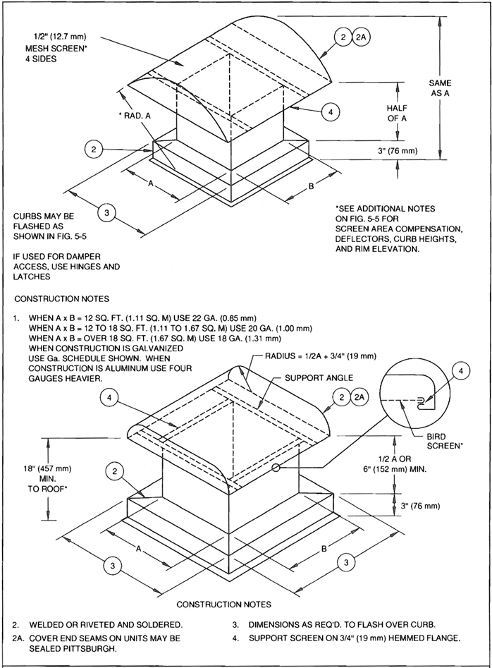
FIG. 5-6 INTAKE OR EXHAUST VENTILATORS
5.9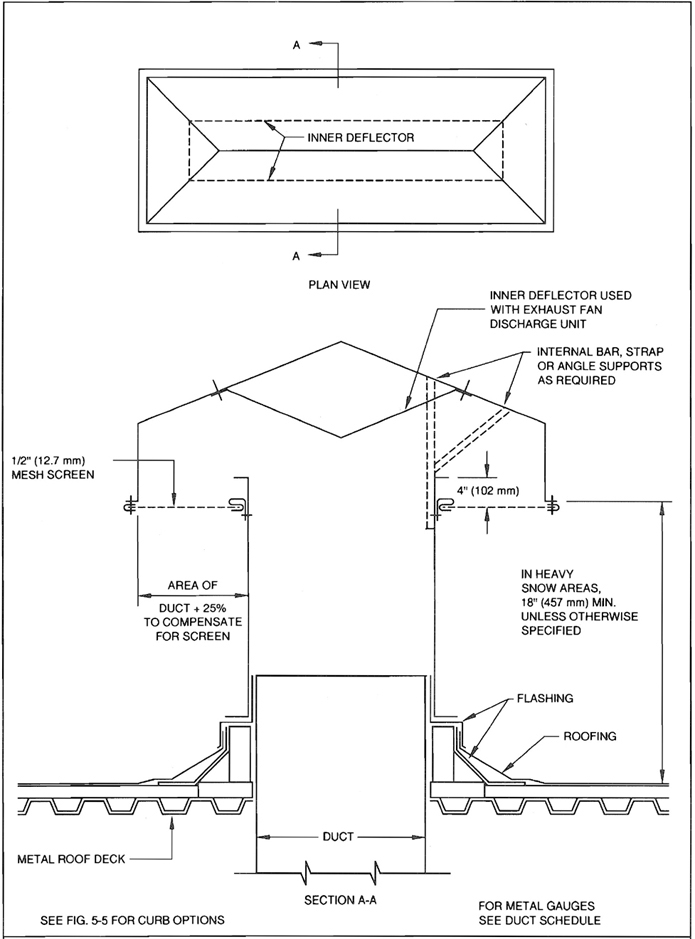
FIG. 5-7 LARGE INTAKE OR EXHAUST VENTILATORS
5.10Unless details are shown otherwise on contract drawings, provide casings and plenums of the designated pressure classification as required by this standard.
Submit details selected from the illustrated alternatives for approval of the contracting authority. When equivalent construction is proposed as substitution, clearly identify the substitution. Use construction appropriate for the pressure classification.
All casing on the suction side of the fan shall be of 2″ w.g. (500 Pa) pressure classification. Casing on fan discharge shall be of the designated pressure class.
All joints, seams, connections, and abutments to the building structure shall be sealed with suitable compounds or gaskets.
Drains shall have water seals not less than 2″ w.g. (500 Pa) greater than the maximum operating pressure in the chamber.
Pipe penetrations shall be sealed to prevent air leakage and condensation movement through the seal.
Casing material shall be of the same commercial grades as for ducts except that G90 coated galvanized steel shall be used in all chambers with moisture present.
Metal drain pans shall be of G90 coated galvanized steel.
All welds on casing interiors shall be painted.
Close-off or safing sheets and strips shall be of G90 galvanized steel of thickness not less than that of the duct widths and shall be securely attached. They shall not be used for structural support of equipment.
Casings and plenums shall be constructed to withstand 133% of the rated pressure without structural failure. Wall and roof deflections at the rated pressure shall not exceed 1/8″ per foot (0.97 mm/m) of width.
Casing for negative pressures greater than 3″ w.g. (750 Pa) may be constructed in accordance with the SMACNA Rectangular Industrial Duct Construction Standards.
6.1
FIG. 6-1 BUILT-UP STANDING SEAM CASING
6.2
FIG. 6-1M BUILT-UP STANDING SEAM CASING
6.3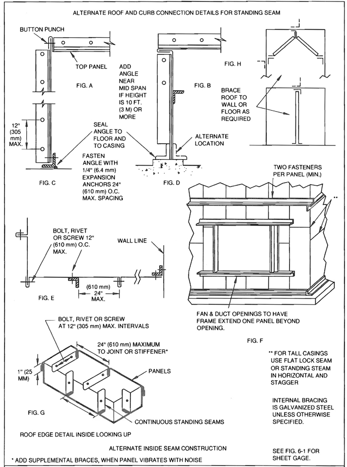
FIG. 6-2 STANDING SEAM CASINGS
6.4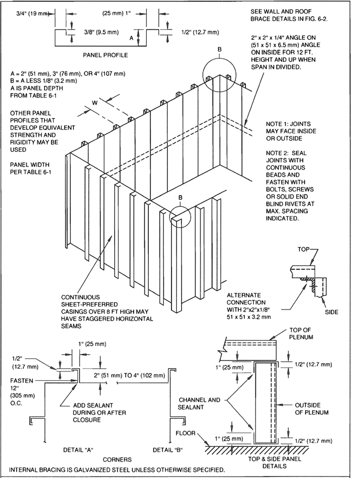
FIG. 6-3 ALTERNATE CASING CONSTRUCTION
6.5| MAXIMUM ALLOWABLE PANEL WIDTH FOR A GIVEN PANEL GAGE, SPAN, AND LOAD CLASS | |||||||
|---|---|---|---|---|---|---|---|
| LOAD CLASS (″ W.G. STATIC) | |||||||
| Span | Panel Gage |
Depth | 2″ (500 Pa) | 3″ (750 Pa) | 4″ (1000 Pa) | 6″ (1500 Pa) | 10″ (2500 Pa) |
| 6 Feet (1.8 Meters) |
#22 (0.85 mm) | 2″ (51 mm) | 20″ (508 mm) | 14″ (356 mm) | 12″ (305 mm) | - | - |
| #22 | 3″ (76 mm) | 20″ (508 mm) | 16″ (406 mm) | 14″ (356 mm) | - | - | |
| #22 | 4″ (102 mm) | 22″ (559 mm) | 16″ (406 mm) | 14″ (356 mm) | 12″ (305 mm) | - | |
| #20 (1.00 mm) | 2″ | 24″ (610 mm) | 18″ (457 mm) | 16″ (406 mm) | 12″ (305 mm) | - | |
| #20 | 3″ | 24″ | 20″ (508 mm) | 18″ (457 mm) | 14″ (356 mm) | - | |
| #20 | 4″ | 24″ | 20″ (508 mm) | 18″ (457 mm) | 14″ (356 mm) | - | |
| #18 (1.31 mm) | 2″ | 24″ | 24″ (610 mm) | 22″ (559 mm) | 16″ (406 mm) | 12″ (305 mm) | |
| #18 | 3″ | 24″ | 24″ | 24″ (610 mm) | 18″ (457 mm) | 14″ (356 mm) | |
| #18 | 4″ | 24″ | 24″ | 24″ | 20″ (508 mm) | 14″ | |
| #16 (1.61 mm) | 2″ | 24″ | 24″ | 24″ | 22″ (559 mm) | 16″ (406 mm) | |
| #16 | 3″ | 24″ | 24″ | 24″ | 24″ (610 mm) | 18″ (457 mm) | |
| #16 | 4″ | 24″ | 24″ | 24″ | 24″ | 18″ | |
| 8 Feet (2.4 Meters) |
#22 (0.85 mm) | 2″ (51 mm) | 16″ (406 mm) | 12″ (305 mm) | - | - | - |
| #22 | 3″ (76 mm) | 18″ (457 mm) | 14″ (356 mm) | 12″ (305 mm) | - | - | |
| #22 | 4″ (102 mm) | 20″ (508 mm) | 16″ (406 mm) | 14″ (356 mm) | - | - | |
| #20 (1.00 mm) | 2″ | 20″ (508 mm) | 16″ (406 mm) | 12″ (305 mm) | - | - | |
| #20 | 3″ | 24″ (610 mm) | 18″ (457 mm) | 16″ (406 mm) | 12″ (305 mm) | - | |
| #20 | 4″ | 24″ | 20″ (508 mm) | 16″ (406 mm) | 12″ (305 mm) | - | |
| #18 (1.31 mm) | 2″ | 24″ | 22″ (559 mm) | 18″ (457 mm) | 14″ (356 mm) | - | |
| #18 | 3″ | 24″ | 24″ (610 mm) | 22″ (559 mm) | 16″ (406 mm) | 12″ (305 mm) | |
| #18 | 4″ | 24″ | 24″ | 22″ (559 mm) | 18″ (457 mm) | 12″ | |
| #16 (1.61 mm) | 2″ | 24″ | 24″ | 24″ (610 mm) | 18″ (457 mm) | 12″ | |
| #16 | 3″ | 24″ | 24″ | 24″ | 22″ (559 mm) | 14″ (356 mm) | |
| #16 | 4″ | 24″ | 24″ | 24″ | 22″ | 16″ (406 mm) | |
| 10 Feet 3 Meters |
#22 (0.85 mm) | 2″ (51 mm) | 12″ (305 mm) | - | - | - | - |
| #22 | 3″ (76 mm) | 16″ (406 mm) | 12″ (305 mm) | - | - | - | |
| #22 | 4″ (102 mm) | 18″ (457 mm) | 14″ (356 mm) | 12″ (305 mm) | - | - | |
| #20 (1.00 mm) | 2″ | 16″ (406 mm) | 12″ (305 mm) | - | - | - | |
| #20 | 3″ | 22″ (559 mm) | 16″ (406 mm) | 12″ (305 mm) | - | - | |
| #20 | 4″ | 24″ (610 mm) | 18″ (457 mm) | 14″ (356 mm) | - | - | |
| #18 (1.31 mm) | 2″ | 24″ | 18″ (457 mm) | 14″ (356 mm) | - | - | |
| #18 | 3″ | 24″ | 22″ (559 mm) | 18″ (457 mm) | 14″ (356 mm) | - | |
| #18 | 4″ | 24″ | 24″ (610 mm) | 20″ (508 mm) | 16″ (406 mm) | - | |
| #16 (1.61 mm) | 2″ | 24″ | 24″ | 20″ (508 mm) | 12″ (305 mm) | - | |
| #16 | 3″ | 24″ | 24″ | 24″ (610 mm) | 18″ (457 mm) | 12″ (305 mm) | |
| #16 | 4″ | 24″ | 24″ | 24″ | 20″ (508 mm) | 14″ (356 mm) 6.6 | |
| 12 Feet (3.7 Meters) |
#22 (0.85 mm) | 3″ (76 mm) | 14″ (356 mm) | - | - | - | - |
| #22 | 4″ (102 mm) | 16″ (406 mm) | 12″ (305 mm) | - | - | - | |
| #20 (1.0 mm) | 2″ (51 mm) | 14″ (356 mm) | - | - | - | - | |
| #20 | 3″ | 18″ (457 mm) | 14″ (356 mm) | - | - | - | |
| #20 | 4″ | 22″ (559 mm) | 16″ (406 mm) | 12″ (305 mm) | - | - | |
| #18 (1.31 mm) | 2″ | 20″ (508 mm) | 14″ (356 mm) | - | - | - | |
| #18 | 3″ | 24″ (610 mm) | 20″ (508 mm) | 16″ (406 mm) | - | - | |
| #18 | 4″ | 24″ | 22″ (559 mm) | 18″ (457 mm) | 14″ (356 mm) | - | |
| #16 (1.61 mm) | 2″ | 24″ | 18″ (457 mm) | 14″ (356 mm) | - | - | |
| #16 | 3″ | 24″ | 24″ (610 mm) | 22″ (559 mm) | 16″ (406 mm) | - | |
| #16 | 4″ | 24″ | 24″ | 24″ (610 mm) | 18″ (457 mm) | 12″ (305 mm) | |
| 14 feet (4.3 Meters) |
#22 (0.85 mm) | 3″ (76 mm) | 12″ (305 mm) | - | - | - | - |
| #22 | 4″ (102 mm) | 14″ (356 mm) | - | - | - | - | |
| #22 (1.0 mm) | 3″ | 16″ (406 mm) | - | - | - | - | |
| #20 | 4″ | 18″ (457 mm) | 14″ (356 mm) | - | - | - | |
| #18 (1.31 mm) | 2″ (51 mm) | 12″ (305 mm) | - | - | - | - | |
| #18 | 3″ | 22″ (559 mm) | 16″ (406 mm) | 12″ (305 mm) | - | - | |
| #18 | 4″ | 24″ (610 mm) | 20″ (508 mm) | 16″ (406 mm) | 12″ (305 mm) | - | |
| #16 (1.61 mm) | 2″ | 26″ | - | - | - | - | |
| #16 | 3″ | 24″ | 22″ (559 mm) | 18″ (457 mm) | 12″ (305 mm) | - | |
| #16 | 4″ | 24″ | 24″ (610 mm) | 22″ (559 mm) | 16″ (406 mm) | - | |
| 16 Feet (4.9 Meters) |
#22 | 4″ (102 mm) | 12″ (305 mm) | - | - | - | - |
| #20 | 3″ (76 mm) | 12″ (305 mm) | - | - | - | - | |
| #20 | 4″ | 16″ (406 mm) | 12″ (305 mm) | - | - | - | |
| #18 | 3″ | 18″ (457 mm) | 12″ (305 mm) | - | - | - | |
| #18 | 4″ | 24″ (610 mm) | 18″ (457 mm) | 14″ (356 mm) | - | - | |
| #16 | 3″ | 24″ | 16″ (406 mm) | 12″ (305 mm) | - | - | |
| #16 | 4″ | 24″ | 24″ (610 mm) | 18″ (457 mm) | 14″ (356 mm) | - | |
| 18 Feet (5.5 Meters) |
#20 | 4″ (102 mm) | 14″ (356 mm) | - | - | - | - |
| #18 | 3″ (76 mm) | 12″ (305 mm) | - | - | - | - | |
| #18 | 4″ | 22″ (559 mm) | 14″ (356 mm) | - | - | - | |
| #16 | 3″ | 16″ (406 mm) | - | - | - | - | |
| #16 | 4″ | 24″ (610 mm) | 20″ (508 mm) | 14″ (356 mm) | - | - | |
NOTES FOR TABLE 6-1:
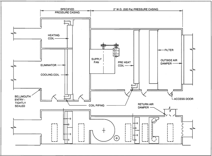
FIG. 6-4 OVER 2" W.G. CASING ARRANGEMENT
6.8
FIG. 6-5 OVER 2″ W.G. PRESSURE APPARATUS CASING
6.9
FIG. 6-5M OVER 500 Pa PRESSURE APPARATUS CASING
6.10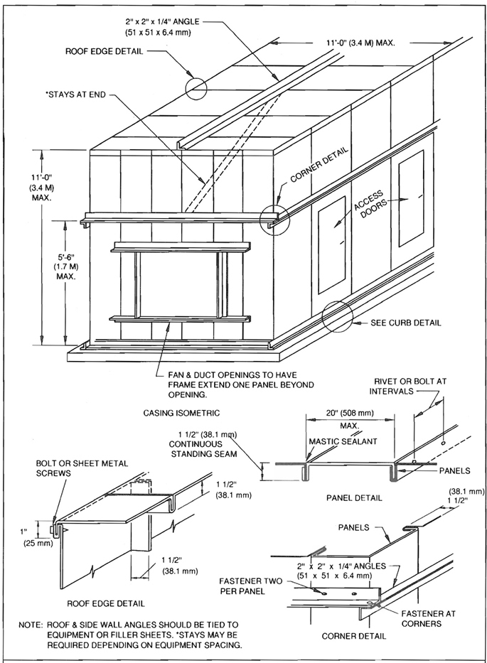
FIG. 6-6 INSIDE SEAM CASING - 6″ W.G. (1500 Pa) MAX.
6.11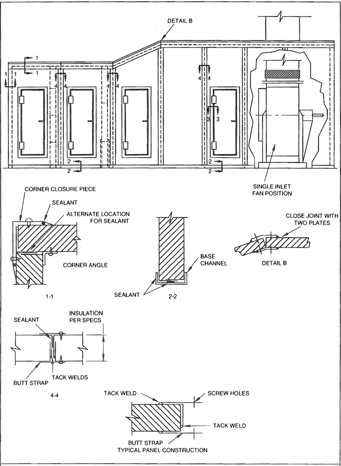
FIG. 6-7 DOUBLE WALL CASING
6.12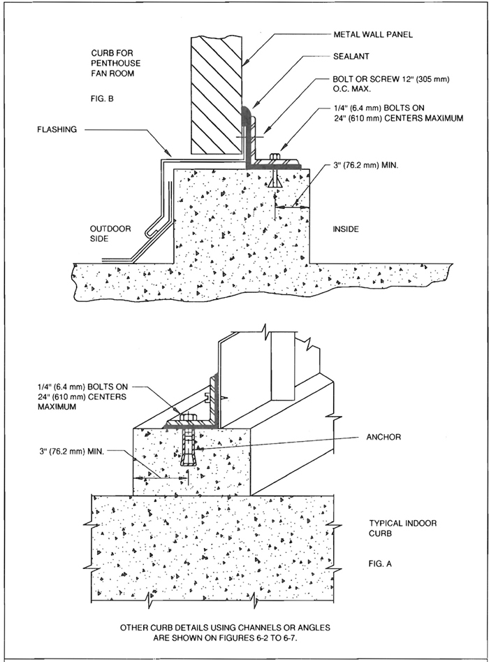
FIG. 6-8 CURB DETAIL
6.13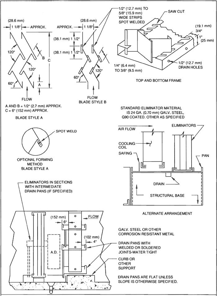
FIG. 6-9 ELIMINATORS AND DRAIN PANS
6.14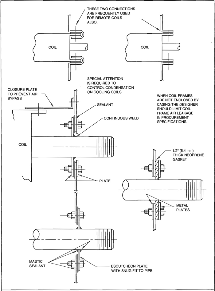
FIG. 6-10 PIPE PENETRATIONS OF CASINGS
6.15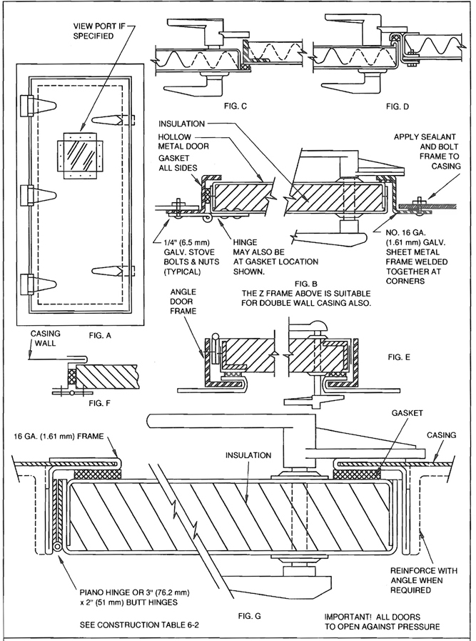
FIG. 6-11 CASING ACCESS DOORS - 2″ W.G. (500 Pa)
6.16| Gage | ||||||
|---|---|---|---|---|---|---|
| Door Size | No. Hinges * | No. Handles | Door | Back | Frame | Insulation (If req’d) |
| 72″ × 18″ up | 4 | 3 | 20 | 22 | 1 1/2″ × 1 1/2″ × 1/8″ | 1″ |
| 57″ × 18″ up | 3 | 2 | 22 | 24 | 16 ga. | 1″ |
| 45″ × 18″ up | 3 | 2 | 22 | 24 | 16 ga. | 1″ |
| 36″ × 18″ up | 3 | 2 | 22 | 24 | 16 ga. | 1″ |
See Fig. 2-12 for other construction details that may be suitable for small doors.
*Continuous piano hinge is optional.
| GAGE (mm) | ||||||
|---|---|---|---|---|---|---|
| Door size (mm) |
No. Hinges * |
No. Handles | Door | Back | Frame | Insulation (If req’d) (mm) |
| 1800 × 450 | 4 | 3 | 1.00 | 0.85 | 38.1 × 3.2 | 25.4 |
| 1450 × 450 | 3 | 2 | 0.85 | 0.70 | 1.61 | 25.4 |
| 1150 × 450 | 3 | 2 | 0.85 | 0.70 | 1.61 | 25.4 |
| 900 × 450 | 3 | 2 | 0.85 | 07.0 | 1.61 | 25.4 |
See Fig. 2-12 for other construction details that may be suitable for small doors.
*Continuous piano hinge is optional.
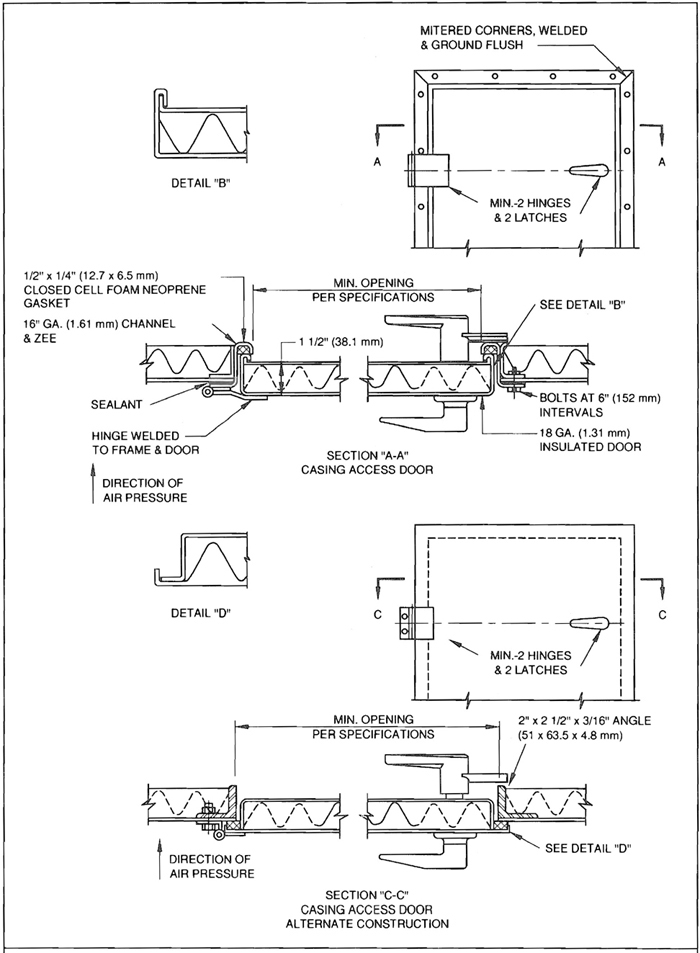
FIG. 6-12 CASING ACCESS DOORS - 3-10″ W.G. (750-2500 Pa)
6.18Casings should be built in a rectangular box shape. Tapered sides and roofs should be avoided primarily because of the difficulty in developing adequate strength and air tightness at the joints. In theory, the tapered casings conserve energy and facilitate uniform air distribution. However, as a practical matter, the tapers required for ideal expansion or contraction are such that there is seldom enough space to accommodate them in typical equipment rooms.
Several alternative constructions are illustrated. The contractor is obligated to select and use these construction details or their equivalent to satisfy the pressure level designated by the designer.
Therefore, all details such as bracing, curb connections, roof and sidewall connections, access doors, etc., must be carefully constructed to carry their share of the load.
CASING ASSEMBLY DETAILS SHOWN ARE NOT THE ONLY SATISFACTORY METHODS. OTHER TECHNIQUES ARE EQUIVALENT OR SUPERIOR. AUTHORITIES SHOULD JUDGE ALTERNATIVES ON THE BASIS OF ACCEPTABLE EVIDENCE.
Single wall casings may be constructed from continuous standing seam reinforced panels or one of the alternative constructions. The same gage of metal is used on all sides. Galvanized steel is standard sheet material. Black iron stiffeners are standard.
Double-wall, factory- or shop-insulated casings are fabricated in a variety of types and thicknesses by specialized producers. Some offer acoustical control through a perforated inner liner.
There are so many possible variations of the double-wall casing construction that it is impractical to detail them in this manual. If a contractor wants to fabricate this type of casing, it is suggested that strength of the panels be determined by structural calculations or pressure tests on mock-ups. Particular attention should be given to the design of airtight joints for panels with perforated liners.
A cubic foot (28.32 L) of water weighs approximately 62.4 lbs. (28.3 Kg). A one- inch (25 mm)- high column of water exerts a pressure of 1/1728 of 62.4 (28.3 Kg) or .361 lbs. (1.64 Kg) on one square inch (645 mm2). On one square foot (0.0929 m2) the load is 1/12 of 62.4 (28.3 Kg) or 5.2 lbs. (2.36 Kg). The following table relates static pressure to pounds per square foot:
| Static Pressure | ||
|---|---|---|
| (in.) | (Pa) | psf |
| 1″ water gage | (250) | 5.2 |
| 2″ water gage | (500) | 10.4 |
| 3″ water gage | (750) | 15.6 |
| 4″ water gage | (1000) | 20.8 |
| 6″ water gage | (1500) | 31.2 |
| 8″ water gage | (2000) | 41.6 |
| 10″ water gage | (2500) | 52.0 |
| 1″ water gage is 0.036 psi (0.25 KPa). | ||
| 1 psi is 27.69″ w.g. (6,9234 Pa) | ||
Casings are normally set on a 4 to 6 inch high (102 to 152 mm) concrete curb to facilitate housekeeping and also to contain any water which may leak from the coils or eliminators. The concrete curbs are normally poured on top of the finished floor. In order to prevent the forces on the casing walls from shearing off the curb, the curb should be securely doweled to the floor. If the floor is waterproofed, the curb should be doweled through the waterproof membrane into the structural slab.
Unless required to permit replacement of larger equipment such as a fan motor, duct access door size should be limited to approximately 20 inches (508 mm) wide by 54 inches (1372 mm) high. This is an adequate size for personnel and most equipment. Larger doors should be avoided since they break the continuity of the wall reinforcing. DOORS SHOULD OPEN AGAINST THE AIR PRESSURE. This arrangement utilizes the air pressure rather than the door latches to force the door against the sealing gasket.
All joints, seams, and connections should be sealed. Sealing is equally important on suction and discharge sides of the fan. Gasketing may suffice for some assemblies.
Leakage testing of casing is not routinely practical. Attention to workmanship and inspection of the pressurized installation will normally suffice for airtightness.
6.19Drainage facilities must be provided in the coil and eliminator sections of the casing to handle condensation on the cooling coil.
Conventional drains without deep seal traps will not give satisfactory performance. Drainage may be directly into the sewer system through a floor drain in the casing, or indirectly through the casing curb to an exterior floor drain. In either case, THE DRAIN LINE MUST BE PROVIDED WITH A WATER SEAL AT LEAST 2 INCHES (51 mm) GREATER THAN THE MAXIMUM STATIC PRESSURE IN THE CASING.
If space is available, water and steam coil connections should be manifolded inside the casing to minimize the number of penetrations through the casing walls. Piping penetrations must be carefully sealed, especially on chilled water piping because any leakage will force condensation along the pipe insulation.
The casing up to the suction side of the fan is normally constructed as a conventional low-pressure casing.
If the fan and the return and fresh air damper controls are not properly synchronized, it is possible that the high velocity supply fans will exert an extreme negative static pressure on the low pressure casings. It is not necessary to build these casings to withstand these unusual pressures. However, the fan and damper controls must be carefully coordinated so that it is impossible for such a negative pressure condition to occur. Safety relief panels or dampers may be designed into the system to prevent damage.
CONTRACTORS SHOULD BE PARTICULARLY AWARE OF THE POTENTIAL DAMAGE WHICH CAN BE CAUSED BY IMPROPER MANIPULATION OF THE DAMPER CONTROLS DURING CONSTRUCTION AND INITIAL START-UP.
THE OUTSIDE AIR OR RETURN AIR DAMPER SHOULD BE BLOCKED OPEN UNTIL THE AUTOMATIC CONTROL SYSTEM IS PUT INTO OPERATION AND PROPERLY ADJUSTED.
6.20SMACNA has conducted testing and analysis of galvanized steel ducts of gages up to 96" in size, between 28 (0.48 mm) and 16 (1.61 mm) in size, inclusive, at static pressure levels ranging from 0.1" w.g. (25 Pa) to 10" w.g. (2500 Pa). Tests were conducted in both positive and negative pressure modes. The study recorded pressure, deflection, and other duct element behavior. It concluded that the structural behavior of duct is reasonably predictable in terms of pressure, deflection, metal thickness, and stiffener spacing. Committees conclude that the functional criteria previously used are valid with some new provisions for tolerances. The general performance criteria for ducts is reviewed on page 1-3 and outlined in 7.3.1.
The criteria used by SMACNA in its test program and in development of new duct tables is as follows.
1. Sheet
The sheet must resist both deflection caused by internal pressure and vibration due to turbulent air flow. Because space is a limiting factor, and there is a need to maintain an approximately rectangular cross section, sheet deflections for ducts were limited as listed in Figure 7-1.
The current test program did not include vibration analysis. A discussion of vibration parameters follows in this chapter. Commentary also appears with Table 1-1 and in the notes for Tables 1-3 to 1-13. It was concluded that the limited risk of an occasional problem is preferable to postponing use of multiple sheet gages until the boundaries of stability can be completely defined.
Crossbreaking or beading of unbraced duct sides larger than certain dimensions is effective in dealing with commercial tolerances on out-of-flatness, natural sag from dead weight, and with the flexure reversals that may result when duct pressure is inadequate to stretch the sheet taut. If pressure does not produce a taut sheet, vibration may result. Beading is considered as effective as crossbreaking, but formation of a suitable bead requires adjustment for each sheet thickness. Criteria for crossbreaking or beading is given in Figure 1-8. NEITHER IS A SUBSTITUTE FOR REINFORCEMENT.
The provisions for flexure control do not eliminate rumble during start-up and shutdown. Lagging or other measures must be designed if rumble is to be eliminated.
2. Reinforcing
The reinforcing members must restrain the deflection of the sheet and must resist their own deflection. They must also handle bending moments so that allowable stresses are not exceeded.
3. Seams
Longitudinal seams must be able to withstand 1.5 times the maximum operating pressure without deformation or failure.
4. Joints
Transverse joints must be able to withstand 1.5 times the maximum operating pressure without failure. Where a transverse joint acts as a reinforcing member, it must not deflect excessively nor incur excessive stress.
5. Beam Strength of Duct Section
A duct section between adjacent hangers must be able to carry its own weight and to resist external loads for which it is constructed. The joints and sheets listed in the current construction tables are not specifically designed to support the weight of a person. The support systems are not qualified for supplemental loads either.
6. Leakage
See Table 1-2 and the discussion of leakage in relation to pressure level. Ducts are not absolutely airtight and designers should not impose unreasonably low limits of leakage. Careful selection of closure methods can ensure adequate performance. However, designers must consider that even slight leakage may cause bulges in an airtight, flexible skin that encloses a positive pressure duct.
Leakage is primarily a function of the static pressure differential. It is independent of joint orientation and of velocity levels of 2000 fpm (11.6 mps) and less. Rectangular longitudinal seam leakage for Pittsburgh and snaplock seams is low compared to that in transverse joints.
Because the tables are derived from test data averages, construction conforming to Tables 1-3 to 1-9 will not always limit deflections of sheets and stiffeners to the stated levels. Also, crossbreaks establish an initial deflection which, when added to that generated by pressure, may result in sheet deflections slightly more than the limits discussed.
7.1Furthermore, the ability of a reinforcing member to perform its function is critically affected by the location and adequacy of its attachment to the duct. These variables change with the negative pressure and positive pressure modes.
A duct system is an assembly whose primary function is to convey air between specified points. In fulfilling this function, the duct assembly must perform satisfactorily with regard to certain fundamental performance characteristics. Elements of the assembly are sheets (duct envelope), reinforcement, seams, and joints. With regard to the duct assembly and its elements, theoretical and/or practical limits must be established for:
In establishing limitations for these factors, consideration must be given to the effects of the pressure differential across the duct wall, airflow friction losses, air velocities, infiltration or exfiltration, as well as the inherent strength characteristics of the duct components. Construction methods that economically achieve the predicted and desired performance must be determined.
Selected specific performance requirements for rectangular, round and flat-oval ducts are codified in SMACNA Duct Performance Test Standard No. DPTS-1995.
7.2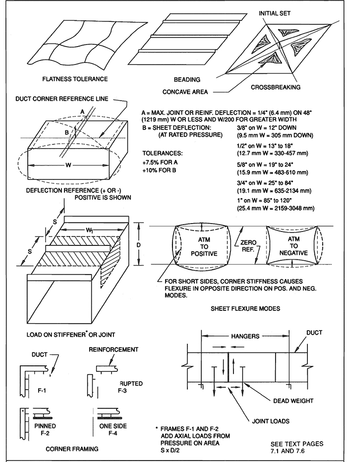
FIG. 7-1 MODELS FOR FUNCTIONAL STANDARDS
7.3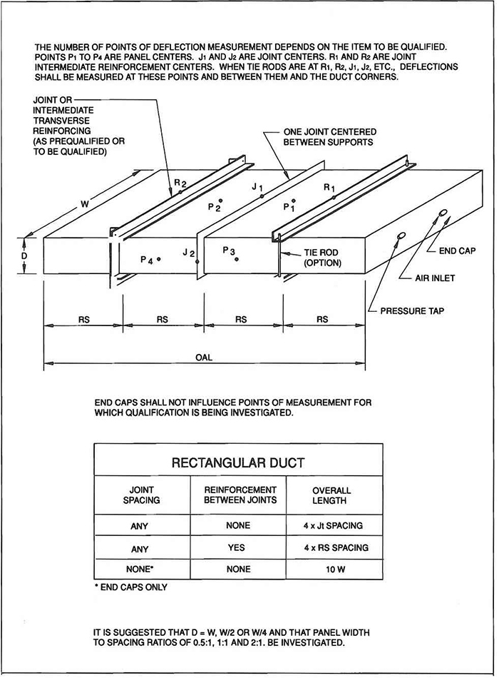
FIG. 7-2 TEST DUCT CONFIGURATION
7.4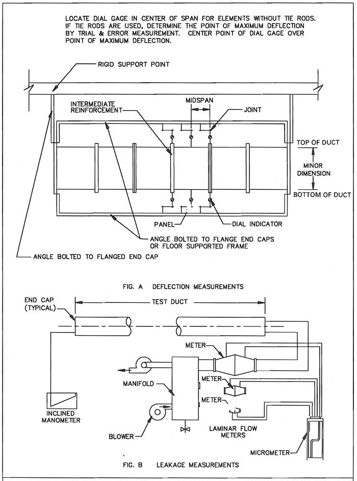
FIG. 7-3 DEFLECTION AND LEAKAGE MEASUREMENT
7.5SMACNA
DUCT PERFORMANCE TEST STANDARD
NO. DPTS-1995
1.0 PURPOSE
1.1 The purpose of this standard is to provide a uniform reliable laboratory test procedure for evaluating various performance attributes of HVAC air ducts.
2.0 Scope
2.1 The scope of this standard covers test methods and evaluation criteria for the following:
3.0 Performance Requirements
3.1 Burst and Collapse Tests
These shall determine that a minimum safety factor of 2 on round and oval duct and 1.5 on rectangular duct exists for the desired duct construction pressure classifications.
3.2 Rectangular Duct Deflection Limits
| Duct Wall | Limit |
|---|---|
| W = 12" (305 mm) or less | 3/8" (9.5 mm) |
| W = 13" (330 mm) to 18" (457 mm) | 1/2" (12.7 mm) |
| W = 19" (483 mm) to 24" (610 mm) | 5/8" (15.9 mm) |
| W = 25" (635 mm) to 84" (2134 mm) | 3/4" (19.1 mm) |
| W = 85" (2159 mm) to 120" (3048 mm) | 1" (25.4 mm) |
| Tolerance of +10% |
| Joints and Reinforcements | Limit |
|---|---|
| W = 48" (1219 mm) or less | 1/4" (6.35 mm) |
| W = 49" (1245 mm) to 120" (3048 mm) | W/200 |
| Tolerance of +7.5% |
3.3 Oval Duct Deflection Limits
| Duct Wall | Limit |
|---|---|
| At rated pressure | 3/4" (19.1 mm) |
| At atmospheric pressure | 1/4" (6.35 mm) |
| Major dimension W = 36" (914 mm) or less | |
| W over 36" (914 mm) | 1/2" (12.7 mm) |
| Tolerance of +7.5% |
3.4 Round Duct Deflection Limits
| Duct Wall | Limit |
|---|---|
| Positive Pressure | Not applicable if shape is round at read pressure |
| Negative Pressure | D/200 |
3.5 Leakage Evaluation
Only applicable for the determination of a leakage class within the SMACNA HVAC Air Duct Leakage Test Manual for experimental purposes.
3.6 Suspension Effects (Optional)
Suspension
Using supports at the maximum specified interval a weight equal to the dead weight of the duct is suspended at midpoint between hangers (over a joint if a joint could occur in the span and also on an unjointed span if the joint spacing could equal or exceed the hanger span). Leakage and sag (referenced to support points) are measured before and at the end of one hour. Report Leakage Classes as in Leakage Evaluation.
4.0 Test Setup
4.1 See Figures 7-1, 7-2, and 7-3, the instrumentation requirements and the data to be recorded and reported. Ducts shall be assembled in accordance with the test sponsor’s instructions.
4.2 The support frame for dial indicators may not rest on ducts except at end caps.
4.3 On rectangular and oval ducts, the test sponsor may have only top measurements for (+) pressure qualification and only bottom measurements for (−) pressure service. The greater duct dimension must be on the top, not on the side. The setup must provide for recording for both the top and bottom sides of rectangular and oval duct concave or convex sag for the theoretical flat spans. A rigid straight cross-member or other appropriate means of determining zero pressure deflections for the flat spans must be provided.
4.4 Test set ups for round and oval ducts are not required
7.6to evaluate circular or semi-circular portions of flanges or angle reinforcements.
4.5 Test setups for round duct wall deflections require placement of displacement indicators at 12, 3, 6, and 9 o’clock around the perimeter.
5.0 INSTRUMENTATION
5.1 Accuracy and Precision. For the purposes of this standard, requirements for accuracy and precision, or for maximum error, are specified. The systematic error in an instrument can be minimized by suitable calibration procedures. Random error in an instrument can to some extent be reduced by careful technique in reading and by choosing scale divisions so as to assist in estimating values.
5.2 Temperature Measurement. Wet- and dry-bulb thermometers, transducers, or sensors shall have an accuracy of ±1°C and a precision of ±0.5°C or better. Calibration thermometers, transducers, and sensors shall be calibrated over the range of temperatures expected to be encountered during a test, using a reference thermometer having a calibration that can be traceable to the National Institute of Standards and Technology (NIST), or another national laboratory recognized by NIST.
5.3 Pressure Measurement. Duct pressure shall be measured with a manometer or other instrument with an accuracy of ±1% or less and the precision shall be ±0.5% or less. Manometer readings must be corrected for variation of specific weight of gage fluid with temperature, any difference in gas column balancing effect from standard, change in length of the graduated scale due to temperature, or capillary effects.
5.4 Dial Indicators. Displacement indicators shall have a suitable range, 0.001" or 0.01 mm maximum graduations and an accuracy of 1%.
5.5. Laminar Flow Meter. Laminar flow elements shall have a 1% precision, and be calibrated to within ±0.5% of flow standards traceable to NIST. A micromanometer shall be used to measure the pressure drop across the laminar flow element.
5.6 Piping. The Figure 7-3B manifold shall be 6" (150 mm) diameter pipe minimum. Piping between the manifold and a test duct end cap shall be 2" (50 mm) diameter minimum.
5.7 Prime Movers. The number and capacity of blowers shall maintain positive and negative test pressures. Blowers may be operated individually or in parallel at full or reduced speed using variable frequency or voltage control. A bleed valve may be installed in the fan discharge manifold to provide fine flow adjustment.
6.0 TEST SEQUENCE
Step 1. Set up the dial indicator(s) over the test point(s). Record the dial indicator reading (D1) at zero gage pressure. Determine the sag for top and bottom flat surfaces as required for section 4.3 even though the DAVE calculation might apply for only one surface.
Step 2. Pressurize the duct to the target classification. After pressure is stable for one minute, record the dial indicator reading (D2). Examine the duct.
Step 3. Relieve pressure and record the dial indicator reading (D3).
Step 4. Pressurize rectangular duct 50% above the step 2 level for a minimum of five minutes. Pressurize round and oval ducts 100% above the step 2 level for five minutes minimum. Examine the duct. A dial indicator record is optional.
Step 5. Relieve the pressure. Examine the duct. Record the dial indicator reading (D4).
Calculate the average deflection DAVE.
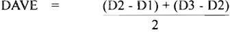
Where:
| D1 | = | Dial indicator reading per step 1 |
| D2 | = | Dial indicator reading per step 2. |
| D3 | = | Dial indicator reading per step 3. |
This relates to the performance requirements in Section 3 of this test standard. The DAVE calculation does not require that the performance limits for Section 3.2 and 3.3 apply to theoretical flat zero reference datum.
7.0 DATA TO BE INCLUDED IN REPORTS OF TESTS
The laboratory may just report its findings or may certify that compliance with a particular standard or requirement has been met.
7.8Method 1
Show by written analysis and commentary that any features that are different from the reinforcement and assembly scheme will result in:
Method 2
Present substantial evidence of historical acceptability for the use intended, and show that the previous use has been subjected to the pressures, velocity levels, and other conditions for which rating is desired.
Method 3
Construct, test, and rate specimens of the contemplated design.
Method 3A
Test only the component being substituted or test the component plus any connected components in a manner that will simulate the actual loading and will correlate with actual performance. Show that this approach will not impair or reduce the performance of the entire assembly.
Method 3B
Test a full specimen. Construct a specimen using the desired scheme of sheet thickness, joint type, intermediate stiffener, sealant, fasteners, etc. Conduct tests in the positive or negative mode of pressurization, as desired. Use instrumentation and follow procedures that will produce laboratory accuracy. Record the proceedings and observations. Write conclusions showing equivalence to the construction tables published by SMACNA. Include a diagram of the specimen tested.
NOTICE: Test procedures 3A and 3B may result in showing compliance with the performance criteria published by SMACNA, and not result in structural failure in the specimen. It is also desirable (but not required) to know the conditions under which failure occurs. If feasible, increase the pressure on the specimen until buckling, permanent deformation, or separation of parts occurs. This will indicate the safety factor of the construction and show the nature of the failure.
Structural Inadequacies
Joint separation
Seam separation
Permanent warp, buckling, or collapse
Excessive sag or misalignment at zero pressure
Excessive deflection in duct wall, reinforcements, or joints under pressure
Component or fastener breaking, pullout, or slip
Changing alignment or fit-up of components causing loss of seal effectiveness
Stress cracking
Susceptibility to damage from routine handling and from impact at assembly and installation
Inadequate Integration with Support Systems
Insufficient support causing misalignment of duct sections
Support detaching from duct assembly (if attached)
Support deflecting under load, adversely affecting duct integrity or shape retention
Support contact with duct being periodic and causing noise
Note: Where riser or horizontal duct supports transmit loads to joints or reinforcements, these loads can affect the integrity of the duct system.
Sponsors of new or proprietary transverse joining systems are encouraged to have their tests witnessed and certified by a disinterested responsible party such as a commercial testing laboratory. Recommended construction tables and details should follow a format similar to that used in this manual if an indication of equivalency is intended. Evidence of equivalency should include information on the E1 rigidity classification calculation. SMACNA does not endorse or approve proprietary constructions and does not validate their analysis or tests as being equivalent to SMACNA classifications. Authorities are invited to evaluate such constructions based on evidence presented by their sponsors.
7.10The following discussion reviews vibration research conducted by SMACNA and reported in the May 1984 issue of the ASHRAE Journal. It is extracted and used by permission of the American Society of Heating, Refrigerating & Air Conditioning Engineers, Inc. No inference that ASHRAE agrees with these opinions is intended. For a more recent discussion of acoustical analysis of ducts see the “Sound and Vibration” Chapter in the ASHRAE Systems Handbook and Section XI in SMACNA’s HVAC Duct Systems Design manual.
IMPORTANT NOTICE! The rectangular duct reinforcement tables in these standards and in former editions do not eliminate rumble on system start-up and shutdown. Lagging, diagonal bracing, or other acoustical treatment will be necessary to reduce or eliminate rumble.
The object of the test was to determine the behavior of a variety of rectangular duct constructions for various air velocities and static pressures. Behavior was measured in terms of deflection and vibration amplitude.
The test apparatus is illustrated in Fig. 7-4. Air from the fan passed through a calibrated orifice and a square-throat elbow into the test specimen. Then it discharged into a plenum with an outlet damper. Air pressure and flow were controlled by the fan inlet damper and the outlet damper at the end of the system. A manually operated bypass damper was used whenever the desired airflow through the specimen was below the normal operating range of the fan. Four sizes of orifices were used for different flow ranges. The square-throat elbow with turning vanes was installed upstream of the test specimen in order to create a turbulent airflow like that found in actual installations. The pressure in the test specimen was sensed by a static pressure probe installed in each of the test specimens. The displacement of the sheet was measured by a calibrated linear potentiometer. The movable arm of the potentiometer was secured to the sheet by a permanent magnet, and the housing of the potentiometer was secured to an aluminum channel superstructure, which was in turn supported by the corners of the duct. Thus the sheet displacement was measured relative to the duct itself. This arrangement prevented false readings caused by movement of the testing system relative to the building structure.
The static pressure and differential orifice pressure were measured by electronic pressure transducers, which in turn were calibrated and monitored by liquid manometers. The static pressure, differential orifice pressure, and sheet displacement were simultaneously recorded on an oscillograph chart. The deflection of the reinforcing angles was measured with a dial indicator using as a reference the same superstructure used for the potentiometers, and these measurements were recorded manually.
Most of the tested ducts had a uniform depth of 8" (203 mm). Because the top, bottom, and sides of a rectangular duct act as independent load bearing panels, there was no reason to make a separate study of each of these panels, or to study the effects of combining various sizes of top and side panels.
Duct widths tested were 10 (254), 12 (305), 18 (457), 24 (610), 36 (914), 48 (1219), 54 (1372), 60 (1524), 72 (1829), and 84 inches (2134 mm). Ducts wider than 84 in. (2134 mm) could not be tested due to limited capacity of the supply fan to provide sufficient velocities at the higher test pressures.
Duct specimens were 8 (2.44) to 12 feet (3.66 m) long, usually with 2 (0.61) to 4 feet (1.22 m) connecting pieces on each end. Longitudinal seams were button punch snap lock for 24 (0.70) through 20 gage (1.00 mm) sheets. Lock seams were used for 18 gage (1.31) ducts. 16 (1.61) and 14 gage (1.99 mm) ducts had welded seams. Reinforcing angles were secured with sheet metal screws and tie rods on each end. Transverse joints were flanged and edge-welded. Each specimen normally included two transverse joints.
For each width of duct, the sheet gage, reinforcing size, and reinforcing spacing were varied in order to determine the lowest cost construction that would perform within the standards.
Constant-pressure test runs were made on each duct specimen, varying the velocity continuously from about 6,500 (33) down to about 2,000 fpm (10 mps). The constant pressure runs were made at 10.0 (2500), 6.0 (1500), 2.0 (500), 1.5, (375) and 1.0 in. w.g. (250 Pa) static pressure as measured in the specimen.
7.11
FIG. 7-4 TEST APPARATUS
7.12
FIG. 7-4M TEST APPARATUS
7.13| Static Pressure in. W.G. (Pa) |
Average Velocity fpm |
(mps) |
|---|---|---|
| 1.5 (375) | 2500 | (12.7) |
| 2.0 (500) | 2750 | (14) |
| 4.0 (1000) | 3500 | (17.8) |
| 8.0 (2000) | 5500 | (27.9) |
| 10.0 (2500) | 6500 | (33) |
The oscillograph traces were examined to determine, for each pressure, the maximum sheet deflection and the maximum air velocity at which the amplitude of sheet vibration was equal to the arbitrary maximum value established as standard. With amplification available from the recording instruments, this value was the width of one line on the trace, which was equal to a movement of the sheet of .01785 in. (0.4534 mm) (slightly over 1/64"). This velocity is termed the “threshold velocity.”
It was not feasible to conduct the tests to establish the exact relationship between the threshold velocity and each of the variable of duct size, sheet gage, and reinforcing spacing. Instead it was decided to arbitrarily establish minimum threshold velocities for various static pressures. The intent was that the resulting criteria would cover all of the operating conditions in normal- to high-velocity air conditioning systems.
Because operating conditions are the designer’s choice, these criteria were established through a poll of consulting mechanical engineers. Based on their responses, Table A lists the minimum threshold velocities used in evaluating the test results.
In all cases the performance of the duct specimen followed the same pattern.
All of the above phenomena would seem to be readily predictable with the exception of the last two. Why would a light gage sheet resist vibration more than a heavy gage sheet, and why would a sheet vibrate more at lower pressures?
Careful observation of all specimens showed that the sheet acts more as a membrane than as a beam. A sheet acting as a beam would require a much greater section modulus, calling for thicknesses beyond those of sheets. However, a relatively heavy sheet, say 16 gage (1.61 mm), does retain some of the stiffness of a beam, while the lighter sheets, say 20 gage (1.00 mm), are quite limber.
The side of the duct is easy to move back and forth (vibrate) if it is not taut. A 16 gage (1.61 mm) sheet cannot be stretched taut by lower static pressures, say 2 (500) to 4 in. (1000 Pa), because of its inherent stiffness, whereas the lighter 20 gage (1.00 mm) sheet does become taut at these pressures.
Commercial sheets are not absolutely flat but instead have both concave and convex areas or “waves.” If a relatively heavy gage sheet is subjected to low-range operating pressures, some concave areas might be on the verge of “popping out” or snapping over center to conform to the overall convex shape of the sheet. If an area is near this equilibrium condition, then relatively small but rapid variations in static pressure caused by turbulence will make that area vibrate violently.
In addition to the random waves in commercial sheets, the sheet forming the top of the duct will sag and form a concave area between the reinforcing members. This is due to the dead weight of the sheet and occurs at zero or low internal static pressures. The top sheet will not be stretched taut until the internal static pressure is adequate to overcome both the dead weight of the sheet and the internal forces which cause the waves. Here again, the equilibrium static pressure for heavy gage sheets, can occur well within operating pressure ranges, while for light gage sheets, equilibrium will occur below operating pressure.
From the foregoing, it might appear that it would always be best to use a light gage sheet. However, as the duct
7.14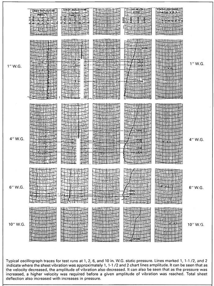
FIG. 7-5 OSCILLOGRAPH TRACES
7.15width increases, it is also necessary to increase sheet gage in order to meet the deflection criteria.
A natural approach for maintaining a sheet in a convex shape is to cross break it. Unfortunately, cross breaking results in concave areas between the break lines. The technique of cross breaking is successful in reducing vibration when applied to low velocity ducts because internal static pressures are seldom high enough to cause the concave areas to “pop out.” Also, low velocity ducts are not normally subjected to the turbulence found in high velocity ducts. Therefore, the forces causing vibration are much smaller.
The test results showed that the effect of cross breaking high velocity ducts is dependent on the sheet gage. Because they were stretched taut at low pressures, cross breaking had a minimum effect on light gage ducts. On the other hand, higher pressures were required to stretch taut the heavy gage sheets which had been cross broken than those not cross broken. It was observed that in general, cross breaking was not beneficial to high velocity duct performances.
Vibration of the sheet is undesirable:
Complete and definitive testing in these three problem areas was not practical under the financial and time limitations of this program. It was instead decided to rely on the judgment of experienced parties to determine the criteria for acceptability. Thirty ventilation contractors and design engineers witnessed various test runs and expressed their opinions on the effects of vibration when the sheets were made to vibrate at 1, 1-1/2 and 2 times the maximum standard (0.01785 in.) (0.4534 mm).
Fatigue failure in steel ducts is uncommon. The consultants had seen fatigue failure only in cases of much more severe vibration, usually where there were stress reversals such as that created by a poorly secured turning vane flapping in the airstream.
It is not good practice for the duct sheet to come in contact with other parts of a building. It was agreed that the maximum deflection and amplitude values set as standard were reasonable enough to prevent such contact. Where ducts are covered with insulation, vibration transmission by contact is further minimized.
As a practical matter, the foregoing two problems were not as great a concern as the possibility of excessive noise. Due to the high ambient noise caused by having the complete air handling system in one room, it was impossible to measure the amount of noise radiated by the duct specimen. Our consultants evaluated the test runs by visual observation, by touch, and by ear. On this basis, they unanimously agreed that the maximum amplitude of vibration established as a standard was well within the limits of vibration considered acceptable.
It was possible to take vibration readings of the various specimens and system components. Magnetic tape recordings were made of the vibration of duct walls as detected by an accelerometer pickup. A preamplifier was used that had uniform characteristics throughout the audio frequency range. After the test runs, the consultants listened to the recordings in a quiet room and judged them. Certain qualitative judgments were made concerning these listening tests. Additional measurements were made concerning the relative noise intensity as a function of sheet gage and static pressure.
The levels in Table B indicate the relative vibration under the various conditions of test on a logarithmic scale as used for sounds. The absolute values are of no importance, but the relative values are similar to those obtained if it had been possible to measure noise directly on a decibel scale; that is, for an increase of 3, the ratio of vibration is doubled.
For an increase in 10, the vibration intensity is increased tenfold. The basis of interpretation of the readings of relative vibration is the assumption that the intensity of radiated sound will vary with the intensity of vibration. In actuality, the relationship between surface vibration and sound radiation is also a function of frequency. In our tests, the differences in relative vibration however are significant enough to assume that an increase in radiated sound will result from an increase in vibration of the sheet. The significance of the tests was the determination of trends rather than the measurement of levels.
7.16In assessing the differences between the various conditions, it should be realized that the isolation between the various portions of the duct are minimal, especially for the case where a heavy gage and a light gage duct are connected in series in the test rig. Furthermore, with the existing test setup, vibration is easily conducted along the entire system with little reduction in amplitude. The differences that are noted therefore are minimum and it can be expected that considerable more differences would have occurred under ideal test conditions.
Vibration readings on a 42 × 8 in. (1067 × 203 mm) duct specimen, constructed of a 10 feet (3.05 m) long, 22 gage (0.85 mm) section, joined directly to a 10 feet (3.05 m) long, 16 gage (1.61 mm) section, are tabulated in Table B, Run No. 5.
| Run No. 5 -42 in. Wide Ducts | |||
|---|---|---|---|
| Static Pressure in W.G. (Pa) |
Velocity fpm (mps) |
Relative 22 ga (0.85 mm) Duct |
Vibration 16 ga (1.61 mm) Duct |
| 10.1 (2500) |
5,680 (28.9) |
30 | 32 |
| 8.1 (2000) |
6,560 (33.3) |
31 | 33 |
| 6.1 (1500 |
6,560 (33.3) |
30 | 32 |
| 4.1 (1000) |
6,660 (33.8) |
30 | 33 |
| 2.5 (625) |
6,440 (32.7) |
32 | 42 |
Under these test conditions, the vibration intensity of the thinner duct was consistently lower in level than the heavier duct and showed a maximum difference at the lower pressures, for which visible motion of the duct walls was apparent in the heavier gages.
RUN NO. 6 (Continued) 42 in. (1067 mm) Wide Duct 6,270 fpm (31.6 mps) Velocity, 6.0 inches (1500 Pa) static pressure
| Position | Relative Vibration |
|---|---|
| Outlet plenum box | 32 |
| 16 ga. (1.61 mm) duct section | 32 |
| 22 ga. (0.85 mm) ducts section | 29 |
| Floor next to duct specimens | 11 |
| Inlet plenum upstream of duct specimens | 37 |
| Top of elbow | 39 |
| Top of round to rectangular transition | 38 |
| Round duct on outlet side of orifice | 35 |
| Round duct on inlet side of orifice | 39 |
| Round duct on outlet of fan under bleed-off | 38 |
A most interesting set of measurements was obtained in Run No. 6 during which recordings were made at 10 different locations throughout the entire system. The lowest vibration in the system was obtained in the section of duct having the thinnest gage. The readings are not indicative of noise reduction because the frequency characteristic of the noise also changes. The thinner duct appears to sound significantly less loud than the heavier duct. This is in part due to less intensity, but also to the lower pitch or frequency of the sounds.
Our study of noise radiation was conducted under less than ideal conditions. However, its results appear to substantiate the assumption that light gages in high velocity duct will not result in greater noise radiation than heavy gages.
7.17 7.18| A-2 | Galvanized Sheet Thickness |
| A-3 | Manufactures Standard Gage-Thickness-Uncoated Steel Sheet |
| A-4 | Stainless Steel Sheet Thickness |
| A-5 | Aluminum Sheet Thickness |
| A-6 | Metric Conversion Chart |
| A-7 | Duct Surface Area |
| A-8 | Galvanized Sheet Weight Comparison |
| A-10 | Approximate Weight-Round Steel Duct |
| A-11 | Areas and Circumferences of Circles |
| A-12 | Angle, Bar and Channel Properties |
| A-13 | 2" w.g. Narrowscope Table 1-5 E4 |
| A-14 | 2" w.g. Narrowscope Table 1-5 E5 |
| A-15 | 1" w.g. Narrowscope Table 1-4 E4 |
| A-16 | 1" w.g. Narrowscope Table 1-4 E5 |
| A-17 | 26, 24, 22 Gage Composite of Tables 1-3, 1-4 and 1-5 |
| A-18 | 20, 18, 16 Gage Composite of Tables 1-3, 1-4 and 1-5 |
| A-19 | Contractor Analysis of Shop Standards |
| A-20 | Sample Shop Standards |
| A-21 | Blank Form for Shop Standards |
| A-22 | Dependent Variables |
| A-23 | 26 Gage Duct Pressure Comparison |
| A-24 | 24 Gage Duct Pressure Comparison |
| A-25 | 22 Gage Duct Pressure Comparison |
| A-26 | 20 Gage Duct Pressure Comparison |
| A-27 | 18 Gage Duct Pressure Comparison |
| A-28 | 16 Gage Duct Pressure Comparison |
| A-29 | Single Path Air Systems |
| A-30 | Dual Path Air Systems |
| A-31 | Terminology for Central Station Apparatus |
| A-32 | Typical HVAC Unit Connections |
| A-33 | Motor Arrangements Centrifugal Fans |
| A-34 | Fan Rotation and Discharge Position |
| A-35 | Typical Belt Guards |
| A-36 | Typical Isolation Devices |
| A-37 | Radiation Protection at Wall Openings for Duct or Pipe |
| A-41 | Number of Short Radius Vanes |
| A-42 | Number of Short Radius Vanes (Metric) |
| A-43 | Construction of Short Radius Vanes |
| A-44 | Contributers to Previous Documents |
| Gage | Thickness in Inches | Weight | Thickness in Millimeters | |||||||
|---|---|---|---|---|---|---|---|---|---|---|
| Min. | Max. | Nom. | Min. lb/sf |
Nom. lb/sf |
Max. lb/sf |
Nom. kg/m2 |
Min. | Max. | Nom. | |
| 33 | .0060 | .0120 | .0090 | .2409 | .376 | .486 | .1524 | .3048 | .2286 | |
| 32 | .0104 | .0164 | .0134 | .4204 | .563 | .665 | .2642 | .4166 | .3404 | |
| 31 | .0112 | .0172 | .0142 | .4531 | .594 | .698 | .2845 | .4369 | .3607 | |
| 30 | .0127 | .0187 | .0157 | .5143 | .656 | .759 | 3.20 | .3188 | .4783 | .3988 |
| 29 | .0142 | .020 | .0172 | .5755 | .719 | .820 | .3569 | .5169 | .4369 | |
| 28 | .0157 | .0217 | .0187 | .6367 | .781 | .881 | 3.81 | .3950 | .5550 | .4750 |
| 27 | .0172 | .0232 | .0202 | .6979 | .844 | .943 | .4331 | .5931 | .5131 | |
| 26 | .0187 | .0247 | .0217 | .7591 | .906 | 1.004 | 4.42 | .4712 | .6312 | .5512 |
| 25 | .0217 | .0287 | .0247 | .8407 | 1.167 | .5274 | .7274 | .6274 | ||
| 24 | .0236 | .0316 | .0276 | .9590 | 1.156 | 1.285 | 5.64 | .6010 | .8010 | .7010 |
| 23 | .0266 | .0346 | .0306 | 1.0814 | 1.408 | .6772 | 8772 | .7772 | ||
| 22 | .0296 | .0376 | .0336 | 1.2038 | 1.406 | 1.530 | 6.86 | .7534 | .9534 | .8534 |
| 21 | .0326 | .0406 | .0366 | 1.3263 | 1.653 | .8296 | 1.0296 | .9296 | ||
| 20 | .0356 | .0436 | .0396 | 1.4486 | 1.656 | 1.775 | 8.08 | .906 | 1.106 | 1.006 |
| 19 | .0406 | .0506 | .0456 | 1.6526 | 2.061 | 1.028 | 1.288 | 1.158 | ||
| 18 | .0466 | .0566 | .0516 | 1.8974 | 2.156 | 2.305 | 10.52 | 1.181 | 1.441 | 1.311 |
| 17 | .0525 | .0625 | .0575 | 2.1381 | 2.546 | 1.331 | 1.591 | 1.461 | ||
| 16 | .0575 | .0695 | .0635 | 2.342 | 2.656 | 2.832 | 12.96 | 1.463 | 1.763 | 1.613 |
| 15 | .0650 | .0770 | .0710 | 2.6481 | 3.138 | 1.653 | 1.953 | 1.803 | ||
| 14 | .0705 | .0865 | .0785 | 2.8725 | 3.281 | 3.525 | 16.01 | 1.784 | 2.204 | 1.994 |
| 13 | .0854 | .1014 | .0934 | 3.4804 | 4.133 | 2.162 | 2.5823 | 2.372 | ||
| 12 | .0994 | .1174 | .1084 | 4.0516 | 4.531 | 4.786 | 22.11 | 2.523 | 2.983 | 2.753 |
| 11 | .1143 | .1323 | .1233 | 4.6505 | 5.394 | 2.902 | 3.362 | 3.132 | ||
| 10 | .1292 | .1472 | .1382 | 5.2675 | 5.781 | 6.002 | 28.21 | 3.280 | 3.740 | 3.510 |
| 9 | .1442 | .1622 | .1532 | 5.8795 | 6.614 | 3.661 | 4.121 | 3.891 | ||
| 8 | .1591 | .1771 | .1681 | 6.4874 | 6.875 | 7.222 | 4.040 | 4.500 | 4.270 | |
NOTES:
| M.S. Gage |
Weight lb/sf (kg/m2) |
Thickness | ANSI STANDARD B32.3 Preferred in Thickness Millimeters |
|||||
|---|---|---|---|---|---|---|---|---|
| Nominal | Hot Rolled | Cold Rolled | ||||||
| Min. | Max. | Min. | Max. | First | Second | |||
| 28 | .625 (3.051) |
.0149 in .378 mm |
.0129 in .328 mm |
.0169 in .429 mm |
.30 | |||
| 26 | .750 (3.661) |
.0179 in .455 mm |
.0159 in .404 mm |
.0199 in .505 mm |
.40 | .35 .45 |
||
| 24 | 1.000 (4.882) |
.0239 in .607 mm |
.0209 in .531 mm |
.0269 in .683 mm |
.50 | |||
| 22 | 1.250 (6.102) |
.0299 in .759 mm |
.0269 in .683 mm |
.0329 in .836 mm |
.60 | .65 .70 |
||
| 20 | 1.500 (7.232) |
.0359 in .912 mm |
.0329 in .836 mm |
.0389 in .988 mm |
.80 | .90 | ||
| 18 | 2.000 (9.764) |
.0478 in 1.214 mm |
.0428 in 1.087 mm |
.0528 in 1.341 mm |
.0438 in 1.113 mm |
.0518 in 1.316 mm |
1.00 1.2 |
1.10 1.40 |
| 16 | 2.500 (12.205) |
.0598 in 1.519 mm |
.0538 in 1.367 mm |
.0658 in 1.671 mm |
.0548 in 1.392 mm |
.0548 in 1.649 mm |
1.6 | 1.80 |
| 14 | 3.125 (15.256) |
.0747 in 1.897 mm |
.0677 in 1.720 mm |
0.817 in 2.075 mm |
.0697 in 1.770 mm |
.0797 in 2.024 mm |
2.0 2.5 |
2.2 |
| 12 | 4.375 (21.359) |
.1046 in 2.657 mm |
.0966 in 2.454 mm |
.112 in 2.860 mm |
.0986 in 2.540 mm |
.1106 in 2.809 mm |
3.0 | 2.8 3.2 |
| 10 | 5.625 (27.461) |
.1345 in 3.416 mm |
.1265 in 3.213 mm |
.1425 in 3.619 mm |
.1285 in 3.264 mm |
.1405 in 3.569 mm |
3.5 4.0 |
3.8 |
| 8 | 6.875 (33.564) |
.1644 in 4.176 mm |
.1564 in 3.973 mm |
.1724 in 4.379 mm |
||||
NOTES:
A.3Manufacturers Standard Gage is based on a theoretical steel density of 489.6 lb/cf, or 40.80 lb/sf per inch of thickness plus 2.5% normally experienced increase in delivery weight. Thus, the weight basis associated with thickness specifications as 41.82 lb/sf per inch.
U.S. Standard Gage, the legal gage since 1893, although based on the density of wrought iron 480 #/cf, used 40.00 lb/sf/in for both iron and steel. Thus, U.S. gage thicknesses are derived from weights 2% lighter than steel.
The table is based on 48" width coil and sheet stock. 60" stock has the same tolerance for gages listed except for 16 gage which has ± 0.007" in hot rolled sheet.
See ASTM Standards A 366 (cold rolled order form), A 568 (properties of hot rolled and cold rolled sheet of commercial quality), and A 569 (hot rolled order form).
Thickness and weight in customary units are based on data in the AISI Carbon Sheet Steel Products Manual. Metric conversions listed here are straight multiplications for comparison purposes. Individual manufacturers may quote other tolerances.
ANSI is the American National Standards Institute. Standards B-32.3 actually covers a wider range of thickness than listed here.
| Gage | Thickness in Inches | Weight | Thickness in Millimeters | ||||||||
|---|---|---|---|---|---|---|---|---|---|---|---|
| Min. | Max. | Tolerance | Nom. | lb/sf | Kg/m2 | Nom. | Min. | Max. | |||
| 300 | 400 | 300 | 400 | ||||||||
| 31 | .0089 | .0129 | .002 | .0109 | .459 | .451 | 2.239 | 2.200 | .2769 | .2269 | .3269 |
| 30 | .0105 | .0145 | .002 | .0125 | .525 | .515 | 2.562 | 2.512 | .3175 | .2675 | .3675 |
| 29 | .0121 | .0161 | .002 | .0141 | .591 | .579 | 2.883 | 2.825 | .3581 | .3081 | .4081 |
| 28 | .0136 | .0176 | .002 | .0156 | .656 | .644 | 3.200 | 3.142 | .3962 | .3462 | .4462 |
| 27 | .0142 | .0202 | .003 | .0172 | .722 | .708 | 3.522 | 3.454 | .4369 | .3569 | .5169 |
| 26 | .0158 | .0218 | .003 | .0188 | .788 | .773 | 3.844 | 3.771 | .4775 | .3975 | .5575 |
| 25 | .0189 | .0249 | .003 | .0219 | .919 | .901 | 4.483 | 4.395 | .5562 | .4762 | .6362 |
| 24 | .0220 | .0280 | .003 | .0250 | 1.050 | 1.030 | 5.122 | 5.025 | .6350 | .5550 | .7150 |
| 23 | .0241 | .0321 | .004 | .0281 | 1.181 | 1.159 | 5.761 | 5.654 | .7137 | .6137 | .8137 |
| 22 | .0273 | .0353 | .004 | .0313 | 1.313 | 1.288 | 6.405 | 6.283 | .7950 | .6950 | .8950 |
| 21 | .0304 | .0384 | .004 | .0344 | 1.444 | 1.416 | 7.044 | 6.908 | .8738 | .7738 | .9738 |
| 20 | .0335 | .0415 | .004 | .0375 | 1.575 | 1.545 | 7.683 | 7.537 | .9525 | .8525 | 1.0525 |
| 19 | .0388 | .0488 | .005 | .0438 | 1.838 | 1.803 | 8.966 | 8.796 | 1.1125 | .9835 | 1.2425 |
| 18 | .0450 | .0550 | .005 | .0500 | 2.100 | 2.060 | 10.245 | 10.050 | 1.2700 | 1.1400 | 1.4000 |
| 17 | .0513 | .0613 | .005 | .0563 | 2.363 | 2.318 | 11.528 | 11.308 | 1.4300 | 1.300 | 1.5600 |
| 16 | .0565 | .0685 | .006 | .0625 | 2.625 | 2.575 | 12.806 | 12.562 | 1.5875 | 1.4375 | 1.7375 |
| 15 | .0643 | .0763 | .006 | .0703 | 2.953 | 2.897 | 14.406 | 14.133 | 1.2856 | 1.6356 | 1.9356 |
| 14 | .0711 | .0851 | .007 | .0781 | 3.281 | 3.219 | 16.006 | 15.704 | 1.9837 | 1.8037 | 2.1637 |
| 13 | .0858 | .1018 | .008 | .0938 | 3.938 | 3.863 | 19.211 | 18.845 | 2.3825 | 2.1825 | 2.5825 |
| 12 | .1000 | .1184 | .009 | .1094 | 4.594 | 4.506 | 22.411 | 21.982 | 2.7788 | 2.5488 | 2.9788 |
| 11 | .1150 | .1350 | .010 | .1250 | 5.250 | 5.150 | 25.612 | 25.124 | 3.1750 | 2.9250 | 3.4250 |
| 10 | .1286 | .1526 | .012 | .1406 | 5.906 | 5.794 | 28.812 | 28.265 | 3.5712 | 3.2712 | 3.8712 |
| 9 | .1423 | .1703 | .014 | .1563 | 6.563 | 6.438 | 32.017 | 31.407 | 3.9700 | 3.6100 | 4.3300 |
| 8 | .1579 | .1859 | .014 | .1719 | 7.219 | 7.081 | 35.217 | 34.544 | 4.3663 | 4.0063 | 4.7263 |
ASTM-A167—“Stainless and Heat-Resisting Chromium-Nickel Steel Plate, Sheet, and Strip” (Properties of the 300 series)
ASTM-A480—“Standard Specification for General Requirements for Flat-Rolled Stainless and Heat-Resisting Steel Plate, Sheet, and Strip”
| Finishes: | No. 1 Finish—Hot-rolled, annealed, and descaled. |
| No. 2 D Finish—Cold-rolled, dull finish. | |
| No. 3 B Finish—Cold-rolled, bright finish. | |
| Bright Annealed Finish—A bright cold-rolled finish retained by annealing in a controlled atmosphere furnace. | |
| No. 3 Finish—Intermediate polished finish, one or both sides. | |
| No. 4 Finish—General purpose polished finish, one or both sides. | |
| No. 6 Finish—Dull satin finish, Tampico brushed, one or both sides. | |
| No. 7 Finish—High luster finish. | |
| No. 8 Finish—Mirror finish. |
The 300 series weight is based on 41.99 lb per square foot per inch of thickness (or 504 lb/cf).
The 400 series weight is based on 41.20 lb per square foot per inch of thickness (or 494 lb/cf).
ASTM-A666 covers the structural grade of stainless steel (not used for ducts). For design criteria, generally, consult the AISI Stainless Steel Cold-Formed Structural Design Manual. For general application and corrosion data consult the AISI Design Guidelines for the Selection and Use of Stainless Steels and the Specialty Steel Industry of the United States in Washington, D.C.
A.4| Thickness in Inches | Weight | Thickness in Millimeters | ||||||
|---|---|---|---|---|---|---|---|---|
| Nom. | Tolerance 48" & (60") Width |
Min. | Max. | lb/ft2 | Kg/m2 | Nom. | Min. | Max. |
| .016 | .0015 | .0145 | .0175 | .228 | 1.114 | .4068 | .3683 | .4445 |
| .020 | .002 (.003) |
.018 | .022 | .285 | 1.393 | .508 | .4572 | .5588 |
| .024 | .002 (.003) |
.022 | .026 | .342 | 1.671 | .6096 | .5588 | .6604 |
| .025 | .002 (.003) |
.023 | .027 | .356 | 1.7398 | .635 | .5842 | .6858 |
| .032 | .0025 (.0035) |
.0295 | .0345 | .456 | 2.228 | .8128 | .7493 | .8763 |
| .040 | .0035 (.0045) |
.0365 | .0435 | .570 | 2.786 | 1.016 | .9271 | 1.1049 |
| .050 | .0035 (.005) |
.0465 | .0535 | .713 | 3.484 | 1.27 | 1.1811 | 1.3589 |
| .063 | .0035 (.005) |
.0595 | .0665 | .898 | 4.389 | 1.600 | 1.5113 | 1.6891 |
| .080 | .0045 (.006) |
.0755 | .0845 | 1.140 | 5.571 | 2.032 | 1.9117 | 2.1463 |
| .090 | .0045 (.006) |
.0855 | .0945 | 1.283 | 6.270 | 2.286 | 2.1717 | 2.4003 |
| .100 | .0055 (.007) |
.0945 | .1055 | 1.426 | 6.969 | 2.54 | 2.4003 | 2.6797 |
| .125 | .0055 (.007) |
.1195 | .1305 | 1.782 | 8.709 | 3.175 | 3.0353 | 3.3147 |
Weight is based on 14.256 lb per square foot per inch of thickness (or 171.1 lb/cf). Alloy 1100 is of slightly lower density.
Specification references: ASTM B209 Standard Specification of Aluminum Alloy Sheet and Plate which references ANSI Standard H-35.2 Dimensional Tolerances for Aluminum Mill Products.
Other useful references are published by the Aluminum Association: Specification for Aluminum Structures; Engineering Data for Aluminum Structures; Aluminum Standards and Data.
A.5| INCHES INTO MILLIMETERS | ||||||||||||
|---|---|---|---|---|---|---|---|---|---|---|---|---|
| INCHES | 0" | 1" | 2" | 3" | 4" | 5" | 6" | 7" | 8" | 9" | 10" | 11" |
| 25.4 | 50.8 | 76.2 | 101.6 | 127.0 | 152.4 | 177.8 | 203.2 | 228.6 | 254.0 | 279.4 | ||
| 1/16" | 1.6 | 27.0 | 52.4 | 77.8 | 103.2 | 128.6 | 154.0 | 179.4 | 204.8 | 230.2 | 255.6 | 281.0 |
| 1/8" | 3.2 | 28.6 | 54.0 | 79.4 | 104.8 | 130.2 | 155.6 | 181.0 | 206.4 | 231.8 | 257.2 | 282.6 |
| 3/16" | 4.8 | 30.2 | 55.6 | 81.0 | 106.4 | 131.8 | 157.2 | 192.6 | 208.0 | 233.4 | 258.8 | 284.2 |
| 1/4" | 6.4 | 31.8 | 57.2 | 82.6 | 108.0 | 133.4 | 158.8 | 184.2 | 209.6 | 235.0 | 260.4 | 285.8 |
| 5/16" | 7.9 | 33.3 | 58.7 | 84.1 | 109.5 | 134.9 | 160.3 | 185.7 | 211.1 | 236.5 | 261.5 | 287.3 |
| 3/8" | 9.5 | 34.9 | 60.3 | 85.7 | 111.1 | 136.5 | 161.9 | 187.3 | 212.7 | 238.1 | 263.5 | 288.1 |
| 7/16" | 11.1 | 36.5 | 61.9 | 87.3 | 112.7 | 138.1 | 163.5 | 188.9 | 214.3 | 239.7 | 265.1 | 290.5 |
| 1/2" | 12.7 | 38.1 | 63.5 | 88.9 | 114.3 | 139.7 | 165.1 | 190.5 | 215.9 | 241.3 | 266.7 | 292.1 |
| 8/16" | 14.3 | 39.7 | 65.1 | 90.5 | 115.9 | 141.3 | 166.7 | 192.1 | 217.5 | 242.9 | 268.3 | 293.7 |
| 5/8" | 15.9 | 41.3 | 66.7 | 92.1 | 117.5 | 142.9 | 168.3 | 193.7 | 219.1 | 244.5 | 269.9 | 295.3 |
| 11/16" | 17.5 | 42.9 | 68.3 | 93.7 | 119.1 | 144.5 | 169.9 | 195.3 | 220.7 | 246.1 | 271.5 | 296.9 |
| 3/4" | 19.1 | 44.5 | 69.9 | 95.3 | 120.7 | 146.1 | 171.5 | 196.9 | 222.3 | 247.7 | 273.1 | 298.5 |
| 13/16" | 20.6 | 46.0 | 71.4 | 96.8 | 122.2 | 147.6 | 173.0 | 198.4 | 223.8 | 249.2 | 274.6 | 300.0 |
| 7/8" | 22.2 | 47.6 | 73.0 | 98.4 | 123.8 | 149.2 | 174.6 | 200.0 | 225.4 | 250.8 | 276.2 | 301.6 |
| 16/16′ | 23.8 | 49.2 | 74.6 | 100.0 | 125.4 | 150.8 | 176.2 | 201.6 | 227.0 | 252.4 | 277.8 | 303.2 |
| 1′-0" | 2′-0" | 3′-0" | 4′-0" | 5′-0" | 6′-0" | 7′-0" | 8′-0" | 9′-0" | 10′-0" | 11′-0" | 12′-0" | 13′-0" |
| 0.3048 | 0.6096 | 0.9144 | 1.2192 | 1.5240 | 1.8288 | 2.1336 | 2.4384 | 2.7432 | 3.0480 | 3.3528 | 3.6576 | 3.9624 |
| 14′-0" | 15′-0" | 16′-0" | 17′-0" | 18′-0" | 19′-0" | 20′-0" | 21′-0" | 22′-0" | 23′-0" | 24′-0" | 25′-0" | 26′-0" |
| 4.2672 | 4.5720 | 4.8768 | 5.1816 | 5.4864 | 5.7912 | 6.0960 | 6.4008 | 6.7056 | 7.0104 | 7.3152 | 7.6200 | 7.9248 |
| 27′-0" | 28′-0" | 29′-0" | 30′-0" | 31′-0" | 32′-0" | 33′-0" | 34′-0" | 35′-0" | 36′-0" | 37′-0" | 38′-0" | 39′-0" |
| 8.2296 | 8.5344 | 8.8392 | 9.1440 | 9.4488 | 9.7536 | 10.0584 | 10.3632 | 10.6680 | 11.2776 | 11.2776 | 11.5824 | 11.8872 |
| DUCT DIMENSION (WIDTH) | |||||||||||||||||||||||
|---|---|---|---|---|---|---|---|---|---|---|---|---|---|---|---|---|---|---|---|---|---|---|---|
| 6" | 8" | 10" | 12" | 14" | 16" | 18" | 20" | 22" | 24" | 26" | 28" | 30" | 36" | 42" | 48" | 54" | 60" | 66" | 72" | 84" | 96" | 108" | |
| 6" | 2.33 | 2.67 | 3.00 | 3.33 | 3.67 | 4.00 | 4.33 | 4.67 | 5.00 | 5.33 | 5.67 | 6.00 | 7.00 | 8.00 | 9.00 | 10.00 | 11.00 | 12.00 | 13.00 | 15.00 | 17.00 | 19.00 | |
| 8" | 2.67 | 3.00 | 3.33 | 3.67 | 4.00 | 4.33 | 4.67 | 5.00 | 5.33 | 5.67 | 6.00 | 6.33 | 7.33 | 8.33 | 9.33 | 10.33 | 11.33 | 12.33 | 13.33 | 15.33 | 17.33 | 19.33 | |
| 10" | 3.33 | 3.67 | 4.00 | 4.33 | 4.67 | 5.00 | 5.33 | 5.67 | 6.00 | 6.33 | 6.67 | 7.67 | 8.67 | 9.67 | 10.67 | 11.67 | 12.67 | 13.67 | 15.67 | 17.67 | 19.67 | ||
| 12" | 4.00 | 4.33 | 4.67 | 5.00 | 5.33 | 5.67 | 6.00 | 6.33 | 6.67 | 7.00 | 8.00 | 9.00 | 10.00 | 11.00 | 12.00 | 13.00 | 14.00 | 16.00 | 18.00 | 20.00 | |||
| 14" | 4.67 | 5.00 | 5.33 | 5.67 | 6.00 | 6.33 | 6.67 | 7.00 | 7.33 | 8.33 | 9.33 | 10.33 | 11.33 | 12.33 | 13.33 | 14.33 | 16.33 | 18.33 | 20.33 | ||||
| 16" | 5.33 | 5.67 | 6.00 | 6.33 | 6.67 | 7.00 | 7.33 | 7.67 | 8.67 | 9.67 | 10.67 | 11.67 | 12.67 | 13.67 | 14.67 | 16.67 | 18.67 | 20.67 | |||||
| 18" | 6.00 | 6.33 | 6.67 | 7.00 | 7.33 | 7.67 | 8.00 | 9.00 | 10.00 | 11.00 | 12.00 | 13.00 | 14.00 | 15.00 | 17.00 | 19.00 | 21.00 | ||||||
| 20" | 6.67 | 7.00 | 7.33 | 7.67 | 8.00 | 8.33 | 9.33 | 10.33 | 11.33 | 12.33 | 13.33 | 14.33 | 15.33 | 17.33 | 19.33 | 21.33 | |||||||
| 22" | 7.33 | 7.67 | 8.00 | 8.33 | 8.67 | 9.67 | 10.67 | 11.67 | 12.67 | 13.67 | 14.67 | 15.67 | 17.67 | 19.67 | 21.67 | ||||||||
| 24" | 8.00 | 8.33 | 8.67 | 9.00 | 10.00 | 11.00 | 12.00 | 13.00 | 14.00 | 15.00 | 16.00 | 18.00 | 20.00 | 22.00 | |||||||||
| 26" | 8.67 | 9.00 | 9.33 | 10.33 | 11.33 | 12.33 | 13.33 | 14.33 | 15.33 | 16.33 | 18.33 | 20.33 | 22.33 | ||||||||||
| 28" | 9.33 | 9.67 | 10.67 | 11.67 | 12.67 | 13.67 | 14.67 | 15.67 | 16.67 | 18.67 | 20.67 | 22.67 | |||||||||||
| 30" | DUCT DIMENSION (DEPTH) |
10.00 | 11.00 | 12.00 | 13.00 | 14.00 | 15.00 | 16.00 | 17.00 | 19.00 | 21.00 | 23.00 | |||||||||||
| 36" | 12.00 | 13.00 | 14.00 | 15.00 | 16.00 | 17.00 | 18.00 | 20.00 | 22.00 | 24.00 | |||||||||||||
| 42" | 14.00 | 15.00 | 16.00 | 17.00 | 18.00 | 19.00 | 21.00 | 23.00 | 25.00 | ||||||||||||||
| 48" | 15.00 | 17.00 | 18.00 | 19.00 | 20.00 | 22.00 | 24.00 | 26.00 | |||||||||||||||
| 54" | 18.00 | 19.00 | 20.00 | 21.00 | 23.00 | 25.00 | 27.00 | ||||||||||||||||
| 60" | 20.00 | 21.00 | 22.00 | 24.00 | 26.00 | 28.00 | |||||||||||||||||
| 66" | 22.00 | 23.00 | 25.00 | 27.00 | 29.00 | ||||||||||||||||||
| 72" | 24.00 | 26.00 | 28.00 | 30.00 | |||||||||||||||||||
| 84" | 28.00 | 30.00 | 32.00 | ||||||||||||||||||||
| 96" | 32.00 | 34.00 | |||||||||||||||||||||
| 108" | 36.00 | ||||||||||||||||||||||
| LB/S.F |  |
||||||
|---|---|---|---|---|---|---|---|
| S.F. | 2.656 16 ga. |
2.156 18 ga. |
1.656 20 ga. |
1.406 22 ga. |
1.156 24 ga. |
.906 26 ga. |
.781 28 ga. |
| 2.33 2.67 3.00 3.33 3.67 |
6.19 7.09 7.96 8.84 9.75 |
5.02 5.76 6.47 7.18 7.91 |
3.86 4.42 4.97 5.51 6.08 |
3.28 3.75 4.22 4.68 5.16 |
2.69 3.09 3.47 3.85 4.24 |
2.11 2.42 2.72 3.02 3.33 |
1.82 2.09 2.34 2.60 2.87 |
| 4.00 4.33 4.67 5.00 5.33 |
10.62 11.50 12.40 13.28 14.16 |
8.62 9.34 10.07 10.78 11.49 |
6.62 7.17 7.73 8.28 8.83 |
5.62 6.09 6.57 7.03 7.49 |
4.62 5.01 5.40 5.78 6.16 |
3.62 3.92 4.23 4.53 4.83 |
3.12 3.38 3.65 3.91 4.16 |
| 5.67 6.00 6.33 6.67 7.00 |
15.06 15.94 16.81 17.72 18.59 |
12.22 12.94 13.65 14.38 15.09 |
9.39 9.94 10.48 11.05 11.59 |
7.97 8.44 8.90 9.38 9.84 |
6.55 6.94 7.32 7.71 8.09 |
5.14 5.44 5.73 6.04 6.34 |
4.43 4.69 4.94 5.21 5.47 |
| 7.33 7.67 8.00 8.33 8.67 |
19.47 20.37 21.25 22.12 23.03 |
15.80 16.54 17.28 17.96 18.69 |
12.14 12.70 13.25 13.79 14.36 |
10.31 10.78 11.25 11.71 12.19 |
8.47 8.87 9.25 9.63 10.02 |
6.64 6.95 7.25 7.55 7.86 |
5.72 5.99 6.25 6.51 6.77 |
| 9.00 9.33 9.67 10.00 10.33 |
23.90 24.78 25.68 26.56 27.44 |
19.40 20.12 20.85 21.56 22.27 |
14.90 15.45 16.01 16.56 17.11 |
12.65 13.12 13.60 14.06 14.52 |
10.40 10.79 11.18 11.56 11.94 |
8.15 8.45 8.76 9.06 9.36 |
7.03 7.29 7.55 7.81 8.07 |
| 10.67 11.00 11.33 11.67 12.00 |
28.34 29.22 30.09 30.96 31.87 |
23.00 23.72 24.43 25.16 25.87 |
17.67 18.22 18.76 19.33 19.87 |
15.00 15.47 15.93 16.41 16.87 |
12.33 12.72 13.10 13.49 13.87 |
9.67 9.97 10.26 10.57 10.87 |
8.33 8.50 8.85 9.11 9.37 |
| 12.33 12.67 13.00 13.33 13.67 |
32.75 33.65 34.53 35.40 36.31 |
26.58 27.32 28.03 28.74 29.47 |
20.42 20.96 21.53 22.07 22.64 |
17.34 17.81 18.28 18.74 19.22 |
14.25 14.65 15.03 15.41 15.80 |
11.17 11.48 11.78 12.08 12.39 |
9.63 9.90 10.15 10.41 10.68 |
| 14.00 14.33 14.67 15.00 15.33 |
37.18 38.06 38.96 39.84 40.72 |
30.18 30.90 31.63 32.34 33.05 |
23.18 23.73 24.29 24.84 25.39 |
19.68 20.15 20.63 21.09 21.55 |
16.18 16.57 16.96 17.34 17.72 |
12.68 12.98 13.29 13.59 13.89 |
10.93 11.19 11.46 11.72 11.97 |
| 15.67 16.00 16.33 16.67 17.00 |
41.62 42.50 43.37 44.28 45.15 |
33.78 34.50 35.21 35.94 36.65 |
25.95 26.50 27.04 27.61 28.15 |
22.03 22.50 22.96 23.44 23.90 |
18.11 18.50 18.88 19.27 19.65 |
14.20 14.50 14.79 15.10 15.40 |
12.24 12.50 12.75 13.02 13.28 |
| 17.33 17.67 18.00 18.33 18.67 19.00 |
46.03 46.93 47.81 48.68 49.59 50.46 |
37.36 38.10 38.81 39.52 40.25 40.96 |
28.70 29.26 29.81 30.35 30.92 31.46 |
24.37 24.84 25.31 25.77 26.25 26.71 |
20.03 20.43 20.81 21.19 21.58 21.96 |
15.70 16.01 16.31 16.61 16.92 17.21 |
13.53 13.80 14.06 14.32 14.58 14.84 |
| LB/S.F | |
||||||
|---|---|---|---|---|---|---|---|
| S.F. | 2.656 16 ga. |
2.156 18 ga. |
1.656 20 ga. |
1.406 22 ga. |
1.156 24 ga. |
.906 26 ga. |
.781 28 ga. |
| 19.33 19.67 20.00 20.33 20.67 |
51.34 52.24 53.12 54.00 54.90 |
41.68 42.41 43.12 43.83 44.56 |
32.01 32.57 33.12 33.67 34.23 |
27.18 27.66 28.12 28.58 29.06 |
22.35 22.74 23.12 23.50 23.89 |
17.51 17.82 18.12 18.42 18.73 |
15.10 15.36 15.62 15.88 16.14 |
| 21.00 21.33 21.67 22.00 22.33 |
55.78 56.65 57.56 58.43 59.31 |
45.28 45.99 46.72 47.43 48.14 |
34.78 35.32 35.89 36.43 36.98 |
29.53 29.99 30.47 30.93 31.40 |
24.28 24.66 25.05 25.43 25.81 |
19.03 19.32 19.63 19.93 20.23 |
16.40 16.66 16.92 17.18 17.44 |
| 22.67 23.00 23.33 23.67 24.00 |
60.21 61.09 61.96 62.87 63.74 |
48.88 49.59 50.30 51.03 51.74 |
37.54 38.09 38.63 39.20 39.74 |
31.87 32.34 32.80 33.28 33.74 |
26.21 26.59 26.97 27.36 27.74 |
20.54 20.84 21.14 21.45 21.74 |
17.71 17.96 18.22 18.49 18.74 |
| 24.33 24.67 25.00 25.33 25.67 |
64.62 65.52 66.40 67.28 68.18 |
52.46 53.19 53.90 54.61 55.34 |
40.29 40.85 41.40 41.95 42.51 |
34.20 34.69 35.15 35.61 36.09 |
28.13 28.52 28.90 29.28 29.67 |
22.04 22.35 22.65 22.95 23.26 |
19.00 19.27 19.53 19.78 20.05 |
| 26.00 26.33 26.67 27.00 27.33 |
69.06 69.93 70.84 71.71 72.59 |
56.06 56.77 57.50 58.21 58.92 |
43.01 43.60 44.17 44.71 45.26 |
36.56 37.02 37.50 37.96 38.43 |
30.06 30.44 30.83 31.21 31.59 |
23.56 23.85 24.16 24.46 24.76 |
20.31 20.56 20.83 21.09 21.34 |
| 27.67 28.00 28.33 28.67 29.00 |
73.49 74.37 75.24 76.15 77.02 |
59.66 60.37 61.08 61.81 62.52 |
45.82 46.36 46.91 47.48 48.02 |
38.90 39.37 39.83 40.31 40.77 |
31.99 32.37 32.75 33.14 33.52 |
25.07 25.37 25.67 25.98 26.27 |
21.61 21.87 22.13 22.39 22.65 |
| 29.33 29.67 30.00 30.33 30.67 |
77.90 78.80 79.68 80.56 81.46 |
63.24 63.97 64.68 65.39 66.12 |
48.57 49.13 49.68 50.23 50.79 |
41.24 41.72 42.18 42.64 43.12 |
33.91 34.30 34.68 35.06 35.45 |
26.57 26.88 27.18 27.48 27.79 |
22.91 23.17 23.43 23.69 23.95 |
| 31.00 31.33 31.67 32.00 32.33 |
82.34 83.21 84.12 84.79 85.87 |
66.84 67.55 68.28 68.99 69.70 |
51.34 51.88 52.45 52.99 53.54 |
43.59 44.05 44.53 44.99 45.46 |
35.84 36.22 36.61 36.99 37.37 |
28.09 28.38 28.69 28.99 29.29 |
24.21 24.47 24.73 24.99 25.25 |
| 32.67 33.00 33.33 33.67 34.00 |
86.77 87.65 88.52 89.43 90.30 |
70.44 71.15 71.86 72.59 73.30 |
54.10 54.65 55.19 55.76 56.30 |
45.93 46.40 46.86 47.34 47.80 |
37.77 38.15 38.53 38.97 39.30 |
29.60 29.90 30.20 30.51 30.80 |
25.52 25.77 26.03 26.30 26.55 |
| 34.33 34.67 35.00 35.33 35.67 36.00 |
91.18 92.08 92.96 93.84 94.74 95.62 |
74.02 74.75 75.46 76.17 76.90 77.62 |
56.85 57.41 57.96 58.51 59.07 59.62 |
48.27 48.75 49.21 49.67 50.15 50.62 |
39.69 40.08 40.46 40.84 41.23 41.62 |
31.10 31.41 31.71 32.01 32.32 32.62 |
26.81 27.08 27.34 27.59 27.86 28.12 |
**% INCREASE IN WEIGHT
A.9| GA. | 30S | 30L | 28S | 28L | 26S | 26L | 24S | 24L | 22S | 22L | 20S | 20L | 18S | 18L | 16S | 16L |
|---|---|---|---|---|---|---|---|---|---|---|---|---|---|---|---|---|
| DIA. | ||||||||||||||||
| 3" | 0.6 | 0.60 | 0.7 | 0.71 | 0.9 | 0.82 | 1.0 | 1.05 | 1.2 | 1.28 | 1.3 | 1.51 | 2.0 | 1.97 | 2.42 | |
| 4" | 0.8 | 0.77 | 0.9 | 0.92 | 1.2 | 1.06 | 1.3 | 1.36 | 1.5 | 1.65 | 1.8 | 1.94 | 2.6 | 2.53 | 3.12 | |
| 5" | 0.9 | 0.94 | 1.1 | 1.12 | 1.4 | 1.30 | 1.6 | 1.66 | 2.0 | 2.02 | 2.3 | 2.38 | 3.2 | 3.10 | 3.81 | |
| 6" | 1.1 | 1.11 | 1.4 | 1.32 | 1.7 | 1.54 | 2.0 | 1.96 | 2.4 | 2.39 | 2.6 | 2.81 | 3.7 | 3.66 | 5.0 | 4.51 |
| 7" | 1.3 | 1.28 | 1.6 | 1.53 | 1.9 | 1.77 | 2.4 | 2.26 | 2.8 | 2.75 | 3.3 | 3.24 | 4.3 | 4.23 | 5.8 | 5.20 |
| 8" | 1.5 | 1.46 | 1.9 | 1.73 | 2.1 | 2.01 | 2.6 | 2.57 | 3.2 | 3.12 | 3.7 | 3.68 | 4.8 | 4.79 | 6.7 | 5.90 |
| 9" | 1.6 | 1.63 | 2.0 | 1.94 | 2.3 | 2.25 | 3.0 | 2.87 | 3.5 | 3.49 | 4.0 | 4.11 | 5.3 | 5.36 | 7.5 | 6.60 |
| 10" | 1.9 | 1.80 | 2.2 | 2.14 | 2.5 | 2.48 | 3.3 | 3.17 | 4.0 | 3.86 | 4.7 | 4.54 | 6.0 | 5.92 | 8.3 | 7.29 |
| 11" | 2.0 | 1.97 | 2.4 | 2.35 | 2.8 | 2.72 | 3.6 | 3.48 | 4.4 | 4.23 | 5.1 | 4.98 | 6.7 | 6.49 | 7.99 | |
| 12" | 2.2 | 2.14 | 2.6 | 2.55 | 3.0 | 2.96 | 3.8 | 3.78 | 4.7 | 4.60 | 5.2 | 5.41 | 7.2 | 7.05 | 10.0 | 8.68 |
| 14" | 2.49 | 3.0 | 2.96 | 3.5 | 3.43 | 4.4 | 4.38 | 5.4 | 5.33 | 6.4 | 6.28 | 8.3 | 8.19 | 11.7 | 10.08 | |
| 16" | 2.83 | 3.4 | 3.37 | 4.0 | 3.91 | 5.1 | 4.99 | 6.2 | 6.07 | 7.3 | 7.15 | 9.4 | 9.32 | 13.4 | 11.47 | |
| 18" | 3.18 | 3.8 | 3.78 | 4.4 | 4.38 | 5.7 | 5.59 | 6.9 | 6.80 | 8.1 | 8.01 | 10.5 | 10.45 | 15.0 | 12.86 | |
| 20" | 4.2 | 4.19 | 5.0 | 4.86 | 6.4 | 6.20 | 7.8 | 7.54 | 9.0 | 8.88 | 11.7 | 11.58 | 16.7 | 14.25 | ||
| 22" | 4.7 | 4.60 | 5.4 | 5.33 | 7.0 | 6.80 | 8.4 | 8.28 | 9.9 | 9.75 | 12.9 | 12.71 | 18.4 | 15.64 | ||
| 24" | 5.2 | 5.01 | 6.0 | 5.80 | 7.8 | 7.41 | 9.5 | 9.01 | 11.0 | 10.62 | 14.4 | 13.84 | 20.0 | 17.04 | ||
| 26" | 6.6 | 6.28 | 8.5 | 8.02 | 10.3 | 9.75 | 12.2 | 11.48 | 15.8 | 14.97 | 21.7 | 18.43 | ||||
| 28" | 7.0 | 6.75 | 8.9 | 8.62 | 11.0 | 10.49 | 12.9 | 12.35 | 16.5 | 16.10 | 23.4 | 19.82 | ||||
| 30" | 7.1 | 7.23 | 9.3 | 9.23 | 11.8 | 11.22 | 13.6 | 13.22 | 17.2 | 17.23 | 25.0 | 21.21 | ||||
| 32" | 7.70 | 10.1 | 9.83 | 12.6 | 11.96 | 14.6 | 14.09 | 18.9 | 18.36 | 26.7 | 22.60 | |||||
| 34" | 8.18 | 10.44 | 12.70 | 14.95 | 19.49 | 24.00 | ||||||||||
| 36" | 8.65 | 11.5 | 11.05 | 14.2 | 13.43 | 16.6 | 15.82 | 21.5 | 20.62 | 30.0 | 25.39 | |||||
| 40" | 9.60 | 12.8 | 12.26 | 15.5 | 14.91 | 18.5 | 17.56 | 23.8 | 22.88 | 33.4 | 28.17 | |||||
| 44" | 10.55 | 14.4 | 13.47 | 17.4 | 16.38 | 20.5 | 19.29 | 26.7 | 25.15 | 36.7 | 30.96 | |||||
| 48" | 11.50 | 15.4 | 14.68 | 18.7 | 17.85 | 22.2 | 21.03 | 29.2 | 27.41 | 40.1 | 33.74 | |||||
| 50" | 16.0 | 15.28 | 19.5 | 18.59 | 23.3 | 21.89 | 30.0 | 28.54 | 41.7 | 35.13 | ||||||
| 54" | 16.50 | 20.06 | 23.63 | 30.80 | 45.1 | 37.91 | ||||||||||
| 56" | 17.10 | 20.79 | 24.50 | 31.93 | 46.7 | 39.31 | ||||||||||
| 60" | 18.31 | 22.27 | 26.23 | 34.19 | 50.1 | 42.09 | ||||||||||
| 72" | 21.95 | 26.69 | 31.44 | 40.98 | 50.44 | |||||||||||
| 84" | 25.58 | 31.11 | 36.64 | 47.76 | 58.79 |
Notes:
S = Spiral duct - from manufacturers published tables
L = Longitudinal seam with 1 1/2" seam allowance
| Diameter Inches |
Area | Circumference | ||
|---|---|---|---|---|
| Sq. In. | Sq. Ft. | In. | Ft. | |
| 1 | 0.7854 | .00545 | 3.142 | .2618 |
| 2 | 3.1416 | .0218 | 6.283 | .5236 |
| 3 | 7.0686 | .0491 | 9.425 | .7854 |
| 4 | 12.5664 | .0873 | 12.566 | 1.047 |
| 5 | 19.6350 | .1364 | 15.708 | 1.309 |
| 6 | 28.2743 | .1964 | 18.850 | 1.571 |
| 7 | 38.4845 | .2673 | 21.991 | 1.833 |
| 8 | 50.2655 | .3491 | 25.133 | 2.094 |
| 9 | 63.6173 | .4418 | 28.274 | 2.356 |
| 10 | 78.5398 | .5454 | 31.416 | 2.618 |
| 11 | 95.0332 | .6600 | 34.558 | 2.880 |
| 12 | 113.097 | .7854 | 37.699 | 3.142 |
| 13 | 132.732 | .9218 | 40.841 | 3.403 |
| 14 | 153.938 | 1.069 | 43.982 | 3.665 |
| 15 | 176.715 | 1.227 | 47.124 | 3.927 |
| 16 | 201.062 | 1.396 | 50.265 | 4.189 |
| 17 | 226.980 | 1.576 | 53.407 | 4.451 |
| 18 | 254.469 | 1.767 | 56.549 | 4.712 |
| 19 | 283.529 | 1.969 | 59.690 | 4.974 |
| 20 | 314.159 | 2.182 | 62.832 | 5.236 |
| 21 | 346.361 | 2.405 | 65.973 | 5.498 |
| 22 | 380.133 | 2.640 | 69.115 | 5.760 |
| 23 | 415.476 | 2.885 | 72.257 | 6.021 |
| 24 | 452.389 | 3.142 | 75.398 | 6.283 |
| 25 | 490.874 | 3.409 | 78.540 | 6.545 |
| 26 | 530.929 | 3.687 | 81.681 | 6.807 |
| 27 | 572.555 | 3.976 | 84.823 | 7.069 |
| 28 | 615.752 | 4.276 | 87.965 | 7.330 |
| 29 | 660.520 | 4.587 | 91.106 | 7.592 |
| 30 | 706.859 | 4.909 | 94.248 | 7.854 |
| 31 | 754.768 | 5.241 | 97.389 | 8.116 |
| 32 | 804.248 | 5.585 | 100.531 | 8.378 |
| 33 | 855.299 | 5.940 | 103.673 | 8.639 |
| 34 | 907.920 | 6.305 | 106.814 | 8.901 |
| 35 | 962.113 | 6.681 | 109.956 | 9.163 |
| 36 | 1017.88 | 7.069 | 113.097 | 9.425 |
| 37 | 1075.21 | 7.467 | 116.239 | 9.686 |
| 38 | 1134.11 | 7.876 | 119.381 | 9.948 |
| 39 | 1194.59 | 8.296 | 122.522 | 10.21 |
| 40 | 1256.54 | 8.727 | 125.66 | 10.47 |
| 41 | 1320.25 | 9.168 | 128.81 | 10.73 |
| 42 | 1385.44 | 9.621 | 131.95 | 10.99 |
| 43 | 1452.20 | 10.08 | 135.09 | 11.26 |
| 44 | 1520.53 | 10.56 | 138.23 | 11.52 |
| 45 | 1590.43 | 11.04 | 141.37 | 11.78 |
| 46 | 1661.90 | 11.54 | 144.51 | 12.04 |
| 47 | 1734.94 | 12.05 | 147.65 | 12.30 |
| 48 | 1809.56 | 12.51 | 150.80 | 12.57 |
| 49 | 1885.74 | 13.09 | 153.94 | 12.83 |
| 50 | 1963.50 | 13.64 | 157.08 | 13.09 |
| 51 | 2042.82 | 14.19 | 160.22 | 13.35 |
| 52 | 2123.72 | 14.75 | 163.36 | 13.61 |
| 53 | 2206.18 | 15.32 | 166.50 | 13.88 |
| 54 | 2290.22 | 15.90 | 169.65 | 14.14 |
| 55 | 2375.83 | 16.50 | 172.79 | 14.40 |
| 56 | 2463.01 | 17.10 | 175.93 | 14.66 |
| 57 | 2551.76 | 17.72 | 179.07 | 14.92 |
| 58 | 2642.08 | 18.35 | 182.21 | 15.18 |
| 59 | 2733.97 | 18.99 | 185.35 | 15.45 |
| 60 | 2827.43 | 19.63 | 188.50 | 15.71 |
| 61 | 2922.47 | 20.29 | 191.64 | 15.97 |
| 62 | 3019.07 | 20.97 | 194.78 | 16.23 |
| 63 | 3117.25 | 21.65 | 197.92 | 16.49 |
| 64 | 3216.99 | 22.34 | 201.06 | 16.76 |
| 65 | 3318.31 | 23.04 | 204.20 | 17.02 |
| 66 | 3421.19 | 23.76 | 207.35 | 17.28 |
| 67 | 3525.65 | 24.48 | 210.49 | 17.54 |
| 68 | 3631.68 | 25.22 | 213.63 | 17.80 |
| 69 | 3739.28 | 25.97 | 216.67 | 18.06 |
| 70 | 3848.45 | 26.73 | 219.91 | 18.33 |
| 71 | 3959.19 | 27.49 | 233.05 | 18.69 |
| 72 | 4071.50 | 28.27 | 226.19 | 18.85 |
| 73 | 4185.39 | 29.07 | 229.34 | 19.11 |
| 74 | 4300.84 | 29.87 | 232.48 | 19.37 |
| 75 | 4417.86 | 30.68 | 235.62 | 19.63 |
| 76 | 4536.46 | 31.50 | 238.76 | 19.90 |
| 77 | 4656.63 | 32.34 | 241.90 | 20.16 |
| 78 | 4778.36 | 33.18 | 245.04 | 20.42 |
| 79 | 4901.67 | 34.04 | 248.19 | 20.68 |
| 80 | 5026.55 | 34.91 | 251.33 | 20.94 |
| 81 | 5153.00 | 35.78 | 254.47 | 21.21 |
| 82 | 5281.02 | 36.67 | 257.61 | 21.47 |
| 83 | 5410.61 | 37.57 | 260.75 | 21.73 |
| 84 | 5541.77 | 38.48 | 263.89 | 21.99 |
| 85 | 5674.50 | 39.41 | 267.04 | 22.25 |
| 86 | 5808.80 | 40.34 | 270.18 | 22.51 |
| 87 | 5944.68 | 41.28 | 273.32 | 22.78 |
| 88 | 6082.12 | 42.24 | 276.46 | 23.04 |
| 89 | 6221.14 | 43.20 | 279.60 | 23.30 |
| 90 | 6361.73 | 44.18 | 282.74 | 23.56 |
| 91 | 6503.88 | 45.17 | 285.88 | 23.82 |
| 92 | 6647.61 | 46.16 | 289.03 | 24.09 |
| 93 | 6792.91 | 47.17 | 292.17 | 24.35 |
| 94 | 6939.78 | 48.19 | 295.31 | 24.61 |
| 95 | 7088.78 | 49.22 | 298.45 | 24.87 |
| 96 | 7238.23 | 50.27 | 301.59 | 25.13 |
| 97 | 7389.81 | 51.32 | 304.73 | 25.39 |
| 98 | 7542.96 | 52.38 | 307.88 | 25.66 |
| 99 | 7699.69 | 53.46 | 311.02 | 25.92 |
| 100 | 7853.98 | 54.54 | 314.16 | 26.18 |
| Size | Description | Weight lbs/ft |
Rated Z |
Rated lx |
|---|---|---|---|---|
| 1 × 1 × 1/8 1 1/4 × 1 1/4 × 1/8 1 1/2 × 1/8 1 × 1/4 |
Angle Angle Bar Bar |
.80 1.02 .64 .85 |
.031 .049 .035 .042 |
.022 .044 .035 .021 |
| 1 1/2 × 1 1/2 × 1/8 | Angle | 1.23 | .072 | .078 |
| 1 1/2 × 1 1/2 × 1/4 2 × 2 × 1/8 2 × 1/4 |
Angle Angle Bar |
2.34 1.65 1.70 |
.134 .131 .167 |
.139 .190 .167 |
| 2 × 2 × 3/16 | Angle | 2.44 | .190 | .272 |
| 2 × 2 × 5/15 3 × 1/4 |
Angle Bar |
3.92 2.55 |
.30 .375 |
.416 .563 |
| 2 1/2 × 2 1/2 × 1/4 3 × 3/16 |
Angle Bar |
4.1 3.19 |
.394 .469 |
.703 .703 |
| 2 1/2 × 2 1/2 × 3/8 3 × 3 × 1/4 |
Angle Angle |
5.9 4.9 |
.566 .577 |
.984 1.24 |
| 3 × 2 × 3/8 | Angle | 5.9 | .781 | 1.53 |
| 4 × 4 1/4 | Angle | 6.6 | 1.05 | 3.04 |
| 4 × 4 × 5/16 4 × 1/2 C4 |
Angle Bar Channel |
8.2 6.8 5.4 |
1.29 1.334 1.93 |
3.71 2.667 3.85 |
| 4 × 3 1/2 × 1/2 C5 |
Angle Channel |
11.9 6.7 |
1.94 3.00 |
5.32 7.49 |
| C5 | Channel | 9 | 3.56 | 8.90 |
Z is section modulus in in.3.
Stress is M/Z where M is bending moment.
Ix is moment of inertia in in.4.
For steel, the nominal rigidity index EI is 290 × 105 × Ix
A.12| 2" w.g. STATIC POS.OR NEG. |
 |
TRANSVERSE JOINT REINFORCEMENT | INTERMEDIATE REINFORCEMENT |
|||||||||
|---|---|---|---|---|---|---|---|---|---|---|---|---|
 |
 |
 |
 |
 |
 |
 |
 |
 |
 |
 |
 |
|
| DUCT DIM. |
DUCT GA. (MIN.) | REINF. SPACING (MAX.) | REINF. CODE GRADE |  T-3  T-6 |
 STANDING S T-10 |
 STANDING S T-12 |
 STANDING S (BAR REINFORCED) T-13  STANDING S (ANGLE REINFORCED) T-14 |
 T-25a  T-25b |
 T-24a |
 ANGLE |
 ZEE |
|
| SLIP GAGE | BACKUP | |||||||||||
| 10" dn. | 26 | None | 24 | None | H × T | H × T | H × T + HR | H = 1 3/8" | H × T | H × T (MIN) | H × B × T (MIN) | |
| 11"-20" | 26 | 4' | C | 24 | * | 1 × 22 ga. | 1 × 24 ga. | NOT USED |
26 ga. | 1 × 22 ga. | 1 × 1/8 | 1 × 3/4 × 18 ga. |
| 21"-28" | 26 | 4' | D | 24 | * | 1 1/8 × 20 ga. | 1 × 20 ga. or 1 1/2 × 22 ga. |
1 1/4 × 12 ga. or 1 × 1/8 HR |
||||
| 29"-30" | 26 | 4' | E | 24 | * | 1 1/8 × 18 ga. | 1 × 18 ga. or 1 1/2 × 20 ga. |
24 ga. | 1 1/2 × 20 ga. | 1 1/2 × 3/4 × 16 ga. | ||
| 31"-42" | 24 | 4' | F | 24 | * | 1 5/8 × 18 ga. | 1 1/2 × 18 ga. | 1 5/8 × 22 ga. 1 1/2 × 1/8 Bar |
22 ga. | 1 1/2 × 1/8 | ||
| 43"-48" | 22 | 4' | G | 24 | * | 1 5/8 × 18 ga. | 1 1/2 × 18 ga. | 1 5/8 × 20 ga. 1 1/2 × 1/8 Bar |
20 ga. | 1 1/2 × 18 ga. | ||
| 49"-60" | 24 | 2' | F | 24 | * | 1 5/8 × 18 ga. | 1 1/2 × 18 ga. | 1 5/8 × 22 ga. 1 1/2 × 1/8 Bar |
22 ga. | 1 1/2 × 20 ga. | ||
| 61"-72" | 24 | 2' | H | 24 | * | NOT GIVEN | NOT GIVEN | 1 5/8 × 18 ga. 1 1/2 × 1/8 Bar |
20 ga. + rods | NOT GIVEN | 2 × 1/8 | 1 1/2 × 3/4 × 1/8 |
| 73"-84' | 22 | 2' | I | 22 | * | 2 1/8 × 20 ga. 2 × 1/8 Angle |
2 × 3/16 | 2 × 1 1/8 × 12 ga. | ||||
| 85"-96" | 22 | 2' | I | 22 | * | |||||||
NOTES:
COMMENT:
Construction tables are prepared in “narrow scope” for 2" water gage and 1" water gage pressure classifications. These tables have been produced for the convenience of those contractors or engineers who wish to have fewer options.
Sheet Metal and Air Conditioning
Contractors Association, Chantilly, Va.
| 2" w.g. STATIC POS.OR NEG. |
 |
TRANSVERSE JOINT REINFORCEMENT | INTERMEDIATE REINFORCEMENT |
|||||||||
|---|---|---|---|---|---|---|---|---|---|---|---|---|
 |
 |
 |
 |
 |
 |
 |
 |
 |
 |
 |
 |
|
| DUCT DIM. |
DUCT GA. (MIN.) | REINF. SPACING (MAX.) | REINF. CODE GRADE |  T-3  T-6 |
STANDING S T-10 |
 STANDING S T-12 |
 STANDING S (BAR REINFORCED) T-13  STANDING S (ANGLE REINFORCED) T-14 |
  T-25b |
 T-24a |
 ANGLE |
 ZEE |
|
| SLIP GAGE | BACKUP | |||||||||||
| 10" dn. | 26 | None | 24 | None | H × T | H × T | H × T + HR | H = 1 3/8" | H × T | H × T (MIN) | H × B × T (MIN) | |
| 11"-20" | 26 | 5' | C | 24 | * | 1 × 22 ga. | 1 × 22 ga. | NOT USED |
26 ga. | 1 × 22 ga. | 1 × 1/8 | 1 × 3/4 × 18 ga. |
| 21"-26" | 26 | 5' | D | 24 | * | 1 1/8 × 20 ga. | 1 × 20 ga. | 1 1/4 × 12 ga. or 1 × 1/8 |
||||
| 27"-30" | 24 | 5' | E | 24 | * | 1 1/8 × 18 ga. | 1 × 18 ga. | 24 ga. | 1 1/2 × 20 ga. | 1 1/2 × 3/4 × 16 ga. | ||
| 31"-36" | 22 | 5' | F | 24 | * | 1 5/8 × 18 ga. | 1 1/2 × 18 ga. | 1 5/8 × 22 ga. 1 1/2 × 1/8 Bar |
22 ga. | 1 1/2 × 1/8 | ||
| 37"-54' | 24 | 2 1/2" | F | 24 | * | 1 5/8 × 18 ga. | 1 1/2 × 18 ga. | 1 5/8 × 20 ga. 1 1/2 × 1/8 Bar |
||||
| 55"-60" | 24 | 2 1/2" | G | 24 | * | 1 5/8 × 18 ga. | 1 1/2 × 18 ga. | 1 5/8 × 22 ga. 1 1/2 × 1/8 Bar |
22 ga. + rods | 1 1/2 × 18 ga. | 2 × 1/8 | |
| 81"-72" | 22 | 2 1/2" | H | 24 | * | NOT GIVEN | NOT GIVEN | 1 5/8 × 18 ga. 1 1/2 × 1/8 Angle |
20 ga. + rods | NOT GIVEN | 1 1/2 × 3/4 × 1/8 | |
| 73"-84' | 22 | 2 1/2" | I | 22 | * | 2 1/8 × 20 ga. 2 × 1/8 Angle |
2 × 3/16 | 2 × 1 1/8 × 12 ga. | ||||
| 85"-96" | 20 | 2 1/2" | I | 22 | * | |||||||
NOTES:
COMMENT:
Construction tables are prepared in “narrow scope” for 2" water gage and 1" water gage pressure classifications. These tables have been produced for the convenience of those contractors or engineers who wish to have fewer options.
Sheet Metal and Air Conditioning
Contractors Association, Chantilly, Va.
| 1" w.g. STATIC POS.OR NEG. |
 |
TRANSVERSE JOINT REINFORCEMENT | INTERMEDIATE REINFORCEMENT |
|||||||||
|---|---|---|---|---|---|---|---|---|---|---|---|---|
 |
 |
 |
 |
 |
 |
 |
 |
 |
 |
 |
 |
|
| DUCT DIM. |
DUCT GA. (MIN.) | REINF. SPACING (MAX.) | REINF. CODE GRADE |  T-3  T-6 |
 STANDING S T-10 |
 STANDING S T-12 |
 STANDING S (BAR REINFORCED) T-13  STANDING S (ANGLE REINFORCED) T-14 |
  T-25b |
 T-24a |
 ANGLE |
 ZEE |
|
| SLIP GAGE | BACKUP | |||||||||||
| 12" dn. | 26 | None | 24 | None | H × T | H × T | H × T + HR | H = 1 3/8" | H × T | H × T (MIN) | H × B × T (MIN) | |
| 13"-30" | 26 | 4' | C | 24 | * | 1 × 22 ga. | 1 × 22 ga. | NOT USED |
26 ga. | 1 × 22 ga. | 1 × 16 ga. | 1 × 3/4 × 16 ga. |
| 31"-36" | 26 | 4' | D | 24 | * | 1 1/8 × 20 ga. | 1 1/2 × 22 ga. | 1 1/4 × 12 ga. or 1 × 1/8 HR |
||||
| 37"-42" | 26 | 4' | E | 24 | * | 1 1/8 × 18 ga. | 1 × 18 ga. | 24 ga. | 1 1/2 × 20 ga. | 1 1/2 × 3/4 × 18 ga. | ||
| 43"-48" | 24 | 4' | E | 24 | * | |||||||
| 49"-54' | 24 | 4' | F | 24 | * | 1 5/8 × 18 ga. | 1 1/2 × 18 ga. | 1 5/8 × 22 ga. 1 1/2 × 1/8 Bar |
22 ga. | 1 1/2 × 1/8 | ||
| 55"-60" | 24 | 4' | F | 24 | * | |||||||
| 61"-72 | 22 | 4' | H | 24 | * | NOT GIVEN | NOT GIVEN | 1 1/2 × 18 ga. 1 1/2 × 1/8 Bar |
20 ga. + rods | NOT GIVEN | 2 × 1/8 | 1 1/2 × 3/4 × 1/8 |
| 73"-84' | 20 | 4' | I | 22 | * | 2 1/8 × 20 ga. 2 × 2 × 1/2 Angle |
2 1/2 × 1/8 or 2 × 3/16 |
2 × 1 1/8 × 12 ga. | ||||
| 85"-96" | 18 | 4' | I | 20 | * | |||||||
NOTES:
COMMENT:
Construction tables are prepared in “narrow scope” for 2" water gage and 1" water gage pressure classifications. These tables have been produced for the convenience of those contractors or engineers who wish to have fewer options.
Sheet Metal and Air Conditioning
Contractors Association, Chantilly, Va.
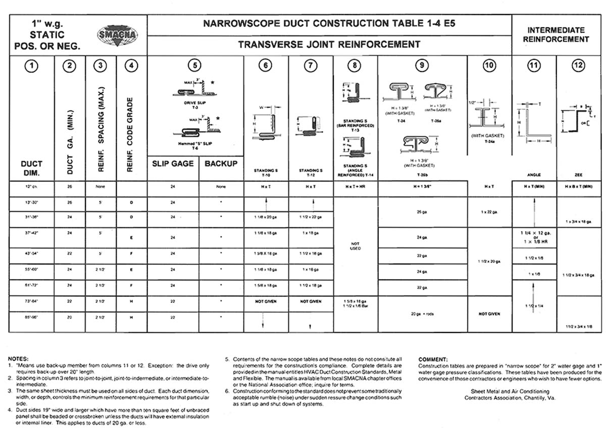
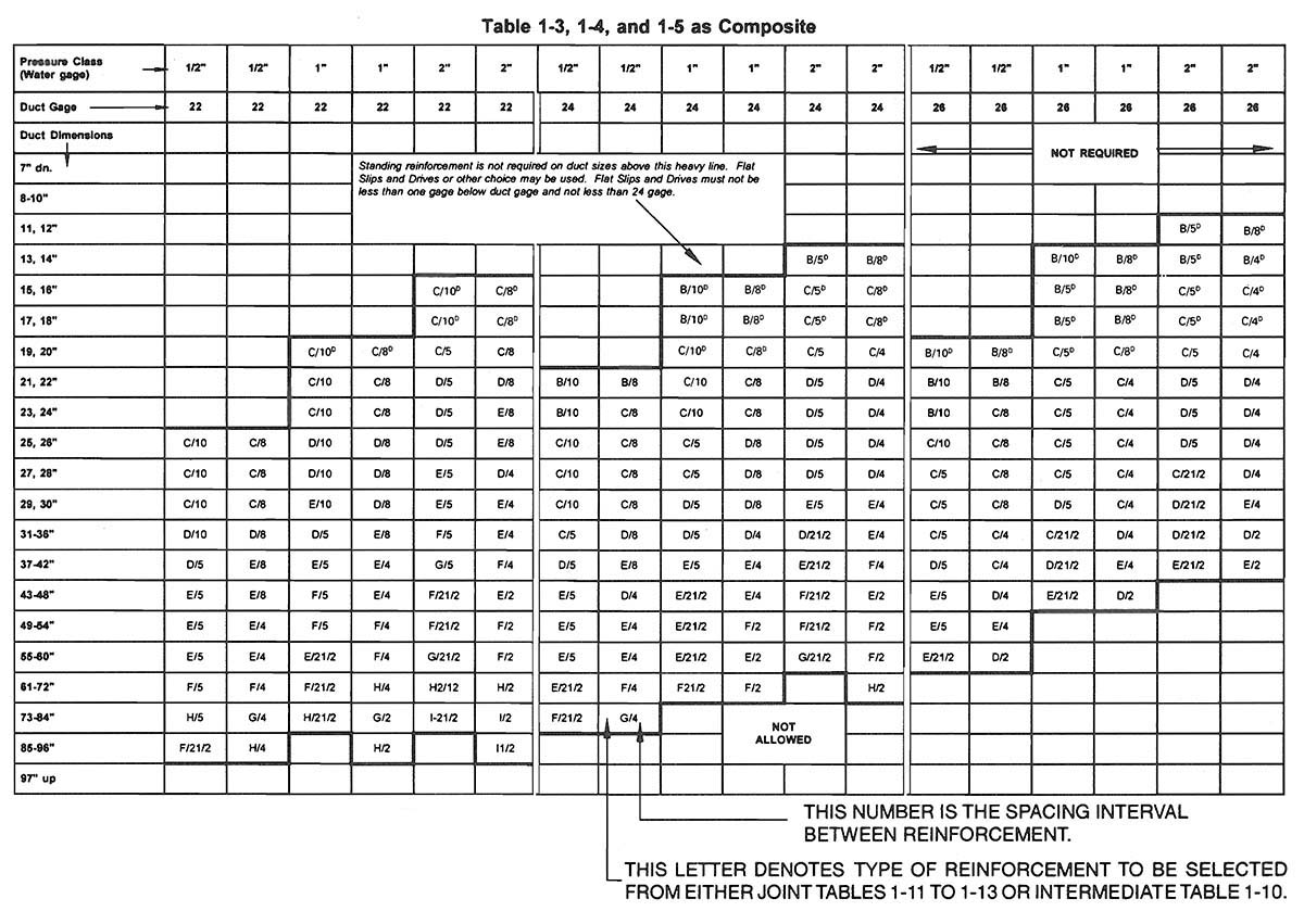
Flat Slips and Drives may be backed with Stiffeners from Table 1-10 and thereby qualified for this Table. Where the superscript D occurs, the flat drive is accepted as Class A, B, or C. See Table 1-25. Tie rod options are not listed here.
None of the requirements of the standards are waived by this chart.
A.17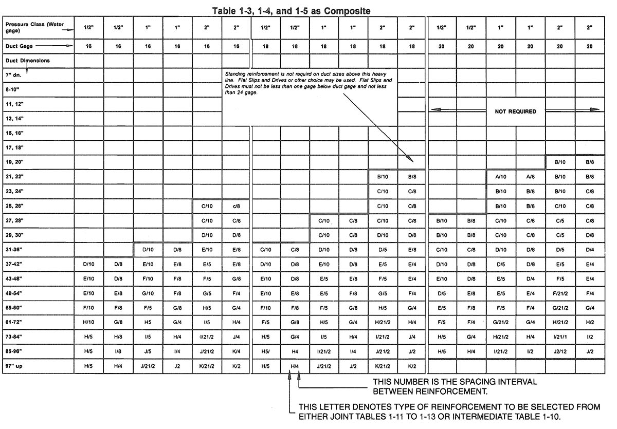
Flat Slips and Drives may be backed with Stiffeners from Table 1-10 and thereby qualified for this Table. Where the superscript D occurs, the flat drive is accepted as Class A, B, or C. See Table 1-25. Tie rod options are not listed here.
None of the requirements of the standards are waived by this chart.
A.18| DUCT Side | ||
| 10″ dn. | 26 ga. | No. Reinf. |
| 11″-26″ | 26 ga. | D @ 5′ |
| 27″-30″ | 24 ga. | E @ 5′ |
| 31″-42″ | 24 ga. | E @ 2 1/2′ |
| 43″-48″ | 24 ga. | F @ 2 1/2′ |
| 49″-54″ | 24 ga. | F @ 2 1/2′ |
| 55″-60″ | 24 ga. | G @ 2 1/2′ |
| 61″-72″ | 22 ga. | H @ 2 1/2′ |
| 73″-84″ | 22 ga. | I @ 2 1/2′ |
| 85″-96″ | 20 ga. | I @ 2 1/2′ |
| 97″-108″ | 18 ga. | J @ 2 1/2′ |
| DUCT Side | ||
| 10″ dn. | 26 ga. | No. Reinf. |
| 11″-20″ | 26 ga. | C joint |
| 21″-26″ | 26 ga. | D joint |
| 27″-30″ | 24 ga. | E joint |
| 31″-36″ | 22 ga. | F joint |
| 37″-42″ | 20 ga. | G joint |
| 43″-48″ | 20 ga. | H joint |
| 49″-54″ | 18 ga. | H joint |
| 55″-60″ | 18 ga. | I joint |
| 61″-72″ | 22 ga. | H @ 2 1/2′ |
| 73″-84″ | 22 ga. | I @ 2 1/2′ |
| 85″-96″ | 20 ga. | I @ 2 1/2′ |
| 97″-108″ | 18 ga. | J @ 2 1/2′ |
| DUCT Side | ||
| 10″ dn. | 26 ga. | No. Reinf. |
| 11″-22″ | 26 ga. | C @ 4′ |
| 23″-28″ | 26 ga. | D @ 4′ |
| 29″-36″ | 24 ga. | E @ 4′ |
| 37″-48″ | 24 ga. | F @ 3′ |
| 49″-54″ | 24 ga. | G @ 3′ |
| 55″-60″ | 22 ga. | G @ 3′ |
| 61″-72″ | 22 ga. | H @ 3′ |
| 73″-84″ | 18 ga. | I @ 4′ |
| 85″-96″ | 18 ga. | J @ 4′ |
| 97″-108″ | 18 ga. | K @ 3′ |
| DUCT Side | ||
| 10″ dn. | 26 ga. | No. Reinf. |
| 11″-22″ | 26 ga. | C joint |
| 23″-28″ | 26 ga. | D joint |
| 29″-36″ | 24 ga. | E joint |
| 37″-42″ | 24 ga. | F joint |
| 43″-48″ | 22 ga. | G joint |
| 49″-54″ | 20 ga. | H joint |
| 55″-60″ | 18 ga. | H joint |
| 61″-72″ | 18 ga. | I joint |
| 73″-84″ | 18 ga. | I joint |
| 85″-96″ | 22 ga. | I @ 2′ |
| 97″-108″ | 18 ga. | I @ 2′ |
D @ 5′, for example, means either a grade D joint or grade D intermediate member at a maximum interval of 5 ft.
A.20| W.G. STATIC POS.OR NEG. |
SHOP STANDARDS RECTANGULAR DUCT REINFORCEMENT |
||||||||
|---|---|---|---|---|---|---|---|---|---|
| NO REINFORCEMENT REQUIRED |
REINFORCEMENT CODE FOR DUCT GAGE NO. | ||||||||
| REINFORCEMENT SPACING OPTIONS | |||||||||
| DUCT DIMENSION |
10′ | 8′ | 6′ | 5′ | 4′ | 3′ | 21/2′ | 2′ | |
|
|
|
|
|
|
|
|
|
|
| 10″dn | |||||||||
| 11, 12″ | |||||||||
| 13, 14″ | |||||||||
| 15, 16″ | |||||||||
| 17, 18″ | |||||||||
| 19, 20″ | |||||||||
| 21, 22″ | |||||||||
| 23, 24″ | |||||||||
| 25, 26″ | |||||||||
| 27, 28″ | |||||||||
| 29, 30″ | |||||||||
| 31-36″ | |||||||||
| 37-42″ | |||||||||
| 43-48″ | |||||||||
| 49-54″ | |||||||||
| 55-60″ | |||||||||
| 61-72″ | |||||||||
| 73-84″ | |||||||||
| 85-96″ | |||||||||
| 97-108″ | |||||||||
| 109-120″ | |||||||||
DEPENDENT VARIABLES

REGULAR DUCTS
| MAXIMUM DEFLECTION | MAXIMUM TEST PREESURE | |
|---|---|---|
| JOINT and REINF. 1/4″ on 48″ w. W/200 on 49″-120″ |
SHEET: 3/8″ on 12″ Dn. 1/2″ on 13″-18″ 5/8″ on 19″-24″ 3/4″ on 25″-84″ 1″ on 85″-120″ |
LAB: CLASS RATING + 50% FIELD: CLASS RATING + 25% |
| TOLERANCE: +7.5% |
TOLERANCE: +10% |
| DUCT DIMENSION |
1/2 W.G. | 1 W.G. | 2 W.G. | 3 W.G. | 4 W.G. | 6 W.G. | 10 W.G. |
|---|---|---|---|---|---|---|---|
| 8″ DN. | NOT REQUIRED |
NOT REQUIRED |
NOT REQUIRED |
B @ 6′ | B @ 6′ | C @ 5′ | C @ 3′ |
| 9″ to 10″ | B @ 6′ | B @ 5′ | B @ 3′ | C @ 3′ | |||
| 11″ to 12″ | B @ 8′ | B @ 5′ | C @ 5′ | C @ 3′ | C @ 3′ | ||
| 13″ to 14″ | B @ 10′ | B @ 6′ | C @ 4′ | C @ 4′ | C @ 3′ | D @ 2 1/2′ | |
| 15″ to 16″ | B @ 8′ | C @ 5′ | C @ 4′ | C @ 4′ | D @ 3′ | D @ 2 1/2′ | |
| 17″ to 18″ | B @ 8′ | C @ 5′ | C @ 4′ | D @ 4′ | D @ 3′ | D @ 2 1/2′ | |
| 19″ to 20″ | B @ 10′ | C @ 8′ | C @ 5′ | C @ 3′ | D @ 3′ | D @ 2 1/2′ | NOT DESIGNED |
| 21″ to 22″ | B @ 10′ | C @ 6′ | D @ 5′ | D @ 3′ | D @ 3′ | E @ 2 1/2′ | |
| 23″ to 24″ | C @ 10′ | C @ 6′ | D @ 5′ | D @ 3′ | E @ 3′ | E @ 2 1/2′ | |
| 25″ to 26″ | C @ 10′ | C @ 6′ | D @ 5′ | D @ 3′ | E @ 3′ | NOT DESIGNED |
|
| 27″ to 28″ | C @ 8′ | D @ 6′ | D @ 4′ | E @ 3′ | E @ 3′ | ||
| 29″ to 30″ | C @ 8′ | D @ 6′ | E @ 4′ | E @ 3′ | E @ 3′ | ||
| 31″ to 36″ | C @ 6′ | D @ 4′ | E @ 3′ | E @ 2 1/2′ | F @ 2 1/2′ | ||
| 37″ to 42″ | D @ 5′ | E @ 4′ | E @ 2 1/2′ | E @ 2′ | F @ 2′ | ||
| 43″ to 48″ | E @ 5′ | E @ 3′ | E @ 2 1/2′ | NOT DESIGNED |
NOT DESIGNED |
||
| 49″ to 54″ | E @ 5′ | NOT DESIGNED |
NOT DESIGNED |
||||
| 55″ to 60″ | E @ 3′ | ||||||
| 61″ to 72″ | NOT DESIGNED |
||||||
| 73″ to 84″ | |||||||
| 85″ to 96″ | |||||||
| Over 96″ |
On items with “t”, tie rods must be used.
A.23| DUCT DIMENSION |
1/2 W.G. | 1 W.G. | 2 W.G. | 3 W.G. | 4 W.G. | 6 W.G. | 10 W.G. |
|---|---|---|---|---|---|---|---|
| 8″ DN. | NOT REQUIRED |
NOT REQUIRED |
NOT REQUIRED |
NOT REQUIRED |
NOT REQUIRED |
NOT REQUIRED |
C @ 5′ |
| 9″ to 10″ | B @ 6′ | C @ 5′ | C @ 4′ | ||||
| 11″ to 12″ | B @ 8′ | C @ 6′ | C @ 5′ | D @ 4′ | |||
| 13″ to 14″ | B @ 8′ | C @ 6′ | C @ 5′ | C @ 4′ | D @ 3′ | ||
| 15″ to 16″ | B @ 10′ | C @ 8′ | C @ 6′ | C @ 5′ | D @ 4′ | E @ 3′ | |
| 17″ to 18″ | B @ 10′ | C @ 8′ | D @ 6′ | D @ 5′ | E @ 4′ | E @ 3′ | |
| 19″ to 20″ | C @ 10′ | C @ 6′ | D @ 5′ | E @ 5′ | E @ 4′ | E @ 2 1/2′ | |
| 21″ to 22″ | B @ 10′ | C @ 10′ | D @ 6′ | D @ 5′ | E @ 5′ | F @ 4′ | F @ 2 1/2′ |
| 23″ to 24″ | C @ 10′ | C @ 10′ | D @ 6′ | E @ 5′ | E @ 4′ | E @ 3′ | F @ 2 1/2′ |
| 25″ to 26″ | C @ 10′ | D @ 8′ | E @ 6′ | E @ 5′ | E @ 4′ | F @ 3′ | F @ 2 1/2′ |
| 27″ to 28″ | C @ 10′ | D @ 8′ | E @ 5′ | E @ 4′ | F @ 4′ | F @ 3′ | G @ 2 1/2′ |
| 29″ to 30″ | C @ 10′ | D @ 8′ | E @ 5′ | E @ 4′ | F @ 4′ | F @ 3′ | H @ 2 1/2′ |
| 31″ to 36″ | D @ 8′ | E @ 6′ | E @ 4′ | F @ 3′ | F @ 3′ | G @ 2 1/2′ | H @ 2′ |
| 37″ to 42″ | E @ 8′ | E @ 5′ | F @ 4′ | F @ 3′ | G @ 2 1/2′ | NOT DESIGNED |
NOT DESIGNED |
| 43″ to 48″ | E @ 6′ | E @ 4′ | F @ 3′ | G @ 2 1/2′ | H @ 2 1/2′ | ||
| 49″ to 54″ | E @ 5′ | F @ 4′ | G @ 3′ | G @ 2 1/2′ | H @ 2′ | ||
| 55″ to 60″ | E @ 5′ | F @ 4′ | G @ 2 1/2′ | G @ 2′ | H @ 2′ | ||
| 61″ to 72″ | F @ 4′ | F @ 3′ | H @ 2′ | I @ 2′ | H @ 1 1/2′ | ||
| 73″ to 84″ | G @ 4′ | NOT DESIGNED |
NOT DESIGNED |
NOT DESIGNED |
NOT DESIGNED | ||
| 85″ to 96″ | NOT DESIGNED |
||||||
| Over 96″ |
On items with “t”, tie rods must be used.
A.24| DUCT DIMENSION |
1/2 W.G. | 1 W.G. | 2 W.G. | 3 W.G. | 4 W.G. | 6 W.G. | 10 W.G. |
|---|---|---|---|---|---|---|---|
| 8″ DN. | NOT REQUIRED |
NOT REQUIRED |
NOT REQUIRED |
NOT REQUIRED |
NOT REQUIRED |
NOT REQUIRED |
NOT REQUIRED |
| 9″ to 10″ | B @ 6′ | C @ 5′ | |||||
| 11″ to 12″ | B @ 10′ | C @ 6′ | D @ 5′ | ||||
| 13″ to 14″ | C @ 8′ | C @ 8′ | D @ 5′ | D @ 4′ | |||
| 15″ to 16″ | C @ 10′ | C @ 8′ | D @ 6′ | D @ 5′ | E @ 4′ | ||
| 17″ to 18″ | C @ 10′ | D @ 8′ | D @ 6′ | E @ 5′ | E @ 3′ | ||
| 19″ to 20″ | C @ 10′ | C @ 8′ | D @ 6′ | E @ 6′ | E @ 5′ | F @ 3′ | |
| 21″ to 22″ | C @ 10′ | D @ 8′ | E @ 6′ | E @ 5′ | F @ 5′ | F @ 3′ | |
| 23″ to 24″ | C @ 10′ | E @ 8′ | E @ 6′ | E @ 5′ | F @ 5′ | G @ 3′ | |
| 25″ to 26″ | C @ 10′ | D @ 10′ | E @ 8′ | E @ 6′ | F @ 5′ | F @ 4′ | G @ 3′ |
| 27″ to 28″ | C @ 10′ | D @ 10′ | E @ 6′ | F @ 5′ | F @ 5′ | G @ 4′ | H @ 3′ |
| 29″ to 30″ | C @ 10′ | E @ 10′ | E @ 6′ | F @ 5′ | G @ 5′ | G @ 4′ | H @ 3′ |
| 31″ to 36″ | D @ 10′ | E @ 8′ | F @ 5′ | F @ 4′ | G @ 4′ | H @ 3′ | H @ 2 1/2′ |
| 37″ to 42″ | E @ 8′ | E @ 6′ | F @ 4′ | G @ 4′ | G @ 3′ | H @ 2 1/2′ | I @ 2′ |
| 43″ to 48″ | E @ 8′ | F @ 5′ | G @ 4′ | G @ 3′ | H @ 3′ | I @ 2 1/2′ | I @ 2′ |
| 49″ to 54″ | E @ 6′ | F @ 5′ | G @ 3′ | H @ 3′ | H @ 2 1/2′ | I @ 2′ | H @ 1 1/2′ |
| 55″ to 60″ | F @ 6′ | G @ 5′ | G @ 3′ | H @ 2 1/2′ | I @ 2 1/2′ | I @ 2′ | H @ 1 1/2′ |
| 61″ to 72″ | F @ 5′ | H @ 4′ | H @ 3′ | I @ 2 1/2′ | I @ 2′ | H @ 1 1/2′ | NOT DESIGNED |
| 73″ to 84″ | H @ 5′ | H @ 3′ | I @ 2 1/2′ | I @ 2′ | I @ 1 1/2′ | J @ 1 1/2′ | |
| 85″ to 96″ | H @ 4′ | H @ 2′ | I @ 2′ | K @ 1 1/2′ | K @ 1 1/2′ | NOT DESIGNED |
|
| Over 96″ | NOT DESIGNED |
NOT DESIGNED |
NOT DESIGNED |
NOT DESIGNED |
NOT DESIGNED |
On items with “t”, tie must be used.
A.25| DUCT DIMENSION |
1/2 W.G. | 1 W.G. | 2 W.G. | 3 W.G. | 4 W.G. | 6 W.G. | 10 W.G. |
|---|---|---|---|---|---|---|---|
| 8″ DN. | NOT REQUIRED |
NOT REQUIRED |
NOT REQUIRED |
NOT REQUIRED |
NOT REQUIRED |
NOT REQUIRED |
NOT REQUIRED |
| 9″ to 10″ | C @ 6′ | ||||||
| 11″ to 12″ | C @ 10′ | D @ 6′ | |||||
| 13″ to 14″ | C @ 10′ | D @ 6′ | E @ 5′ | ||||
| 15″ to 16″ | C @ 8′ | D @ 8′ | D @ 6′ | E @ 5′ | |||
| 17″ to 18″ | D @ 8′ | D @ 8′ | E @ 6′ | F @ 5′ | |||
| 19″ to 20″ | C @ 10′ | D @ 8′ | E @ 8′ | F @ 6′ | F @ 4′ | ||
| 21″ to 22″ | C @ 10′ | D @ 10′ | E @ 8′ | E @ 6′ | F @ 6′ | G @ 4′ | |
| 23″ to 24″ | C @ 10′ | E @ 10′ | E @ 6′ | F @ 6′ | G @ 6′ | H @ 4′ | |
| 25″ to 26″ | D @ 10′ | E @ 10′ | E @ 6′ | F @ 6′ | G @ 5′ | H @ 4′ | |
| 27″ to 28″ | C @ 10′ | D @ 10′ | E @ 8′ | F @ 6′ | G @ 6′ | H @ 5′ | H @ 3′ |
| 29″ to 30″ | C @ 10′ | E @ 10′ | F @ 8′ | F @ 6′ | G @ 5′ | G @ 4′ | H @ 3′ |
| 31″ to 36″ | D @ 10′ | E @ 10′ | F @ 6′ | G @ 5′ | H @ 5′ | H @ 4′ | I @ 3′ |
| 37″ to 42″ | E @ 10′ | F @ 8′ | G @ 5′ | H @ 5′ | H @ 4′ | H @ 3′ | I @ 2 1/2′ |
| 43″ to 48″ | E @ 10′ | F @ 6′ | H @ 5′ | H @ 4′ | H @ 3′ | I @ 2 1/2′ | I @ 2′ |
| 49″ to 54″ | F @ 8′ | G @ 6′ | H @ 4′ | H @ 3′ | I @ 3′ | I @ 2 1/2′ | I @ 2′ |
| 55″ to 60″ | F @ 8′ | G @ 6′ | G @ 3′ | H @ 3′ | I @ 3′ | I @ 2 1/2′ | J @ 2′ |
| 61″ to 72″ | F @ 6′ | H @ 4′ | H @ 3′ | I @ 3′ | I @ 2 1/2′ | J @ 2′ | J @ 1 1/2′ |
| 73″ to 84″ | H @ 5′ | I @ 4′ | I @ 3′ | I @ 2 1/2′ | I @ 2′ | J 1 1/2′ | NOT DESIGNED |
| 85″ to 96″ | H @ 5′ | I @ 3′ | I @ 2 1/2′ | I @ 2′ | J @ 2′ | L @ 1 1/2′ | |
| Over 96″ | NOT DESIGNED |
NOT DESIGNED |
NOT DESIGNED |
NOT DESIGNED |
NOT DESIGNED |
NOT DESIGNED |
On items with “t”, tie rods must be used.
A.26| DUCT DIMENSION |
1/2 W.G. | 1 W.G. | 2 W.G. | 3 W.G. | 4 W.G. | 6 W.G. | 10 W.G. |
|---|---|---|---|---|---|---|---|
| 8″ DN. | NOT REQUIRED |
NOT REQUIRED |
NOT REQUIRED |
NOT REQUIRED |
NOT REQUIRED |
NOT REQUIRED |
NOT REQUIRED |
| 9″ to 10″ | |||||||
| 11″ to 12″ | C @ 8′ | ||||||
| 13″ to 14″ | D @ 8′ | ||||||
| 15″ to 16″ | D @ 10′ | E @ 6′ | |||||
| 17″ to 18″ | D @ 10′ | E @ 10′ | F@ 6′ | ||||
| 19″ to 20″ | D @ 10′ | E @ 10′ | F @ 8′ | G @ 6′ | |||
| 21″ to 22″ | D @ 10′ | E @ 10′ | E @ 10′ | F @ 8′ | H @ 6′ | ||
| 23″ to 24″ | E @ 10′ | E @ 10′ | F @ 10′ | G @ 8′ | H @ 6′ | ||
| 25″ to 26″ | E @ 10′ | F @ 10′ | G @ 8′ | G @ 6′ | H @ 5′ | ||
| 27″ to 28″ | D @ 10′ | F @ 10′ | F @ 8′ | G @ 8′ | H @ 6′ | I @ 5′ | |
| 29″ to 30″ | E @ 10′ | F @ 10′ | G @ 8′ | H @ 8′ | H @ 6′ | I @ 4′ | |
| 31″ to 36″ | D @ 10′ | E @ 10′ | G @ 8′ | H @ 6′ | H @ 6′ | I @ 5′ | I @ 4′ |
| 37″ to 42″ | E @ 10′ | F @ 10′ | G @ 6′ | H @ 6′ | I @ 5′ | I @ 4′ | I @ 3′ |
| 43″ to 48″ | E @ 10′ | G @ 8′ | H @ 6′ | I @ 5′ | I @ 5′ | I @ 4′ | J @ 3′ |
| 49″ to 54″ | F @ 10′ | H @ 8′ | H @ 5′ | I @ 5′ | I @ 4′ | I @ 3′ | J @ 2 1/2′ |
| 55″ to 60″ | G @ 10′ | H @ 8′ | I @ 5′ | I @ 4′ | H @ 3′ | J @ 3′ | K @ 2 1/2′ |
| 61″ to 72″ | H @ 8′ | H @ 6′ | I @ 4′ | I @ 3′ | J @ 3′ | J @ 2 1/2′ | L @ 2′ |
| 73″ to 84″ | H @ 6′ | I @ 5′ | I @ 4′ | J @ 3′ | J @ 2 1/2′ | K @ 2′ | L @ 1 1/2′ |
| 85″ to 96″ | I @ 6′ | I @ 4′ | J @ 4′ | K @ 3′ | K @ 2 1/2′ | L @ 2′ | M @ 1 1/2′ |
| 97″ to 108″ | NOT DESIGNED |
I @ 4′ | K @ 3′ | L @ 2 1/2′ | L @ 2 1/2′ | L @ 2′ | NOT DESIGNED |
| 109″ to 120″ | I @ 3′ | K @ 2 1/2′ | L @ 2 1/2′ | L @ 2 1/2′ | Kt @ 2′ |
On items with “t”, tie rods must be used.
A.27| DUCT DIMENSION |
1/2 W.G. | 1 W.G. | 2 W.G. | 3 W.G. | 4 W.G. | 6 W.G. | 10 W.G. |
|---|---|---|---|---|---|---|---|
| 8″ DN. | NOT REQUIRED |
NOT REQUIRED |
NOT REQUIRED |
NOT REQUIRED |
NOT REQUIRED |
NOT REQUIRED |
NOT REQUIRED |
| 9″ to 10″ | |||||||
| 11″ to 12″ | |||||||
| 13″ to 14″ | D @ 8′ | ||||||
| 15″ to 16″ | E @ 8′ | ||||||
| 17″ to 18″ | E @ 10′ | F @ 8′ | |||||
| 19″ to 20″ | E @ 10′ | F @ 10′ | G @ 8′ | ||||
| 21″ to 22″ | E @ 10′ | F @ 10′ | H @ 6′ | ||||
| 23″ to 24″ | F @ 10′ | G @ 8′ | H @ 6′ | ||||
| 25″ to 26″ | E @ 10′ | F @ 10′ | G @ 10′ | H @ 8′ | I @ 6′ | ||
| 27″ to 28″ | F @ 10′ | F @ 10′ | H @ 10′ | H @ 8′ | I @ 6′ | ||
| 29″ to 30″ | F @ 10′ | G @ 10′ | H @ 10′ | H @ 6′ | I @ 5′ | ||
| 31″ to 36″ | E @ 10′ | G @ 10′ | H @ 8′ | H @ 6′ | I @ 6′ | J @ 5′ | |
| 37″ to 42″ | E @ 10′ | F @ 10′ | H @ 8′ | H @ 6′ | I @ 6′ | I @ 5′ | J @ 4′ |
| 43″ to 48″ | E @ 10′ | G @ 10′ | I @ 8′ | I @ 6′ | I @ 5′ | I @ 4′ | J @ 3′ |
| 49″ to 54″ | F @ 10′ | H @ 10′ | I @ 6′ | I @ 5′ | I @ 5′ | J @ 4′ | K @ 3′ |
| 55″ to 60″ | G @ 10′ | H @ 8′ | I @ 6′ | I @ 5′ | J @ 5′ | J @ 3′ | L @ 3′ |
| 61″ to 72″ | H @ 10′ | H @ 6′ | J @ 5′ | J @ 4′ | J @ 3′ | K @ 3′ | L @ 2 1/2′ |
| 73″ to 84″ | I @ 8′ | I @ 6′ | I @ 4′ | J @ 3′ | K @ 3′ | L @ 2 1/2′ | L @ 2′ |
| 85″ to 96″ | I @ 8′ | I @ 5′ | J @ 4′ | K @ 3′ | K @ 2 1/2′ | L @ 2′ | Lt @ 2′ |
| 97″ to 108″ | I @ 5′ | I @ 4′ | K @ 3′ | L @ 2 1/2′ | L @ 2 1/2′ | L @ 2′ | Lt @ 2′ |
| 109″ to 120″ | I @ 3′ | I @ 3′ | K @ 2 1/2′ | L @ 2 1/2′ | L @ 2 1/2′ | Jt @ 2 1/2′ | Lt @ 2′ |
On items with “t”, tie rods must be used.
A.28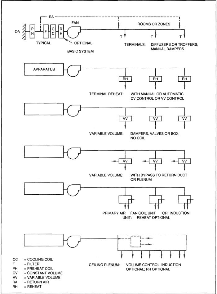
SINGLE PATH AIR SYSTEMS
A.29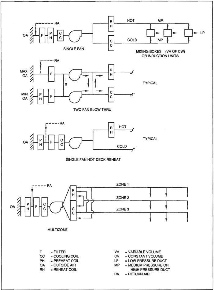
DUAL PATH AIR SYSTEMS
A.30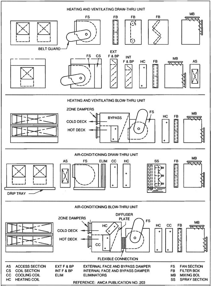
TERMINOLOGY FOR CENTRAL STATION APPARATUS
A.31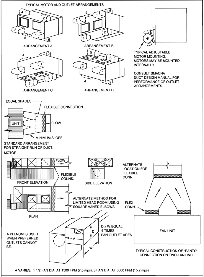
TYPICAL HVAC UNIT CONNECTIONS
A.32
MOTOR ARRANGEMENTS
A.33
FAN ROTATION & DISCHARGE POSITIONS
A.34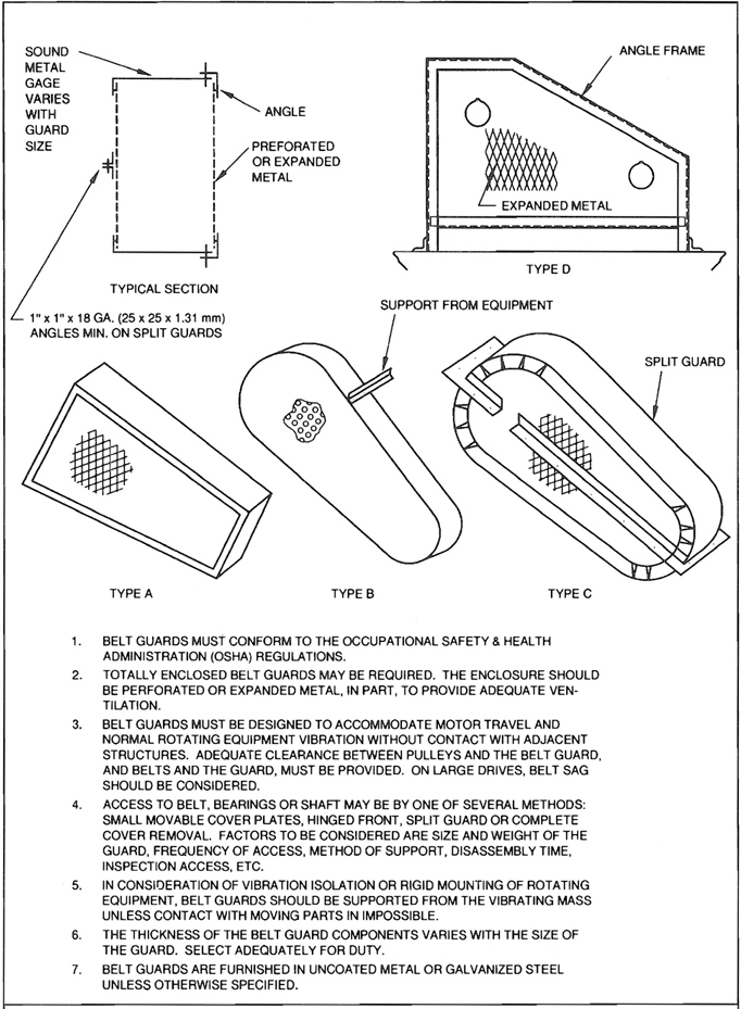
TYPICAL BELT GUARDS
A.35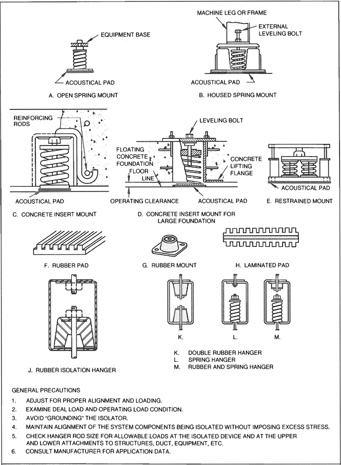
TYPICAL ISOLATION DEVICES
A.36The purpose of these data sheets is to acquaint the air conditioning engineer with means for shielding ductwork and other openings that penetrate protective barriers around radiation facilities, particularly X-ray rooms.
Protection against radiation from X-ray tube, cyclotron, radium, or other radioactive material is primarily a question of shielding to reduce the level of radiation to a safe or specified amount, of maintaining safe distances from the rays, and/or of limiting the time of exposure
The prime consideration in preventing penetration of rays is is density of the shielding material. Lead is the densest of any commonly available. Where space is at a premium, particularly in modern buildings, and where utmost radiation protection is demanded, lead is invariably used. Lead is useful, especially where neutron and gamma rays are concerend, in that it does not itself become contaminated and emit harmful rays.
Lead, usually in sheet form, is used to line the walls, floor, and often the ceiling of rooms containing radiation facilities. Openings through the barrier for air ductwork, piping, service boxes, conduit, etc., require shielding, usually obtained by a lead barrier around or behind these building utilites of sufficient coverage and thickness to prevent penetration of these rays.
Shielding of duct and other openings in the protective barriers of radiation facilities depends on energy of radiation, orientation of the beam, dimensions, and location of opening in the protective barrier, geometrical relationship between the radiation source and opening, and geometrical relationship between opening and perons, materials, or instruments to be protected. The complexity of these factors requires the services of a radiological physicist, who determines extent of shielding, materials for shielding (usually lead or concrete) and the thickness of the shielding material.
*Mr. Goodman, formerly with Meyer, Strong, and Jones now has his own consulting practice in New York City. He has a masters degree in mechanical engineering from the University of Wisconsin, where he specialized in heat transfer, and is a licensed professional engineer.
**Mr. Hollands is chief engineer, in charge of design of radiation shielding materials and equipment, for Bar-Ray Products, Inc., Brooklyn, N. Y. He is a member of ASTM, Society for Nondestructive Testing, Accoustical Society of America, and American Institute of Physics.
After the radiological physicist has done the basic design for this shielding, the protective barrier contractor provides the required shielding for the opening.
Design of ductwork, piping, etc., should anticipate some of the problems encountered both in the design and installation of shielding. Also, coordination between air conditioning contractor and shielding fabricator can best be achieved by understanding and forethought on the part of the air conditioning designer.
Figures 1 to 4 give some idea of the area of shielding required around ductwork. They show various duct installations which penetrate the protective barrier for walls or partitions of X-ray rooms. Lead shielding is used to cover these openings, the approximate extent of which is indicated in terms of simple equations in involving the opening dimensions and wall thickness. These are conservative estimates, which will aid the air conditioning designer to understand what what to expect as to the area of shielding ductwork. The radiological physicist actually determines for each case the lead thickness and the exact amount of shielding required.
Note in Figure 4 that the protective shielding deals with primary radiation, while Figures 1 to 3 show protection against scattered or secondary radiation. Primary radiation comes directly from the source; scattered radiation has been deviated in direction; and secondary radiation is emitted by an irradiated material. Primary radiation requires more protection because its energy level is higher.
Sheet lead is not structurally self-supporting, so must be mounted to prevent sagging by its own weight. For lead thickness up to 3.5 mm, sheet lead can be readily shaped around round and small rectangular ducts, say 24″ maximum diameter or width, with all joints overlapping at least 1/2″. To hold these lead sheets in place, 1″ wide iron bands should be placed around the periphery of the duct on approximately 12″ centers, care being taken not to cut into the lead when the bands are bolted up.
When lead thickness is greater than 3.5 mm or duct or duct width exceeds 24″, lead shielding should be laminated on a plywood or similar structural core, which is made in sections or panels to conform to the sides of the duct. The laminated sections are mechanically fastened at the seams and corners. These joints are lapped with sheet lead angles or lead strips, the width of which is twice the thickness of the lead, but not less than 1/2 A.37 inch in any case. Nails, bolts, screws, or other fasteners used to secure the lead sheet or panel must be covered with lead of thickness equal to the lead sheet. Lead headed nails may be used as shown in Figure 5.
For lead shielding of 1.0 mm or less, flexible leaded vinyl sheets can be used for easy forming to complex shapes and contours. The flexible leader vinyl sheets can be applied in layers where heavier than 1.0 mm lead shielding is required. If the duct has a flexible vinyl sheets could be applied over it more readily than other forms of shielding.
Duct hangers are best installed on the outside of the lead shielding so that the hanger rods or straps do not have to pierce the shielding. The lead shielding adds considerably to the weight of the duct and the hangers should be substanial, with such adequate anchoring in the slab above as fish plates. For rectangular ducts, trapeze hangers would be the most practical. For design purposes, estimate each 1/16″ of lead at 4 lb. per sq. ft.
Tests for radiation leakage are usually made after the room is finished and the equipment is installed. It is very important to install shielding properly during the course of construction because of the expense in making corrections to the finished protective barrier. Moreover, equipment such as dampers should never be put in the shielded section of the ductwork, as repairs to this equipment would be very costly if the shielding must be dismantled.
A simple way to avoid penetration of the protective barrier’s lead lining by pipes or wires is to offset them as close behind the lead lining as possible so that they can be backed with a lead sheet of sufficient size to prevent passage of the rays at any angle. This lead patch method is also used for electric switch boxes located in the wall.
The extent of the protective barrier for medical installations is summarized below so that the air conditioning designer can tell whether ducts or pipes running through such spaces are likely to be a problem. For medical radiographic and fluoroscopic rooms the lead shielding generally does not extend above a line 7″, 0″. from the finished floor; and if the service lines and ducts can be located above this line, shielding around them is obviously unnessary. For X-ray therapy rooms, lead shielding may extend to the ceiling or structural slab. The ceiling or slab above and the floor may also be lead lined, depending upon output of the machine and other conditions. For industrial X-ray work, wall shielding may extend to the ceiling. Both ceiling and floor in some cases will require lead lining.
For shielding in supervoltage rooms, special conditions may apply. In any event, the radiological physicist should be consulted to design the proper protection. Where concrete is considered for the shielding material, it is often more practical to use lead of equivalent value for the shielding of openings. Where recesses occur in concrete barriers for equipment, lead backing, equivalent to the thickness of the concrete removed, should be provided.
Of the many publication available on the subject of radiation protection, these two are the most useful:
In addition, the New York City Health Department publishes the New York City Health Code requirements dealing with radiological hazards (Article 175).
Notice: This article and associated drawings are reproduced from a 1984 printing of A Guide to The Use of Lead For Radiation Shielding with permission of the Lead Industries Association.
A.38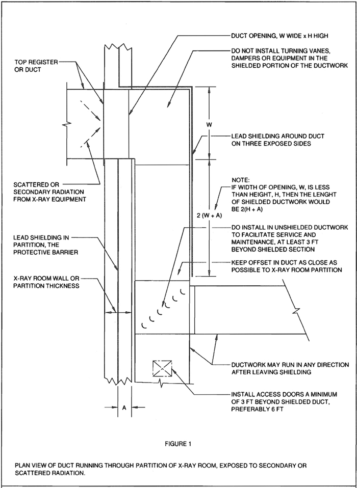
RADIATION PROTECTION AT WALL OPENINGS
A.39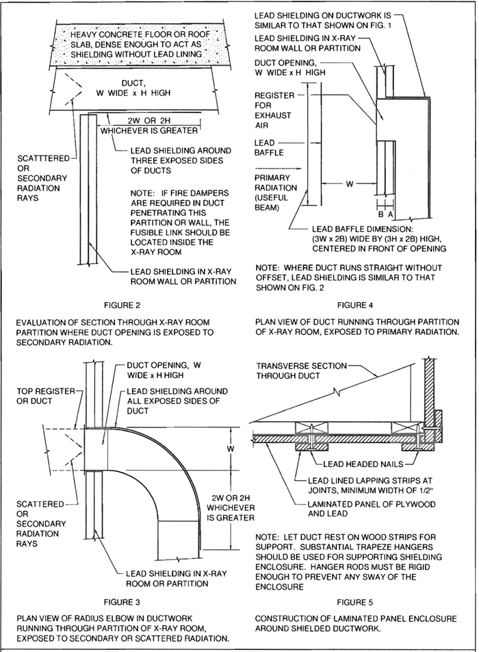
RADIATION PROTECTION AT WALL OPENINGS
A.40
NUMBER OF SHORT RADIUS VANES
A.41
NUMBER OF SHORT RADIUS VANES (METRIC)
A.42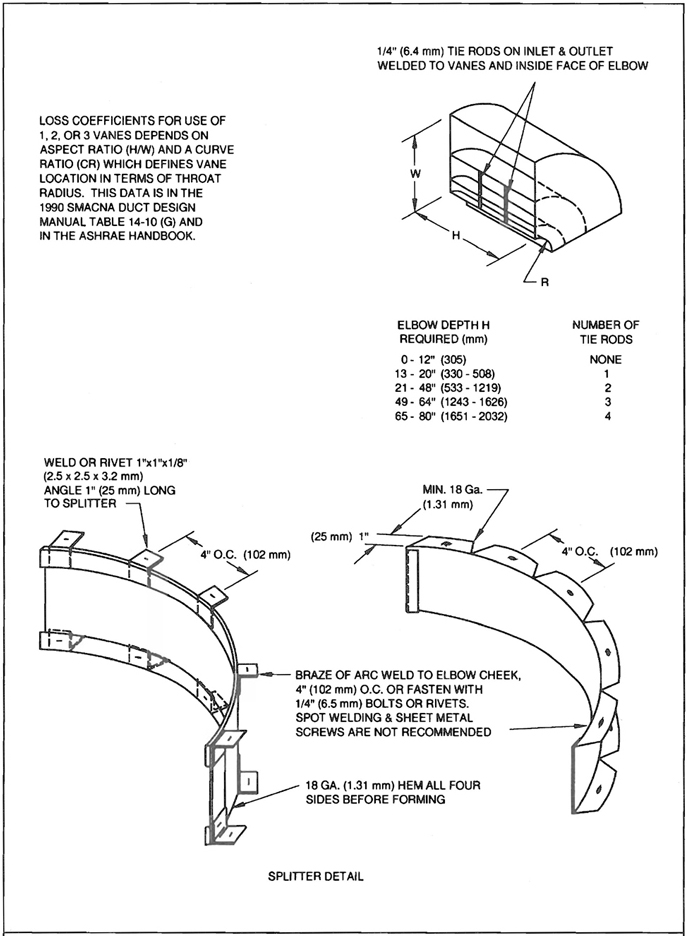
CONSTRUCTION OF SHORT RADIUS VANES
A.43Low Velocity Systems Duct Manual
1st Edition, 1959, Committee
Angelo Hoffman, Chairman, Milwaukee, WI
John John Creegan, Hawthorn, NJ
Charles H. Johnson, East Moline, IL
Lawrence Paul, Chicago, IL
D.E. Mannen, Cleveland, OH
Paul Stromberg, Washington, DC
Harold C. Stevens, Chicago, IL
2nd Edition, 1963, Committee
J. Frank Park, Chairman, Compton, CA
John John Creegan, Hawthorn, NJ
M. A. Punchard, Fort Worth, TX
Harold C. Stevens, Chicago, IL
Robert Schomann, Milwaukee, WI
3rd Edition, 1967, Committee
J. Frank Park, Chairman, Compton, CA
Arnold N. Brodie, Oak Park, MI
Isidore Jacobson, Cincinnati, OH
D. E. Mannen, Cleveland, OH
M. A. Punchard, Fort Worth, TX
Harold C. Stevens, Chicago, IL
Low Velocity Duct Construction Standard
4th Edition, 1969, Committee
J. Frank Park, Chairman, Compton, CA
Isidore Jacobson, Cincinnati, OH
D. E. Mannen, Cleveland, OH
M. A. Punchard, Fort Worth, TX
Harold C. Stevens, Chicago, IL
Low Pressure Duct Construction Standard
5th Edition, 1976, Committee
Earl Burmeister, Chairman, Des Moines, IA
Claude Wilson, Bozeman, MT
Richard Friedman, Richmond, CA
Robert Gawne, Washington, DC
John Stratton, Vienna, VA
Robert Tumberger, Chairman, Kansas City, MO
Frank Swanda, Chairman, Oklahoma City, OK
Ernest Boniface, Wayne, NJ
John Burnett, Phoenix, AZ
Dick Cramer, Flint, MI
Floyd Deeds, Salt Lake City, UT
Warren Hanna, Farmingham, MA
Fred Hershman, Philadelphia, PA
John Higgins, St. Louis, MO
Ron Keeler, Edmonton, Alberta, Canada
D. C. Lee, Birminghan, AL
Bill Orchard, North Brunswick, NJ
John Paoluccio, Modesto, CA
Wayne Parriot, St. Paul, MN
James Ray, Atlanta, GA
Gordon Root, Burlington, VT
Harold Stevens, Chicago, IL
Gene Van Dyke, Denver, CO
Test Program: Pat Bentz, Vienna, VA
High Velocity Duct Systems Manual
1st Edition, 1965, Commitee
Donal J. Mosshart, Jr., Chairman, Pittsburgh, PA
Gilbert G. Dorsett, Dallas, TX
William M. Harmon, Columbus, OH
Richard Peabody, Philadelphia, PA
Jerome C. Ross, New York, NY
High Velocity Duct Construction Standards
2nd Edition, 1969, Committee
Donal J. Moshart, Jr., Chairman, Pittsburgh, PA
Lawrence O. Paul, Chicago, IL
Gilbert G. Dorsett, Dallas, TX
Richard Peabody, Philadelphia, PA
Jerome C. Ross, New York, NY
High Pressure Duct Construction Standards
3rd Edition, 1975, Committee
Bowman Turner, Chairman, Columbus, OH
Gilbert Wood, Houston, TX
John Gruss, Kansas City, MO
Floyd Deeds, Salt Lake City, UT
John H. Stratton, Vienna, VA
Test Program: Pat Bentz, Vienna, VA
Duct Liner Application Standard
1st Edition, 1971, Committee
Joseph B. Whatley, Chairman, Tampa, FL
G.E. Daniel, St. Petersburg, FL
Bill R. Svejkovsky, Oklahoma City, OK
Robert Segal, Farmington, MI
Harold Stevens, Chicago. IL
Robert W. Boltz, Arlington, VA
Robert G. Sandvik, Arlington, VA
National Insulation Manufacturers Association
Adhesive And Sealant Council, Inc.
Duro-Dyne Corporation
Gripnail Corporation
Omark Industries
Stic-Klip Company
Duct Liner Application Standard
2nd Edition, 1975, Committee
Joseph B. Whatley, Chairman, Tampa, FL
G.E. Daniel, St. Petersburg, FL
Bill R. Svejkovsky, Oklahoma City, OK
Robert Segal, Farmington, MI
Gerard Iacouzze, Vienna, VA
Therman Insulation Manufacturers Association
Flexible Duct Installation Standards
1st Edition, 1979, Fibrous Products Committee
Robert E. Taylor, Chairman, Salt Lake City, UT
Burton H. Anderson, San Leandro, CA
G. E. Daniel, St. Petersburg, FL
Daniel J. Driscoll, Philadelphia, PA
Wallace E. Fizer, Lexington, KY
Robert Gawne, Washington, DC
Harold Nepereny, Vienna, VA
2nd Edition, 1980, Fibrous Products Committee
Robert E. Taylor, Chairman, Salt Lake City, UT
John Aimonette, Ft. Lauderdale, FL
Daniel J. Driscoll, Philadelphia, PA
Wallace E. Fizer, Lexington, KY
Harold Nepereny, Vienna, VA
HVAC Duct Construction Standards-Metal and Flexible
1st Edition, 1985, Commitee
Thomas J. Boniface, Chairman, Wayne, NJ
Earl Burmeister, Chairman 1976 to 1983, W. Des Moine, IA
Robert S. Deeds, Salt Lake City, UT
Frank D. Ellis, Sparks, NV
Norman T. R. Heathorn, Oakland, CA
William J. Knecht, Camden, NJ
Daniel Steimer, Portland, OR
John H. Stratton, Vienna, VA
Floyd W. Deeds, Salt Lake City, UT
Richard Friedman, Richmond, CA
John J. Gruss, Shawnee Mission, KS
Joe Hunter, Falls Church, VA
Claude Wilson, Bozeman, MT
Donald Partney, Granite City, IL
Fibrous Products Standards Commitee
Contributors to Duct Liner and Flexible Duct
Sections of the HVAC-DCS, First Edition
John Aimonette, Chairman, Ft. Lauderdale, FL
Robert E. Taylor, Salt Lake City, UT
Keith Pierson, Sacramento, CA
Herbert Delasco, South Windsor, CT
Joe Ibsen, San Bernardino, CA
Daniel J. Driscoll, Philadelphia, PA
| RECTANGULAR SIZES |
GAGES OF SHEETS FOR DUCT SIZES |
ROUND DIAMETER |
|---|---|---|
| Up to 12 in. | 26 | Up to 12 in. |
| 13 to 30 in. | 24 | 13 to 30 in. |
| 31 to 42 in. | 22 | 31 to 40 in. |
| 43 to 60 in. | 20 | 41 to 60 in. |
| 61 in. and over | 18 | 61 in. and over |

SHEET METAL AND AIR CONDITIONING CONTRACTORS’ NATIONAL ASSOCIATION, INC.
HEADQUARTERS: 4201 LAFAYETTE CENTER DRIVE • CHANTILLY, VIRGINIA 20151-1209
MAILING ADDRESS: P.O. BOX 221230 • CHANTILLY, VA 20153-1230
PHONE: (703) 803-2980 • FAX: (703) 803-3732
Copyright 1997
All Rights Reserved
x xi| STANDARD VERSION | ||
| MODEL PROJECT SPECIFICATION - AMENDMENT | xiii | |
| GENERAL REQUIREMENT FOR MIDPANEL TIE ROD (MPT) USE | 1.41.1 | |
| MIDPANEL TIE ROD (MPT) USE GUIDE | ||
| GENERAL PROCEDURE | 1.41.2 | |
| MPT SELECTION EXAMPLES | 1.41.3 | |
| MIDPANEL TIE ROD (MPT) SCHEDULE | TABLE 1-10S | 1.41.5 |
| MPT USE SCHEDULES | ||
| 1/2″ W.G | TABLE 1-3S | 1.41.6 |
| 1″ W.G | TABLE 1-4S | 1.41.6 |
| 2″ W.G | TABLE 1-5S | 1.41.6 |
| 3″ W.G | TABLE 1-6S | 1.41.7 |
| 4″ W.G | TABLE 1-7S | 1.41.7 |
| 6″ W.G | TABLE 1-8S | 1.41.7 |
| MPT DESIGN LOAD IN POUNDS | TABLE 1-14S | 1.44.1 |
| MPT SIZE - STEEL RODS | TABLE 1-15S | 1.46.1 |
| MPT SIZE - EMT | TABLE 1-18S | 1.52.1 |
| METRIC VERSION | ||
| GENERAL REQUIREMENT FOR MIDPANEL TIE ROD (MPT) USE | 1.41.1M | |
| MIDPANEL TIE ROD (MPT) USE GUIDE | ||
| GENERAL PROCEDURE | 1.41.2M | |
| MPT SELECTION EXAMPLES | 1.41.3M | |
| MIDPANEL TIE ROD (MPT) SCHEDULE | TABLE 1-10SM | 1.41.5M |
| MPT USE SCHEDULES | ||
| 125 Pa. | TABLE 1-3SM | 1.41.6M |
| 250 Pa. | TABLE 1-4SM | 1.41.6M |
| 500 Pa. | TABLE 1-5SM | 1.41.6M |
| 750 Pa. | TABLE 1-6SM | 1.41.7M |
| 1000 Pa. | TABLE 1-7SM | 1.41.7M |
| 1500 Pa. | TABLE 1-8SM | 1.41.7M |
| MPT DESIGN LOAD IN KILOGRAMS | TABLE 1-14SM | 1.44.1M |
| MPT SIZE - STEEL RODS | TABLE 1-15SM | 1.46.1M |
| MPT SIZE - EMT | TABLE 1-18SM | 1.52.1M |
AMENDMENT TO MODEL PROJECT SPECIFICATION SECTION 1.0, Page xiii
| 1.0 DUCT CONSTRUCTION
Ductwork and supports shall conform to the HVAC Duct Construction Standards, Metal, and Flexible, Second Edition, 1995, including Addendum No. 1, dated November 1997. Where fittings of configurations not shown in the HVAC-DCS are shown on the contract drawings, they shall be constructed as though they were therein. |
Addendum No. 1 contains prescriptive standards for use of internal tie rods at midpanel in lieu of Table 1-10 external reinforcements. |
| 1.1 DUCT DIMENSIONS
Duct dimensions shown on the contract drawings are for airflow area. When ducts are acoustically lined, their dimensions shall be increased as necessary. |
|
| 1.2 DUCT PRESSURE CLASS
Duct pressure classes are identified on the contract drawings. |
Schedule the pressure classes here by fan system number, or portion thereof, if they are not shown on the drawings. |
| 1.3 DUCT SEAL CLASS
Ducts shall be sealed as specified in the HVAC-DCS. |
Review DCS pages 1-7 to 1-9. |
| 1.4 DUCT LEAKAGE CLASS | Consult the HVAC-Air Duct Leakage Test Manual and select appropriate allowable leakage. If field leak tests are required, appropriate test pressures and clear scope of testing must be specified. |
| 1.5 DUCT LINER
Metal nosing shall be used on leading edges of each piece of lined duct when the velocity exceeds 4000 fpm (20.3 m/s). Otherwise, it shall be used on the leading edge of any lined duct section that is preceded by unlined duct. |
See duct liner text and references in the HVAC-DCS and specify the material, thickness, density, and performance characteristics desired. |
| 1.6 FLEXIBLE DUCT AND CONNECTOR
Where the specifications for connecting and supporting these in the HVAC-DCS are more stringent or restrictive, they shall supersede. |
Consult the applicable codes, the U.L. Fire Resistance Directory, references in the HVAC-DCS, the Air Diffusion Council’s Flexible Air Duct Performance and Installation Standards and identify the products and performance characteristics desired. |
| 1.7 VIBRATION ISOLATION CONNECTORS
Flexible isolation connectors shall not exceed 10 inches in length in direction of airflow and shall be made of flame retardant fabric fabric having a flame spread rating not over 25 and a smoke developed rating not over 50. |
General Requirements for Midpanel Tie Rod (MPT) Use:
General Procedure:

Example No. 1:
48″ × 18″ duct, 2″ w.g. positive pressure per Table 1-5; 5 ft. joint spacing; T-25a or T-25b joints:
In Table 1-5 for 48″ width, Column 6 gives reinforcement for 5’ RS (reinforcement spacing) as H-20 and Column 9 for 2 1/2’ RS as F-24; these are basic alternatives, but the joint ratings must be checked for duct gage override per text sections 1.8.4 on page 1.15 and S1.13 and S1.14 on page 1.17.
Therefore, for 5’ RS option Table 1-12 shows T-25 joints of H Code requiring 18 gage duct wall to satisfy the H joint rating; however, T-25 of 20 gage with tie rods at the joints (JTR) is I Code which satisfies both Tables 1-5 and 1-12. No between joint reinforcement is required. On the 18″ wide sides, Column 2 shows that reinforcement is not required.
For 48″ width, the alternative of 2-1/2’ RS would only require 24 gage duct wall per Table 1-5, Column 9, but the F Code in Table 1-12 requires the use of T-25 of 22 gage duct wall, an override upgrade from Table 1-5. No tie rod is required at the joint, but one must be used at mid panel between joints (unless external reinforcement per Table 1-10 is used there). 22 gage metal will be used on all four sides; see text section 1.8.1 (3) on page 1.12. On the 18″ side, T-25 of 22 gage is F Code (which exceeds the C Code required in Column 9 of Table 1-5).
Table 1-5S shows in Column 9 for 48″ width that 22 gage is required for T-25 joints. This gage is correct for external reinforcements as well as for midpanel tie rod (MPT) cases. See Note 2b under Table 1-5S.
To select the MPT for 2-1/2’ RS, Note 4 of Table 1-5S says go to Table 1-15S. In Table 1-15S, 1/4″ rod and 1/2″ EMT preselected options are given; however, as Note 5 with Table 1-15S and Note 5 of the General Requirements for MPT use indicate straps, pipes, angles or RC conduit are other, perhaps less economical, alternatives.
The requirements for tie rods at T-25 joints are the same as they would be for external reinforcement systems. The joints must qualify independently according to the reinforcement interval. For the conditions in Example No. 1, rods at T-25 joints are only required for 5’ RS intervals. Therefore, the rod size for the joint is selected based on one rod per Fig. 1-2(G) or two rods per Fig. 1-3(D) and the load from Table 1-14. In Table 1-14, the load for 2″ w.g. and 5’ RS on 48″ width is 156 pounds (for one rod or 78 pounds for each of two). From Table 1-15, 1/4″ rod suffices. From paragraph S1.19.4 on page 1.40, 1/2″ EMT is adequate.
Example No. 2:
The duct is the same as in Example No. 1 except the pressure is 2″ w.g. negative.
Gage, joint qualification and RS options are as for positive pressure. Tie rod loads in Table 1-14S are also the same.
To select the MPT of EMT, find in Table 1-18S that 1/2″ diameter EMT is adequate at 2-1/2’ RS up to 46″ length. To consider steel rod Table 1-14S gives (at 48″ width, 30″ RS and 2″ w.g.) 104 pounds. Then Table 1-16 shows that 1/2″ steel rod is required for 18″ length (to avoid buckling with a reasonable safety factor).
1.41.3Example No. 3:
72″ × 54″ duct at 3″ w.g. negative pressure with 4’ joint spacing and 2’ RS; use standing S or T-25 joints.
Table 1-6 has I-24G on 72″ width and G-24 on 54″ width.
Table 1-6S and Table 1-10S show that on 72″ width, two MPT are required on 24 gage and 22 gage duct; however, Table 1-10S also shows that if the duct was 20 gage only one MPT tie rod is required. Both tables show that only one MPT tie rod is required on 54″ width.
Standing S joints cannot be used because notes on pages 1.34 and 1.63 limit their use to 36″ width. For T-25 joints, Table 1-12 shows that the gage must be 22 minimum and tie rods must be used to obtain the joint rating.
EMT tie rods must per Table 1-18S be 3/4″ diameter for the 72″ panels and 1″ diameter for the 54″ panels (because of the lengths). Crossing tie rods must comply with S 1.25 on page 1.41. Steel rod ties were not sized in Table 1-16 for lengths over 42″ because other options appear more practical and economical.
EMT tie rods at T-25 joints would per Table 1-14 have to satisfy 142 and 105 pound loads for the associated lengths. EMT rods could be used from Table 1-18S because they have 25% more load capacity per Table 1-14S criteria (notes) than Table 1-14. However, in this case, Table 1-18 would require (based on length) the same sizes as those used at midpanel; that is, 1″ diameter and 3/4″ diameter.
If Example No. 3 had dealt with positive pressure, Note 3 with Table 1-15S applies for MPT steel rods (i.e., 3/8″ diameter minimum) and, for EMT per Table 1-15S, 1/2″ diameter is sufficient. By comparison of Tables 1-15S and 1-15 plus text S1.19.4 on page 1.40 for EMT, it is seen that Table 1-15S can also be used for rods and EMT at joints.
1.41.4| RS | 16 GA. | 18 GA. | 20 GA. | 22 GA. | 24 GA. | 26 GA. | |
|---|---|---|---|---|---|---|---|
| ± 1/2″ W.G. |
3′ 2-1/2′ 2′ |
To 96(1) To 96(1) To 96(1) |
To 84(1) To 84(1) To 84(1) |
To 54(1) To 60(1) To 60(1) |
|||
| ±1″ W.G. |
3′ 2-1/2″ 2′ |
To 96(1)* To 96(1)* To 96(1)* |
To 84(1)* 85-96(2) To 84(1)* 85-96(2) To 84(1)* 85-96(2) |
To 72(1)* 73-84(2) To 72(1)* 73-84(2) To 72(1) 73-96(2) |
To 60(1) 61-72(2) To 60(1) 61-72(2) To 72(1) |
To 42(1) To 48(1) To 48(1) |
|
| ±2″ W.G. |
3′ 2-1/2′ 2′ |
To 84(1)* To-96(2) To 84(1)* 85-96(2) To 96(1)* |
To 60(1)* 61-84(2) To 72(1)* 73-96(2) To 72(1)* 73-96(2) |
To 48(1)* 49-72(2) To 60(1)* 61-84(2) To 60(1) 61-96(2) |
To 42(1) 43-54(2) To 54(1) 55-60(2) To 60(1) 61-72(2) |
N/A To 42(1) To 42(1) |
|
| ±3″ W.G. |
3′ 2-1/2′ 2′ |
To 72(1)* 73-84(2) To 72(1)* To 96(2) To 84(1)* 85-96(2) |
To 54(1)* 55-72(2) To 60(1)* 61-84(2) To 72(1)* 73-96(2) |
To 48(1) 49-54(2) To 54(1)* 55-72(2) To 60(1)* 61-84(2) |
To 42(1) To 42(1) 43-54(2) To 54(1) 55-72(2) |
N/A N/A To 42(1) |
|
| ±4″ W.G. |
3′ 2-1/2′ 2′ |
To 84(2) | To 60(1)* 61-72(2) To 72(1)* 73-96(2) To 84(1)* 85-96(2) |
To 54(1)* 55-60(2) To 60(1)* 61-72(2) To 60(1)* 61-96(2) |
To 48(1) 49-60(2) To 48(1) 49-60(2) To 60(1) 61-72(2) |
N/A N/A N/A |
N/A N/A N/A |
| ±6″ W.G. |
3′ 2-1/2″ 2′ |
To 72(2) To 96(2) |
To 54(1)* 55-60(2) To 72(1)* To 72(1)* 73-96(2) |
To 42(1)* 43-60(2) To 54(1) 55-60(2) To 60(1)* 61-72(2) |
N/A To 48(1) To 48(1) 49-60(2) |
N/A N/A N/A |
N/A N/A N/A |
Notes:
| MIDPANEL TIE ROD USE SCHEDULES |
TABLE 1-3S | TABLE 1-4S | TABLE 1-5S | |||||||||||||||
|---|---|---|---|---|---|---|---|---|---|---|---|---|---|---|---|---|---|---|
| 1/2″ W.G. STATIC POS.OR NEG. |
1″ W.G. STATIC POS.OR NEG. |
2″ W.G. STATIC POS.OR NEG. |
||||||||||||||||
| DUCT DIMENSION |
3′ | 2-1/2′ | 2′ | 3′ | 2-1/2′ | 2′ | 3′ | 2-1/2′ | 2′ | |||||||||
 |
 |
 |
 |
|
|
|
|
|
|
|||||||||
| 37-42″ | 26 | 26 | 26 | 26 | 26 | 26 | 24 | 26 | 24 | 26 | 24 | |||||||
| 43-48″ | 26 | 26 | 26 | 24 | 26 | 24 | 26 | 2t 24 |
1t 22 |
24 | 22 | 24 | 22 | |||||
| 49-54″ | 26 | 24 | 26 | 26 | 24 | 24 | 24 | 2t 24 |
1t 22* |
24 | 22 | 24 | 22 | |||||
| 55-60″ | 24 | 26 | 24 | 26 | 24 | 22 | 24 | 24 | 2t 22 |
22* | 2t 24 |
1t 22* |
24 | 22 | ||||
| 61-72″ | 24 | 24 | 24 | 2t 24 |
1t 22 |
2t 24 |
1t 22 |
24 | 22 | 2t 22 |
22* | 2t 22 |
22* | 2t 24 |
2t 22* |
|||
| 73-84″ | 24 | 22 | 24 | 22 | 24 | 22 | 2t 22 |
22* | 2t 22 |
22* | 2t 22 |
22* | 2t 20 |
20* | 2t 22 |
22* | 2t 22 |
2t 22* |
| 85-96″ | 22 | 22 | 22 | 2t 20 |
20* | 2t 20 |
20* | 2t 22 |
22* | 2t 18 |
18* | 2t 20 |
20* | 2t 22 |
2t 20* |
|||
Notes:
| MIDPANEL TIE ROD USE SCHEDULES |
TABLE 1-6S | TABLE 1-7S | TABLE 1-8S | |||||||||||||||
|---|---|---|---|---|---|---|---|---|---|---|---|---|---|---|---|---|---|---|
| 3″ W.G. STATIC POS.OR NEG. |
4″ W.G. STATIC POS.OR NEG. |
6″ W.G. STATIC POS. ONLY |
||||||||||||||||
| DUCT DIMENSION |
3′ | 2-1/2′ | 2′ | 3′ | 2-1/2′ | 2′ | 3′ | 2-1/2′ | 2′ | |||||||||
|
|
|
|
|
|
|
|
|
|
|||||||||
| 37-42″ | 24 | 22 | 24 | 22 | 26 | 24 | 22 | 22* | 22 | 22* | 22 | 22* | 20 | 20* | 22 | 22* | 22 | 22* |
| 43-48″ | 22 | 22* | 2t 24 |
1t 22* |
24 | 22 | 22 | 22* | 22 | 22* | 22 | 22* | 2t 20 |
1t 18* |
22 | 22* | 22 | 22* |
| 49-54″ | 2t 22 |
22* | 2t 24 |
1t 22* |
24 | 22* | 20 | 20* | 2t 22 |
22* | 22 | 22* | 2t 20 |
1t 18* |
20 | 20* | 2t 22 |
22* |
| 55-60″ | 2t 20 |
20* | 2t 22 |
22* | 2t 24 |
1t 22* |
2t 20 |
20* | 2t 22 |
22* | 22 | 22* | 2t 18 |
18* | 2t 20 |
1t 18 |
2t 22 |
22* |
| 61-72″ | 2t 20 |
20* | 2t 22 |
22* | 2t 24 |
2t 22* |
2t 18 |
18* | 2t 20 |
20* | 2t 22 |
22* | N/A | 18 | 18* | 2t 20 |
20* | |
| 73-84″ | 18 | 18* | 2t 20 |
20* | 2t 22 |
22* | 2t 18 |
18* | 2t 18 |
18* | 2t 20 |
20* | N/A | N/A | 2t 18 |
18* | ||
| 85-96″ | N/A | 2t 18 |
18* | 2t 20 |
20* | N/A | 2t 18 |
18* | 2t 20 |
20* | N/A | N/A | 2t 18 |
18* | ||||
Notes:
| STATIC PRESSURE CLASS ″ W.G. | ||||||||
|---|---|---|---|---|---|---|---|---|
| W | RS | 1/2″ | 1″ | 2″ | 3″ | 4″ | 6″ | 10″ |
| 37″ | 36 | 25 | 49 | 99 | 148 | 198 | 296 | 494 |
| 30 | 21 | 41 | 82 | 124 | 165 | 247 | 412 | |
| 28 | 19 | 38 | 77 | 115 | 154 | 231 | 384 | |
| 24 | 17 | 33 | 66 | 99 | 132 | 198 | 329 | |
| 22 | 15 | 30 | 60 | 91 | 121 | 181 | 302 | |
| 20 | 14 | 27 | 55 | 82 | 110 | 165 | 274 | |
| 42″ | 36 | 27 | 55 | 109 | 164 | 218 | 328 | 546 |
| 30 | 23 | 46 | 91 | 136 | 182 | 273 | 455 | |
| 28 | 21 | 43 | 85 | 127 | 170 | 255 | 425 | |
| 24 | 18 | 36 | 73 | 109 | 146 | 218 | 364 | |
| 22 | 17 | 33 | 67 | 100 | 134 | 200 | 334 | |
| 20 | 15 | 30 | 61 | 91 | 121 | 182 | 303 | |
| 48″ | 36 | 31 | 62 | 125 | 187 | 250 | 374 | 624 |
| 30 | 26 | 52 | 104 | 156 | 208 | 312 | 520 | |
| 28 | 24 | 49 | 97 | 146 | 194 | 291 | 485 | |
| 24 | 21 | 42 | 84 | 125 | 166 | 250 | 416 | |
| 22 | 19 | 38 | 76 | 114 | 153 | 229 | 381 | |
| 20 | 17 | 35 | 70 | 104 | 139 | 208 | 347 | |
| 54″ | 36 | 35 | 70 | 140 | 211 | 281 | 421 | 702 |
| 30 | 29 | 59 | 117 | 176 | 234 | 351 | 585 | |
| 28 | 27 | 55 | 109 | 164 | 218 | 328 | 546 | |
| 24 | 23 | 47 | 94 | 140 | 187 | 281 | 468 | |
| 22 | 22 | 43 | 86 | 129 | 172 | 257 | 429 | |
| 20 | 20 | 39 | 78 | 117 | 156 | 234 | 390 | |
| 60″ | 36 | 39 | 78 | 156 | 234 | 312 | 468 | 780 |
| 30 | 33 | 65 | 130 | 195 | 220 | 390 | 650 | |
| 28 | 31 | 61 | 121 | 182 | 243 | 364 | 607 | |
| 24 | 26 | 52 | 108 | 156 | 216 | 312 | 520 | |
| 22 | 24 | 48 | 95 | 143 | 191 | 286 | 477 | |
| 20 | 22 | 43 | 87 | 130 | 173 | 260 | 433 | |
| 66″ | 36 | 43 | 86 | 171 | 257 | 343 | 514 | 858 |
| 30 | 36 | 72 | 143 | 215 | 286 | 429 | 715 | |
| 28 | 33 | 68 | 133 | 200 | 267 | 400 | 667 | |
| 24 | 29 | 57 | 114 | 171 | 229 | 343 | 572 | |
| 22 | 26 | 52 | 104 | 157 | 210 | 315 | 524 | |
| 20 | 24 | 48 | 95 | 143 | 191 | 286 | 477 | |
| 72″ | 36 | 47 | 94 | 187 | 281 | 374 | 562 | 936 |
| 30 | 39 | 78 | 156 | 234 | 312 | 468 | 780 | |
| 28 | 36 | 73 | 146 | 218 | 291 | 437 | 728 | |
| 24 | 31 | 62 | 125 | 187 | 250 | 374 | 624 | |
| 22 | 29 | 57 | 114 | 172 | 229 | 343 | 572 | |
| 20 | 26 | 52 | 104 | 156 | 208 | 312 | 520 | |
| 78″ | 36 | 51 | 101 | 203 | 304 | 406 | 608 | 1014 |
| 30 | 43 | 85 | 169 | 254 | 338 | 507 | 845 | |
| 28 | 39 | 79 | 158 | 237 | 315 | 473 | 789 | |
| 24 | 34 | 68 | 135 | 203 | 270 | 406 | 676 | |
| 22 | 31 | 62 | 124 | 186 | 248 | 372 | 620 | |
| 20 | 28 | 56 | 113 | 169 | 225 | 538 | 563 | |
| 84″ | 36 | 55 | 109 | 218 | 328 | 437 | 655 | 1092 |
| 30 | 46 | 91 | 182 | 273 | 364 | 546 | 910 | |
| 28 | 42 | 85 | 170 | 255 | 340 | 510 | 849 | |
| 24 | 36 | 73 | 146 | 218 | 291 | 437 | 728 | |
| 22 | 33 | 67 | 133 | 200 | 267 | 400 | 667 | |
| 20 | 30 | 61 | 121 | 182 | 243 | 364 | 607 | |
| 90″ | 36 | 59 | 117 | 234 | 351 | 468 | 702 | 1170 |
| 30 | 49 | 98 | 195 | 293 | 395 | 585 | 975 | |
| 28 | 46 | 91 | 182 | 273 | 364 | 546 | 910 | |
| 24 | 39 | 78 | 156 | 234 | 312 | 468 | 780 | |
| 22 | 36 | 72 | 143 | 215 | 286 | 429 | 715 | |
| 20 | 33 | 65 | 130 | 195 | 260 | 390 | 650 | |
| 96″ | 36 | 62 | 125 | 250 | 374 | 499 | 749 | 1248 |
| 30 | 52 | 104 | 208 | 312 | 416 | 624 | 1040 | |
| 28 | 49 | 97 | 194 | 291 | 388 | 582 | 971 | |
| 24 | 42 | 83 | 166 | 250 | 333 | 494 | 832 | |
| 22 | 38 | 76 | 153 | 305 | 458 | 458 | 763 | |
| 20 | 35 | 69 | 139 | 208 | 277 | 416 | 693 | |
Notes:
| STATIC (+) | 3″ W.G. OR LESS | 4″ W.G. | 6″ W.G. | ||||||
|---|---|---|---|---|---|---|---|---|---|
| DUCT DIMENSION |
3′ | 2-1/2′ | 2′ | 3′ | 2-1/2′ | 2′ | 3′ | 2-1/2′ | 2′ |
|
|
|
|
|
|
|
|
|
|
| 37-60″ | 1/4″ | 1/4″ | 1/4″ | ||||||
| 61-72″ | 1/4″ Diameter Steel Rod | 5/16″ | 1/4″ | 1/4″ | |||||
| 73-84″ | 5/16″ | 5/16″ | 1/4″ | ||||||
| 85-96″ | 5/16″ | 5/16″ | 5/16″ | 5/16″ | |||||
| 37-96″ | 1/2″ Diameter EMT | ||||||||
Notes:
| 1/2 to 3″ W. G. Negative Pressure | ||||
|---|---|---|---|---|
| For Widths 37″ to 96″ Except RS = 3′ with W = 85″ to 96″ | ||||
| Diameter: | 1/2″ | 3/4″ | 1″ | 1-1/4″ |
| Rod Length: | 46″ MAX | 47″ - 62″ | 63″ - 74″ | 75″ - 96″ |
| For RS = 3′ and W = 85″ to 96″ | ||||
| Diameter: | 1/2″ | 3/4″ | 1″ | 1-1/4″ |
| Rod Length: | 42″ MAX | 43″ - 62″ | 63″ - 74″ | 75″ - 96″ |
| 4″ W.G. Negative Pressure | ||||
| EMT Size and Length for Duct Width (W) |
Rod Spacing Between Qualified Joints | |||
| 3′ RS | 2-1/2′ RS | 2′ RS | ||
| Max L | W | W | W | |
| 1/2″ Dia. | 46″ | 37-60″ | 37-72″ | 37-90″ |
| 44″ | 61-72″ | 73-84″ | 91-96″ | |
| 42″ | 73-78″ | 85-96″ | - - - - - | |
| 40″ | 79-84″ | - - - - - | - - - - - | |
| 36″ | 85-96″ | - - - - - | - - - - - | |
| 3/4″ Dia. | 47-62″ | 37-60″ | 37-60″ | 37-96″ |
| 45-62″ | 61-72″ | 61-78″ | - - - - - | |
| 43-62″ | 73-78″ | 79-96″ | - - - - - | |
| 41-62″ | 79-84″ | - - - - - | - - - - - | |
| 37-62″ | 85-96″ | - - - - - | - - - - - | |
| 1″ Dia. | 63-74″ | 37-96″ | 37-96″ | 37-96″ |
| 1-1/4″ Dia. | 75-96″ | 37-96″ | 37-96″ | 37-96″ |
Notes:
November 1997
General Requirements for Midpanel Tie Rod (MPT) Use:
General Procedure:

Example No. 1:
1200 × 450 mm duct, 500 Pa, positive pressure per Table 1-5M; 1.5 m joint spacing; T-25a or T-25b joints:
In Table 1-5M for 1200 mm width, Column 6 gives reinforcement for 1.5 m RS (reinforcement spacing) as H-1.00 and Column 9 for 0.75 m RS as F-0.70; these are basic alternatives, but the joint ratings must be checked for duct thickness override per text sections 1.8.4 on page 1.15 and S1.13 and S1.14 on page 1.17.
Therefore, for 1.5 m RS option Table 1-12M shows T-25 joints of H Code requiring 1.31 mm duct wall to satisfy the H joint rating; however, T-25 of 1.0 mm with tie rods at the joints (JTR) is I Code which satisfies both Tables 1-5M and 1-12M. No between joint reinforcement is required. On the 450 mm wide sides, Column 2 shows that reinforcement is not required.
For 1200 mm width, the alternative of 0.75 m RS would only require 0.70 mm duct wall per Table 1-5M, Column 9, but the F Code in Table 1-12M requires the use of T-25 of 0.85 mm duct wall, an override upgrade from Table 1-5M. No tie rod is required at the joint, but one must be used at mid panel between joints (unless external reinforcement per Table 1-10M is used there). 0.85 gage metal will be used on all four sides; see text section 1.8.1 (3) on page 1.12. On the 450 mm side, T-25 of 0.85 mm gage is F Code (which exceeds the C Code required in Column 9 of Table 1-5M).
Table 1-5SM shows in Column 9 for 1200 mm width that 0.85 mm is required for T-25 joints. This thickness is correct for external reinforcements as well as for midpanel tie rod (MPT) cases. See Note 2b under Table 1-5SM.
To select the MPT for 0.75 m, Note 4 of Table 1-5SM says go to Table 1-15SM. In Table 1-15SM, 6.4 mm rod and 12.7 mm EMT preselected options are given; however, as Note 5 with Table 1-15SM and Note 5 of the General Requirements for MPT use indicate straps, pipes, angles or RC conduit are other, perhaps less economical, alternatives.
The requirements for tie rods at T-25 joints are the same as they would be for external reinforcement systems. The joints must qualify independently according to the reinforcement interval. For the conditions in Example No. 1, rods at T-25 joints are only required for 1.5 m RS intervals. Therefore, the rod size for the joint is selected based on one rod per Fig. 1-2(G) or two rods per Fig. 1-3(D) and the load from Table 1-14M. In Table 1-14M, the load for 500 Pa and 1.5 m RS on 1200 mm width is 71 kg (for one rod or 35 kg for each of two). From Table 1-15M, 6.4 mm rod suffices. From paragraph S1.19.4 on page 1.40, 12.7 mm EMT is adequate.
Example No. 2:
The duct is the same as in Example No. 1 except the pressure is 500 Pa negative.
Metal thickness, joint qualification and RS options are as for positive pressure. Tie rod loads in Table 1-14SM are also the same.
To select the MPT of EMT, find in Table 1-18SM that 12.7 mm diameter EMT is adequate at 0.75 m RS up to 1168 mm length. To consider steel rod Table 1-14SM gives (at 1200 mm width, 0.75 m RS and 500 Pa) 47 kg. Then Table 1-16M shows that 12.7 mm steel rod is required for 450 mm length (to avoid buckling with a reasonable safety factor).
1.41.3MExample No. 3:
1800 × 1300 mm duct at 750 Pa negative pressure with 1.2 m joint spacing and 0.60 m; use standing S or T-25 joints.
Table 1-6M has I-0.70G on 1800 mm width and G-0.70 on 1300 mm width.
Table 1-6SM and Table 1-10SM show that on 1800 mm width, two MPT are required on 0.70 mm and 0.85 mm duct; however, Table 1-10SM also shows that if the duct was 1.0 mm only one MPT tie rod is required. Both tables show that only one MPT tie rod is required on 1300 mm width.
Standing S joints cannot be used because notes on pages 1.34 and 1.63 limit their use to 900 mm width. For T-25 joints, Table 1-12M shows that the thickness must be 0.85 mm minimum and tie rods must be used to obtain the joint rating.
EMT tie rods must per Table 1-18SM be 19.1 mm diameter for the 1800 m panels and 25.4 mm diameter for the 1300 mm panels (because of the lengths). Crossing tie rods must comply with S 1.25 on page 1.41. Steel rod ties were not sized in Table 1-16M for lengths over 1000 mm because other options appear more practical and economical.
EMT tie rods at T-25 joints would per Table 1-14M have to satisfy 64 kg and 48 kg loads for the associated lengths. EMT rods could be used from Table 1-18SM because they have 25% more load capacity per Table 1-14SM criteria (notes) than Table 1-14M. However, in this case, Table 1-18M would require (based on length) the same sizes as those used at midpanel; that is, 25.4 mm diameter and 19.1 mm diameter.
If Example No. 3 had dealt with positive pressure, Note 3 with Table 1-15SM applies for MPT steel rods (i.e., 9.5 mm diameter minimum) and, for EMT per Table 1-15SM, 12.7 mm diameter is sufficient. By comparison of Tables 1-15SM and 1-15M plus text S1.19.4 on page 1.40 for EMT, it is seen that Table 1-15SM can also be used for rods and EMT at joints.
1.41.4M| RS (m) | DUCT WALL THICKNESS (mm) | ||||||
|---|---|---|---|---|---|---|---|
| 1.61 | 1.31 | 1.00 | 0.85 | 0.70 | 0.55 | ||
| 125 Pa |
0.90 | To 2400(1) | To 2100(1) | To 1300(1) | |||
| 0.75 | To 2400(1) | To 2100(1) | To 1500(1) | ||||
| 0.60 | To 2400(1) | To 2100(1) | To 1500(1) | ||||
| 250 Pa |
0.90 | To 2400(1)* | To 2100(1)* | To 1800(1)* | To 1500(1) | To 1000(1) | |
| To 2400(2) | To 2100(2) | To 1800(2) | |||||
| 0.75 | To 2400(1)* | To 2100(1)* | To 1800(1)* | To 1500(1) | To 1200(1) | ||
| To 2400(2) | To 2100(2) | To 1800(2) | |||||
| 0.60 | To 2400(1)* | To 2100(1)* | To 1800(1) | To 1800(1) | To 1200(1) | ||
| To 2400(2) | To 2400(2) | ||||||
| 500 Pa |
0.90 | To 2100(1)* | To 1500(1)* | To 1200(1)* | To 1000(1) | N/A | |
| To 2400(2) | To 2100(2) | To 1800(2) | To 1300(2) | ||||
| 0.75 | To 2100(1)* | To 1800(1)* | To 1500(1)* | To 1300(1) | To 1000(1) | ||
| To 2400(2) | To 2400(2) | To 2100(2) | To 1500(2) | ||||
| 0.60 | To 2400(1)* | To 1800(1)* | To 1500(1) | To 1500(1) | To 1000(1) | ||
| To 2400(2) | To 2400(2) | To 1800(2) | |||||
| 750 Pa |
0.90 | To 1800(1)* | To 1300(1)* | To 1200(1) | To 1000(1) | N/A | |
| To 2100(2) | To 1800(2) | To 1300(2) | |||||
| 0.75 | To 1800(1)* | To 1500(1)* | To 1300(1)* | To 1000(1) | N/A | ||
| To 2400(2) | To 2100(2) | To 1800(2) | To 1300(2) | ||||
| 0.60 | To 2100(1)* | To 1800(1)* | To 1500(1)* | To 1300(1) | To 1000(1) | ||
| To 2400(2) | To 2400(2) | To 2100(2) | To 1800(2) | ||||
| 1000 Pa |
0.90 | To 2100(2) | To 1500(1)* | To 1300(1)* | To 1200(1) | N/A | N/A |
| To 1800(2) | To 1500(2) | To 1500(2) | |||||
| 0.75 | To 1800(1)* | To 1500(1)* | To 1200(1) | N/A | N/A | ||
| To 2400(2) | To 1800(2) | To 1500(2) | |||||
| 0.60 | To 2100(1)* | To 1500(1)* | To 1500(1) | N/A | N/A | ||
| To 2400(2) | To 2400(2) | To 1800(2) | |||||
| 1500 Pa |
0.90 | To 1800(2) | To 1300(1)* | To 1000(1) | N/A | N/A | N/A |
| To 1500(2) | To 1500(2) | ||||||
| 0.75 | To 2400(2) | To 1800(1)* | To 1300(1) | To 1200(1) | N/A | N/A | |
| To 1500(2) | |||||||
| 0.60 | To 1800(1)* | To 1500(1)* | To 1200(1) | N/A | N/A | ||
| To 2400(2) | To 1800(2) | To 1500(2) | |||||
Notes:
| MIDPANEL TIE ROD USE SCHEDULES |
TABLE 1-3SM | TABLE 1-4SM | TABLE 1-5SM | |||||||||||||||
|---|---|---|---|---|---|---|---|---|---|---|---|---|---|---|---|---|---|---|
| 125 Pa STATIC POS.OR NEG. |
250 Pa STATIC POS.OR NEG. |
500 Pa STATIC POS.OR NEG. |
||||||||||||||||
| DUCT DIMENSION (mm) |
0.90 m | 0.75 m | 0.60 m | 0.90 m | 0.75 m | 0.60 m | 0.90 m | 0.75 m | 0.60 m | |||||||||
|
|
|
|
|
|
|
|
|
|
|||||||||
| 940-1000 | 1t | 0.55 | 1t | 0.55 | 1t | 0.55 | 1t | 0.55 | 1t | 0.55 | 1t | 0.55 | 1t | 0.70 | 1t | 0.55 0.70 |
1t | 0.55 0.70 |
| 1001-1200 | 1t | 0.55 | 1t | 0.55 | 1t | 0.55 | 1t | 0.55 0.70 |
1t | 0.70 | 1t | 0.55 | 2t 1t |
0.70 0.85 |
1t | 0.70 0.85 |
1t | 0.70 0.85 |
| 1201-1300 | 1t | 0.55 0.70 |
1t | 0.55 | 1t | 0.55 | 1t | 0.70 | 1t | 0.70 | 1t | 0.70 | 2t 1t |
0.70 0.85 |
1t | 0.70 0.85 |
1t | 0.70 0.85 |
| 1301-1500 | 1t | 0.70 | 1t | 0.55 0.70 |
1t | 0.55 | 1t | 0.70 0.85 |
1t | 0.70 | 1t | 0.70 | 2t | 0.85 0.85* |
2t 1t |
0.70 0.85 |
1t | 0.70 0.85 |
| 1501-1800 | 1t | 0.70 | 1t | 0.70 | 1t | 0.70 | 2t 1t |
0.70 0.85 |
2t 1t |
0.70 0.85 |
1t | 0.70 0.85 |
2t | 0.85 0.85* |
2t | 0.85 0.85* |
2t | 0.85 1.00* |
| 1801-2100 | 1t | 0.70 0.85 |
1t | 0.70 0.85 |
1t | 0.70 0.85 |
2t | 0.85 0.85* |
2t | 0.85 0.85* |
2t | 0.85 0.85* |
2t | 1.00 1.00* |
2t | 0.85 0.85* |
2t | 1.00 1.00* |
| 2101-2400 | 1t | 0.85 | 1t | 0.85 | 1t | 0.85 | 2t | 1.00 1.00* |
2t | 1.00 1.00* |
2t | 0.85 0.85* |
2t | 1.31 1.31* |
2t | 1.00 1.00* |
2t | 1.00 1.31* |
Notes:
| MIDPANEL TIE ROD USE SCHEDULES |
TABLE 1-6SM | TABLE 1-7SM | TABLE 1-8SM | |||||||||||||||
|---|---|---|---|---|---|---|---|---|---|---|---|---|---|---|---|---|---|---|
| 750 Pa STATIC POS.OR NEG. |
1000 Pa STATIC POS.OR NEG. |
1500 Pa STATIC POS. ONLY |
||||||||||||||||
| DUCT DIMENSION (mm) |
0.90 m | 0.75 m | 0.60 m | 0.90 m | 0.75 m | 0.60 m | 0.90 m | 0.75 m | 0.60 m | |||||||||
|
|
|
|
|
|
|
|
|
|
|||||||||
| 940-1000 | 1t | 0.70 0.85 |
1t | 0.70 0.85 |
1t | 0.55 0.70 |
1t | 0.85 0.85* |
1t | 0.85 0.85* |
1t | 0.85 0.85* |
1t | 1.00 1.00* |
1t | 0.85 0.85* |
1t | 0.85 0.85* |
| 1001-1200 | 1t | 0.85 0.85* |
2t 1t |
0.70 0.85* |
1t | 0.70 0.85 |
1t | 0.85 0.85* |
1t | 0.85 0.85* |
1t | 0.85 0.85* |
2t 1t |
1.00 1.31* |
1t | 0.85 0.85* |
1t | 0.85 0.85* |
| 1201-1300 | 2t | 0.85 0.85* |
2t | 0.70 0.85* |
1t | 0.70 0.85* |
1t | 1.00 1.00* |
2t | 0.85 0.85* |
1t | 0.85 0.85* |
2t 1t |
1.00 1.31* |
1t | 1.00 1.00* |
2t | 0.85 0.85* |
| 1301-1500 | 2t | 1.00 1.00* |
2t | 0.85 0.85* |
2t 1t |
0.70 0.85* |
2t | 1.00 1.00* |
2t | 0.85 0.85* |
1t | 0.85 0.85* |
2t | 1.31 1.31* |
2t 1t |
1.00 1.31* |
2t | 0.85 0.85* |
| 1501-1800 | 2t | 1.00 1.00* |
2t | 0.85 0.85* |
2t 2t |
0.70 0.85* |
2t | 1.31 1.31* |
2t | 1.00 1.00* |
2t | 0.85 0.85* |
N/A | 1t | 1.31 1.31* |
2t 2t |
1.00 1.00* |
|
| 1801-2100 | 1t | 1.31 1.31* |
2t | 1.00 1.00* |
2t | 0.85 0.85* |
2t | 1.31 1.31* |
2t | 1.31 1.31* |
2t | 1.00 1.00* |
N/A | N/A | 2t | 1.31 1.31* |
||
| 2101-2400 | N/A | 2t | 1.31 1.31* |
2t | 1.00 1.00* |
N/A | 2t | 1.31 1.31* |
2t | 1.00 1.00* |
N/A | N/A | 2t | 1.31 1.31* |
||||
Notes:
| STATIC PRESSURE CLASS IN Pa | ||||||||
|---|---|---|---|---|---|---|---|---|
| W | RS | 125 | 250 | 500 | 750 | 1000 | 1500 | 2500 |
| 1.0 | 900 | 11 | 23 | 46 | 69 | 91 | 137 | 229 |
| 750 | 10 | 19 | 38 | 57 | 76 | 114 | 190 | |
| 700 | 9 | 18 | 36 | 53 | 71 | 107 | 178 | |
| 600 | 8 | 15 | 30 | 46 | 61 | 91 | 152 | |
| 550 | 7 | 14 | 28 | 56 | 75 | 112 | 140 | |
| 500 | 6 | 13 | 25 | 38 | 51 | 76 | 127 | |
| 1.1 | 900 | 13 | 25 | 50 | 75 | 101 | 151 | 251 |
| 750 | 11 | 21 | 42 | 63 | 84 | 126 | 210 | |
| 700 | 10 | 20 | 39 | 59 | 78 | 117 | 196 | |
| 600 | 8 | 17 | 34 | 50 | 67 | 101 | 168 | |
| 550 | 7 | 15 | 31 | 46 | 62 | 92 | 154 | |
| 500 | 7 | 14 | 28 | 42 | 56 | 84 | 140 | |
| 1.2 | 900 | 14 | 27 | 55 | 82 | 110 | 165 | 274 |
| 750 | 11 | 23 | 46 | 69 | 91 | 137 | 229 | |
| 700 | 11 | 21 | 43 | 64 | 85 | 128 | 213 | |
| 600 | 9 | 18 | 37 | 55 | 73 | 110 | 183 | |
| 550 | 8 | 17 | 34 | 50 | 67 | 101 | 168 | |
| 500 | 8 | 15 | 30 | 46 | 61 | 91 | 152 | |
| 1.4 | 900 | 16 | 32 | 64 | 96 | 128 | 192 | 320 |
| 750 | 13 | 27 | 53 | 80 | 107 | 160 | 267 | |
| 700 | 12 | 25 | 50 | 75 | 100 | 149 | 249 | |
| 600 | 11 | 21 | 43 | 64 | 85 | 128 | 213 | |
| 550 | 10 | 20 | 39 | 59 | 78 | 117 | 196 | |
| 500 | 9 | 18 | 36 | 53 | 71 | 107 | 178 | |
| 1.5 | 900 | 17 | 34 | 69 | 103 | 137 | 206 | 343 |
| 750 | 14 | 29 | 57 | 86 | 114 | 171 | 286 | |
| 700 | 13 | 27 | 53 | 80 | 107 | 160 | 267 | |
| 600 | 11 | 23 | 46 | 69 | 91 | 137 | 229 | |
| 550 | 11 | 21 | 42 | 63 | 84 | 126 | 210 | |
| 500 | 10 | 19 | 38 | 57 | 76 | 114 | 190 | |
| 1.7 | 900 | 19 | 39 | 78 | 117 | 155 | 233 | 389 |
| 750 | 16 | 32 | 65 | 97 | 130 | 194 | 324 | |
| 700 | 15 | 30 | 60 | 91 | 121 | 181 | 302 | |
| 600 | 13 | 26 | 52 | 78 | 104 | 155 | 259 | |
| 550 | 12 | 24 | 48 | 71 | 95 | 143 | 238 | |
| 500 | 11 | 22 | 43 | 65 | 86 | 130 | 216 | |
| 1.8 | 900 | 21 | 41 | 82 | 123 | 164 | 247 | 411 |
| 750 | 17 | 34 | 69 | 103 | 137 | 206 | 343 | |
| 700 | 16 | 32 | 64 | 96 | 128 | 192 | 320 | |
| 600 | 14 | 27 | 55 | 82 | 110 | 165 | 274 | |
| 550 | 13 | 25 | 50 | 75 | 101 | 151 | 251 | |
| 500 | 11 | 23 | 46 | 69 | 91 | 137 | 229 | |
| 2.0 | 900 | 23 | 46 | 91 | 137 | 183 | 274 | 457 |
| 750 | 19 | 38 | 76 | 114 | 152 | 229 | 381 | |
| 700 | 18 | 36 | 71 | 107 | 142 | 213 | 356 | |
| 600 | 15 | 30 | 61 | 91 | 122 | 183 | 305 | |
| 550 | 14 | 28 | 56 | 84 | 112 | 168 | 279 | |
| 500 | 13 | 25 | 51 | 76 | 102 | 152 | 254 | |
| 2.1 | 900 | 24 | 48 | 96 | 144 | 192 | 288 | 480 |
| 750 | 20 | 40 | 80 | 120 | 160 | 240 | 400 | |
| 700 | 19 | 37 | 75 | 112 | 149 | 224 | 373 | |
| 600 | 16 | 32 | 64 | 96 | 128 | 192 | 320 | |
| 550 | 15 | 29 | 59 | 88 | 117 | 176 | 293 | |
| 500 | 13 | 27 | 53 | 80 | 107 | 160 | 268 | |
| 2.3 | 900 | 26 | 53 | 105 | 158 | 210 | 315 | 526 |
| 750 | 22 | 44 | 88 | 131 | 175 | 263 | 438 | |
| 700 | 20 | 41 | 82 | 123 | 164 | 245 | 409 | |
| 600 | 18 | 35 | 70 | 105 | 140 | 210 | 350 | |
| 550 | 16 | 32 | 64 | 96 | 129 | 193 | 321 | |
| 500 | 15 | 29 | 58 | 88 | 117 | 175 | 292 | |
| 2.4 | 900 | 27 | 55 | 110 | 165 | 219 | 329 | 549 |
| 750 | 23 | 46 | 91 | 137 | 183 | 274 | 457 | |
| 700 | 21 | 43 | 85 | 128 | 171 | 256 | 427 | |
| 600 | 18 | 37 | 73 | 110 | 146 | 219 | 366 | |
| 550 | 17 | 34 | 67 | 101 | 134 | 201 | 335 | |
| 500 | 15 | 31 | 61 | 91 | 122 | 183 | 305 | |
Notes: