
In order to promote public education and public safety, equal justice for all, a better informed citizenry, the rule of law, world trade and world peace, this legal document is hereby made available on a noncommercial basis, as it is the right of all humans to know and speak the laws that govern them.
SURFACE VEHICLE STANDARD
 J826 REV. JUL 1995
Issued 1962-11
Revised 1995-07
Superseding J826 JUN92
Foreword—This Document was not changed other than to put it into the new SAE Technical Standards Board Format.
1. Scope—The devices of this SAE Standard provide the means by which passenger compartment dimensions can be obtained using a deflected seat rather than a free seat contour as a reference for defining seating space. All definitions and dimensions used in conjunction with this document are described in SAE J1100. The devices described in this document are intended for applications concerning seated driver side or center occupant accommodation spaces only and are not to be construed as instruments which measure or indicate occupant capabilities or comfort. This document covers only one H-Point machine installed on a seat during each test. Certified H-Point templates and machines can be purchased from:
Society of Automotive Engineers, Inc.
400 Commonwealth Drive
Warrendale, PA 15096-0001
Specific procedures are included in Appendix A for second seat measurements in short-coupled vehicles and in Appendix B for driver seat measurement of Cushion Angle.
1.1 Purpose—This document specifies two-dimensional H-Point template and three-dimensional H-Point machine devices for use in defining and measuring vehicle seating accommodations.
2. References
2.1 Applicable Documents—The following publications form a part of this specification to the extent specified herein. The latest issue of SAE publications shall apply.
2.1.1 SAE PUBLICATIONS—Available from SAE, 400 Commonwealth Drive, Warrendale, PA 15096-0001.
SAE J182—Motor Vehicle Fiducial Marks
SAE J1100—Motor Vehicle Dimensions
S. P. Geoffrey, “A 2-D Manikin—The Inside Story.” Paper 267A presented at SAE Automotive Engineering Congress, Detroit, January 1961.
SAE Technical Standards Board Rules provide that: “This report is published by SAE to advance the state of technical and engineering sciences. The use of this report is entirely voluntary, and its applicability and suitability for any particular use, including any patent infringement arising therefrom, is the sole responsibility of the user.”
SAE reviews each technical report at least every five years at which time it may be reaffirmed, revised, or cancelled. SAE invites your written comments and suggestions.
Copyright © 2004 SAE International
All rights reserved. No part of this publication may be reproduced, stored in a retrieval system or transmitted, in any form or by any means, electronic, mechanical, photocopying, recording, or otherwise, without the prior written permission of SAE.
| TO PLACE A DOCUMENT ORDER: | Tel: 877-606-7323 (inside USA and Canada) |
| Tel: 724-776-4970 (outside USA) | |
| Fax: 724-776-0790 | |
| Email: custsvc@sae.org | |
| SAE WEB ADDRESS: | http://www.sae.org |
3. Definitions—Many terms are defined in SAE J1100 and are named as follows. When appropriate, added explanation is provided.
3.1 H-Point—See SAE J1100. The H-Point is located on the centerline of the H-Point machine between the H-Point sight buttons on either side of the machine.
3.2 Accelerator Heel Point—See SAE J1100.
3.3 Ball of Foot—See SAE J1100.
3.4 Accelerator Foot Plane—See SAE J1100.
3.5 Torso Line—See SAE J1100.
3.6 Torso (Back) Angle (L40, L41, and L88)—See SAE J1100. Torso angle measurement is facilitated with an indicator just below the torso angle level on the H-Point machine.
3.7 Thigh Centerline—See SAE J1100.
3.8 Cushion Line—See SAE J1100 and Appendix B.
3.9 Cushion Angle (L27)—See SAE J1100 and Appendix B. Cushion Angle is measured using the H-Point machine with the lower legs removed and the torso weights redistributed about the seat pan.
3.10 Hip Angle (L42, L43, and L89)—See SAE J1100.
3.11 Knee Angle (L44, L45, and L62)—See SAE J1100.
3.12 Foot Angle (L46, L47, and L91)—See SAE J1100.
4. H-Point Template—Description, Application, and Positioning Procedure
4.1 Description—A template (Figure 1) constructed to represent in profile an adult male wearing shoes and corresponds to the profile of the deflected seating contour of the H-Point machine. Individual torso, thigh, lower leg, and foot segments are provided with locking pivot joints which can be used to fix the angular relationships of the segments. A seatback angle reference bar is included to orient the template in relation to the vertical.
4.2 Application—Aid in Displaying
4.2.1 Passenger compartment space and seating attitude during conception, engineering, and development stages of any new vehicle.
4.2.2 Passenger compartment space and seating attitude for comparison and reporting purposes.
4.2.3 Data obtained from checks made with the H-Point machine. (See Section 5).
4.3 Positioning Procedure
4.3.1 Torso positioning for any specified Seating Reference Point and back angle.
4.3.1.1 Position the H-Point of the H-Point template on the Seating Reference Point (SgRP) location on the layout.
4.3.1.2 Set the seatback angle reference bar quadrant scribe line marked on the torso back angle quadrant to the specified back angle. Lock this quadrant in place.
2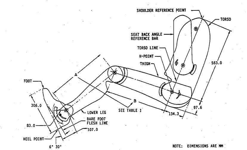
FIGURE 1—H-POINT TEMPLATE
4.3.1.3 Position the vertical reference scribe lines on the seatback angle reference bar parallel to the body grid lines on the layout drawing.
4.3.2 FRONT SEAT—DRIVER POSITION—Leg and foot positioning for any specified Accelerator Heel Point location.
4.3.2.1 Holding the torso portion of the template in position as outlined in 4.3.1.1 to 4.3.1.3, position the heel point of the template at the specified heel point location. This point on the layout is located on top of the heel pad or the depressed floor covering surface at the Y plane centerline of the accelerator pedal.
4.3.2.2 Holding the heel point at the specified location, rotate the foot forward until the Ball of the Foot contacts the undepressed accelerator pedal without infringing upon the 87 degrees minimum foot angle.
4.3.2.3 The undepressed accelerator pedal (point of contact with Ball of Foot) may be determined by locating the heel point as described previously and presetting and locking the foot angle to 87 degrees.
4.3.2.4 Draw in the template outline and pivot centers.
4.3.3 FRONT SEAT—DRIVER POSITION—Leg and foot positioning for any specified undepressed accelerator pedal location.
4.3.3.1 Holding the torso portion of the template in position as outlined in 4.3.1.1 to 4.3.1.3, position the Ball of the Foot on the specified undepressed accelerator pedal with the sole of the foot on the pedal and the heel as far forward as allowable. However, the foot angle is never less than 87 degrees. Lock foot angle quadrant.
4.3.3.2 Draw in the template outline and pivot centers.
4.3.4 FRONT SEAT—DRIVER POSITION—Leg and foot positioning for any specified leg room and SgRP-front to heel.
4.3.4.1 Holding the torso portion of the template in position, as outlined in 4.3.1.1 to 4.3.1.3, position the heel point of the template at the specified height. SgRP-front to heel, and the foot angle locked at 87 degrees.
34.3.4.2 Move the foot forward along the heel point line until the distance between the angle pivot point and the SgRP is equal to the specified leg room less 254 mm (10 in).
4.3.4.3 Draw in the template outline and pivot centers.
4.3.5 SECOND SEAT—LEFT SIDE OCCUPANT POSITION—Leg and foot positioning with the front seat in its rear-most normal driving and riding position.
4.3.5.1 Holding the torso portion of the template in position as outlined in 4.3.1.1 to 4.3.1.3 but on the SgRP second, place the foot (heel and ball) on the depressed floor covering line. The foot is to be placed on the Y plane centerline of the occupant or up to 127 mm (5 in) on either side of the Y plane centerline on the floor pan section.
NOTE—Locating the foot either side of the Y plane centerline of the occupant position will make the foot location compatible to the foot location in the existing H-Point machine installation procedure.
4.3.5.2 Move the foot forward along the depressed floor covering line to the nearest interference of the toe, instep, lower leg, or knee with the front seat. The foot angle is to be restricted to a maximum of 130 degrees.
4.3.5.3 Draw in the template outline and pivot centers.
4.3.6 THIRD SEAT—LEFT SIDE OCCUPANT POSITION—FORWARD FACING
4.3.6.1 Follow the procedure as outlined for the second seat, left side occupant position except that the template is positioned in the third seat compartment.
4.3.7 THIRD SEAT—LEFT SIDE OCCUPANT POSITION—REARWARD FACING
4.3.7.1 Follow the same procedure as outlined for the third seat—side occupant position—forward facing except that the foot is positioned in the footwell to the interference with the rear end or closure.
4.3.8 H-Point template layout using data obtained during H-Point machine installation.
4.3.8.1 Position the H-Point pivot of the template at the measured H-Point location on a layout drawing or grid system.
4.3.8.2 Follow the procedure as outlined in 4.3.1.1 to 4.3.1.3 using the measured back angle instead of the design back angle.
4.3.8.3 Holding the torso portion of the template in position as outlined previously, move the upper leg segment to measured hip angle shown on the hip angle quadrant.
4.3.8.4 Lock this quadrant in place.
4.3.8.5 Position and lock the foot angle quadrant to the measured foot angle.
4.3.8.6 Allowing the knee angle to vary as necessary, position the ankle pivot center on an arc from the hip pivot center equal to the measured effective leg room less 254 mm (10 in).
45. H-Point Machine—Description, Application, and Installation Procedure
5.1 Description—A machine (Figures 2 and 3) with back and seat pan representations of deflected seat contours of adult males. Constructed of reinforced plastic and metal, these separate back and seat pans simulate the human torso and thigh and are mechanically hinged at the H-Point. A graduated sliding probe is hinged from the H-Point to measure the headroom in the compartment. A quadrant is fastened to the probe to measure the back angle. An adjustable thigh bar, attached to the seat pan, establishes the thigh centerline and serves as a baseline for the hip angle quadrant. Lower leg segments, also adjustable in length, are connected to the seat pan assembly at the knee joining T-bar, which is a lateral extension of the adjustable thigh bar. Quadrants are incorporated in the lower leg segments to measure knee angles. Shoe and foot assemblies are calibrated to measure the angular relation to the lower leg segment. Positive stops are provided in the thigh and lower leg segments for the 10th, 50th, and 95th percentile of adult male dimensions (Table 1). Two spirit levels orient the device in space. Body segment weights are placed at the center of gravity locations to provide seat penetration equivalent to a 76 kg (167 lb) male.1
The lower leg and thigh segments are available in 10th1, 50th1, and 95th1 percentile lengths. (See Table 1).
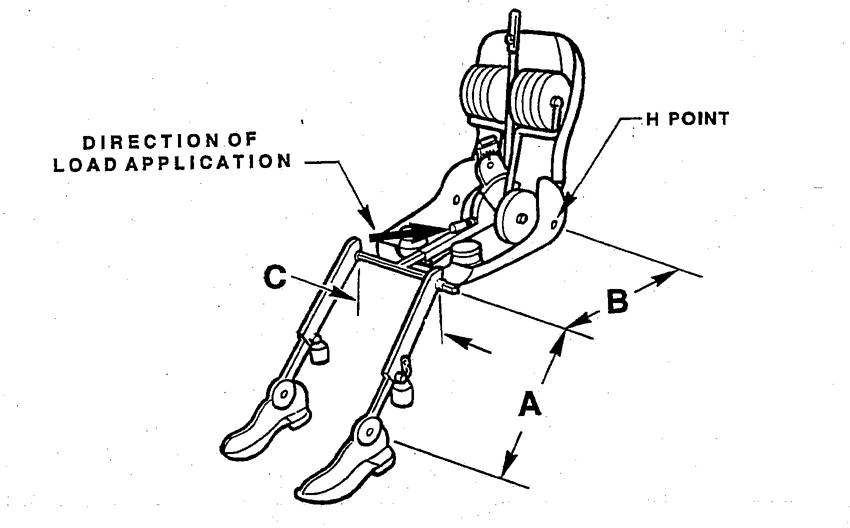
FIGURE 2—H-POINT MACHINE
1. The adult male dimensions were in part taken from the 50th percentile data as acquired by. See Geoffrey Table 1, Note 1. The remaining dimensions were developed from U.S. Department of Health, Education, and Welfare data by the Design Devices Subcommittee of the SAE Human Factors Engineering Committee, March, 1969.
5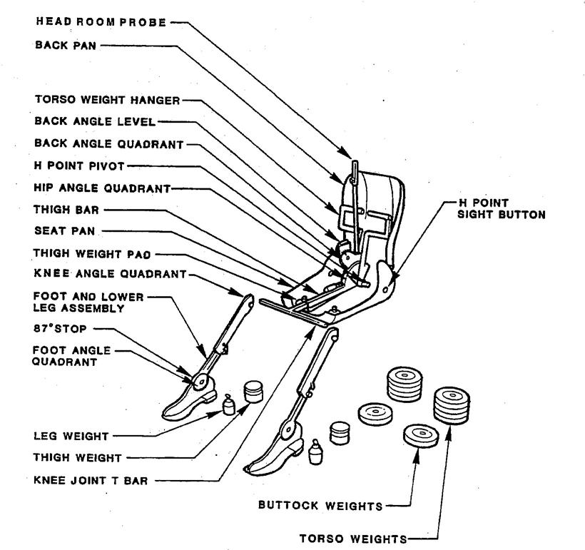
FIGURE 3—H-POINT MACHINE
| 10th Percentile(1) mm | 50th Percentile(1) mm | 95th Percentile(2) mm | |
|---|---|---|---|
| Lower leg segment (A) | 390.4 | 417.5 | 459.1 |
| Thigh segment (B) | 407.7 | 431.5 | 456.0 |
| Source | 1 | 1 | 2 |
| 1. S.P. Geoffrey, “A 2-D Manikin—The Inside Story.” Paper 267A presented at SAE Automotive Engineering Congress, Detroit, January 1961. | |||
| 2. Values for the 95th percentile leg lengths were developed on the basis of best judgment of available data by the Design Devices Subcommittee of the SAE Human Factors Engineering Committee at the July 1968 and March 1969 meetings. | |||
5.2 Application
5.2.1 Aid in the design and development of seats and seat materials.
5.2.2 Check vehicle seating compartments for conformance to design specifications, that is, relationship of H-Point to body structures, seats, controls, etc.
5.3 Installation Procedure
5.3.1 Dimensions are measured relative to the X and Z body zero planes by setting up the vehicle relative to the front and rear fiducial mark (see SAE J182a) height (H163 and H164). Curb and gross weight rating loads require different fiducial mark heights. (See SAE J1100.) All interior dimensions are measured with the front seat in the rearmost normal driving and riding position as specified by the manufacturer. When the seatback has an angular adjustment separate from the seat cushion, the normal driving or riding seatback angle is specified by the manufacturer (L40). Use 25 degrees if not specified. The tilt adjustment, if available, should be in the design position.
5.3.2 Sufficient time shall be allowed to ensure that the seat material reaches room temperature to avoid extreme temperature variations. If the seat to be checked has never been sat upon, a 68 to 79 kg (150 to 175 lb) person shall sit on the seat twice for 1 min to flex the cushion and back. All seat assemblies are to remain unloaded for a minimum period of ½h (1h preferred) prior to the H-Point machine installation.
5.3.3 Place a piece of muslin cotton cloth over the seat area to be checked. The muslin cloth should be 910 mm (36 in) square and be of a quality comparable to a grade described as a weave of 48 threads/in2 and density of 2.85 yd/lb. The muslin should be tucked in a sufficient amount to prevent hammocking of the material. If the test is run in a buck, suitable floor covering sections, or equivalent, are to be placed under the H-Point machine's feet.
5.3.4 Place seat and back assembly of the H-Point machine at the centerline of occupant (C/LO). C/LO is also the centerline of H-Point machine and is 381 mm (15 in) outboard from the vehicle centerline on the driver's side, unless otherwise specified by the manufacturer. The C/LO is moved inboard from the 381 mm (15 in) line when the H-Point machine is sitting far enough outboard that the seat edge will not permit leveling of the H-Point machine. It is moved inboard the necessary distance to permit leveling of the H-Point machine and the new dimension from centerline of vehicle to C/LO noted in recording measurements. In vehicles with bucket front seats or Individual auxiliary seats, the centerline of the seat is the basis for interior dimensions relating to these seats.
5.3.5 Use 95th percentile leg and thigh segments specified in Table 1.
5.3.6 Attach foot and lower leg assemblies to the seat pan assembly, either individually at the knee joint or by using the T-bar lateral segment and lower leg assembly.
The T-bar lateral segment should be parallel to the ground and perpendicular to the Y plane of the vehicle unless otherwise specified by the manufacturer.
5.3.7 The feet and leg positions of the H-Point machine for the various individual seat positions to be checked are as follows:
75.3.7.1 Front Seat—Driver Position—The right foot and leg assembly is placed on the undepressed (blocked or mechanically restrained) accelerator pedal with the sole of the foot on the pedal and the heel as far forward as allowable. The right leg is adjusted inboard on the T-bar toward the centerline of the vehicle until just contacting the tunnel (or other components) or until the Ball of Foot on the shoe is aligned with the center of the accelerator pedal pad unless specified otherwise by the manufacturer. Tunnel contact at the heel is defined where the Heel Point on the foot is at the beginning transition of horizontal to upturned compressed carpet surface. The heel may not be placed on the toe board. However, the foot angle is never less than 87 degrees. The 87 degree limit can be fixed by inserting the pin into the foot assembly.
The left foot is positioned on the floor or toe pan and located approximately the same distance to the left of the H–Point machine centerline as the right foot is to the right. The T–bar should be maintained parallel to the ground.
5.3.7.2 Front Seat—Occupant in Vehicle Centerline Position—The H-Point machine is installed in the front seat vehicle centerline position with both legs extended at the specified percentile, one on either side of the tunnel. The left foot is placed on the undepressed accelerator pedal and the right foot is located to the right of the tunnel, approximately opposite and symmetrical in a manner that levels the knee joint T-bar. A T-bar extension may be required to straddle the knee segments on either side of the tunnel. In vehicles having no tunnel, the feet are set approximately 254 mm (10 in) apart. The leg comfort angles are determined from the H-Point machine's left leg.
5.3.7.3 Second Seat—Side Occupant Position—The H-Point machine is installed in the second seat outboard occupant position 381 mm (15 in) outboard from the vehicle centerline, unless otherwise specified by the manufacturer. (Check applicable seating arrangement drawing for specified location) The two feet are placed together and positioned to the nearest interference of the toe, instep, or lower leg with the front seat, unless otherwise specified by the manufacturer. In instances where one foot reaches interference before the other, the one with the nearest interference will be used for dimensioning purposes. For additional H–Point machine leg location conditions and restrictions, see Section 6 and Section 7 for H–Point machine installation in long– and short–coupled vehicles.
5.3.7.4 Second Seat—Occupant in Vehicle Centerline Position—The H–Point machine is installed in the second seat-vehicle centerline position with both the foot and lower leg assemblies placed astride the tunnel on the normal floor. Both leg assemblies are extended to the nearest interference of the toe, instep, or lower leg with the front seat.
If necessary, in order to clear lateral obstructions, such as seat belt anchors, tunnel width, etc., the T-bar may be extended. In vehicles with no tunnel, set the H-Point machine's feet approximately 254 mm (10 in) apart.
5.3.8 Apply lower leg and thigh weights and level the H-Point machine.
5.3.9 Tilt the back pan forward against the forward stop and draw the H-Point machine away from the seatback using the T-bar. Reposition the H-Point machine on the seat by one of the following methods:
5.3.9.1 If the H-Point machine tends to slide rearward, use the following procedure: Allow the H-Point machine to slide rearward until a forward horizontal restraining load on the T-bar is no longer required due to the seat pan contacting the seatback.
5.3.9.2 If the H-Point machine does not tend to slide rearward, use the following procedure: Slide the H-Point machine rearward by a horizontal rearward load applied at the T-bar until the seat pan contacts the seatback.
85.3.10 Apply a 10 kg (22 lb) load twice to the back and pan assembly positioned at the intersection of the hip angle quadrant and the T-bar housing (Figure 2). The direction of load application should be maintained along a line from the above intersection to a point just above the thigh bar housing. Then carefully return the back pan to the seatback. Care must be exercised through the remainder of the procedure to prevent the H-Point machine from sliding forward.
5.3.11 Install the right and left buttock weights and then alternately the eight torso weights. Maintain H-Point machine level.
5.3.12 Tilt the back pan forward until the stop is contacted. Rock the H-Point machine from side to side over a 10 degree are (5 degrees to each side of the vertical centerline) for three complete cycles to release any accumulated friction between the H-Point machine and the seat. During the rocking, the T-bar of the H-Point machine may tend to change from the specified horizontal and vertical alignment; therefore, the T-bar must be restrained and properly aligned by applying an appropriate lateral load during the rocking motions. Care shall be exercised in holding the T-bar and rocking the H-Point machine to minimize inadvertent exterior loads applied in a vertical or fore-and-aft direction. The H-Point machine's feet are not to be restrained or held during this step, and if the feet change position, they should be allowed to remain in that attitude at this time. Due to the movement of the feet during the H-Point machine rocking operation, the feet are repositioned as follows:
If the seat pan is not level at the completion of this step, apply a sufficient lateral load to the seatback pan to level the H-Pont machine seat pan on the seat.
5.3.13 Holding the T-bar to prevent the H-Point machine from sliding forward on the seat cushion, proceed as follows:
Alternately apply and release this force until the hip angle readout indicates that the back pan has reached a stable position after the applied force has been released, that is, repeated identical hip angle readouts. Care shall be exercised to minimize exterior downward or side forces applied to the H-Point machine. If an H-Point machine level adjustment is necessary, rotate the back pan forward, relevel, and repeat the H-Point machine back rocking.
5.3.14 If a return of the H-Point machine installation is desired, the seat assembly should remain unloaded for a minimum period of ½h prior to the rerun. The loaded H-Point machine should not be left on the assembly longer than the time required to perform the test.
96. Second Seat Installation Procedure for Short-Coupled Vehicles—If the H-Point couple distance is such that the H-Point machine with 95th percentile leg will not fit into the second seat with the front seat in the rearmost normal driving and riding position (that is, the leg interferes with the front seatback), install the machine in the second seat in accordance with either of the methods (A or B) shown in Appendix A.
7. H-Point Machine Second Seat Installation for Long-Coupled Vehicles—In large vehicles where the ankle or foot does not normally touch the nearest interference with the front seat, the sole of the H-Point machine's foot is placed on the foot support and the heel is located as indicated on the seating arrangement drawing. All angles are measured with the H-Point machine in this position. If foot support does not exist, extend the H-Point machine legs to the full limit of the seat deflection with both feet flat on the floor. The foot angle should not exceed 130 degrees.
8. Determination of Cushion Angle—A measure called Cushion Angle has been developed to determine the attitude that a seat cushion imposes on the seated occupant's thighs independent of seating package geometry. This measure uses the H-Point machine with lower legs removed and the torso weights redistributed about the seat pan.
Normally, the H-Point machine thigh attitude depends on the seating package arrangement because the machine's foot location in the package sets the angle of the lower leg and thigh. Much like the Torso Angle reflects the torso attitude imposed by the seat back on the three-dimensional H-Point machine. Neither Torso Angle or Cushion Angle depend on the particular seating package geometry.
The Cushion Angle measurement procedure is presented in Appendix B.
9. H–Point Machine and Template Fabrication—Fabrication of the H-Point machine and the H-Point template must conform to design as specified in the Society of Automotive Engineers Standard SAE J826 specifications.
9.1 Each H-Point machine must have a permanently attached identification plate showing the following information:
Three-Dimension H-Point Machine
No.___________________
This measuring devices is constructed in full accordance with the Society of Automotive Engineers Standard SAE J826 specifications.
9.2 Three H–Points template leg segments are available duplicating 10th, 50th, and 95th percentile leg lengths of the H-Point machine.
10. Notes
10.1 Marginal Indicia—The change bar (1) located in the left margin is for the convenience of the user in locating areas where technical revisions have been made to the previous issue of the report. An (R) symbol to the document title indicates a complete revision of the report.
PREPARED BY THE SAE HUMAN ACCOMODATION AND DESIGN DEVICES STANDARDS COMMITTEE
10A.1 Either Method A or B may be used to install the H-Point machine in the second seat of short-coupled vehicles. These procedures are both currently in use, and while they will not necessarily produce the same seating dimensions, there is no strong technical basis that exists thus far to favor one method over the other.
A.1.1 Method A
A.1.2 Method B
B.1 Background and Definition of Cushion Angle—See 2.2.8 Cushion Angle, Section 7 Determination of Cushion Angle and SAE J1100.
B.2 Measurement Procedure—Cushion Angle is measured using the H-Point machine with torso weights redistributed and lower legs removed to eliminate any confounding effect of packaging geometry on thigh attitude. Figure B1 for distribution of weights.
B.2.1 Follow the same installation procedures as described in 4.3.1 through 4.3.4 but with both lower legs removed.
B.2.2 Place the seat and back assembly with legs removed on the selected seat. Lateral location for the driver is specified in 4.3.4. Other seated positions are specified in 4.3.7.2 through 4.3.7.4.
B.2.3 Alternately install the two buttock weights on the hip point pivot on the seat pan. Alternately place two torso weights next to the buttock weights.
B.2.4 Install the two thigh weights on the seat pan and level the machine.
B.2.5 Apply a 35 lb load to the push spring on the machine seat pan.
B.2.6 Add, alternately, four additional torso weights next to the hip point pivot. (All weights are placed on or in the seat pan.)
B.2.7 Add, alternately, the remaining two torso weights at the front of the seat pan. The weights will each lay propped outwardly in the forward corner of the seat pan against the thigh weights.
B.2.8 Set the back angle quadrant to zero, rotate the head room probe to vertical using the back angle level and lock it in position. The machine is now prepared for Cushion Angle readout using the hip angle quadrant to measure the Thigh Centerline angle (Hip angle relative to a vertical Back angle).
12(Cushion Angle) = (90 Degrees − Hip Angle)
FIGURE B1—DISTRIBUTION OF WEIGHTS FOR CUSHION ANGLE MEASUREMENT
13Rationale—Not applicable.
Relationship of SAE Standard to ISO Standard—Not applicable.
Application—The devices of this SAE Standard provide the means by which passenger compartment dimensions can be obtained using a deflected seat rather than a free seat contour as a reference for defining seating space. All definitions and dimensions used in conjunction with this document are described in SAE J1100. The devices described in this document are intended for applications concerning seated driver side or center occupant accommodation spaces only and are not to be construed as instruments which measure or indicate occupant capabilities or comfort. This document covers only one H-Point machine installed on a seat during each test. Certified H-Point templates and machines can be purchased from:
Society of Automotive Engineers, Inc.
400 Commonwealth Drive
Warrendale, PA 15096-0001
Reference Section
SAE J182—Motor Vehicle Fiducial Marks
SAE J1100—Motor Vehicle Dimensions
S. P. Geoffrey, “A 2-D Manikin—The Inside Story.” Paper 267A presented at SAE Automotive Engineering Congress, Detroit, January 1961.
Developed by the SAE Human Accommodation and Design Devices Standards Committee
14 15 16