
In order to promote public education and public safety, equal justice for all, a better informed citizenry, the rule of law, world trade and world peace, this legal document is hereby made available on a noncommercial basis, as it is the right of all humans to know and speak the laws that govern them.
SAE Standard
Last Revised October 1980
S. A. E.
LIBRARY
THIS IS A PREPRINT WHICH IS
SUBJECT TO REVISIONS AND
CORRECTIONS. THE FINAL
VERSION WILL APPEAR IN THE
1982 EDITION OF THE SAE
HANDBOOK.
The φ symbol is for the convenience of the user in locating areas where technical revisions have been made to the previous issue of the report. If the symbol is next to the report title, it indicates a complete revision of the report.
Copyright © 1981 Society of Automotive Engineers, Inc.
CHEADLAMP AIMING DEVICE FOR MECHANICALLY AIMABLE SEALED BEAM HEADLAMP UNITS—SAE J602 OCT80
SAE Standard
Report of the Lighting Committee, approved October 1957, last revised October 1980.
1. Scope–This specification applies to the requirements of a device used in the field and inspection stations to aim the mechanically aimable type of scaled beam hadelamp units.
The purpose of this specification is to provide a laboratory test procedure to determine whether the devices under test are capable of accurately positioning scaled beam headlamp units from their aiming pads and maintaining their accuracy in service within the tolerances designated in this specification.
2. Definitions
2.1 Headlamp Aiming Device–A device used to adjust and inspect the aim of mechanically aimable headlamp units consisting of one or more fixtures designed to seat against the three aiming pads (aiming plane) on mechanically aimable headlamp units installed on a vehicle to facilitate accurate aiming of such units, vertically and laterally.
2.2 Mechanically Aimable Headlamp Units–A unit having three pads on the face of the lens forming a mechanical aiming plane used to adjust and inspect the aim of the unit when installed on a vehicle.
2.3 Aiming Plane–A plane through the three aiming pads on the face of the lens.
3. Samples for Test–Sample devices submitted for laboratory tests shall be representative of the devices as regularly manufactured and marketed. Each sample shall include all accessory equipment peculiar to the device. Full assembly and operating instructions shall be provided, including information on how to check accuracy and maintain the device in calibration.
4. Laboratory Facilities–The laboratory shall be equipped with all facilities necessary to make the tests required in this standard.
5. General Requirements
5.1 The device shall be of such design that the seating portion will register only on the three aiming pads on the sealed beam units as covered by SAE J571.
5.2 No part of the device, except those parts (strings, sighting devices, scales, etc.) required for referencing lateral alignment between devices, shall extend beyond the dimensional limits of the headlamp aiming device locating plate (Fig. 1, dimension C; Fig. 2, 4.05 in (102.9 mm) maximum diameter dimension; and Fig. 3, 4.05 in (102.9 mm) maximum diameter dimension).
5.3 A device which uses adapters to fit more than one size sealed beam unit shall meet all of the requirements of this recommended practice with and without adapters.
5.4 The seating plane of the device shall meet the dimensions shown in Fig. 1, Fig. 2, or Fig. 3.
5.5 When aiming headlamp units spaced 90 in (2300 mm) apart, the torque exerted by the device at the aiming plane shall not exceed 18 lbf-in (2.0 N-m) vertically and 12 lbf-in (1.4 N-m) laterally.
5.6 The means of securing the device to the sealed beam unit shall retain the device against the three aiming pads when an axially centered tensile force of 4.0 lbf (17.8 N) minimum is applied to the device.
5.7 The device shall be capable of being calibrated and shall have available
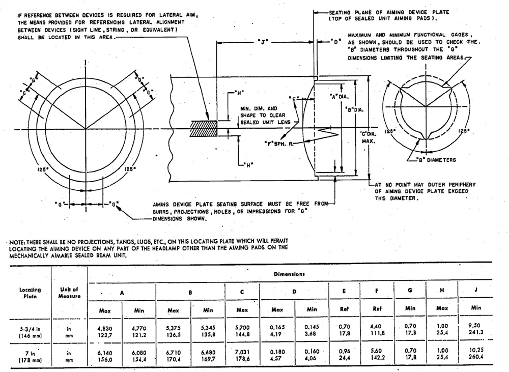
FIG 1—DIMENSIONAL SPECIFICATIONS FOR HEADLAMP AIMING DEVICE LOCATING PLATE
1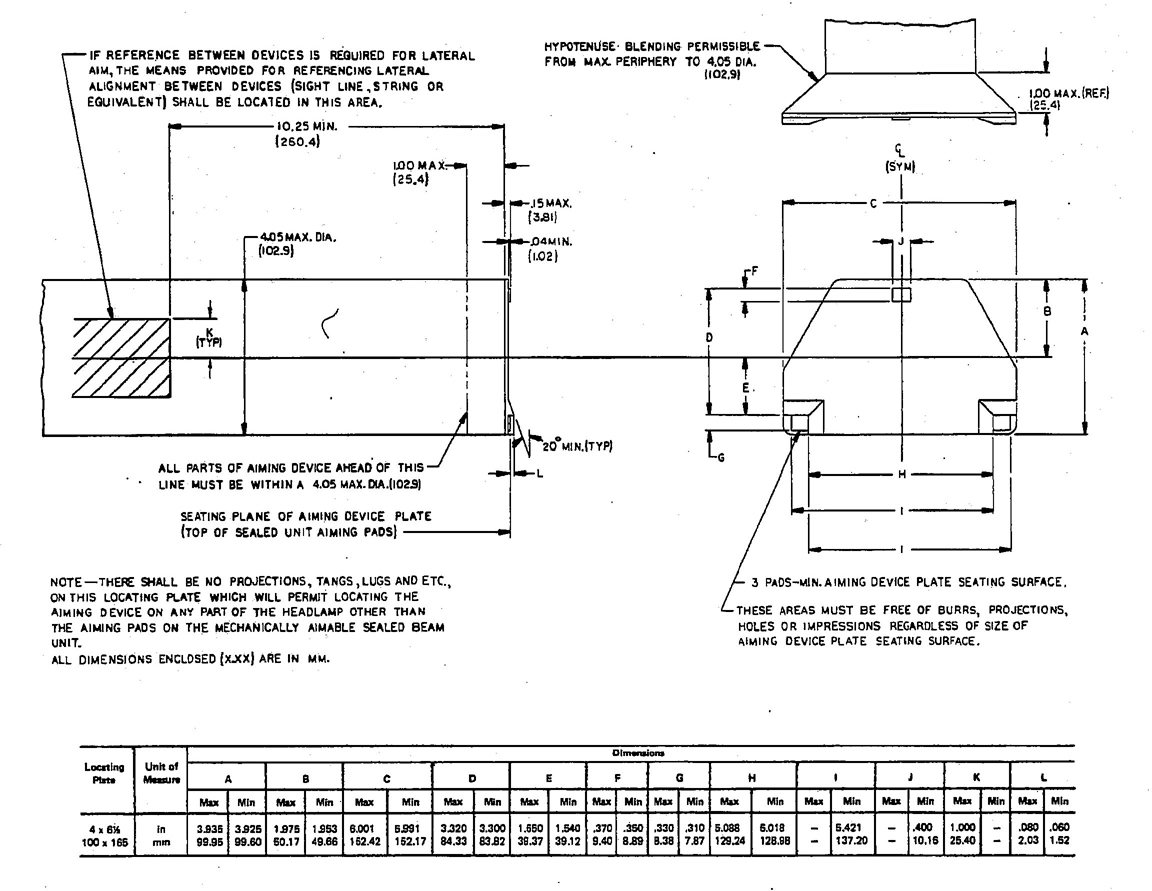
φ FIG. 2—DIMENSIONAL SPECIFICATIONS FOR HEADLAMP AIMING DEVICE LOCATING PLATE (100 × 165)
for immediate use an independent calibration fixture and/or instructions to immediately recalibrate the device.
φ 5.8 If a suction cup is used to retain the device to the headlamp unit, the effective diameter for 5¾ in (146 mm) and 7 in (178 mm) shall not exceed 3.5 in (90 mm) and the effective diameter for 4 × 6½ in (100 × 165 mm) and 5 × 8 in (142 × 200 mm) shall not exceed 2.8 in (71 mm) when installed.
5.9 Means shall be provided in the device for compensating within ±0.1 deg through a slope range of ±1.5 deg from horizontal. The method for device compensation shall be clearly explained in the operating instructions.
φ 5.10 If the lateral aim is to be accomplished by reference between devices on opposite sides of the vehicle, the means provided for referencing lateral alignment between devices (sight line, string, or equivalent) shall be located as shown in Fig. 1, Fig. 2, and Fig. 3.
5.11 The spirit level or other means provided for indicating vertical aim shall be capable of showing at least a 0.1 in (2.5 mm) deviation with a 1 in (25 mm)1 change in level.
5.12 A lateral aim scale shall be provided with graduations in steps of not more than 2 in (51 mm)1 from straight ahead to at least 8 in (203 mm)1 left and right.
5.13 The instructions covering use of the device shall include those items shown in Section 3 of SAE J599.
5.14 The vertical aim scale shall be marked O with the aiming plane vertical.
5.15 The vertical aim scale shall be provided with numerical graduations in steps, each of which represents 1 in (25 mm)1 to provide for variations in vertical aim from at least 8 in (203 mm)1 above O to 8 in (203 mm)1 below O.
6. Test Procedure—Assuming that the devices comply with the general requirements, they shall be considered acceptable if they comply with additional test requirements as follows:
Note 1—All tests are to be made in an ambient temperature of 75 ± 5°F (24 ± 3°C) unless otherwise specified.
Note 2—If a vertical indication means other than a spirit level is used, an equivalent accuracy shall be maintained.
6.1 With the aiming plane vertical and with the vertical scale on the device set at O, the angle through which the aiming plane must be rotated vertically to center the bubble in the spirit level, or equivalent, shall not exceed 0.5 in (13 mm)1.
6.2 With the aiming planes in the same vertical plane and with the means provided for adjusting lateral aim in use, the angle through which the aiming plane must be rotated laterally to indicate straight ahead shall not exceed ±1 in (25 mm)1 with the lamps 24 and 90 in (610 and 2300 mm) apart.
6.3 With the aiming planes initially in the same vertical plane and subsequently
2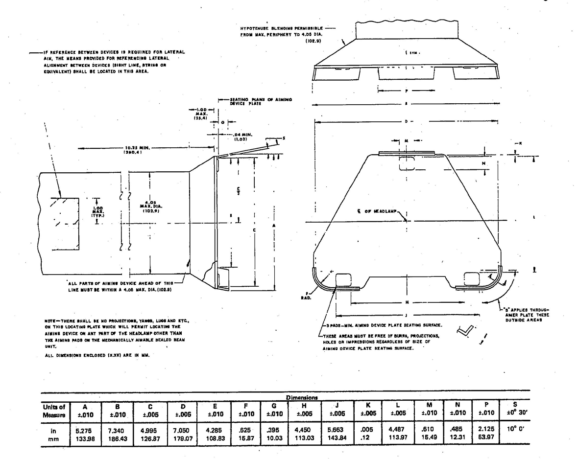
φ FIG. 3—DIMENSIONAL SPECIFICATIONS FOR HEADLAMP AIMING DEVICE LOCATING PLATE (142 × 200)
toed inward and outward 6 in (152 mm)1 and with the means provided for checking lateral aim in use, the error in reading shall not exceed ±1 in (25 mm)1 with the lamps 60 in (1520 mm) apart.
6.4 With the aiming plane vertical and with the vertical scale on the device set at O, the level on the aimer shall be adjusted prior to each of the following tests to center the bubble in the spirit level or equivalent.
6.4.1 Each step on the vertical aim scale shall be checked and in no case shall the variation from correct aim exceed ±0.5 in (13 mm).1
6.4.2 A pair of devices shall be stabilized at 20 ± 5°F (−7 ± 3°C) and then installed on a pair of unlighted sealed beam units spaced 60 in (1520 mm) apart at the 20°F (−7° C) ambient temperature. After a period of 30 min, the seating portion of the device shall continue to register against the three sealed beam unit aiming pads, and the variation from correct lateral aim shall not exceed ±0.5 in (13 mm)1 and the variation from correct lateral aim shall not exceed ±1 in (25 mm).1
6.4.3 A pair of aiming devices shall be stabilized at 100 ± 5°F (38 ± 3°C) and then installed on a pair of lighted sealed beam units spaced 60 in (1520 mm) apart at the 100°F (38°C) ambient temperature. After a period of 30 min, the seating portion of the device shall continue to register against the three sealed beam unit aiming pads and the variation from correct vertical aim shall not exceed 0.5 in (13 mm)1 and the variation from correct lateral aim shall not exceed ±1 in (25 mm).1
6.4.4 A pair of devices shall be exposed with the aiming plane down in a circulating air over to 140 ± 5°F (60 ± 3°C) for 24h followed by a temperature of −40 ± 5°F (−40 ± 3°C) for 24h and then permitted to return to room temperature, after which they shall show no visible damage. They shall then be installed on the pair of unlighted sealed beam units spaced 60 in (1520 mm) apart and the variation from correct lateral aim shall not exceed ±1 in (25 mm).
6.4.5 A sample device shall be exposed to 35 ± 5°F (1.7 ± 3°C) for 1h and then immediately allowed to free fall onto a concrete floor three times from its normal operating position on a sealed beam unit at a height of 40 in (1020 mm), after which it shall show no damage that would interfere with the proper recalibration of the device. It shall then be installed in combination with its companion device on a pair of unlighted sealed beam units spaced 60 in (1520 mm) apart and the variation from correct vertical aim shall not exceed 1 in (25 mm)1 and the variation from correct lateral aim shall not exceed 1 in (25 mm).1 (This test applies only to devices which are supported by the sealed beam unit.)
6.5 Using the calibration fixture and/or instructions required by paragraph 5.7, the device shall be calibrated and checked for compliance with paragraphs 6.1 and 6.2.
1 Represents inches (millimeters) at 25 ft (7.6 m).
3All technical reports, including standards approved and practices recommended, are advisory only. Their use by anyone engaged in industry or trade or their use by governmental agencies is entirely voluntary. There is no agreement to adhere to any SAE Standard or Recommended Practice, and no commitment to conform to or be guided by any technical report. In formulating and approving technical reports, the Technical Board, its councils, and committees will not investigate or consider patents which may apply to the subject matter. Prospective users of the report are responsible for protecting themselves against liability for infringement of patents, trademarks, and copyrights.
PRINTED IN U.S.A.
4 5 6