In order to promote public education and public safety, equal justice for all, a better informed citizenry, the rule of law, world trade and world peace, this legal document is hereby made available on a noncommercial basis, as it is the right of all humans to know and speak the laws that govern them.
S. A. E.
LIBRARY
SAE Standard
Completely revised January 1977
THIS IS A PREPRINT AND WILL
APPEAR IN THE NEXT EDITION
OF THE SAE HANDBOOK
Copyright © Society of Automotive Engineers, Inc. 1977
All rights reserved.
φ REFLEX REFLECTORS—SAE J594f
SAE Standard
Report of Lighting Committee approved July 1971 and completely revised January 1977.
1. Scope—This SAE Standard is an engineering design standard for reflex reflectors. This design standard is intended to be supplemented by an SAE service performance standard for reflex reflectors which is under development.
2. Definition—Reflex reflectors, for the purpose of this specification, include only devices which are used on vehicles to give an indication to an approaching driver by reflected light from the lamps on the approaching vehicle.
3. Requirements
3.1 General—The following sections from SAE J575 are a part of this standard:
3.1.1 Section B—Samples for Test
3.1.2 Section D—Laboratory Facilities
3.1.3 Section E—Vibration Test
3.1.4 Section F—Moisture Test–Except that in the case of sealed units there shall be no visible moisture within the unit.
3.1.5 Section G—Dust Test
3.1.6 Section H—Corrosion Test
3.1.7 Section J—Photometry–The reflex reflector shall be set up for testing as shown in Fig. 1. The test distance shall be 100 ft (30.5 m). The source of illumination shall be a lamp with a 2 in (50 mm) effective diameter and with a filament operating at 2856 K color temperature. The observation point shall be located directly above the source of illumination. The reflex reflector shall be mounted on a goniometer with the center of the reflex area at the center of rotation and at the same horizontal level as the source of illumination. The H–V axis of reflex reflectors shall be taken as parallel to the longitudinal axis of the vehicle for rear reflectors and perpendicular to a vertical plane passing through the longitudinal axis of the vehicle for side reflectors.
Photometric measurements of reflex reflectors shall be made at various observation angles and entrance angles as shown in Table 1. The observation angle is the angle formed by a line from the observation point to the center of the reflector and a second line from center of the reflector to the source of illumination. The entrance angle is the angle between the axis of the reflex reflector and a line from the center of the reflector to the source of illumination. The entrance angle shall be designated left, right, up, and down in accordance with the position of the source of illumination with respect to the axis of the reflex reflector as viewed from behind the reflector.
Photometric measurements shall be made photoelectrically, and the candlepower which the reflex reflector is projecting toward the observation point shall be determined. Also, the illumination on the reflex reflector from the source of illumination shall be measured in footcandles. The recorded measurement of each test point is the quotient of the projected candlepower divided by the footcandle illumination. Reflex reflectors may have any linear or area dimensions; but, for the photometric test a maximum projected area of 12 in2 (7740 mm2) contained within a 10 in (254 mm) diameter circle shall be exposed.
In making photoelectric measurements, the opening to the photocell shall not be more than 0.5 in (13 mm) vertical by 1 in (25 mm) horizontal with the observation point above the source of illumination.
Reflex reflectors, which do not have a fixed rotational position on the vehicle, shall be rotated about their axis through 360 deg to find the minimum candlepower per footcandle which shall be reported for each test point. If the output falls below the minimum requirement at any test point, the reflector shall be rotated ± 5 deg about its axis from the angle where the minimum output occurred; and the maximum candlepower per footcandle within this angle shall be reported as a tolerance value.
Reflex reflectors, which, by their design or construction, permit mounting on the vehicle in fixed rotational position, shall be tested in this position. A visual locator, such as the word TOP shall not be considered adequate to establish a fixed rotational position on the vehicle.
If uncolored reflections from the front surface interfere with photometric readings at any test point, the operator shall check 1 deg above, below, right, and left of the test point, and report the lowest reading and location. The latter must meet the minimum requirements for the test point.
3.1.8 Color—Section I—Color Test—The test sample may be either the reflex reflector or a disc of the same material, technique of fabrication, and dye formulation as the reflex reflector. If a disc is used, the thickness should be twice the thickness of the reflector as measured from the face of the lens to the apexes of the reflecting elements.
3.2 Plastic Material Test—See SAE J576
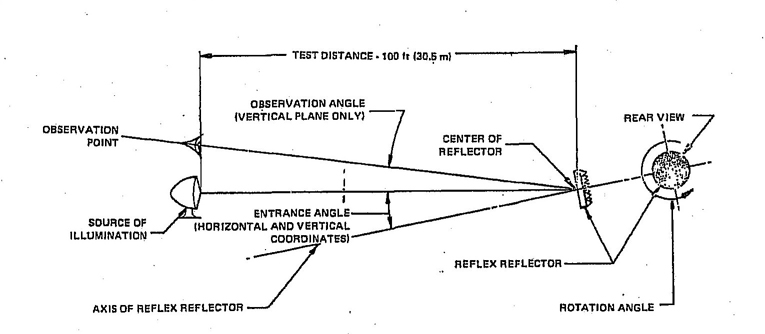
FIG. 1—SETUP FOR TESTING
4| Observation Angle (degrees) |
Entrance Angle (degrees) | ||||
|---|---|---|---|---|---|
| 0 deg | 10 deg Up | 10 deg Down | 20 deg Left | 20 deg Right | |
| 0.2 | 420 | 280 | 280 | 140 | 140 |
| 1.5 | 6 | 5 | 5 | 3 | 3 |
| aYellow values shall be 2.5 times indicated red values and white values shall be 4 times indicated red values. | |||||
| Observation Angle (degrees) |
Entrance Angle (degrees) | ||||
|---|---|---|---|---|---|
| 0 deg | 10 deg Up | 10 deg Down | 20 deg Left | 20 deg Right | |
| 0.2 | 4.5 | 3.0 | 3.0 | 1.5 | 1.5 |
| 1.5 | 0.07 | 0.05 | 0.05 | 0.03 | 0.03 |
| aYellow values shall be 2.5 times indicated red values and white values shall be 4 times indicated red values. | |||||
SAE Technical Board Rules and Regulations
All technical reports, including standards approved and practices recommended, are advisory only. Their use by anyone engaged in industry or trade is entirely voluntary. There is no agreement to adhere to any SAE Standard or SAE Recommended Practice, and no commitment to conform to or be guided by any technical report.
In formulating and approving technical reports, the Technical Board, its Councils and Committees will not investigate or consider patents which may apply to the subject matter, Prospective users of the report are responsible for protecting themselves against liability for infringement of patents.
Printed in U.S.A.
5