In order to promote public education and public safety, equal justice for all, a better informed citizenry, the rule of law, world trade and world peace, this legal document is hereby made available on a noncommercial basis, as it is the right of all humans to know and speak the laws that govern them.
SURFACE VEHICLE STANDARD
Submitted for recognition as an American National Standard
 J578 REV. JUN95
Issued 1942-01
Revised 1995-06
Superseding J578 MAY88
1. Scope— This SAE Standard defines and provides a means for the control of colors employed in motor vehicle external lighting equipment, including lamps and reflex reflectors. The document applies to the overall effective color of light emitted by the device in any given direction and not to the color of the light from a small area of the lens. It does not apply to pilot, indicator, or tell-tale lights.
2. References
2.1 Applicable Publications—The following publications form a part of this specification to the extent specified herein. The latest issue of SAE publications shall apply.
2.1.1 SAE PUBLICATIONS—Available from SAE, 400 Commonwealth Drive, Warrendale, PA 15096-0001.
SAE J578—Color Specification for Electric Signal Lighting Devices
SAE J774—Emergency Warning Device
SAE J943—Slow-Moving Vehicle Identification Emblem
SAE HS 34—SAE Ground Vehicle Lighting Standards Manual
2.1.2 FEDERAL PUBLICATIONS—Available from the Superintendent of Documents, U.S. Government Printing Office, Washington, DC 20402-9371.
FMVSS No. 125—Warning Devices, 39 FR 28636, Aug. 9, 1974 as amended at 40 FR 4, Jan, 2, 1975 FMCSS 108
2.1.3 ASTM PUBLICATION—Available from ASTM, 100 Barr Harbor Drive, West Conshohocken, PA 19428-2959.
ASTM E 308-66—Method for Computing the Colors of Objects by Using the CIE System
3. Definitions
3.1 Chromaticity Coordinates—The fundamental requirements for color are expressed as chromaticity coordinates according to the CIE (1931) standard colorimetric system (see Figure 1). The following requirements shall apply when measured by the tristimulus or spectrophotometric methods.
SAE Technical Standards Board Rules provide that: “This report is published by SAE to advance the state of technical and engineering sciences. The use of this report is entirely voluntary, and its applicability and suitability for any particular use, including any patent infringements arising there from, is the sole responsibility of the user.”
SAE reviews each technical report at least every five years at which time it may be reaffirmed, revised, or cancelled, SAE invites your written comments and suggestions.
QUESTIONS REGARDING THIS DOCUMENT: (412) 772-8512 FAX: (412) 776-0243
TO PLACE A DOCUMENT ORDER; (412) 776-4970 FAX: (412) 776-0790
SAE WEB ADDRESS http://www.sae.org
Copyright 1995 Society of Automotive Engineers, inc.
All rights reserved.
Printed in U.S.A.
1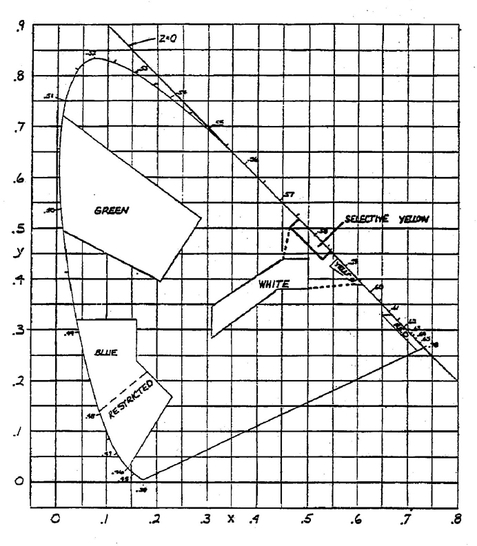
FIGURE 1—CHROMATICITY DIAGRAM
3.1.1 RED—The color of light emitted from the device shall fall within the following boundaries:
y = 0.33 (yellow boundary)
y = 0.98 − x (purple boundary)
3.1.2 YELLOW AMBER—The color of light emitted from the device shall fall within the following boundaries:
y = 0.39 (red boundary)
y = 0.79 − 0.67x (white boundary)
y = x − 0.12 (green boundary)
3.1.2.1 Selective Yellow (See A-2 Appendix)—The color of light emitted from the device shall fall within the following boundaries:
2y = 0.58x + 0.14 (red boundary)
y = 1.29x − 0.10 (green boundary)
y = 0.97 − x (white boundary)
3.1.3 WHITE (ACHROMATIC)—The color of light emitted from the device shall fall within the following boundaries:
x = 0.31 (blue boundary)
x = 0.50 (yellow boundary)
y = 0.15 + 0.64x (green boundary)
y = 0.05 + 0.75x (purple boundary)
y = 0.44 (green boundary)
y = 0.38 (red boundary)
3.1.3.1 White to Yellow—The color of light emitted from the device shall fall within one of the following areas:
3.1.4 GREEN—The color of light emitted from the device shall fall within the following boundaries:
y = 0.73 − 0.73x (yellow boundary)
x = 0.63y − 0.04 (white boundary)
y = 0.50 − 0.50x (blue boundary)
3.1.5 BLUE—This color of light emitted from the device shall fall within the following boundries:
3.1.5.1 Restricted Blue—This color should be elected when recognition of blue as such is necessary.
y = 0.07 + 0.81x (green boundary)
x = 0.40 − y (white boundary)
x = 0.13 + 0.60y (violet boundary)
3.1.5.2 Signal Blue—This color may be elected when, due to other factors, it is not always necessary to identify blue as such.
y = 0.32 (green boundary)
x = 0.16 (white boundary)
x = 0.40 − y (white boundary)
x = 0.13 + 0.60 (violet boundary)
3.2 Visual Method—When checking by the visual method of 4.1.1 the following subjective guidelines shall be considered:
3.2.1 RED—Red shall not be acceptable if it is less saturated (paler), yellower, or bluer than the limit standards.
3.2.2 YELLOW (AMBER)—Yellow shall not be acceptable if it is less saturated (paler), greener, or redder than the limit standards.
3.2.3 WHITE—White shall not be acceptable if its color differs significantly from that of a blackbody source operating at a color temperature between CIE Illuminant A (2854k) and CIE Illuminant B (5000K).
3.2.4 GREEN—Green shall not be acceptable if it is less saturated (paler), yellower, or bluer than the limit standards.
3.2.5 BLUE—Blue shall not be acceptable if it is less saturated (paler), greener, or redder than the limit standards.
34. Test Methods
4.1 Method of Color Measurement—One of the methods listed in 4.1.1, 4.1.2 or 4.1.3 shall be used to check the color of the light from the device or its optical components for compliance with the color specifications. The device shall be operated at the design test voltage. Components (bulbs, cap lenses, and the like) shall be tested in a fixture or in manner simulating the intended application.
In measuring the color of reflex devices, precautions shall be made to eliminate the first surface reflections of the incident light.
Lighting devices that are covered with neutral density filters shall be tested for color with such filters in place.
4.1.1 VISUAL METHOD—In this method, the color of the emitted light from the device is visually compared to the light from a filter/source combination are known chromaticity coordinates. The filter/source combinations are generally chosen to describe the limits of chromaticity coordinates of the color being measured. The color of the filter/source combination is determined spectrophotometrically.
In making visual appraisals, the light from the device lights one portion of a comparator field and the filter/source standard lights an adjacent area. The two fields should be in close proximity to each other.
To make valid visual comparisons, the two fields to be viewed must be of near equal luminance (photometric brightness). A means of mechanically adjusting the filter/source standard is generally used to accomplish this. See Appendix A for measuring precautions.
4.1.2 TRISTIMULUS METHOD—In this method, photoelectric detectors with spectral responses that approximate the 1931 C. E standard spectral tristimulus values are used to make the color measurements. These measured tristimulus values are used to calculate the chromaticity coordinates of the color of emitted light from the device. The instrument used for this type of measurement is a colorimeter. These instruments are generally used for production control of color and are satisfactory if calibrated against color filters of known chromaticity coordinates.
Visual tristimulus colorimeters can also be used for color evaluation. See Appendix A for measuring precautions.
4.1.3 SPECTROPHOTOMETRIC METHOD—The standard CIE method of color measurements is computing chromaticity coordinates from the spectral energy distribution of the device. This method should be used as a referee approach when the commonly used methods produce questionable results.
Refer to ASTM E 308-66 for more details on spectrophotometric measurements (reprinted in the SAE Lighting Manual, HS-34).
5. Notes
5.1 Marginal Indicia—The changer bar (1) located in the left margin is for the convenience of the user in locating areas where technical revisions have been made to the previous issue of the report. An (R) symbol to the left of the document title indicates a complete revision of the report.
PREPARED BY THE SAE EMERGENCY WARNING LAMPS AND DEVICES STANDARDS COMMITTEE AND THE SAE LIGHTING COORDINATING COMMITTEE
4A.1 Precautions—The following are applicable to all methods of determining the color of light:
A.2 Color Application—Selective yellow is used on a limited basis primarily for fog lights and is not to be used in turn signal, parking, identification, clearance, sidemarker, and school bus warning lamps, or yellow reflex reflector applications as required by FMVSS 108.
A.3 Neutral Density—Filtering materials are sometimes used over existing lighting devices to reduce the light intensity but not to change the fundamental color requirements as detailed in SAE J578.
A.4 Orange Fluorescent Information Guideline—Definitions and Requirements for Orange Fluorescent color can be found in the appropriate SAE Recommended Practice or Standard. Refer to SAE J774, Emergency Warning Devices, or SAE J943, Slow-moving Vehicle identification Emblem or to FMVSS No. 125, Warning Devices, 39 FR 28636, Aug. 9, 1974 as amended at 40 FR 4, Jan. 2, 1975.
A.5 Color Measurements of Gaseous Discharge Lighting Devices—Some laboratories cannot measure the color of light from the short pulses of lamps that use discharge tubes and, therefore, these lamps, need a steady burning test source, operated at the color temperature of the gaseous discharge warning lamp. Use of CIE Illuminant C for strobe lights has been confirmed by independent testing laboratories.
A.6 Cited ASTM Report—ASTM E 308-66, Standard Practice for Spectrophotometry and Description of Color in CIE 1931 System. Reprinted in SAE Ground Vehicle Lighting Manual, HS-34.
5Rationale—Not applicable.
Relationship of SAE Standard to ISO Standard—Not applicable.
Application—This SAE Standard defines and provides a means for the control of colors employed in motor vehicle external lighting equipment, including lamps and reflex reflectors. The document applies to the overall effective color of light emitted by the device in any given direction and not to the color of the light from a small area of the lens. It does not apply to pilot, indicator, or tell–tale lights.
Reference Section
SAE J578—Color Specification for Electrical Signal Lighting Devices
SAE J774—Emergency Warning Device
SAE J943—Slow–Moving Vehicle Identification Emblem
SAE HS—34—SAE Ground Vehicle Lighting Standards Manual
FMVSS 125—Warning Devices, 39 FR 28636, Aug. 9, 1974 as amended at 40 FR 4, Jan. 2, 1975
FMVSS 108
ASTM E 308–66—Method for Computing the Colors of Objects by Using the CIE System
Developed by the SAE Emergency Warning Lamps and Devices Standards Subcommittee
Sponsored by the SAE Lighting Coordinating Committee
6 7 8