In order to promote public education and public safety, equal justice for all, a better informed citizenry, the rule of law, world trade and world peace, this legal document is hereby made available on a noncommercial basis, as it is the right of all humans to know and speak the laws that govern them.
TECHNICAL REPORT J573d
© Society of Automotive Engineers, Inc. 1969. This report is scheduled for the 1970 SAE Handbook.
SAE Standard
Report of Lighting Division approved March 1918 and last revised by Lighting Committee December 1968.
Scope— Many of the lighting devices on motor vehicles are legally required and are essential to safe operation on the highway. To maintain performance, it is important that the bulb and sealed unit types employed be readily available, when needed. throughout the country in normal service channels. Therefore, this SAE Standard lists an assortment of current popular types, together with their characteristics. which are recommended for use wherever practicable. It is recognized that because of constantly changing and improving technology, the list may be incomplete. Also, instances may arise in the design of some devices which require the employment of other types while achieving the desired performance.
| Typical Services | Trade No. | Design | Rated Average Lab Life Design V, hr | Filament | Bulb Typeb | Base | ||||||||||
|---|---|---|---|---|---|---|---|---|---|---|---|---|---|---|---|---|
| Mean Spherical, cp | CP Tolerance±,% | Volts | Amps | Amp Tolerance±,% | Type | Light Center Length (LCL), In. | LCL Tolerance,± | Axial Alignment Tolerance, ± In | Typeb. | Description | ||||||
| 6-V Circuits | ||||||||||||||||
| A, C | 51 | 1 | 20 | 7.5 | 0.22 | 10 | 1000 | C-2R | 0.500 | 0.093 | 0.093 | G-3-1/2 | A-1 | Min Bay. | ||
| A | 55 | 2 | 12 | 7.0 | 0.41 | 7 | 500 | C-2R | 0.562 | 0.093 | 0.093 | G-4-1/2 | A-1 | Min Bay. | ||
| L, M, P, T | 63 | 3 | 8 | 7.0 | 0.63 | 5 | 1000 | C-2R | 0.750 | 0.093 | 0.093 | G-6 | B-1 | SC Bay. | ||
| E | 81c | 6 | 9 | 6.5 | 1.02 | 5 | 500 | C-2R | 0.750 | 0.093 | 0.093 | G-6 | B-1 | SC Bay. | ||
| E | 209 | 15 | 9 | 6.5 | 1.78 | 5 | 100 | C-6 | 1.062 | 0.062 | 0.062 | B-6 | B-1 | SC Bay.[Illegible Text Omitted on Page 1] | ||
| E | 210 | 15 | 9 | 6.5 | 1.78 | 5 | 100 | C-6 | 1.062 | 0.062 | 0.062 | B-6 | B-2 | DC Bay.[Illegible Text Omitted on Page 1] | ||
| E, D, S | 1129 | 21 | 7 | 6.4 | 2.63 | 4 | 200 | C-6 | 1.250 | 0.040 | 0.040 | S-8 | B-1 | SC Bay.[Illegible Text Omitted on Page 1] | ||
| B | 1133 | 32 | 7 | 6.2 | 3.91 | 4 | 200 | C-2R | 1.250 | 0.040 | 0.040 | RP-11 | B-1 | SC Bay.[Illegible Text Omitted on Page 1] | ||
| D, L, S, T, P | 1154 | 21 | 8 | 6.4 | 2.63 | 5 | 200 | C-6 | 1.250 | 0.040 | 0.040 | S-8 | C-2 | DC Bay.[Illegible Text Omitted on Page 1] | ||
| 3 | 12 | 7.0 | 0.75 | 8 | 1000 | C-6 | c | c | c | — | — | Indexing | ||||
| 12-V Circuits | ||||||||||||||||
| A, C | 53 | 1 | 20 | 14.4 | 0.12 | 10 | 1000 | C-2V | 0.500 | 0.093 | 0.093 | G-3-1/2 | A-1 | Min Bay. | ||
| A, C, H | 53X | 1 | 20 | 14.4 | 0.12 | 10 | 1000 | C-2F | 0.500 | 0.093 | 0.093 | G-3-1/2 | A-1 | Min Bay. | ||
| A, C | 57 | 2 | 20 | 14.0 | 0.24 | 10 | 500 | C-2V | 0.562 | 0.093 | 0.093 | G-4-1/2 | A-1 | Min Bay. | ||
| A, C, H | 57X | 2 | 20 | 14.0 | 0.24 | 10 | 500 | C-2F | 0.562 | 0.093 | 0.093 | G-4-1/2 | A-1 | Min Bay. | ||
| A, L, M, T | 67 | 4 | 15 | 13.5 | 0.59 | 8 | d | C-2R | 0.812 | 0.093 | 0.093 | G-6 | B-1 | SC Bay. | ||
| E, M | 89 | 6 | 15 | 13.0 | 0.58 | 8 | 750 | C-2R | 0.750 | 0.093 | 0.093 | G-6 | B-1 | SC Bay. | ||
| E, M | 90 | 6 | 15 | 13.0 | 0.58 | 8 | 750 | C-2R | 0.750 | 0.093 | 0.093 | G-6 | B-2 | DC Bay. | ||
| A, C | 158 | 2 | 20 | 14.0 | 0.24 | 10 | 500 | C-2V | 0.562 | 0.093 | 0.093 | T-3-1/4 | W-2 | Wedge | ||
| A, C | 161 | 1 | 20 | 14.0 | 0.19 | 10 | 1500 | C-2F | 0.562 | 0.093 | 0.093 | T-3-1/4 | W-2 | Wedge | ||
| A, C | 194 | 2 | 20 | 14.0 | 0.27 | 10 | 1500 | C-2F | 0.562 | 0.040 | 0.060 | T-3-1/4 | W-2 | Wedge | ||
| A, E, H, M, T | 631 | 6 | 20 | 14.0 | 0.63 | 10 | 1000 | 2C-2R | 0.750 | — | — | G-6 | B-1 | SC Bay. | ||
| E | 1003 | 15 | 9 | 12.8 | 0.94 | 5 | 100 | C-6 | 1.062 | 0.062 | 0.062 | B-6 | B-1 | SC Bay.[Illegible Text Omitted on Page 1] | ||
| E | 1004 | 15 | 9 | 12.8 | 0.94 | 5 | 100 | C-6 | 1.062 | 0.062 | 0.062 | B-6 | B-2 | DC Bay.[Illegible Text Omitted on Page 1] | ||
| D, L, P, S, T | 1034 | 32 3 |
10 12 |
12.8 14.0 |
1.80 0.59 |
5 8 |
200 d |
C-6 C-6 |
1.250 c |
0.040 c |
0.040 c |
S-8 — |
C-2 — |
DC Bay.[Illegible Text Omitted on Page 1] Indexing |
||
| B, D, S | 1073 | 32 | 10 | 12.8 | 1.80 | 5 | 200 | C-6 | 1.250 | 0.040 | 0.040 | S-8 | B-1 | SC Bay.[Illegible Text Omitted on Page 1] | ||
| B, D, S | 1141 | 21 | 10 | 12.8 | 1.80 | 6 | 200 | C-6 | 1.250 | 0.040 | 0.040 | S-8 | B-1 | SC Bay.[Illegible Text Omitted on Page 1] | ||
| B, D, S | 1142 | 21 | 10 | 12.8 | 1.44 | 6 | 500 | C-6 | 1.250 | 0.040 | 0.040 | S-B | B-2 | DC Bay.[Illegible Text Omitted on Page 1] | ||
| A, H, M, T, L | 1155 | 4 | 12 | 13.5 | 0.59 | 8 | d | 2C-2R | 0.812 | — | — | G-6 | B-1 | SC Bay.[Illegible Text Omitted on Page 1] | ||
| B, D, H, S | 1156 | 32 | 10 | 12.8 | 2.10 | 5 | 600 | C-6 | 1.250 | 0.040 | 0.040 | S-8 | B-1 | SC Bay.[Illegible Text Omitted on Page 1] | ||
| D, H, L, P, S, T | 1157 | 32 2 |
10 12 |
12.8 14.0 |
2.10 0.59 |
5 8 |
600 d |
C-6 C-6 |
1.250 c |
0.040 c |
0.040 c |
S-B — |
C-2 — |
DC Bay.[Illegible Text Omitted on Page 1] Indexing |
||
| G | 1195 | 50 | 12 | 12.5 | 3.00 | 7 | 300 | C-2V | 0.875 | 0.010 | 0.010 | RP-11 | F-1 | SC Bay.[Illegible Text Omitted on Page 1] | ||
| G | 1507 | 50 | 12 | 12.5 | 3.00 | 7 | 300 | C-2V | 0.875 | 0.010 | 0.010 | RP-11 | F-1 | SC Profocus | ||
| A, C, H | 1895 | 2 | 20 | 14.0 | 0.27 | 10 | 1500 | C-2F | 0.562 | 0.093 | 0.093 | G-4-1/2 | A-1 | Min Bay. | ||
| a Letter designations are defined as follows A-instrument; B-Back-up; C-Indicator; D-Turn signal; E-Interiar; G-Auxiliary service; H-Heavy duty service; L-License; M-marker, clearance, and identification, P-Parking, S-Stop; T-Tail. | ||||||||||||||||
| b See Figs, 1–3 | ||||||||||||||||
| cWhen bulb No. 81 is operated at 5.5 V, it supplies approximately 3 cp. Therefore, if may be used instead of the 3 cp No. 63 in commercial vehicle applications wherein relatively high voltage drop is experienced at the end of long lines. | ||||||||||||||||
| dOver 2000 hr at 14 V. | ||||||||||||||||
| e Filament spacing is denoted by dimension x (0.110Χ0.020 in.) in Fig. 1. | ||||||||||||||||
| f Plane of pins with respect to filament is 90±15 deg. On remaining types filament orientation is random. | ||||||||||||||||
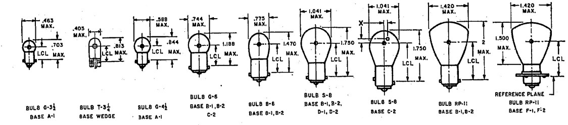
FIG. 1—BULB TYPES (THE LIGHT CENTER LENGTH (LGL) IS MEASURED FROM THE CENTER OF THE FILAMENT)
1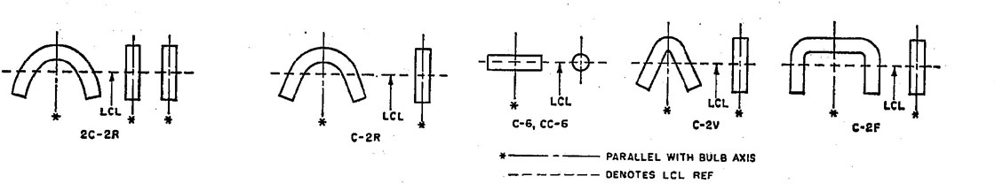
FIG. 2—FILAMENT TYPES
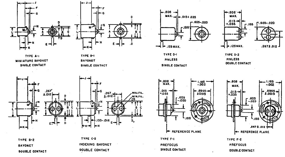
FIG. 3—BASE TYPES
| Type of Serviceb | Trade No. | Design | Rated Average Lab. Life, hr | Max Amps at Design Volts | Filament Type | Bulb Type | Dimensional Specification | Terminals | ||
|---|---|---|---|---|---|---|---|---|---|---|
| Walts | Volts | No. | Type | |||||||
| 6-V Circuits at 7.0vb | ||||||||||
| H | 6006 | 50–40 | 6.1–6.2 | 75–150 | 8.60–6.80 | C-6—C-6 | PAR 56 | Fig. 1c | 3 | Lugs |
| F | 4012 | 35 | 6.2 | 80 | 5.93 | C-6 | PAR 46 | Fig. 1d | 2 | Screws |
| F | 4015 | 35 | 6.2 | 80 | 5.93 | C-6 | PAR 36 | Fig. 2d | 2 | Screws |
| S | 4515 | 30 | 6.4 | 35 | 4.95 | C-6 | PAR 36 | Fig. 2d | 2 | Screws |
| S | 4535 | 30 | 6.4 | 35 | 4.95 | C-6 | PAR 46 | Fig. 1d | 2 | Screws |
| 12-V Circuits at 14.0Vb | ||||||||||
| H | 4001 | 37.5 | 12.8 | 200 | 3.14 | C-6 | PAR 46 | Fig. 3c | 2 | Lugs |
| H | 4002 | 37.5–50 | 12.8–12.8 | 200–320 | 3.14–4.20 | C-6—C-6 | PAR 46 | Fig. 4c | 3 | Lugs |
| H, X | 4005 | 37.5–50 | 12.8–12.8 | 240–400 | 3.14–4.20 | C-6—C-6 | PAR 46 | Fig. 4c | 3 | Lugs |
| H, X | 4006 | 37.5 | 12.8 | 240 | 3.14 | C-6 | PAR 46 | Fig. 3c | 2 | Lugs |
| S | 4404 | 30 | 12.8 | 35 | 2.58 | C-6 | PAR 36 | Fig. 2d | 2 | Screws |
| S | 4405 | 30 | 12.8 | 35 | 2.58 | CC-6 | PAR 36 | Fig. 2d | 2 | Screws |
| F | 4412 | 35 | 12.8 | 100 | 2.93 | C-6 | PAR 46 | Fig. 1d | 2 | Screws |
| F | 4415 | 35 | 12.8 | 100 | 2.93 | C-6 | PAR 36 | Fig. 2d | 2 | Screws |
| H | 6012 | 50–40 | 12.8–12.8 | 200–320 | 4.20–3.36 | C-6—C.6 | PAR 56 | Fig. 1d | 3 | Lugs |
| H, X | 6013 | 50–40 | 12.8–12.8 | 240–400 | 4.20–3.36 | C-6—C-6 | PAR 56 | Fig. 1c | 3 | Lugs |
| a Letter designations are defined as follows; F-Fog; H-Sealed Beam Headlamp; S-Spot; X-Heavy Duty Service. | ||||||||||
| b For convenience and simplification of life testing, all lamps designed for use on 6V circuits are life tested at 7V, and all lamps designed for use on 12V circuits are life tested at 14V. In general the life at average service voltages is longer. | ||||||||||
| c See SAE J571. | ||||||||||
| d See SAE J760. | ||||||||||
| Dimension | Bayonet (B-1, B-2, C-2) | Miniature (A-1) | Dimension | Bayonet (B-1, B-2, C-2) | Miniature (A-1) | Dimension | Bayonet (B-1, B-2, C-2) | Miniature (A-1) |
|---|---|---|---|---|---|---|---|---|
| Ac | 0.5925–0.6025 | 0.354–0.366 | E | 0.074–0.080 | 0.061–0.067 | K | 0.350 min | 0.180 min |
| B | 0.616–0.636 | 0.384–0.400 | F | 0.249–0.316b | 0.180–0.255 | L | 0.645 max | 0.410 max |
| C | 0.668 max | 0.432 max | H | 0.138–0.170 | 0.095–0.131 | M | 0.032 nom | 0.032 nom |
| D | 0.025 min | 0.025 min | J | 0.492–0.508 | 0.300–0.324 | N | 0.188 nom | 0.156 nom |
| a Apply to bases on complete lamp bulbs. | ||||||||
| b On bases B-2, C-2, and F-2 heights of solder contacts are to be within 0.020 in. of each other. | ||||||||
| c Both minimum and maximum to be measured with ring gage. Applies to all parts of base except within 1/8 in. from bulb end. | ||||||||
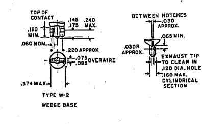
FIG. 4—BASE TYPES (BASELESS BULBS)
SAE Technical Board Rules and Regulations
3 4All technical reports. Including standards approved and practices recommended. are advisory only. Their use by any one engaged in industry or trade is entirely voluntary. There is no agreement to adhere to any SAE Standard or SAE Recommended Practice. and no commitment to conform to or be guided by any technical report.
In formulating and approving technical reports, the Technical Board, its Councils and Committees will not investigate or consider patents which may apply to the subject matter. Prospective users of the report are responsible for protecting themselves against liability for infringement of patents.
Printed in U.S.A.