In order to promote public education and public safety, equal justice for all, a better informed citizenry, the rule of law, world trade and world peace, this legal document is hereby made available on a noncommercial basis, as it is the right of all humans to know and speak the laws that govern them.
SURFACE VEHICLE RECOMMENDED PRACTICE
 J2009
J2009
Issued 1993-02-03
Submitted for recognition as an American National Standard
1. Scope—This SAE Recommended Practice applies to motor vehicle Forward Illumination Systems which use light generated by discharge sources. It provides test methods, requirements, and guidelines applicable to the special characteristics of gaseous discharge lighting devices which supplement those required for forward illumination systems using incandescent light sources. This document is intended to be a guide to standard practice and is subject to change to reflect additional experience and technical advances.
2. References
2.1 Applicable Documents—The following publications form a part of this specification to the extent specified herein. The latest issue of SAE publications shall apply.
2.1.1 SAE PUBLICATIONS—Available from SAE, 400 Commonwealth Drive, Warrendale, PA 15096-0001.
SAE J575—Tests for Motor Vehicle Lighting Devices and Components
SAE J578—Color Specification
SAE J759—Lighting Identification Code
SAE J1113—Electromagnetic Susceptibility Measurement Procedures for Vehicle Components
SAE J1211—Recommended Environmental Practices for Electronic Equipment Design
SAE J1383—Performance Requirements for Vehicle Headlamps
SAE J1816—Performance Levels and Methods of Measurement of Electromagnetic Radiation From Vehicles and Devices (Narrow Band), 10 kHz - 1000 MHz
2.1.2 ANSI PUBLICATIONS—Available from American National Standards Institute, Inc., 11 West 42nd Street, New York, NY 10036.
ANSI Z311.1—Photobiological Safety for Lamps and Lighting Systems
ANSI C78.376—Spectroradiometrically Determined Assignments
2.1.3 FMVSS PUBLICATIONS—Available from the National Highway Traffic Safety Administration, 400 Seventh Street SW, Washington, DC 20024-0002.
FMVSS 108—Lamps, Reflective Devices, and Associated Equipment (Available as 49 CFR 571.10B)
FMVSS 112—Headlamp Concealment Devices (Available as 49 CFR 571.112)
SAE Technical Standards Board Rules provide that; “This report is published by SAE to advance the state of technical and engineering sciences. The use of this report is entirely voluntary, and its applicability and suitability for any particular use, including any patent infringement arising therefrom, is the sole responsibility of the user.”
SAE reviews each technical report at least every five years at which time it may be reaffirmed, revised, or cancelled. SAE invites your written comments and suggestions.
S.A.E.
LIBRARY
Copyright 1993 Society of Automotive Engineers Inc.
All rights reserved.
Printed in U.S.A.
90-1202B EG
2.1.4 CIE PUBLICATION—Available from Commission international de L'eclairage, 52 Bd Malesherbes, F-75008 Paris, France.
CIE Pub. 13.2—Method of Measuring and Specifying Color Rendering properties of Light Sources (TC3.2) 1974
2.1.5 ACGIH PUBLICATIONS—Available from American Council of Governmental Industrial Hygienists, 6500 Glenway Avenue, Building D-7, Cincinnati, OH 45211.
Threshold Limit Values and Biological Exposure Indices for 1989-1990, American Conference of Governmental Industrial Hygienists
2.2 Definitions
2.2.1 DISCHARGE FORWARD LIGHTING (DFL) SYSTEM—An automotive lighting system, providing forward illumination, comprised of the headlamps, discharge source, ballast/starting system, and interconnecting wiring.
2.2.2 DISCHARGE SOURCE—An electric light source in which light is produced by a stabilized arc.
2.2.3 START-UP TIME—The period of time between the instant when the user operates a switch to power a lamp ON and the instant when the DFL system reaches a level within X% of “steady-state” output level.
2.2.4 RESTART—The ability of the “hot” DFL system to relight before its temperature has returned to initial ambient.
2.2.5 PHOTOMETRIC MAINTENANCE—Change in beam intensity of the test points of the beam pattern light output over time (life).
2.2.6 LIFE—Time in hours and starting cycles of a DFL system during which it meets specified operational characteristics under specified test conditions.
2.2.7 RATED LAB LIFE—Life specified by the manufacturer as the period during which the DFL system meets the performance specifications. (Rated lab life equals design life.)
2.2.8 COLOR RENDERING INDEX (LIGHT SOURCE—CRI)—Measure of the degree of color shift objects undergo when illuminated by the light source as compared with the color of those same objects when illuminated by a reference source of comparable color temperature.
2.2.9 ULTRAVIOLET RADIATION—Radiation in the spectral region between 200 and 400 nm. Definitions and terminology are adopted in accordance with proposed ANSI specification standard Z311.
2.2.10 STEADY-STATE—A condition under which the light output of the device is considered to be stable or changing at such a slow rate as to be insignificant. A “Steady-state” condition would be generally measured in terms of a “maximum percent change per time period.”
Steady-state light level (100%) is established by allowing the lamp to operate for 120s after being switched “on”.The average light level within the period from 120 to 140s will be defined as the 100% level.
2If the light output is not stable to within ± 10% during the 120 to 140s time interval, the test should be repeated on the system. If a system fails to stabilize after three attempts, a new system should be selected for a test sample.
2.2.11 AUTOMOTIVE BALLAST—A device for stabilizing the operating characteristics of a discharge lamp. The ballast contains all the necessary circuitry to ignite a lamp and cause it to operate within a specified power profile range. It controls the required light output characteristics of the automotive discharge lighting system. The ballast may consist of one or more separate components.
2.2.12 INTEGRAL BEAM—An “Integral Headlamp” produces a light pattern when normal vehicle voltage is applied. It cannot be disassembled by the user for the purpose of replacing any falled subassemblies within the lamp or housing package.
Discharge headlamps in which the ballast subunit is remote from the starter/lamp subunit, may be considered integral if the user cannot disconnect the two subunits. Such a lamp may be disassembled and serviced by the manufacturer for the purpose of recycling the assembly by replacing nonfunctioning parts. It may also be disassembled and serviced by a service factory or dealer service facility. In any case, there is the assumption that the servicing facility will certify that the performance of the serviced device will meet all standards applicable to the original equipment.
3.Lighting Identification Codes, Markings, and Notices
3.1 Headlamps shall be marked in accordance with SAE J759.
3.2 The DFL system shall contain a label indicating the presence of high voltage, e.g., the International electric shock hazard symbol (“lightning bolt”).
4. Tests—All sample DFL systems shall be seasoned for 20h prior to being subjected to the tests that follow and a new DFL system may be used for each test.
NOTE—The power supply used for all testing should have its output isolated from the input to prevent any potential danger to laboratory personnel when running test as required.
4.1 Lamp/System Starting Procedures—The headlamp shall be held in its normal operating position and mechanically aimed with a photocell or cells at the test points shown in Table 1. Tests shall be conducted at room temperature (23 °C ± 3 °C), at 12.8 VDC ± 0.1 VDC, and for a duration required to obtain a reading. The response time of the measurement instrument should be less than 100 ms.
| Lower Beam Lamp | Upper Beam Lamp |
|---|---|
| 1.5D − 2 R | H − V |
4.1.1 INITIAL START-UP—The DFL system (ballast/starter) shall be activated and the luminous intensity at the photometric test points of Table 1 sampled and recorded for each headlamp from initial actuation through the intervals specified in Figure 1 or Figure 2. The test lamp(s) is then turned off.
4.1.2 SWITCHING (COLD LAMPS)—The DFL system (ballast/starter) shall be activated and the luminous intensity at the photometric test points of Table 1 sampled and recorded for each headlamp from initial activation through the intervals specified in Figure 1 or Figure 2.
3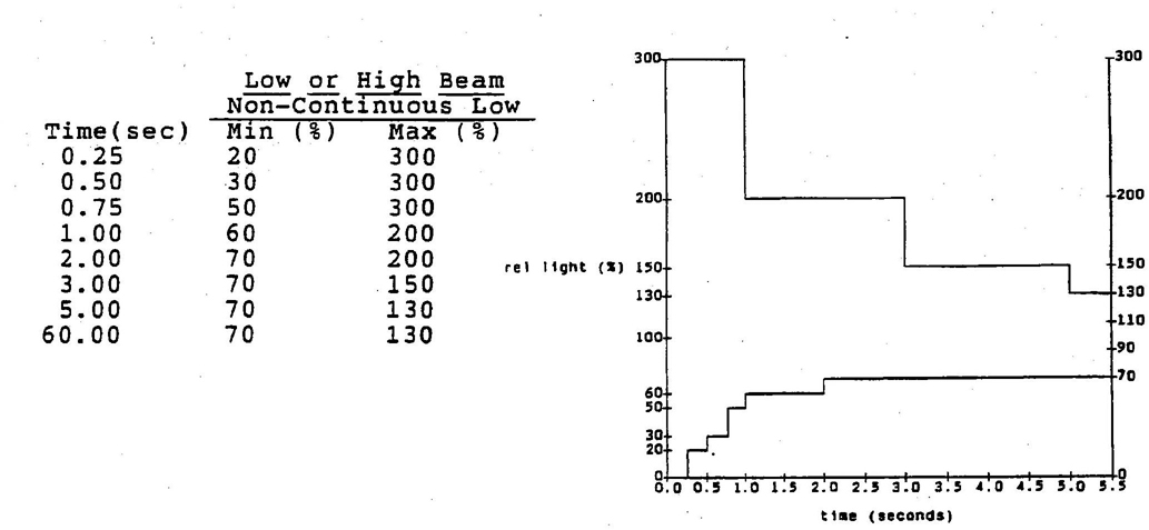
FIGURE 1—LAMP OUTPUT VS START-UP TIME LOW OR HIGH BEAM NONCONTINUOUS LOW
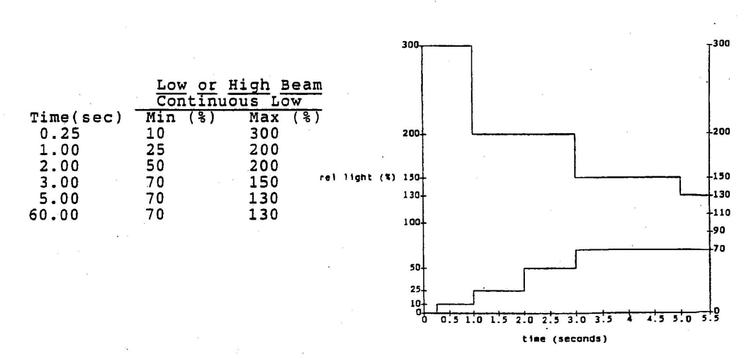
FIGURE 2—LAMP OUTPUT VS START-UP TIME LOW OR HIGH BEAM CONTINUOUS LOW
NOTE—(%) = Percent of steady-state light intensity. Each beam should be measured at the point prescribed in Table 1, with the other beam blocked or not operating.
44.1.3 SWITCHING (HOT RESTART)—The lamp shall be energized for 5 min minimum. After this time period, a restart test shall be conducted once for every time interval as follows:
a. Cool down times for DFL hot restart test—1 s, 4 s, 10 s, 20 s, 30 s, 1 min
The system shall be switched off for the period of time shown as previously stated in order to simulate momentary switching to the alternate beam. The test lamp shall be energized and the luminous intensity at the applicable photometric test point shown in Table 1 sampled.
4.1.4 SWITCHING (CONTINUOUS LOW BEAM MODE)—For DFL systems designed to have the lower beam on continuously, the lower beam lamp shall be operated during the test. However, only the photometric characteristics of the upper beam switching shall be measured. The tests for “continuous low beam mode” are identical to those described in 4.1.3 except that only the upper beam lamp is tested.
4.2 Electrical Characteristics
4.2.1 SYSTEM OPERATING WATTAGE RANGE—DFL system wattage shall be measured at 12.8 VDC ± 0.1 VDC with all components in normal operating orientation using the equipment described in 4.2.3.
4.2.2 SYSTEM OPERATING VOLTAGE RANGE—The DFL system shall operate in the regulated mode from 9.0 to 18.0 VDC with all components in normal operating orientation using the equipment described in 4.2.3. Additional considerations for voltages between 9.0 and 4.5V are presented in 6.10.
4.2.3 EQUIPMENT REQUIREMENTS—The input terminals of the DFL system shall be connected to a laboratory power supply which shall have a range of voltages from at least 4.0 to 18.5 VDC and which shall be capable of controlling voltage to ± 0.1 VDC input voltage. In addition, the power supply shall be capable of satisfying the DFL system's current drain in all operational modes.
4.3 Photometric Maintenance—The DFL system shall be operated under nominal laboratory operating test conditions (23 °C ± 3°C) at 12.8 VDC ± 0.1 VDC input voltage. The test cycle shall be the same as for the life test (6.2). The photometric maintenance test shall be performed after 70% of rated life of operation (e.g., 1400h for a 2000h design value of rated life).
4.4 Color and CRI
4.4.1 COLOR—The color coordinates shall be tested and fall within the chromaticity limits in SAE J578 for “White” light.
4.4.2 COLOR RENDERING—The color rendering properties of a DFL system shall be determined using the procedure outlined in CIE Publication Number 13.2 (TC 3.2) 1974, “Method of measuring and specifying color rendering properties of light sources.” See 6.8 for performance criteria.
4.5 Environmental Tests—Testing shall be accomplished on a complete DFL system, i.e., ballast, interconnections, and headlamp unless otherwise specified in the specific test.
54.5.1 LEAKAGE CURRENT/BREAKDOWN TEST—The test shall be made on a system positioned in its design orientation by completely covering the exterior of the DFL system to be tested with aluminum foil. The foil is to be connected to a current-sensing device which terminates at the power source common (chassis ground). The sensing device shall be a noninductive resistor of 1000ω. The leakage current occurring during starting and operating (transient and steady-state) shall be measured using an oscilloscope with a bandwidth capability five times the bandwidth being measured for the observed frequencies and rise times. Current readings shall be recorded during the first 10s of the initial start. The unit shall then continue to operate for 30 min, be turned off, and immediately restarted. The current readings shall again be recorded during the first 10s after restart. After completion of this procedure, and without submitting the unit to any other tests, the environmental test shall be carried out on the unit. Within 30 min of the completion of the environmental test, the breakdown test shall be repeated. The final readings are then compared with the respective (initial and 30 min) readings made before the environmental test.
4.5.2 THERMAL CYCLE—A DFL system shall be mounted on a test fixture in its design orientation and shall be exposed to the test described in J1383 “Thermal Cycle Test.” In addition, electronic components shall be subjected to the test in SAE J1211, Section 4.1 using conditions that are appropriate for the location of the DFL system components in the vehicle.
4.5.3 HUMIDITY—The DFL system shall be mounted on a test fixture in its design orientation and shall be subjected to the test described in SAE J1383 “Humidity Test.”. The DFL system shall be tested before and after the humidity test in accordance with the Breakdown Test in 4.5.1. Photometric testing shall begin at 10 min± 1 min following completion of the humidity test. In addition, electronic components shall be subjected to the test in SAE J1211 Section 4.2 using conditions that are appropriate for the location of the DFL system components in the vehicle.
4.5.4 INTERNAL HEAT TEST— The DFL system shall be subjected to the conditions specified in SAE J1383 “Internal Heat Test.” The DFL system shall be tested before and after the internal heat test in accordance with the Breakdown Test in 4.5.1.
4.5.5 DUST TEST—Conducted per SAE J575 Section 4.3. “DFL System” replaces “Headlamp” in the specifications. The DFL system shall be tested before and after the dust test in accordance with the Breakdown Test in 4.5.1.
4.5.6 CORROSION TEST—Test the DFL system per J575 Section 4.4. “DFL System” replaces “Headlamp” in the test. The DFL system shall be tested before and after the corrosion test in accordance with the Breakdown Test in 4.5.1.
4.5.7 CHEMICAL RESISTANCE TEST—The DFL system shall be tested per SAE J1383 “Chemical Resistance Test,” except “DFL System” replaces “Headlamp” in the test. In addition, electronic components shall be subjected to the test specified in SAE J1211 Section 4.4 using conditions that are appropriate for the location of the DFL system components in the vehicle. The DFL system shall be tested before and after the chemical test in accordance with the Breakdown Test in 4.5.1.
4.5.8 VIBRATION TEST—The DFL system shall be tested as specified in SAE J575 Section 4.1 except “DFL System” replaces “Headlamp” in the test. In addition, electronic components shall be subjected to SAE J1211 Section 4.7 and 4.8 using conditions that are appropriate for the location of the DFL system components in the vehicle. The DFL system shall be tested before and after the vibration test in accordance with the Breakdown Test in 4.5.1.
4.5.9 ALTITUDE TEST—Electronic components shall be subjected to the requirements of Section 4.6 of SAE J1211 using conditions that are appropriate for the location of the DFL system components in the vehicle. The DFL system shall also be tested before and after the altitude test in accordance with the Breakdown Test in 4.5.1.
64.6 Photometry—The DFL system shall first be seasoned (per Section 4) at the nominal ballast input voltage of 12.8V ± 0.1 V. The seasoned DFL system shall be aimed and after attaining steady-state conditions as specified in 6.5, be photometered to SAE J1383 requirements. Photometric measurements shall be made at a minimum distance of 18.3m (60 ft) from the unit.
4.7 Electromagnetic Susceptibility (EMS)—The DFL system shall be tested to SAE J1113 (guidelines and test methods Sections 2 through 9) to evaluate compatibility with potential sources of EMI.
4.8 Electromagnetic Radiation (EMR)—DFL systems shall be tested in accordance with the guidelines of SAE J1816.
4.9 Life—DFL system(s) shall be mounted in its design orientation and operated using the following cycle to determine DFL system life. The “life test cycle” is a 1h cycle, starting with five 10 min lighted cycles (50 min total). The operating cycle is 9 min 45 s“On” and 15s “Off”. Following the fifth operating cycle, the lamp is allowed to cool in the “Off” state for 10 min (81.25% hot time). When the DFL system “hot time” reaches 70% of rated lab life, the DFL system shall be subjected to the tests of 4.1 (starting procedures), 4.4 (color), and 4.5.1 (breakdown). Upon completion of the previous tests, the DFL system is returned to the life test cycle listed in Table 2 until it fails to restart (meet Figure 1 or Figure 2) following any off period. Test result guidelines are covered in 6.2.
| Cycle | Cycle Time (Minutes) | Total (Min) | |
|---|---|---|---|
| 1-Operating Cycle | (9:45 on, 0:15 off) | = | 10 |
| 1-Operating Cycle | (9:45 on, 0:15 off) | = | 10 |
| 1-Operating Cycle | (9:45 on, 0:15 off) | = | 10 |
| 1-Operating Cycle | (9:45 on, 0:15 off) | = | 10 |
| 1-Operating Cycle | (9:45 on, 0:15 off) | = | 10 |
| 1-Off Cycle | = | 10 | |
| Total Life test cycle | = | 60 min |
4.10 UV Test—UV radiation refers to the radiation in the spectral region between 200 and 400 nm.
7The measurement setup shall be as shown in Figure 1 of ANSI Z311 and the radiation sensor shall be located at a specified distance from the source (typically 50 cm). The source is defined as a lamp without any outermost lens(es). Energy levels shall be recorded at 10 nm intervals over the UV range.
UV weighting factors are defined in tables in ANSI Z311. (ANSI and NIOSH use the same tables. DIN values are also defined.)
5. Performance Requirements
5.1 Lamp/System Starting Procedures
5.1.1 INITIAL START-UP—Start-up Intensities shall conform to Figure 1 or Figure 2. The test lamp photometric values shall meet the percent of the minimum values specified in J1383 for the test points in Table 1.
5.1.2 SWITCHING (COLD LAMPS)—Figure 1 or Figure 2 indicates the acceptable percent of steady-state light intensity versus time after a cold DFL lamp has been turned on, for DFL systems with noncontinuous and continuous low beam illumination, respectively. The lamp shall produce not less than the percent of the minimum light level specified in J1383 for the test points shown in Table 1. For DFL systems which are designed for “continuous”low beam operation, see 5.1.4.
5.1.3 SWITCHING (HOT RESTART)—After a thermally stabilized DFL headlamp has been allowed to cool for varying periods of time as shown in 4.1.3a, upon restart it shall produce not less than the percentage indicated in Figure 1 or Figure 2 of the luminous intensity values given in J1383 for the test points shown in Table 1. For DFL systems which are designed for “continuous” low beam operation, see 5.1.4.
5.1.4 For DFL systems which are designed for “continuous” low beam operation, the luminous intensity of the low beam at the upper beam test point is combined with that of the upper beam to determine conformance to this specification.
5.2 Electrical Characteristics
5.2.1 SYSTEM OPERATING WATTAGE RANGE—At an input voltage of 12.8 V, the power consumption of the DFL system shall stabilize at its rated value with a maximum deviation of ±7.0%.
5.2.2 SYSTEM OPERATING VOLTAGE RANGE—Ignition and hot reignition of the lamp shall occur for all voltage settings between 9.0 and 18.0 VDC, and the arc shall be maintained to a low voltage of 4.5 VDC. (Reduced lumen output is acceptable for the 4.5 to 8.9 VDC range.)
The DFL system manufacturer shall specify the DFL minimum system voltage and current required for DFL system start-up.
5.3 Photometric Maintenance—When tested in accordance with the described test procedure, the DFL system shall meet the appropriate photometric specifications of SAE J1383, except 85% initial luminous flux value replaces 90% at 70% of life.
5.4 Color—The color of light emitted from the DFL headlamp following seasoning and attaining steady-state shall fall within the white light chromaticity boundaries as defined in SAE J578. The color of light shall be within the chromaticity limits both initially and after the photometric maintenance test of 5.3. Also see 6.1.
5.5 Environmental Requirements
5.5.1 LEAKAGE CURRENT/BREAKDOWN TEST—The acceptance criteria for this test shall be based on a comparison of the initial value of leakage current measured before the environmental test and the value measured after the test. The leakage value after the environmental test shall not exceed 200% (twice) of the initial test value.
85.5.2 THERMAL CYCLE—After the test, the DFL system shall meet SAE J1383 “Thermal Cycle Requirements” without magnification. Lens warpage shall be less than 3 mm (0.118 in) when measured normal to the lens surface at the geometric center of the lens. No breakdown shall be detected when the DFL system is tested in accordance with the Breakdown Test. In addition, electronic components shall meet the requirements of Section 5 of SAE J1211 using conditions that are appropriate for the location of the DFL system components in the vehicle.
5.5.3 HUMIDITY TEST—After the test, the DFL system shall meet SAE J1383 “Humidity Requirements”without magnification, and meet the photometric requirements of SAE J1383. There shall be no evidence of breakdown during the Breakdown Test. In addition, electronic components shall meet the requirements of Section 5 of SAE J1211 using conditions that are appropriate for the location of the DFL system components in the vehicle.
5.5.4 INTERNAL HEAT—The DFL system shall meet J1383 photometry values after the internal heat test. There shall be no evidence of breakdown during the Breakdown Test. In addition, electronic components shall meet the requirements of Section 5 of SAE J1211 using conditions that are appropriate for the location of the DFL system components in the vehicle.
5.5.5 DUST TEST—The DFL system shall meet the requirements of 4.3 of SAE J575. There shall be no evidence of breakdown during the Breakdown Test. In addition, electronic components shall meet the requirements of Section 5 of SAE J1211 using conditions that are appropriate for the location of the DFL system components in the vehicle.
5.5.6 CORROSION TEST—The DFL system shall be evaluated in accordance with 4.4 of SAE J575, except “DFL System” replaces “Headlamp” in the specifications. There shall be no evidence of breakdown during the Breakdown Test. In addition, electronic components shall meet the requirements of Section 5 of SAE J1211 using conditions that are appropriate for the location of the DFL system components in the vehicle.
5.5.7 CHEMICAL RESISTANCE TEST—The DFL system shall meet SAE J1383 “Chemical Resistance Requirement,” except that “DFL System” replaces “Headlamp” in the specifications. There shall be no evidence of breakdown during the Breakdown Test. In addition, electronic components shall meet the requirements of Section 5 of SAE J1211 using conditions that are appropriate for the location of the DFL system components in the vehicle.
5.5.8 VIBRATION TEST—The DFL system shall meet the requirements specified in 4.1 of SAE J575. “DFL System” replaces “Headlamp” in the specifications. There shall be no evidence of breakdown during the Breakdown Test. In addition, electronic components shall meet the requirements of Section 5 of SAE J1211 that are appropriate for vibration tests for the location of the DFL system components in the vehicle.
5.5.9 ALTITUDE TEST—The DFL system's electronics shall comply with the applicable requirements of J1211. There shall be no evidence of breakdown during the Breakdown Test. In addition, electronic components shall meet the requirements of Section 5 of SAE J1211 using conditions that are appropriate for the location of the DFL system components in the vehicle.
5.6 Photometry—Each High and Low Beam of the DFL system shall meet the photometry specified in SAE J1383 Table 3.
5.7 Electromagnetic Susceptibility (EMS)—The DFL system shall meet the test requirements as specifically determined for the user's application and the environment. See applicable Sections 2 through 9 of SAE J1113 for guidance. After exposure to the tests in SAE J1113, the DFL system shall meet the requirements specified in 5.1.1, 5.1.2, 5.1.3, and 5.2.1.
5.8 Electromagnetic Radiation (EMR)—The DFL system shall meet the test requirements as specifically determined for the user's application and environment. See applicable sections of SAE J1816 for guidance.
96. Guidelines
6.1 Colorimetric Characteristics—Until an ANSI Standard for colorimetric characteristics is developed for mercury, sodium, xenon, and metal halide lamps, it is required that the color of the DFL beams be perceived as essentially white light by drivers (for the accurate perception of colors in order to interpret road signs and signals). For this purpose, a color rendering index value may be established.
The “WHITE” color of a DFL headlamp device is presumed to exhibit only minor localized variations from the Integrated measurement. If significant color variations exist within the projected beam, or if color changes occur during a period of time when the device is energized, the manufacturer of the device must be assured that such color will not be confused with that of an emergency warning device.
This assurance may be realized by using a panel of observers or by comparison of colorimetric measurements to standards for signal colors.
6.2 Life—Following cycle operation per 4.9 to 70% of rated life (Example–1400h for a 2000h design life), the DFL system shall meet the requirements of 5.1 (starting procedures), 5.4 (color), and 5.5.1 (breakdown). Upon completion of the previous maintenance checks, the DFL system shall be returned to cycle operation.
6.3 Voltage Regulation—The DFL system electrical supply shall be designed such that an inoperative or removed lamp will not affect the operation and performance of the remaining lamp(s) in the DFL system.
6.4 Light and Near-Infrared Radiation Exposure Limits—Manufacturers and users of DFL systems should ensure that the DFL system does not exceed the maximum allowable limit value for three retinal hazards as specified in 4.3 of the ANSI Standard Z311.1 (titled Photobiological Safety). Those three hazards are retinal thermal injury from short-term viewing (Z311.1 paragraph 4.3.1), retinal photochemical injury from chronic exposure (Z311.1 paragraph 4.3.2), and long-term ocular exposure to infrared radiation (Z311.1 paragraph 4.3.3). The three hazards cover wavelengths between 400 to 1400 nm. The measurement of the exposure levels is strongly dependent on the value used for the angular subtense of the light source (the parameter, alpha, in Z311.1). The handbook “Safety With Lasers and Other Optical Sources” by Sllney and Wolbarsht (1980, Plenum Press) is recommended as a reference.
6.5 Steady-State—Steady-state light level (100%) shall be established by allowing the DFL system to operate for 120s after being switched“on.” The average light level within the period from 120 to 140s will be defined as the 100% level. If the light output is not stable to within±10% during the 120 to 140s time interval, the process should be repeated. If the system selected does not stabilize within three attempts, another unit should be selected and subjected to the previous procedure. Steady-state is only used to define a system's baseline in order to evaluate test effects on the system.
6.6 High-Voltage Shock Safety—High-voltage shock from DFL systems is an important concern just as it is with other automotive components. Appropriate levels of safety must be designed in and other precautionary measures, such as use of caution labels, should be implemented to assure a sufficiently low level of risk. Since individual DFL products and vehicle applications will differ in regard to high voltage levels, power, and integrity of construction, each DFL system will require a specific evaluation with the system installed in the vehicle to assure a low problem potential. This is a vehicle design and testing issue and is beyond the scope of this document. Designs of replacement equipment will also need to be evaluated on specific vehicle models for which they are intended.
1Current fluorescent lamp chromaticity standards in the United States are now based on spectroradiometrically determined assignments by the National Institute of Standards and Technology. Refer to ANSI C78.376-1969.
106.7 High-Voltage Vapor Ignition Safety—Protection from the possibility of vapor ignition from DFL high voltages is a concern. However, the concerns of vapor ignition are not too much different from those experienced from damaged high-voltage ignition systems, shorted and burning wiring, and exposed hot bulbs and filaments. Furthermore, the safety of a DFL system depends not only on its basic design, but also upon the design of the vehicle in which it is installed. Each vehicle application, therefore, needs to be individually evaluated as a complete DFL system in the vehicle to assure a low level of risk. This is a vehicle design and testing issue and is beyond the scope of this document.
6.8 CRI—The color rendering index shall meet the general criteria of Ra = 60. Each source manufacturer and user shall determine that the light produced shall readily allow the customer to distinguish between typical road sign colors.
6.9 UV Test—UV weighting factors defined in ANSI Z311 (ANSI and NIOSH use the same tables, DIN tables are also defined) shall be used to determine time for minimum effect. Measurements shall be made in accordance with 4.10. (See Table 3 for examples.)
| Standard | Type | Time for Min. Effect |
|---|---|---|
| NIOSH (200-320) | ERYTH | 124.4 h |
| DIN (240-325) | ERYTH | 677.6 |
| DIN (300-440) | PIGMT | 26.0 |
| DIN (220-305) | CONJT | 29435. |
The ANSI Z311 Standard shall be used (voluntary draft at present). Energy level to be determined by application.
It is recognized that ultraviolet radiation (UV) normally emitted by arc discharge sources may pose health hazards at certain levels and durations of exposure. The magnitudes of acceptable levels of exposure are outlined in documents such as those published by NIOSH or ACGIH (American Conference of Governmental Industrial Hygienists). These tables may be used as references when determining the exposure potential of DFL headlamps.
The concern with UV light may be addressed by the device manufacturer by using shields, coatings, and/or absorbing materials. It is anticipated that most lens materials will normally provide safe UV levels by absorption/reflection. However, where the possibility exists that lens protection may be lost while the arc source remains functional (stone damage or low-energy impact), it is the device manufacturer's responsibility to assure that protection from UV is provided to all who may be exposed to the light.
6.10 System Operating Voltage Range—Vehicles are designed to continue operating at voltage levels below 9.0 V. The vehicle manufacturers must define acceptable reductions in light output for voltages below 9.0V and determine system dropout voltage.
PREPARED BY THE SAE ROAD ILLUMINATION DEVICES STANDARDS COMMITTEE
11Rationale
1. Scope—Light for the DFL system is generated by a gaseous electrical discharge source. The light source is composed of a confining vessel, referred to as an envelope or tube, and contains a variety of elements typically including mercury, metal halide salts, and a rare gas. The discharge is maintained between electrodes composed of tungsten or related material. The discharge and surrounding envelope taken as a unit is called a discharge source.
The discharge source must be operated with an auxiliary power regulator called a ballast. The ballast performs the functions of initiating the discharge and regulating the electrical properties of the source.
The discharge source and ballast, when combined with a suitable reflector/lens assembly, forms the DISCHARGE FORWARD LIGHTING (DFL) system.
1.1 Replacement Compatibility—This document has been formulated so as to avoid requirements or guidelines which could restrict technical progress. Changes are expected in distribution voltage, different arc-tube technologies for performance gains, lower starting voltages, faster warm-up, shorter arc gaps, improved color, etc. This recommended practice is directed toward functional requirements associated with discharge sources. Much of the rationale is based on the assumption that the DFL system will have a significantly longer life than current headlamp systems.
2.13 Steady-State—DFL systems typically have a continuous low level of variation/oscillation in light output. Steady-state light level (100%) must be defined in order to establish a baseline for photometric testing. The definition was established to allow the selection of a system as a test sample. If a system fails to stabilize to within ± 10% during the 120 to 140s time interval within three attempts, a different system should be selected for testing.
4. Seasoning—DFL system operating characteristics differ from filament lamps. Unlike filament lamps where lumen drop off occurs at a relatively steady rate over life, DFL system lumens drop rapidly during the initial burning hours and then tend toward a more level rate of drop around 100 h. Depending on the DFL system design, this initial lumen drop could be 5 to 10%. With the long lives anticipated for DFL systems (2000 or more hours), test procedures need to address performance over the longer time interval. DFL systems will, therefore, require longer seasoning times to stablize photometry. However, seasoning for 100h is not practical. 20h seasoning was agreed upon as a reasonable compromise.
12If a higher degree of maintenance accuracy is required, an alternate seasoning method could be used to monitor the light intensity at one test point. Start the photometric test after the rate of change has stabilized at (X), where X is defined as:
X = 100 (lt−1 − lt)/lt−1 (Eq.1)
where:
l = light intensity
t = now
t−1 = 1h ago
“Stability” would be considered as three consecutive hours (or some other agreed period) at or below X. Assuming 90% initial intensity at 100h and 80% at a projected life of 2100h gives a value for:
X = 100 (90 − 80)/(2100 − 100) = 100 (0.005) %/h
So X should be ≤0.005 (suggested value) for three consecutive hours before starting the photometric test.
4.1 DFL Starting—DFL starting tests are divided into two areas. The first is concerned with the initial application of power to the DFL system (start-up). The second (restart) test involves switching between upper and lower beam modes both for hot and cold lamps.
Some DFL system designs are envisaged in which the arc source lamp is maintained in a “warm” state by a heating element. In this case it is necessary to accommodate the initial time interval which is needed to overcome the thermal mass of the heater and arc tube when the DFL system is first energized (presumably when the vehicle is started). It is anticipated that once this DFL system has achieved its proper thermal state, it will be ready to be activated, more or less instantaneously, in the switching (or restart) mode.
In order to recognize the different methods which may be used to satisfy the driver's lighting needs, it was necessary to create two separate specifications for the two distinct “starting” situations.
4.1.1 INITIALSTART-UP—When a DFL system is first energized, it is necessary that the lamps reach full output in a reasonable period of time. As a guideline, FMVSS 112 allows a time period of 3s for lamp systems commonly referred to as “pop-up” or“retractable” headlamps. DFL lamps are expected to reach approximate full output level within a comparable time period.
4.1.2 SWITCHING—When DFL lamps are switched between upper and lower beam modes, the driver's expectations and needs are such that the lamps should provide an acceptable level of light in a much shorter period of time. The light levels must be sufficient to delineate potential obstacles; and, in the high beam mode the driver must have visual verification that the selected DFL system is activated.
The proposed tables for both continuous and noncontinuous low-beam operating DFL systems were based on test data and test car experience.
4.2 Electrical Characteristics—The (electronic) ballast must have the capability to ignite the discharge source and stabilize it at its rated power consumption (after a short run-up period) under all electrical conditions which may be present during normal motor vehicle operation. All possible conditions of the vehicle power supply must be known and simulated, i.e., essentially voltage range and operation mode transients. The maximum loading of the power supply by the DFL system must also be considered.
4.2.1 SYSTEMOPERATINGWATTAGE RANGE—Typically, incandescent (and halogen) lamp wattage varies between 77% and 144% for operating voltage variations between 11.0 and 16.0 V, respectively. The DFL system should be capable of stabilizing wattage within this range. In fact, wattage regulation between 9.0 to 18.0 VDC will be required.
4.2.2 SYSTEMOPERATINGVOLTAGE RANGE—Vehicle operating voltage range has been demonstrated to vary between 9.0 and 18.0 VDC. The DFL system must regulate light output and meet J1383 over this voltage range.
4.3 Photometric Maintenance—This test determines light output loss over time for the DFL system. Factors such as quartz devitrification, color of light generated, change in arc characteristics of the discharge source, and headlamp deterioration can result in a reduction of the photometric output of the DFL system. In addition, DFL lamps' operating characteristics differ from filament lamps. Lumens drop rapidly during the initial burning hours and then tend toward a more level rate of drop around 100 h. Each DFL system shall meet respective SAE specifications for the life of the DFL system. Measurement of lumen output or beam intensity shall be made after operating the headlamp for the specified hours and cycles.
4.4 Color and Color Rendering—Light generated by a discharge source composed of gases that radiate in selective color bands (line spectrum) will appear white when properly formulated. The spectral distribution is different than that of a typical tungsten incandescent source. Thus, discharge sources require additional specifications to guarantee sufficient color discrimination and to avoid misidentifying colors, e.g., a red sign appearing yellow-orange. The CRI system was based on deviations from a smooth Planckian distribution for pastel colors. With the noncontinuous distribution of the discharge source, it becomes possible for two lamps with the same CRI value to be very different in their ability to perform the task of traffic sign recognition.
13Alternatives for controlling color rendering were discussed:- i.e., minimum energies for red, yellow, and blue wavelength bands; using the present Ra color rendering method; and/or specifying minimum values for R9, R10, and R12. All had obvious shortcomings.
A method needs to be developed that is more specific to the task of color recognition/differentiation of traffic signs, and incorporates work on visual clarity, etc. Waiting for that development could leave the standard without any defined specification for several years. Therefore, as an interim measure a minimum value of Ra = 60 (per the standard CRI system) was selected as a guideline.
This value was based on measurements of various actual sources, values obtained for a “Thornton” source, visual appraisal of pure mercury sources as being less than satisfactory, and the fact that all existing discharge systems in use today fall within this specification and appear to perform satisfactorily.
Color is to be measured in an integrating sphere with the lamp operating in its steady-state condition. There is no attempt to address the color at specific point locations nor to address color variations prior to steady-state operation. It is incumbent on the manufacturer of the DFL system to make certain that any light projected by the DFL system will not: a) be perceived as a warning device by an observer looking at the lamp, b) project color variations to cause misinterpretation of signs. It is suggested that the design of the beam pattern be such that excessive [>600 K] color changes are minimized within the primary portion of the beam pattern; ± 4 degrees up-down and ± 15 degrees left-right. This should not be interpreted that there will be no visible color fringes within this area.
4.4.1 COLOR ANDCOLOR VARIATIONS—In reference to Appendix A.1 of SAE J578, Section 2; this section was written to apply in particular to signal lamps in order to control the amount of light leakage from adjacent colored lenses. Discharge light source color fringes are not appreciable in the total beam pattern. They may be dynamic during arc initiation and may exist in small areas of the total beam pattern during steady-state operation.
4.5 Environmental Tests—The standard headlamp tests of SAE J575, J1383, and FMVSS 108 have been incorporated (and modified as noted) for the DFL system. In addition, SAE J1211 was incorporated for the electrical components as applicable.
4.5.1 LEAKAGECURRENT/BREAKDOWNTEST—The intent of this test is to evaluate if there is damage to the structure of the DFL system by the environmental tests. There is an underlying assumption that manufacturers and users will exhibit caution to minimize any current leakage with their designs. Because construction, materials, and physical configuration can be considerably different from one DFL system to another, a standard value for leakage current limits cannot be set. Rather, the criteria for this test is based on the need to detect a change in the structural integrity of the DFL enclosure which could cause electrical leakage paths from passing from the lamp interior to the exterior. Since the initial values will be very low, the criteria of no more than 200% change in leakage was selected as an indication of structure affect during testing.
4.6 Photometry—The DFL system should meet the photometric requirements for the latest approved headlamp systems (Type F) as specified in SAE J1383. This will allow manufacturers the option of choosing between package size and improved performance without a reduction in safe driving conditions.
4.7 Electromagnetic Susceptibility (EMS)—DFL systems may be susceptible to conducted or radiated electromagnetic, transient, or steady-state energy from onboard or external sources. SAE J1113 provides guidelines and test methods for evaluating compatibility with potential sources of EMI. Users of DFL systems should test to the extent necessary to assure compatibility with the user's application and environment.
4.8 Electromagnetic Radiation (EMR)—It is possible that DFL systems may emit electromagnetic energy which could affect the operation of electronic devices onboard or external devices. Since standards for EMR levels do not presently exist to completely cover both narrow and broadband emissions, users of DFL systems should test to the extent necessary to assure compatibility with the application and environment. Standards are presently being developed by the SAE EMR committee. However, SAE J1816 provides guidance in this [Illegible Text Omitted on Page 14]
144.9 Life—Life of the total DFL system is measured in both hot hours and starting cycles. The test addresses hot and cold restarts, hours of operation, and DFL system light output levels at 70% of design service life under environmental conditions.
4.10 UV (Ultraviolet)—The intent here is to define the worst case UV exposure risk from damaged lamps. Therefore, testing should be conducted on a reflector assembly with the arc tube at its design position without a lens attached. This assembly configuration will produce the maximum UV energy that can be directed to a person in the event lens separation occurs in service.
6.2 Life—DFL systems are expected to have significantly longer life than current headlights. As DFL systems develop, the average life could very well extend to many times the life of the car. Consequently, a definition of “average rated lab life” would not be practical as a measure of life. Lab testing to determine the average life would be impractical, costly, and unnecessary. An alternate method of specifying DFL system life could be based on the relative number of systems surviving a specified time period, such as 75% survival at 2000 h. There may be many other ways to rate life which may be as appropriate for DFL systems.
The life of a DFL system can be affected by the number of starts, temperature, total operating time, etc. The lab life test defined addresses these issues and requires a reasonable test time to allow monitoring of the DFL system design/production. 10 000 cycles and 2000h of operating were determined to be practical figures for lamp operation based on automotive manufacturers' usage data. Typically, headlamps are measured for maintenance at 70% of rated life. For example, this would translate to a 1400h (7000 cycle) interval for maintenance measurements. Acceptable maintenance was defined as the ability to meet the standards for photometry, environment, temperature cycle, color, and humidity following 70% of the “life tests.” Lab life tests should—over time—equal “average rated lab life.” It is known that some DFL system/components will operate longer, some shorter. Average lab life is that obtained in closely controlled laboratory testing of DFL system/components at specified test conditions.
6.3 Voltage Regulation—Loss of a lamp in a DFL system shall not prevent another lamp(s) in the system from operating and meeting its minimum requirements.
6.4 Light and Near-Infrared Radiation Exposure Limits—Depending on discharge chemistry and lamp optics, some DFL systems could emit sufficient visible light, or near-infrared radiation, to be hazardous to the retina. Preliminary investigations suggest that some DFL systems could approach the maximum allowable exposure limits if the brightest part of the beam is viewed from close proximity (1m distance).
6.6 High-Voltage Shock Safety—Protection from high-voltage shock from DFL systems is an important safety concern just as is the safety of other automotive products such as ball joints, gas tanks, and H.V. ignitions. In general, the safety of such products can never reach 100%; however, appropriate levels of safety are designed in and other precautionary measures are implemented to assure a sufficiently low level of risk. Since individual DFL products and vehicle applications will differ in regard to high voltage levels, power, and integrity of construction, each DFL system and particular vehicle application requires an individual evaluation at the vehicle level to assure a low problem potential. Because this is a vehicle level issue it is beyond the scope of this document and should not be addressed by a specific test.
6.7 High-Voltage Vapor Ignition Safety—The possibility of vapor ignition by DFL high voltage is a concern just as is the concern for protection from high voltage shock. However, the concerns and the probability of vapor ignition are similar to that which has been experienced from damaged high voltage ignition systems, shorted and burning wiring, and exposed hot bulbs and filaments. Furthermore, the safety of a DFL system is not solely dependent on its basic design, but also upon the design of the vehicle in which it is installed. Each vehicle application, therefore, needs to be individually evaluated as a composite DFL system in the vehicle to assure a low level of risk. Because this is a vehicle level concern, it is beyond the scope of this document and shall not be addressed by a specific test.
156.10 Vehicles are designed to continue to operate to a low voltage level of about 4.5 VDC under certain conditions. At 4.5 V, a typical headlamp produces approximately 2% of its 12.8V intensity. Light output requirements become a safety and philosophical issue—Which is safer? Should lights be allowed to dim to allow the vehicle to maneuver out of traffic, or should a minimum light level be specified until the vehicle stops? This question must be answered by each vehicle manufacturer. Therefore, this document cannot address this issue for voltages under 9.0 V.
Relationship of SAE Standard to ISO Standard—Not applicable.
Application—This SAE Recommended Practice applies to motor vehicle Forward Illumination Systems which use light generated by discharge sources. It provides test methods, requirements, and guidelines applicable to the special characteristics of gaseous discharge lighting devices which supplement those required for forward illumination systems using incandescent light sources. This document is intended to be a guide to standard practice and is subject to change to reflect additional experience and technical advances.
Reference Section
SAE J575—Tests for Motor Vehicle Lighting Devices and Components
SAE J578—Color Specification
SAE J759—Lighting Identification Code
SAE J1113—Electromagnetic Susceptibility Measurement Procedures for Vehicle Components
SAE J1211—Recommended Environmental Practices for Electronic Equipment Design
SAE J1383—Performance Requirements for Vehicle Headlamps
SAE J1816—Performance Levels and Methods of Measurement of Electromagnetic Radiation From Vehicles and Devices (Narrow Band), 10 kHz - 1000 MHz
ANSI Z311.1—Photobiological Safety for Lamps and Lighting Systems
ANSI C78.376—Spectroradiometrically Determined Assignments
FMVSS 108—Lamps, Reflective Devices, and Associated Equipment
FMVSS 112—Headlamp Concealment Devices
CIE Pub. 13.2—Method of Measuring and Specifying Color Rendering Properties of Light Sources (TC3.2) 1974
Threshold Limit Values and Biological Exposure Indices for 1989-1990, American Conference of Governmental Industrial Hygienists
Developed by the SAE Road Illumination Devices Standards Committee
16