
In order to promote public education and public safety, equal justice for all, a better informed citizenry, the rule of law, world trade and world peace, this legal document is hereby made available on a noncommercial basis, as it is the right of all humans to know and speak the laws that govern them.
SURFACE VEHICLE INFORMATION REPORT
 , J1733 ISSUED DEC 94
Issued 1994-12
Submitted for recognition as an American National Standard
Foreword—This Document has not changed other than to put it into the new SAE Technical Standards Board Format.
1. Scope—In order to compare test results obtained from different crash test facilities, standardized coordinate systems need to be defined for crash test dummies, vehicle structures, and laboratory fixtures. In addition, recorded polarities for various transducer outputs need to be defined relative to positive directions of the appropriate coordinate systems. This SAE Information Report describes the standardized sign convention and recorded output polarities for various transducers used in crash testing.
2. References
2.1 Applicable Publications—The following publications form a part of the specification to the extent specified herein. Unless otherwise indicated the latest revision of SAE publications shall apply.
2.1.1 SAE PUBLICATIONS—Available from SAE, 400 Commonwealth Drive, Warrendale, PA 15096-0001.
SAE 211—Instrumentation for Impact Test
SAE J670—Vehicle Dynamics Terminology
SAE J1594—Vehicle Aerodynamics Terminology
SAE J2052—Test Device Head Contact Duration Analysis
3. Right-Handed Coordinate System—A right-handed coordinate system consists of an ordered set of three mutually perpendicular axes (x, y, z) which have a common origin and whose positive directions point in the same directions as the ordered set of the thumb, forefinger, and middle finger of the right hand when positioned as shown in Figure 1. One can choose the positive x-axis to point in the direction of either the thumb, forefinger, or middle finger as shown in the configurations 1, 2, and 3 of Figure 1. However, once this decision is made then the positive directions of the y and z axes must be as indicated by the corresponding configuration shown in Figure 1. Note that these three configurations of x, y, z axes always define a right-handed coordinate system independent of the orientation of the Sections 4 and 5 will define standardized orientations of coordinate systems for the vehicle and dummy, respectively.
SAE Technical Standards Board Rules Provide that: “This report is published by SAT to advance the state of technical and engineering. The use of this report is entirely voluntary, and its application and suitability for any particular use, including any patent infringement therefrom, is the sole responsibility of the user.”
SAT reviews each technical report at least every five years at which time it may be reaffirmed, revised, or cancelled. SAE invites your written comments and suggestions.
QUESTION REGARDING THIS DOCUMENT: (724) 772-8512 FAX: (724) 776-0243
TO PLACE A DOCUMENT ORDER; (724) 776-4970 FAX: (724) 776-0790
SAE WEB ADDRESS http://www.sae.org
Copyright 1994 Society of Automotive Engineers, Inc,
All rights reserved.
Printed In U.S.A
1Positive angular motion and moment directions are determined by the right-handed screw rule. If any of the three positive axes is grasped with the right hand with the thumb extended in the positive direction, as shown in Figure 2 for the x-axis, then the curl of the fingers indicate the positive direction for angular motions and moments with respect to that axis.
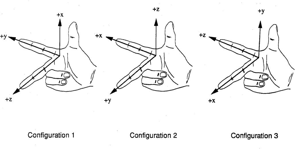
FIGURE 1—THE THREE POSSIBLE CONFIGURATIONS OF A RIGHT-HANDED COORDINATE SYSTEM RELATIVE TO THE THUMB, FOREFINGER, AND MIDDLE FINGER OF THE RIGHT HAND
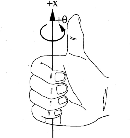
FIGURE 2—RIGHT-HANDED SCREW RULE
2A simple method to determine if a coordinate system is right-handed is to rotate the system 90 degrees about any of one of its positive axes using the right-handed screw rule. For a positive 90 degrees rotation about the +x-axis, the coordinate system is right-handed if the +y-axis rotates to the position previously occupied by the +z-axis. For a positive 90 degrees rotation about the +y-axis, the coordinate system is right-handed if the +z-axis, rotates to the position previously occupied by the +x-axis. For a positive 90 degrees rotation about the +z-axis, the coordinate system is right-handed if the +x-axis rotates to the position previously occupied by the +y-axis.
4. Vechicle Coordinate Systems—Vehicle coordinate systems will be consistent with the orientations specified in SAE J670 and SAE J1594. These orientations are shown in Figures 3 and 4, respectively. For structures within the vehicle that have a principle axis of motion such as the steering wheel column, the vehicle coordinate system may be rotated about the y-axis such that the +x-axis or +z-axis is directed along the column axis.
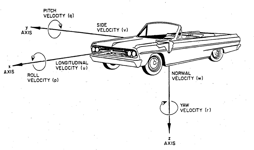
FIGURE 3—VEHICLE DYNAMICS COORDINATE SYSTEM—SAE J760
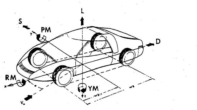
FIGURE 4—VEHICLE AERODYNAMICS COORDINATE SYSTEM—SAE J1594
35. Dummy Coordinate Systems—The definition of the dummy coordinate system given in SAE J211 will be used. A coordinate system can be affixed to any point on the dummy. The coordinate system will translate and/or rotate with the dummy part to which it is attached during the test. To define standard orientations of the directed forward, the +y-axis will be directed from the dummy's left to its right side and the +z-axis will be anterior (P-A), the +y-axis is directed from left to right (L-R), and the +z-axis is directed from superior to inferior (S-1). Figure 5 shows examples of this standardized orientation for coordinate systems attached to a few body points. Note that as the dummy is articulated to sit in a vehicle or during a test the coordinate systems rotate with their respective dummy parts.
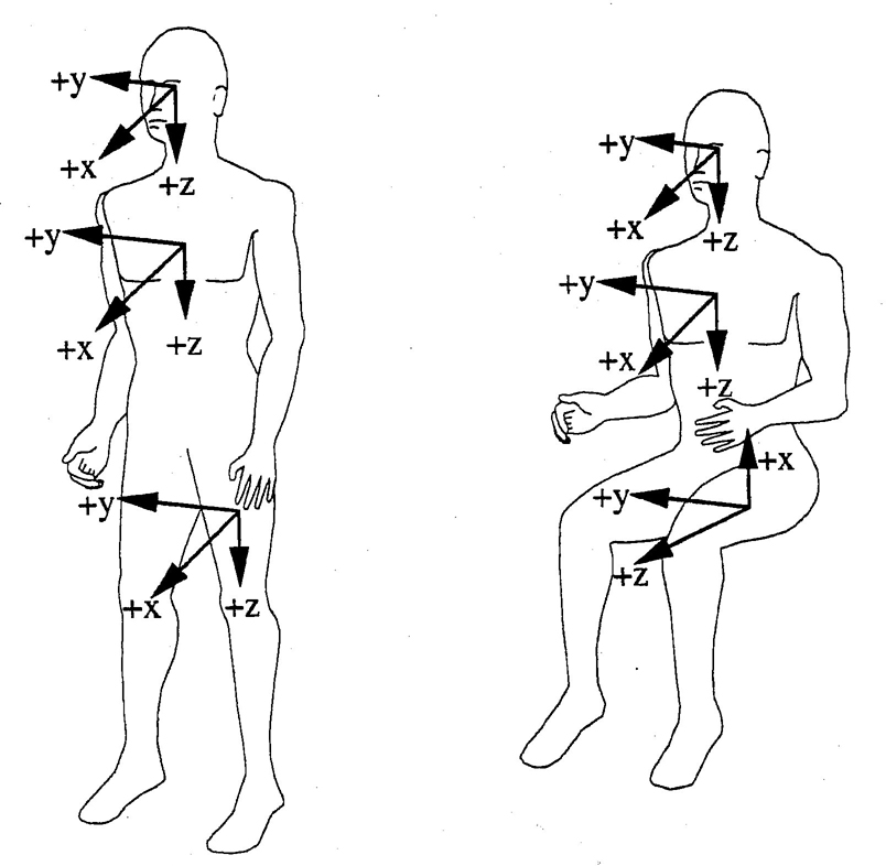
FIGURE 5—ORIENTATIONS OF STANDARDIZED DUMMY COORDINATE SYSTEMS FOR STANDING AND SEATED POSTURES
46. Standard Polarities for Recorded Dummy Measurements
6.1 Polarities of Acceleration, Velocity, and Displacement—Positive recorded outputs for these transducers are to be consistent with the positive axes of the coordinate system defined for the specific dummy or vehicle point being measured. In general, for any dummy component oriented in its standard standing position, blows to its back side, left side, and top will produce positive accelerations relative to its +x, +y, and +z directions, respectively. As illustrated in Figure 6, a blow to the back of the dummy's head produces an acceleration in the forward direction (+x) which should be recorded as a positive acceleration. A blow to the top of the head produces a +z acceleration. A blow to the left side of the head produces a +y acceleration. Note that since the SID dummy is only instrumented to measure accelerations, the polarities of its transducers are determined by the methods described in this section.
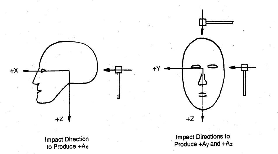
FIGURE 6—HEAD IMPACT DIRECTIONS THAT PRODUCE POSITIVE HEAD ACCELERATIONS RELATIVE TO THE HEAD COORDINATE SYSTEM
5For relative displacement of body parts, the coordinate system of interest must be defined. For example, frontal chest compression is the distance that the sternum moves relative to the thoracic spine. In this case, the coordinate system is fixed to the thoracic spine. When the sternum moves closer to the spine, its displacement is rearward relative to the spine which is in the negative x-direction. Hence, the polarity for chest displacement of the impacted ribs relative to the thoracic spine. However, a blow to the right side of the chest produces a negative rib displacement. The directions of these chest compressions are illustrated in Figure 7. The rearward displacement of the tibia relative to the femur that is measured by the knee shear transducer is in the negative x-direction. The polarity for this motion is negative.
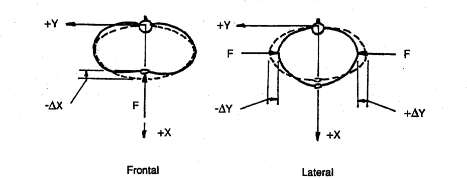
FIGURE 7—DIRECTIONS OF FRONTAL AND LATERAL CHEST COMPRESSIONS
6.2 Polarities of Measured External Loads— For load cells that measure loads applied directly to the dummy or vehicle structure, their recorded output polarities should be consistent with the direction of the applied external load referenced to the standardized coordinate system at the point of the load application. For example, load cells that measure shoulder belt loading of the clavicle are designed to measure Fx and Fz applied to the clavicle. The rearward (−x) component of the shoulder belt force applied to the clavicle should be recorded with a negative polarity. The downward (−z) component should have a positive polarity. For the BIOSID, a lateral inward load applied to the crest of the left illium (+y) would be positive, while a lateral inward load applied to the crest of the right ilium (−y) would be negative.
6.3 Polarities of Measured internal Loads—Defining recorded output polarities for load cells that measure loads internal to the dummy requires a standardized dummy sectioning scheme and a definition of what sectioned dummy part is to be loaded in the positive direction since internal loads occur in pairs of equal magnitudes but opposite directions. The standardized sectioning scheme is illustrated by the free-body diagram of a cube shown in Figure 8. It is assumed that the load cell of interest is contained within the cube and responds to loads applied to the surfaces of the cube. Load cell outputs should be recorded with positive polarities when normal loads, shear loads, torques, or moments are applied in the positive direction, as defined by the standardized coordinate system, to the right, front, and/or bottom surfaces of the cube. These loads are represented by solid arrows. For static equilibrium, equal magnitude but opposite direction loads (negative) must be applied to the left, back, and/or top surfaces of the cube as indicated by the dashed arrows.
6For example, upper and lower neck, lumbar spine, and upper and lower tibia load cells should have positive recorded outputs when the dummy is sectioned below the load cell in question and positive loads are applied to the bottom surface of the sectioned body part that contains the load cell in question. Dummy manipulations for checking the recorded polarities of the outputs of various transducers are given in Section 7. Free-body diagrams for specific dummy load cells showing the load systems that produce the required outputs that should be recorded with the specified polarities are given in Section 8.
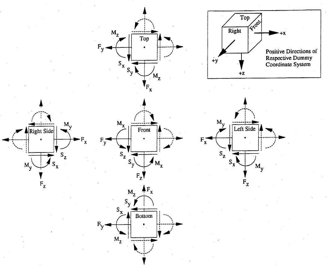
FIGURE 8—FREE-BODY DIAGRAM OF A SECTIONED DUMMY PART CONTAINING THE LOAD CELL OF INTEREST (ILLUSTRATED AS A CUBE). PRINCIPLE AXES OF LOAD CELL ALIGNED PARALLEL TO RESPECTIVE AXES OF LOCAL DUMMY COORDINATE SYSTEM. BOLD ARROWS OF NORMAL FORCES (F), SHEAR FORCES (S), AND MOMENTS (M) SHOWN IN POSITIVE DIRECTIONS AND APPLIED TO THE FRONT, RIGHT, AND BOTTOM SURFACES OF THE CUBE. DOTTED ARROWS INDICATE DIRECTION OF LOADS APPLIED TO THE BACK, LEFT, AND TOP SURFACES FOR STATIC EQUILIBRIUM. ALL LOAD CELL OUTPUTS FOR THIS LOAD SYSTEM TO BE RECORDED WITH POSITIVE POLARITIES.
77. Dummy Manipulations for Checking Polarities of Measured Loads—Table 1 contains descriptions of dummy manipulations that can be used to verify the correctness of the polarities of recorded outputs for some of the more common load cells used in dummies.
| Load Cell | Measure | Dummy Manipulations | Polarity |
|---|---|---|---|
| Upper | Fx | Head Rearward, Chest Forward | + |
| and | Fy | Head Leftward, Chest Rightward | + |
| Lower | Fz | Head Upward, Chest Downward | + |
| Neck | Mx | Left Ear Toward Left Shoulder | + |
| Loads | My | Chin Toward Sternum | + |
| Mz | Chin Toward Left Shoulder | + | |
| Left Shoulder | Fx | Left Shoulder Forward, Chest Rearward | + |
| Loads (BIOSID) | Fy | Left Shoulder Rightward, Chest Leftward | + |
| Fz | Left Shoulder Downward, Chest Upward | + | |
| Right Shoulder | Fx | Right Shoulder Forward, Chest Rearward | + |
| Loads (BIOSID) | Fy | Right Shoulder Rightward, Chest Leftward | + |
| Fz | Right Shoulder Downward, Chest Upward | + | |
| Right Shoulder | Fx | Right Shoulder Forward, Chest Rearward | + |
| Loads (BIOSID) | Fy | Right Shoulder Rightward, Chest Leftward | + |
| Fz | Right Shoulder Downward, Chest Upward | + | |
| Clavicle | Fx | Shoulder Forward, Chest Rearward | + |
| Loads | Fz | Shoulder Downward, Chest Upward | + |
| Upper | Fx | Chest Rearward, Pelvis Forward | + |
| and | Fy | Chest Leftward, Pelvis Rightward | + |
| Lower | Fz | Chest Upward, Pelvis Downward | + |
| Lumbar | Mx | Left Shoulder Toward Left Hip | + |
| Spine | My | Sternum Toward Front of Legs | + |
| Mz | Right Shoulder Forward, Left Shoulder Rearward | + | |
| Sacrum Load (BIOSID) |
Fy | Left H-Point Pad Leftward, Chest Rightward | + |
| Left lliac Load (BIOSID) |
Fy | Left Iliac Rightward, Chest Leftward | + |
| Right lliac Load (BIOSID) |
Fy | Right lliac Rightward, Chest Leftward | + |
| Public Load (Side Impact) |
Fy | Right H-Point Pad Leftward, Left Pad Rightward | (−) |
| Crotch Belt | Fx | Public Rearward, Pelvis Forward | (−) |
| Loads | Fz | Public Upward, Chest Downward | (−) |
| lliac Lap | Fx | Upper lliac Spine Rearward, Chest Forward | (−) 8 |
| Belt Loads | My | Upper lliac Spine Rearward, Chest Forward | + |
| Left Side Abdominal Load (EUROSID-1) |
Fy | Left Side of Abdomen Rightward, Chest Leftward | + |
| Right Side Abdominal Load (EUROSID-1) |
Fy | Right Side of Abdomen Leftward, Chest Rightward | (−) |
| Femur | Fx | Knee Upward, Upper Femur Downward | + |
| Loads | Fy | Knee Rightward, Upper Femur Leftward | + |
| (Dummy in | Fz | Knee Forward, Pelvis Rearward | + |
| Seated Position, | Mx | Knee Leftward, Hold Upper Femur in Place | + |
| Femurs | My | Knee Upward, Hold Upper Femur in Place | + |
| Horizontal) | Mz | Tibia Leftward, Hold Pelvis in Place | + |
| Knee Clevis | Fz | Tibia Downward, Femur Upward | + |
| Upper Tibia | Fz | Tibia Downward, Femur Upward | + |
| Loads | Mx | Ankle Leftward, Hold Knee in Place | + |
| My | Ankle Forward, Bottom of Knee Clevis Rearward | + | |
| Lower Tibia | Fx | Ankle Forward, Knee Rearward | + |
| Loads | Fy | Ankle Rightward, Knee Leftward | + |
| Fz | Ankle Downward, Knee Upward | + | |
| Mx | Ankle Leftward, Hold Knee in Place | + | |
| My | Ankle Forward, Bottom of Knee Clevis Rearward | + |
8. Free Body Diagrams of Specific Dummy Transducers Showing Load Systems that Produce Outputs that are to be Recorded with Specified Polarities
8.1 Hybrid III Type Dummies (Large Male, Mid-Size Male, Small Female, 6-Year Old, and 3-Year Old)
8.2 BIOSID
8.3 CRABI Type Dummies (6, 12, and 18 Months Old)
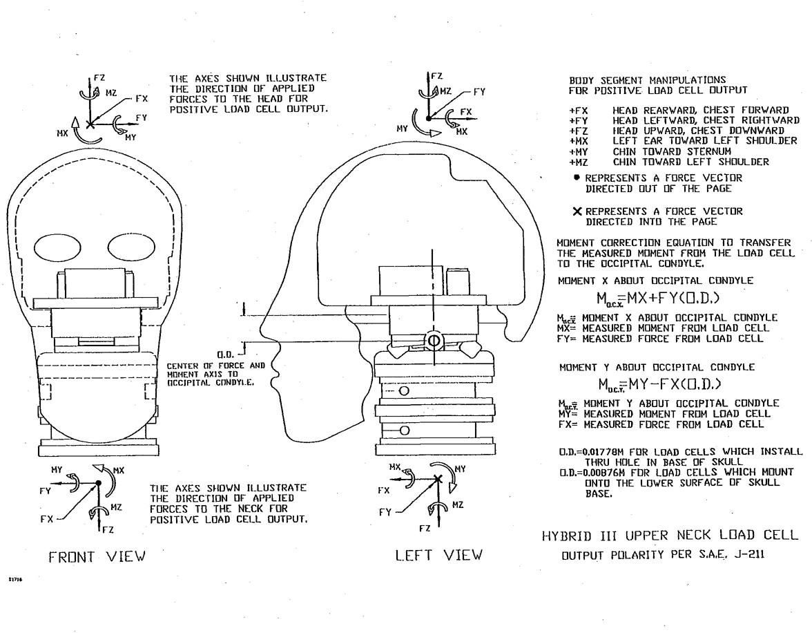
FIGURE 9—UPPER NECK LOAD CELL
11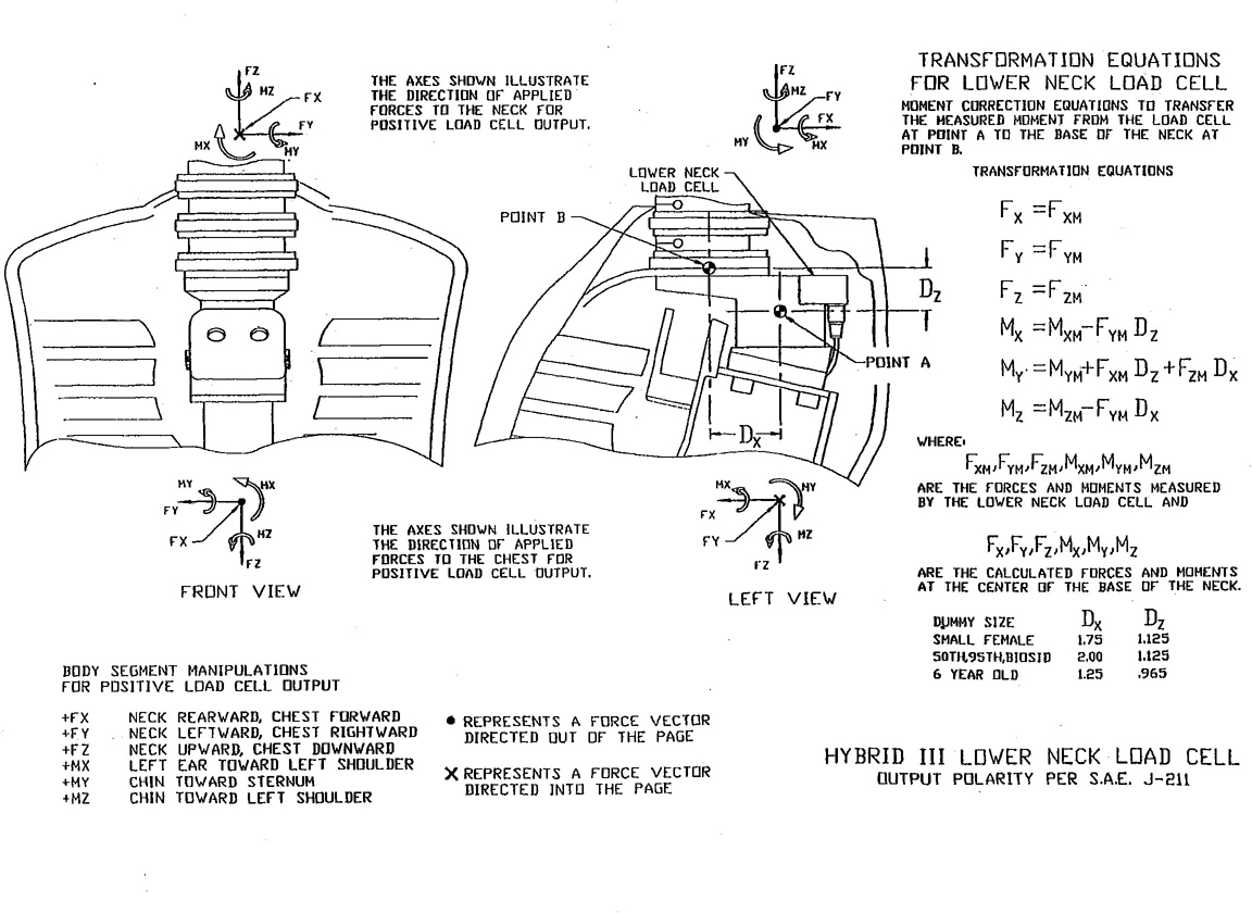
FIGURE 10—LOWER NECK LOAD CELL
12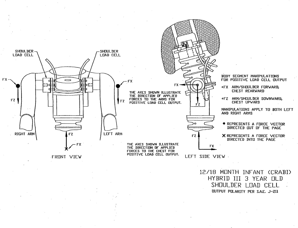
FIGURE 11—SHOULDER LOAD CELLS
13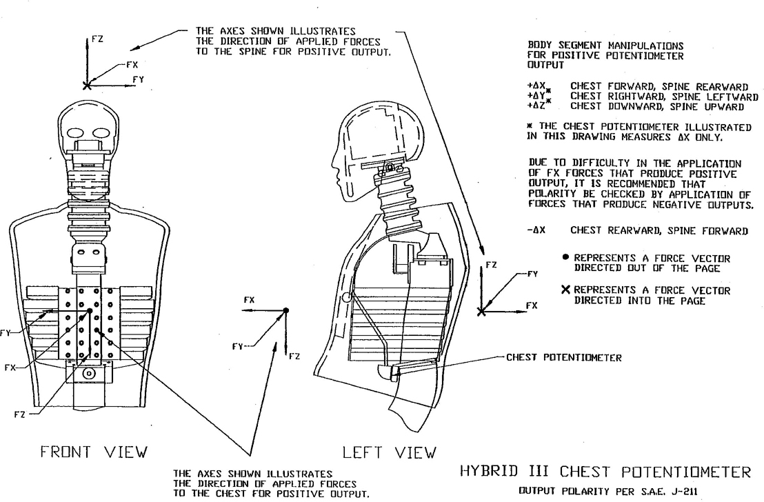
FIGURE 12—CHEST DEFLECTION TRANSDUCER
14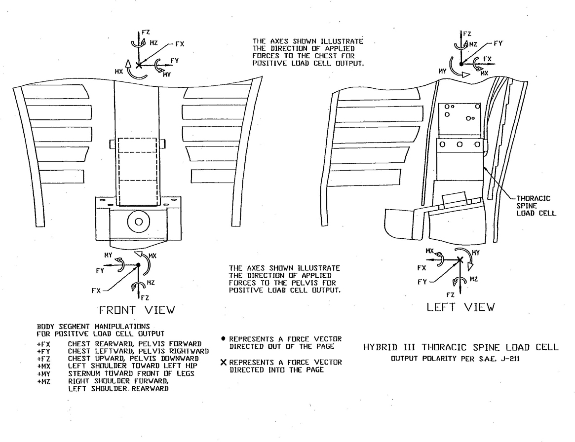
FIGURE 13—LOWER THORACIC SPINE LOAD CELL
15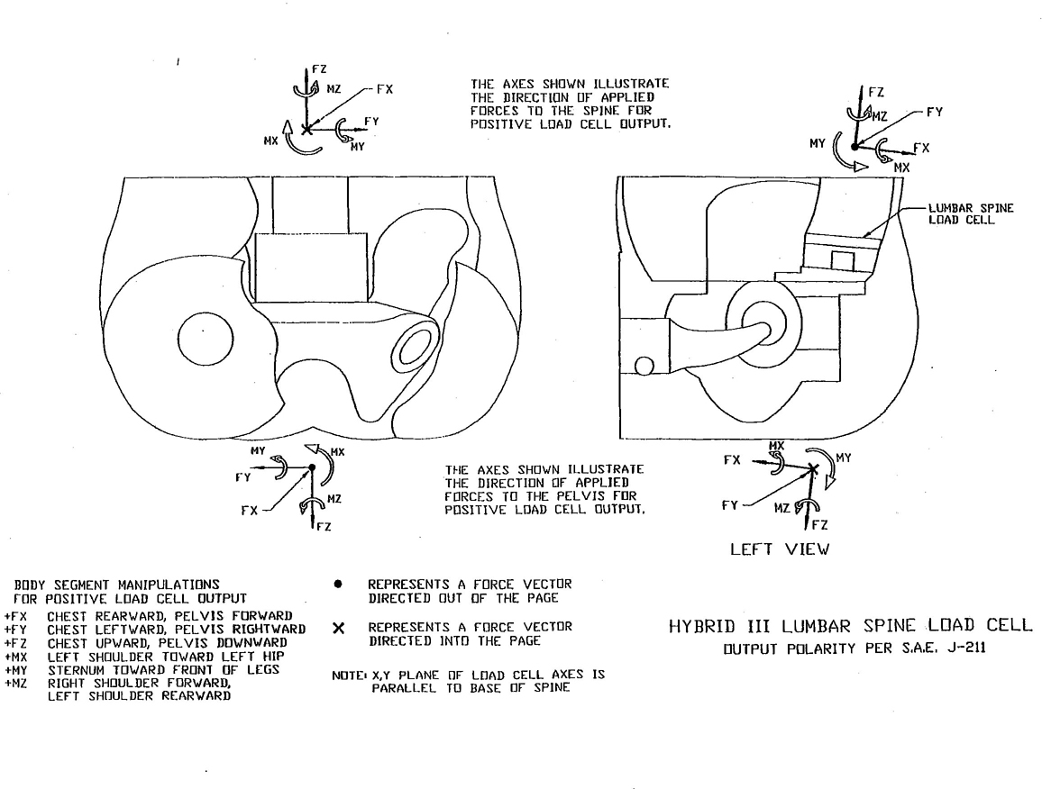
FIGURE 14—LOWER LUMBAR SPINE LOAD CELL
16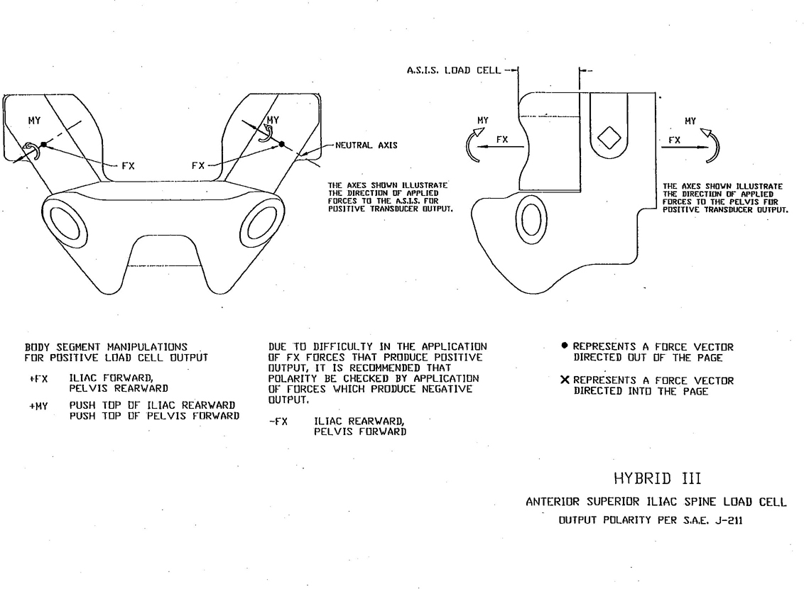
FIGURE 15—ILIAC LAMP BELT LOAD CELL
17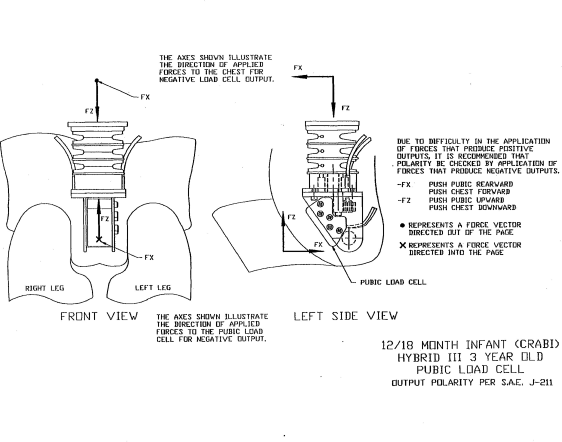
FIGURE 16—PUBIC LOAD CELL
18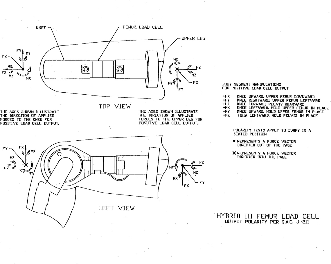
FIGURE 17—FEMUR LOAD CELL
19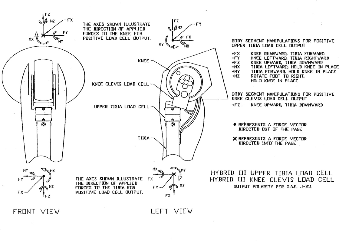
FIGURE 18—UPPER TIBIA AND KNEE CLEVIS LOAD CELLS
20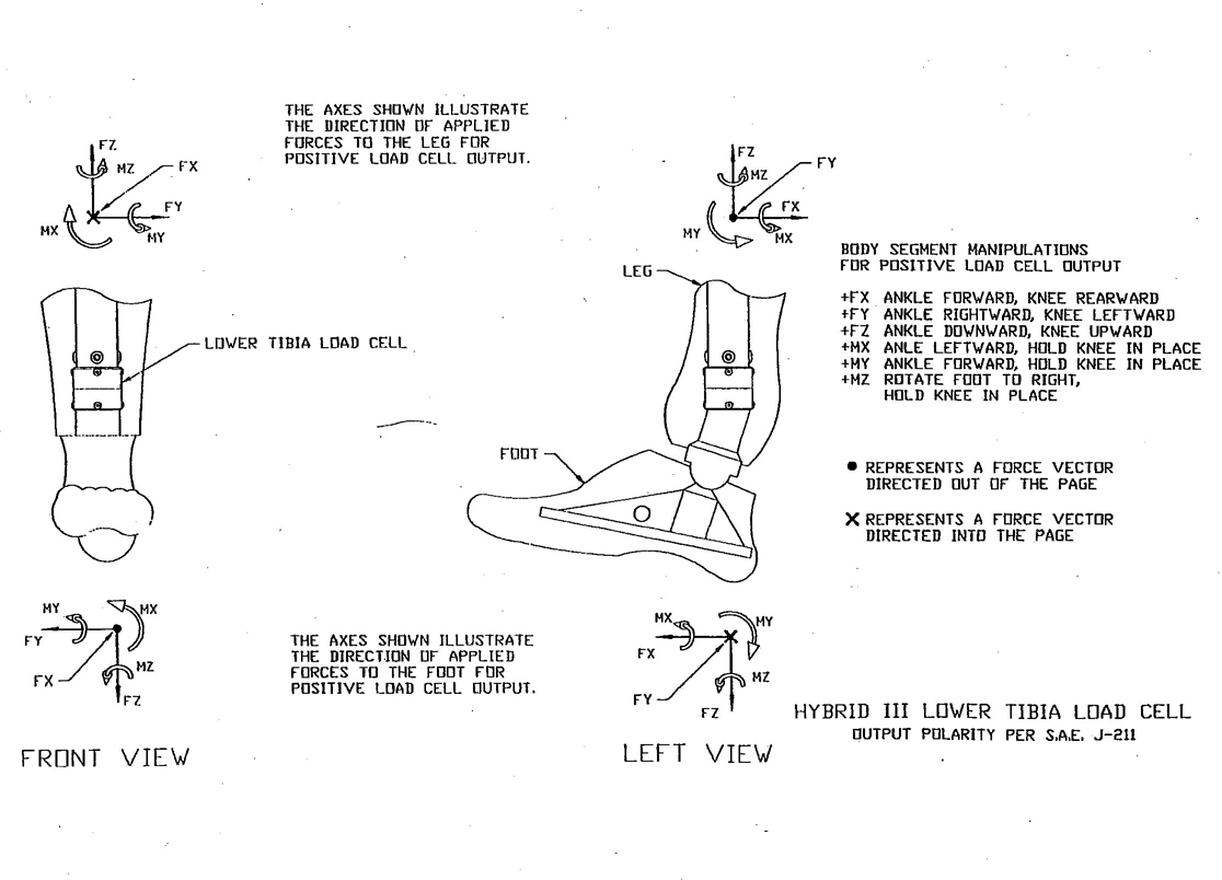
FIGURE 19—LOWER TIBIA LOAD CELL
21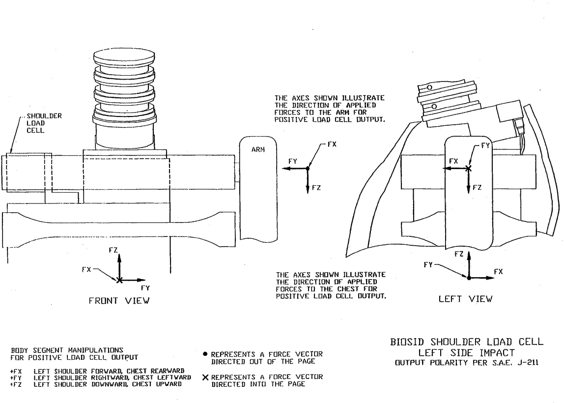
FIGURE 20—LT SHOULDER LOAD CELL
22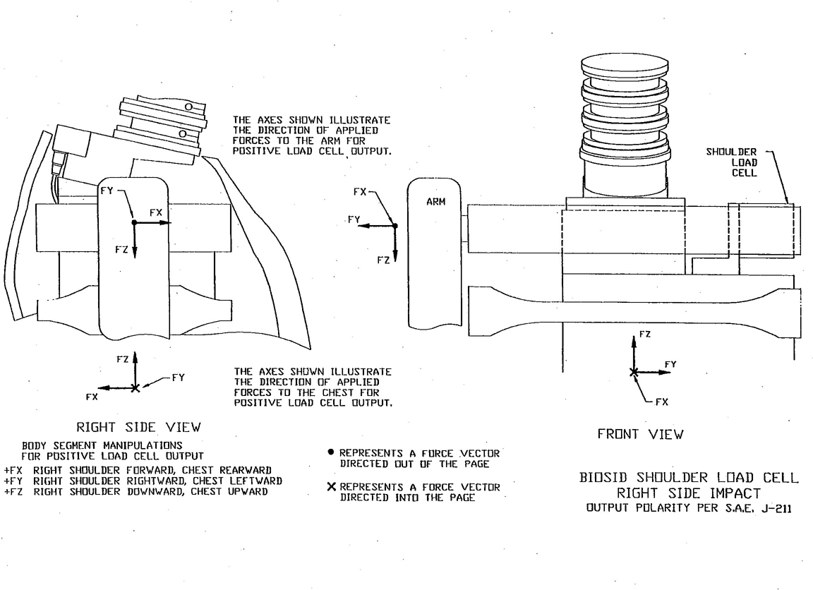
FIGURE 21—RT SHOULDER LOAD CELL
23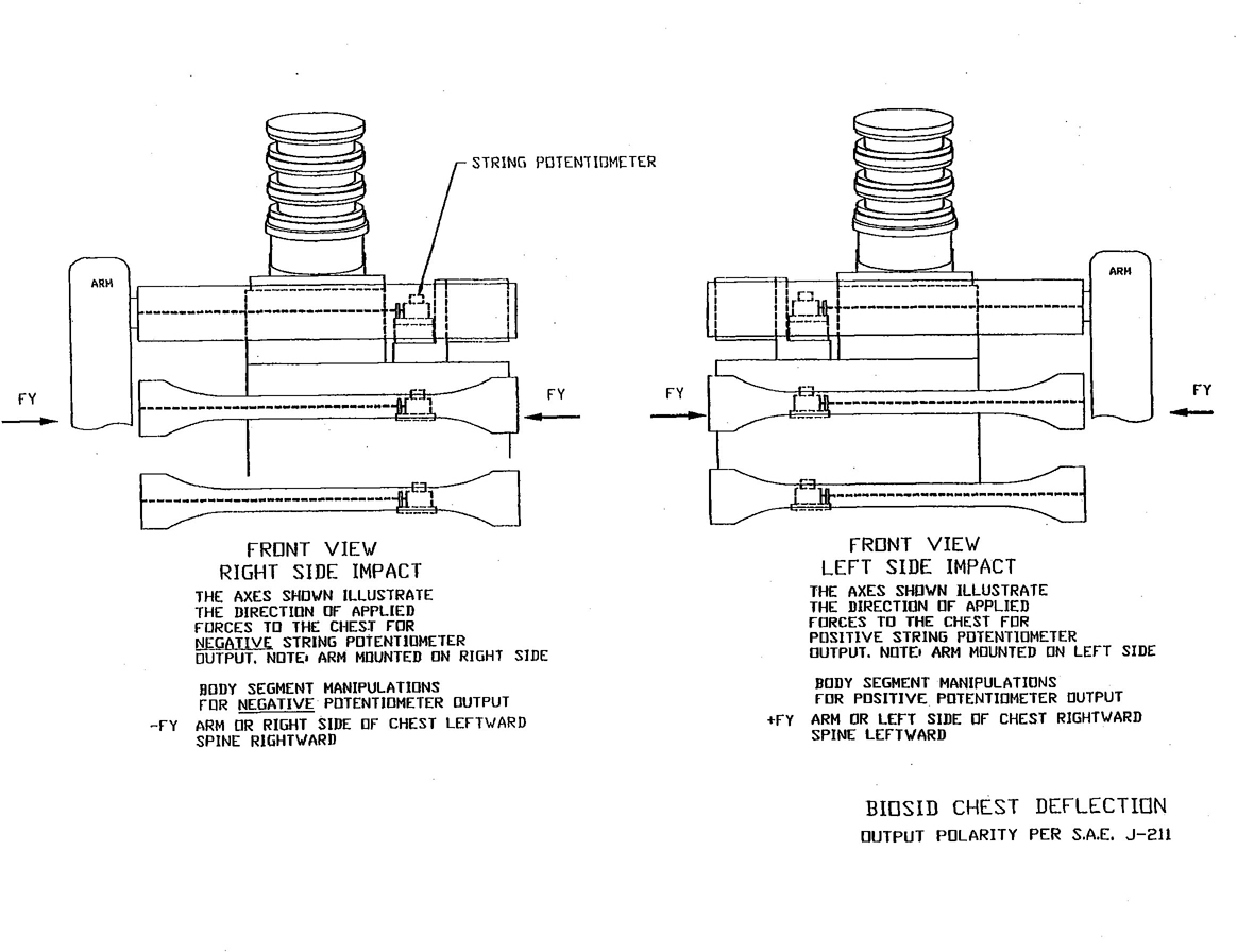
FIGURE 22—RIB DEFLECTION TRANSDUCER
24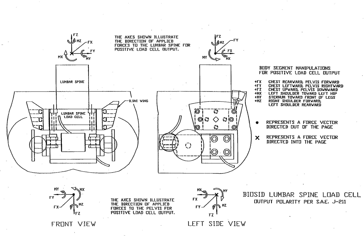
FIGURE 23—LOWER LUMBAR SPINE LOAD CELL
25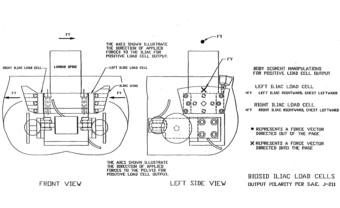
FIGURE 24—ILIAC WING LOAD CELL
26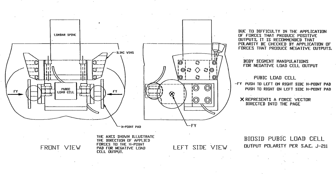
FIGURE 25—PUBIC LOAD CELL
27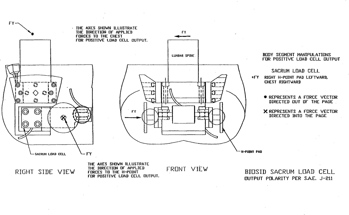
FIGURE 26—SACRUM LOAD CELL
28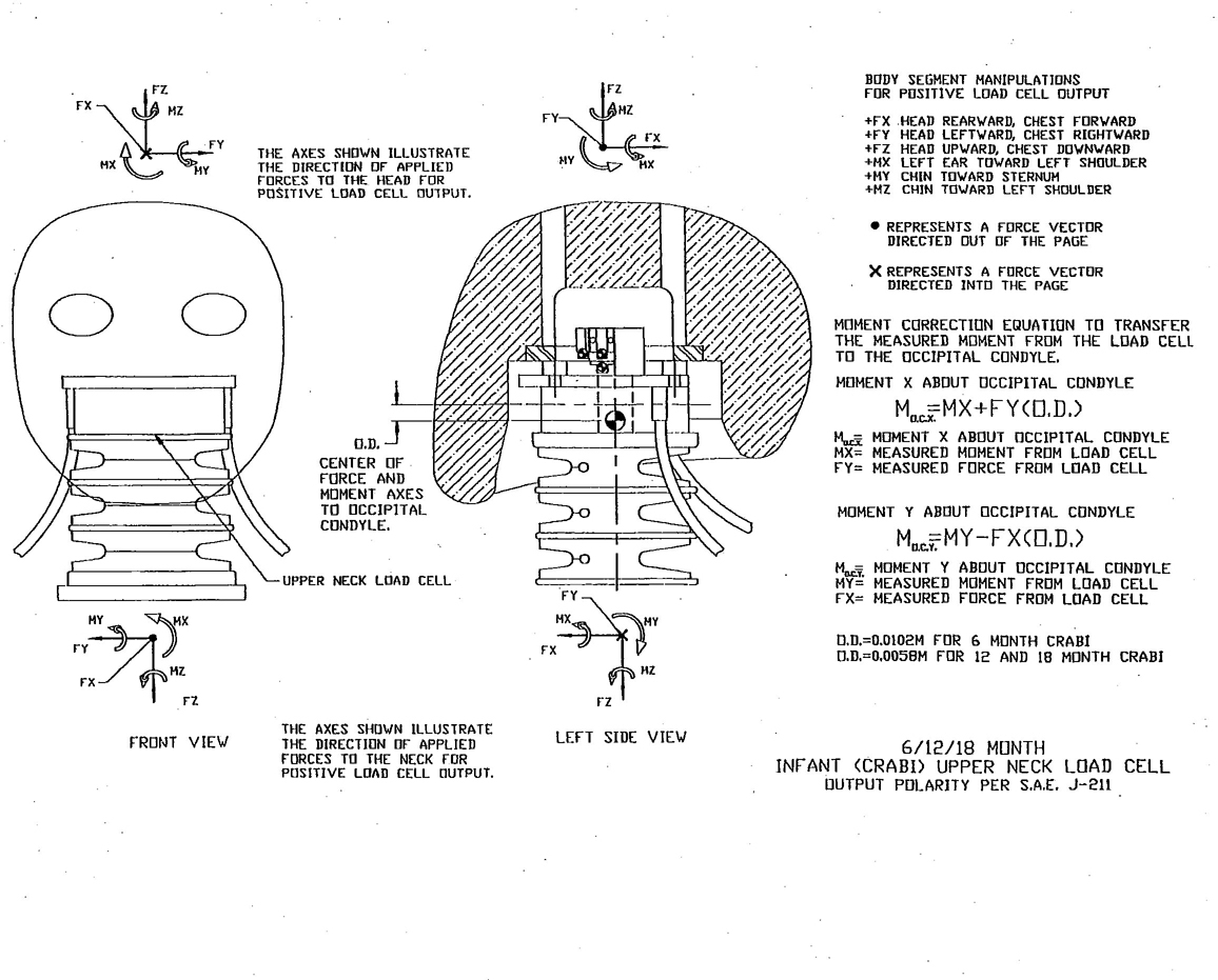
FIGURE 27—UPPER NECK LOAD CELL
29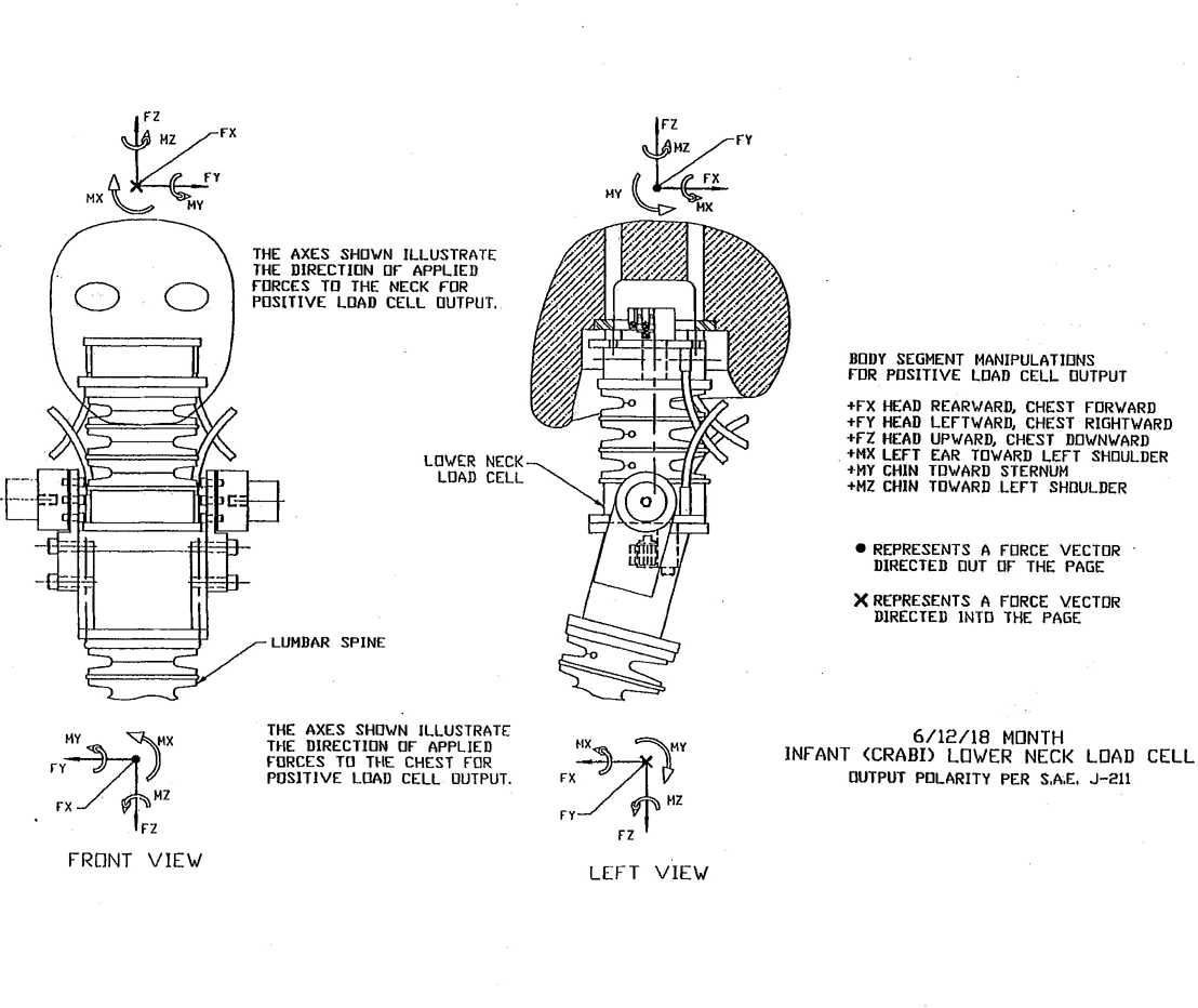
FIGURE 28—LOWER NECK LOAD CELL
30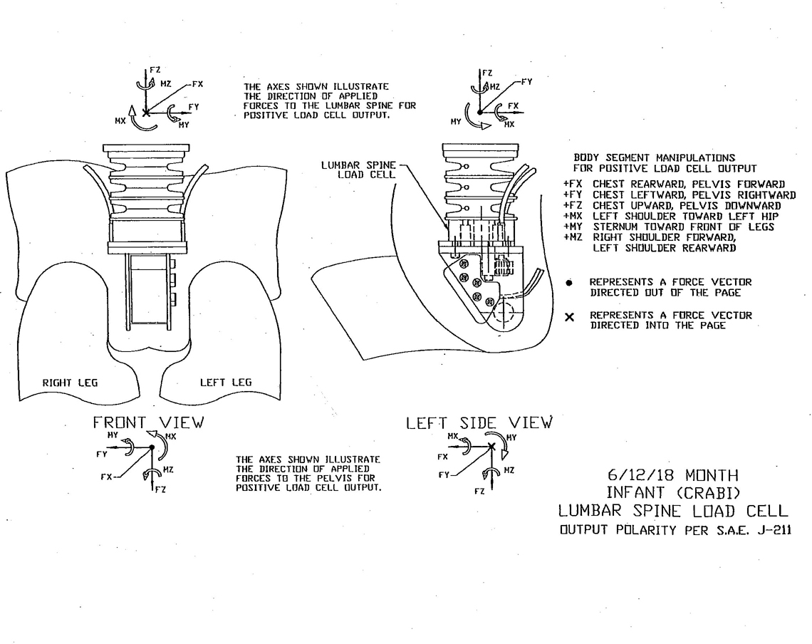
FIGURE 29—LOWER LUMBAR SPINE LOAD CELL
PREPARED BY THE SAE DUMMY TESTING EQUIPMENT SUBCOMMITTEE OF THE
SAE HUMAN BIOMECHANICS AND SIMULATION STANDARDS COMMITTEE
Rationale—Not Applicable.
Relationship of SAE Standard to ISO Standard—Not applicable.
Application—In order to compare test results obtained from different crash test facilities, standardized coordinate systems need to be defined for crash test dummies, vehicle structures, and laboratory fixtures. In addition, recorded polarities for various transducer outputs need to be defined relative to positive directions of the appropriate coordinate systems. This SAE Information Report describes the standardized sign convention and recorded output polarities for various transducers used in crash testing.
Reference Section
SAE J211—Instrumentation for Impact Test
SAE J670—Vehicle Dynamics Terminology
SAE J1594—Vehicle Aerodynamics Terminology
SAE J2052—Test Device Head Contact Duration Analysis
Developed by the SAE Dummy Testing Equipment Subcommittee
Sponsored by the SAE Human Biomechanics and Simulation Standards Committee
32