In order to promote public education and public safety, equal justice for all, a better informed citizenry, the rule of law, world trade and world peace, this legal document is hereby made available on a noncommercial basis, as it is the right of all humans to know and speak the laws that govern them.
SAE–J1703
ADOPTION NOTICE
SAE–J1703, “Brake Fluid, Motor Vehicles,” was adopted on October 3, 1994 for use by the Department of Defense (DoD). Proposed changes by DoD activities must be submitted to the DoD Adopting Activity: Commander, US Army Tank–Automotive Command, ATTN: AMSTA–GLC, Warren, MI 48397–5000. DoD activities may obtain copies of this standard from the Standardization Document Order Desk, 700 Robbins Avenue, Building 4D, Philadelphia, PA 19111–5094. The private sector and other Government agencies may purchase copies from the Society of Automotive Engineers, Inc., 400 Commonwealth Drive, Warrendale, PA 15096.
Custodians: Adopting Activity
Army - AT Army - AT
Navy - SH
Air Force - 99
FSC 2530
DISTRIBUTION STATEMENT A. Approved for public release; distribution is unlimited.
ii
SURFACE VECHILE STANDARD
Submitted for recongnition as an American National Standard
 J1703 REV. JAN95
Issued 1946-12
Revised 1995-01
Superseding J1703 JUN91
1. Scope—This SAE Standard covers motor vehicle brake fluids of the nonpetroleum type for use in the braking system of any motor vehicle such as a passenger car, truck, bus, or trailer. These fluids are not intended for use under arctic conditions. These fluids are designed for use in braking systems fitted with rubber cups and seals made from natural rubber (NR), styrene-butadiene rubber (SBR), or a terpolymer of ethylene, propylene, and a diene (EPDM).
2. References
2.1 Applicable Documents—The following publications form a part of this specification to the extent specified herein. The latest issue of SAE publications shall apply.
2.1.1 SAE PUBLICATION—Available from SAE, 400 Commonwealth Drive, Warrendale, PA 15096-0001.
SAE J527—Brazed Double Wall Low Carbon Steel Tubing
2.1.2 ASTM PUBLICATIONS—Available from ASTM, 1916 Race Street, Philadelphia, PA 19103-1187.
ASTM D 91—Test Method for Precipitation Number of Lubricating Oils
ASTM D 344—Method of Test for Relative Dry Hiding Power of Paints
ASTM D 445—Test Method for Kinematic Viscosity of Transparent and Opaque Liquids (and the Calculation of Dynamic Viscosity)
ASTM D 664—Test Method for Neutralization Number of Potentiometric Titration
ASTM D 1120—Method of Test for Boiling Point of Engine Antifreezes
ASTM D 1415—Method of Test for International Hardness of Vulcanized Natural Rubber and Synthetic Rubbers
ASTM D 2240—Method of Test for Indentation Hardness of Rubber and Plastics by Means of a Durometer
ASTM D 3182—Recommended Practice for Rubber-Materials, Equipment, and Procedures for Mixing Standard Compounds and Preparing Standard Vulcanized Sheets
ASTM D 3185—Methods for Rubber-Evaluation of SBR (Styrene-Butadiene Rubber) including Mixtures with Oil
ASTM E 1—Specification for ASTM Thermometers
ASTM E 260-73—Standard Recommended Practice for General Gas Chromatography Procedure
3. Material—The quality of the materials used shall be such that the resulting product will conform to the requirements of this standard and insure uniformity of performance.
SAE Technical Standards Board Rules provide that: “This report is published by SAE to advance the state of technical and engineering sciences. The use of this report is entirely voluntary, and its applicability and suitability for any particular use, including any patent infringement ansing therefrom, is the sole responsibility of the user.”
SAE reviews each technical report at least every five years at which time it may be reaffirmed, revised, or cancelled. SAE invites your written comments and suggestions.
Copyright 1995 Society of Automotive Engineers, Inc.
All rights reserved.
Printed in U.S.A.
14. Requirements
4.1 Equilibrium Reflux Boiling Point—Brake fluid when tested by the procedure specified in 5.1 shall have an equilibrium reflux boiling point not less than 205 °C (401 °F).
4.2 Wet Boiling Point—Brake fluid, when tested by the procedure specified in 5.2.2, shall have a wet boiling point of not less than 140 °C (284 °F).
4.3 Fluid Stability
4.3.1 HIGH TEMPERATURE STABILITY—When tested by the procedure specified in 5.3.1, the equilibrium reflux boiling point of the brake fluid shall not change by more than 5 °C (9 °F) increase or decrease.
4.3.2 CHEMICAL STABILITY—When tested by the procedure specified in 5.3.2, the test fluid mixture shall show no chemical reversion as evidenced by a change in recorded temperature of more than 5 °C (9 °F) increase or decrease.
4.4 Viscosity—Brake fluid when tested by the procedure specified in 5.4 shall have the following kinematic viscosities:
4.4.1 AT -40 °C (-40 °F)—Not more than 1800mm2/s (1800 cSt).
4.4.2 AT 100 °C (212 °F)—Not less than 1.5mm2/s (1.5 cSt).
4.5 pH Value—Brake fluid, when tested by the procedure specified in 5.5, shall have a pH value not less than 7.0, nor more than 11.5.
4.6 Corrosion—Brake fluid, when tested by the procedure specified in 5.6, shall not cause corrosion exceeding the limits shown in Table 1. The metal strips outside of the area where the strips are in contact shall neither be pitted nor roughened to an extent discernible to the naked eye, but staining or discoloration is permitted.
| Test Strip1 | RM No. | Max Permissible Weight Change, mg/cm2 of Surface |
|---|---|---|
| Tinned Iron | 6a | 0.2 |
| Steel | 7 | 0.2 |
| Aluminum | 8 | 0.1 |
| Cast Iron | 9 | 0.2 |
| Brass | 10 | 0.4 |
| Copper | 11 | 0.4 |
| Zinc | ISO-2 | 0.4 |
| 1 Obtainable from the Society of Automotive Engineers, Inc., 400 Commonwealth Drive, Warrendale, PA 15096-0001. | ||
The fluid-water mixtures at end of test shall show no jelling at 23 °C ± 5 °C (73 °F ± 9 °F.) No crystalline type of deposit shall form and adhere to either the glass jar walls or the surface of metal strips. The fluid-water mixture shall contain no more than 0.10% sediment by volume. The fluid-water mixture shall have a pH value of not less than 7.0, nor more than 11.5.
The rubber cup at end of test shall show no disintegration, as evidenced by blisters or sloughing indicated by carbon black separation on the surface of the rubber cup. The hardness of the rubber cup shall not decrease by more than 15 degrees and the base diameter shall not increase by more than 1.4mm (0.055 in).
4.7 Fluidity and Appearance at Low Temperatures
4.7.1 AT −40 °C (−40 °F)—When brake fluid is tested by the procedure specified in 5.7.1, the fluid shall show no stratification, sedimentation, or crystalization. Upon inversion of sample bottle, the air bubble shall travel to the top of the fluid in not more than 10 s. Cloudiness is permissible, but on warming to room temperature 23 °C ± 5 °C (73 °F ± 9 °F), the fluid shall regain its original uniformity, appearance, and clarity.
4.7.2 AT −50 °C (−58 °F)—When brake fluid is tested by the procedure specified in 5.7.2, the fluid shall show no stratification, sedimentation, or crystallization. Upon inversion of sample bottle, the air bubble shall travel to the top (73 °F ± 9 °F), the fluid shall regain its original uniformity, appearance, and clarity.
4.8 Evaporation—When brake fluid is tested by the procedure specified in 5.8, loss by evaporation shall not exceed 80% by weight. Residue from the brake fluid after evaporation shall contain no precipitate that remains gritty or abrasive when rubbed with the fingertip. Residue shall have a pure point below −5 °C (+23 °F).
4.9 Water Tolerance
4.9.1 AT −40 °C (−40 °F)—When brake fluid is tested by the procedure specified in 5.9.1, the black contrast lines on a hiding power chart shall be discernible when viewed through the fluid in the centrifuge tube. The fluid shall show no stratification or sedimentation. Upon inversion of the centrifuge tube, the air bubbles shall travel to the top of the fluid in not more than 10 s.
4.9.2 AT 60 °C (140 °F)—When brake fluid is tested by the procedure specified in 5.9.2, the fluid shall show no stratification, and sedimentation shall not exceed 0.05% by volume after centrifuging when fluid is tested for qualification, or shall not exceed 0.15% by volume for a commercial packaged fluid.
4.10 Compatibility
4.10.1 AT −40 °C (−40 °F)—When brake fluid is tested by the procedure specified in 5.10.1, the black contrast lines on a hiding power chart shall be discernible when viewed through the fluid in the centrifuge tube. The fluid shall show no stratification or sedimentation.
4.10.2 AT 60 °C (140 °F)—When brake fluid is tested by the procedure specified in 5.10.2, the fluid shall show no stratification, and sedimentation shall not exceed 0.05% by volume after centrifuging.
4.11 Resistance to Oxidation—Brake fluid, when tested by the procedure specified in 5.11, shall not cause the metal strips outside the areas in contact with the tinfoil to be pitted or roughened to an extent discernible to the naked eye, but staining or discoloration is permitted. No more than a trace of gum shall be deposited on the test strips outside of the areas in contact with the tinfoil. The aluminum strips shall not decrease in weight by more than 0.05mg/cm2 and the cast iron strips shall not decrease in weight by more than 0.3mg/cm2.
34.12 Effect on Rubber
4.12.1 Rubber brake cups subjected to brake fluid, as specified in 5.12.1, shall show no increase in hardness, shall not decrease in hardness by more than 10 points, and shall show no disintegration as evidenced by blisters or sloughing indicated by carbon black separation on the surface of the rubber cup. The increase in the diameter of the base of the cups shall not be less than 0.15mm (0.006 in), nor more than 1.4mm (0.055 in).
4.12.2 Rubber brake cups subjected to brake fluid, as specified in 5.12.2, shall show no increase in hardness, shall not decrease in hardness by more than 15 points, and shall show no disintegration as evidenced by blisters or sloughing indicated by carbon black separation on the surface of the rubber cup. The increase in the diameter of the base of the cups shall not be less than 0.15mm (0.006 in), nor more than 1.4mm (0.055 in).
4.12.3 Rubber slab stock subjected to brake fluid, as specified in 5.12.3, shall show no increase in hardness, shall not decrease in hardness by more than 10 points, and shall show no disintegration as evidenced by blisters or sloughing indicated by carbon black separation on the surface of the test specimens. The test specimens shall not decrease in volume and the increase in volume shall not exceed 10%.
4.12.4 Rubber slab stock subjected to brake fluid, as specified in 5.12.4, shall show no increase in hardness, shall not decrease in hardness by more than 15 points, and shall show no disintegration as evidenced by blisters or sloughing indicated by carbon separation on the surface of the test specimens. The test specimens shall not decrease in volume and the increase in volume shall not exceed 10%.
4.13 Stroking Test—Brake fluid, when tested by the procedure specified in 5.13, shall meet the following performance requirements:
4.13.1 Metal parts shall not show corrosion as evidenced by pitting to an extent discemible to the naked eye, but staining or discoloration shall be permitted.
4.13.2 The initial diameter of any cylinder or piston shall not change by more than 0.13mm (0.005 in) during test.
4.13.3 Rubber cups-shall not decrease in hardness by more than 15 degrees and shall not be in an unsatisfactory operating condition as evidenced by excessive amounts of scoring, scuffing, blistering, cracking, chipping (heel abrasion), or change in shape from original appearance.
4.13.4 The base diameter of the rubber cups shall not increase by more than 0.9mm (0.035 in).
4.13.5 The average lip diameter interference set of the rubber cups shall not be greater than 65%.
4.13.6 During any period of 24 000 strokes, the volume loss of fluid shall be not more than 36mL.
4.13.7 The cylinder pistons shall not freeze nor function improperly throughout the test.
4.13.8 The volume loss of fluid during the 100 strokes at the end of the test shall not be more than 36mL.
4.13.9 The fluid at the end of the test shall not be in an unsatisfactory operating condition as evidenced by sludging, jelling, or abrasive grittiness, and sedimentation shall not exceed 1.5% by volume after centrifuging.
4.13.10 No more than a trace of gum shall be deposited on brake cylinder walls or other metal parts during test. Brake cylinder shall be free of deposits which are abrasive or which cannot be removed when rubbed with a cloth wetted with isopropanol.
45. Test Procedures
5.1 Equilibrium Reflux Boiling Point—Determine the equilibrium reflux boiling point of the fluid by ASTM D 1120 with the following exceptions:
5.1.1 APPARATUS
5.1.1.1 4.4 Thermometer—ASTM E 1, 76mm immersion, calibrated. Use ASTM 3C or 3F thermometer. For fluids boiling below 300°C (572°F), ASTM 2C or 2F thermometer may be used.
5.1.1.2 4.5 Heat Source—Use a suitable variac-controlled 100mL heating and reflux rates. (Supplier: GLAS COL Apparatus Co., Terre Haute, IN. Serial number. 135464. 230 W, 135 V [max]).
5.1.1.3 Preparation of Apparatus—6.4 Thoroughly clean and dry all glassware before use. Attach the flask to the condenser. Place the mantle under the flask and support it with a suitable ring clamp and laboratory type stand, holding the whole assembly in place by a clamp.
NOTE—Place the whole assembly in an area free from drafts or other types of sudden temperature changes.
5.1.2 PROCEDURE—7.1 When everything is in readiness, turn on the condenser water and apply heat to the flask at such a rate that the fluid is refluxing in 10 min ± 2 min at a rate in excess of 1 drop/s.
Immediately adjust heat input to obtain a specified equilibrium reflux rate of 1 to 2 drops/s over the next 5 min ± 2 min period. Maintain a timed and constant equilibrium reflux rate of 1 to 2 drops/s for an additional 2 min; record the average value of four temperature readings taken at 30s intervals as the equilibrium reflux boiling point.
5.1.2.1 205 and 232°C (401 and 450 °F) Fluids—Report the boiling point to the nearest degree Celsius (Fahrenheit). Duplicate runs which agree within 1°C(2 °F) are acceptable for averaging (95% confidence level).
5.1.3 REPEATABILITY (SINGLE ANALYST)—The standard deviation of results (each the average of duplicates), obtained by the same analyst on different days, has been estimated to be 0.4 °C (3.02 °F) at 72 degrees of freedom. Two such values should be considered suspect (95% confidence level) if they differ by more than 1.5 °C (2.5 °F).
5.1.4 REPRODUCIBILITY (MULTILABORATORY)—The standard deviation of results (each the average of duplicates), obtained by analysts in different laboratories, has been estimated to be 1.8 °C (3.02°F) at 17 degrees of freedom. Two such values should be considered suspect (95% confidence level) if they differ by more than 5 °C (9 °F).
5.1.5 288 °C (550 °F) FLUID—Report the boiling point to the nearest degree Celsius (Fahrenheit). Duplicate runs which agree within 3 °C (5 °F) are acceptable for averaging (95% confidence level).
5.1.6 REPEATABILITY (SINGLE ANALYST)—The standard deviation of results (each the average of duplicates), obtained by one analyst on different days, has been estimated to be 1.3 °C (2.38 °F) at 34 degrees of freedom. Two such values should be considered suspect (95% confidence level) if they differ by more than 4 °C (7 °F).
5.1.7 REPRODUCIBILITY (MULTILABORATORY)—The standard deviation of results (each the average of duplicates), obtained by analysts in different laboratories, has been estimated to be 3.5 °C(6.44 °F) at 15 degrees of freedom. Two such values should be considered suspect (95% confidence level) if they differ by more than 10.5 °C (19 °F).
55.2 Wet Boiling Point
5.2.1 HUMIDIFICATION PROCEDURE—Lubricate the ground-glass joint of a 250mm (9.89 in) I.D. bowl-form desiccator having matched tubulated glass cover and fitted with a No. 8 rubber stopper. Pour 450mL ± 10mL (15.22 oz ± 0.34 oz) of distilled water into the desiccator and insert a perforated porcelain plate (Coors No. 60456 or equivalent). Immediately place a second open RM-49 corrosion test jar containing 350mL ± 5mL of TEGME control fluid at the start of exposure shall have been adjusted to 0.50% ± 0.05% by weight (Karl Fischer analysis or equivalent). Replace desiccator cover and insert at once into an ASTM E 145, Type II A, forced ventilation oven set at 50 °C ± 1°C (122 °F ± 1.8 °F).
Periodically, during oven humidification, remove the rubber stopper from the desiccator and, using a long needle hypodermic syringe, quickly sample the control fluid and determine its water content. When the water content of the control fluid has reached 3.70% ± 0.05% by weight, remove the desiccator from the oven and seal the test jar promptly using a screw-cap lid (RM-63). Allow the sealed jar to cool for 60 to 90 min at 23 °C ± 5 °C (73.4 °F ± 9 °F).
5.2.2 WET BOILING POINT PROCEDURE—Humidity the fluid as described in 5.2.1 and determine the boiling point as described in 5.1.
5.3 Fluid Stability
5.3.1 HIGH TEMPERATURE STABILITY—Heat a new sample of the original test brake fluid to a temperature of 185 °C ± 2 °C (365 °F ± 3.6 °F) by the procedure specified in 5.1 and maintain at that temperature for 2h. Then determine the boiling point of this brake fluid as specified in 5.1. The difference between this observed boiling point and that previously determined in 5.1 shall be considered as the change in boiling point of the brake fluid.
5.3.2 CHEMICAL STABILITY—Mix 30mL of fluid with 30mL of SAE Compatibility Fluid described in Appendix B (RM-66-04). Determine the equilibrium reflux boiling point of this fluid mixture by use of the test apparatus specified in 5.1, applying heat to the flask at such a rate that the fluid is refluxing in 10 min ± 2 min at a rate in excess of 1 drop/s. The reflux rate shall not exceed 5 drop/s. Record the maximum fluid temperature observed during the first minute after the fluid begins refluxing at a rate in excess of 1 drop/s. Over the next 15 min ± 1 min, adjust and maintain the rate of reflux to 1 to 2 drops/s. Maintain a timed and constant equilibrium reflux rate of 1 to 2 drops/s for an additional 2 min; record the average value of four temperature readings taken at 30s intervals as the final equilibrium reflux boiling point. Chemical reversion is evidenced by the decrease in temperature between the maximum fluid temperature recorded and the final equilibrium reflux boiling point.
5.4 Viscosity—Determine the kinematic viscosity of the fluid by ASTM D 445.
5.4.1 Report the viscosity to the nearest mm2/s (centistoke). Duplicate runs which agree within 1.2% relative are acceptable for averaging (95% confidence level).
5.4.2 REPEATABILITY (SINGLE ANALYST)—The coefficient of variation of results (each the average of duplicates), obtained by the same analyst on different days has been estimated to be 0.4% at 47 degrees of freedom. Two such values should be considered suspect (95% confidence level) if they differ by more than 1.2%
5.4.3 REPRODUCIBILITY (MULTILABORATORY)—The coefficient of variation of results (each the average of duplicates), obtained by analysts in different laboratories, has been estimated to be 1% at 15 degrees of freedom. Two such values should be considered suspect (95% confidence level) if they differ by more than 3%
65.5 pH Value—Mix the fluid with an equal volume of a mixture of 80% ethanol and 20% distilled water neutralized to a pH of 7.0. Determine the pH of the resulting solution electrometrically at 23 °C ± 5 °C (73.4 °F ± 9°F), using a pH meter equipped with a calibrated full range (0 to 14) glass electrode and a calomel reference electrode, as specified in ASTM D 664.
5.6 Corrosion—Prepare two sets of strips from each of the metals listed in Table 1, each strip having a surface area of 25 cm2 ± 5 cm2 (approximately 8 cm long, 1.3 cm wide, and not more than 0.6 cm thick). Drill a hole between 4 and 5mm in diameter and about 6mm from one end of each strip. With the exception of the tinned iron strips, clean the strips by abrading them on all surface areas with 320A waterproof carborundum paper (RM-29) and isopropanol or ethanol until all surface scratches, cuts, and pits are removed from the strips, using a new piece of carborundum paper for each different type of metal. Wash the strips, including the tinned iron, with isopropanol or ethanol and dry the strips with a clean lint-free cloth and place strips in a clean lint-free cloth and strips in a desiccator containing desiccant maintained at 23 °C ± 5 °C (73.4 °F ± 9 °F) for at least 1h. Handle the strips with clean forceps after polishing to avoid fingerprint contamination.
Weigh each strip to the nearest 0.1 mg and assemble each set of strips on an uncoated steel bolt (RM-61) in the order tinned iron, steel, aluminium, cast iron, brass, copper, and zinc, so that the strips are in electrolytic contact. Bend the strips, other than cast iron, so that there is a separation of at least 3mm between adjacent strips for a distance of about 6 cm from the end of the strips. Immerse strip assemblies in isopropanol or ethanol to eliminate fingerprints and then handle only with clean forceps.
Measure the base diameter of two standard SBR cups (RM-3a) described in Appendix C, using an optical comparator or micrometer to the nearest 0.02mm (0.001 in) along the centerline of the SAE and rubber type identifications and at right angles to this centerline. Take the measurements within 0.4mm (0.015 in) of the bottom edge and parallel to the base of the cup. Discard any cup if the two measured diameters differ by more than 0.08mm (0.003 in). Average the two readings of each cup. Support the rubber cup on a rubber anvil or cylinder having a flat circular top surface of at least 19mm in diameter, a thickness of at least 9mm, and a hardness within 5 IRHD of the hardness of the rubber test cup. Determine the hardness of each cup thus supported by the procedure specified in ASTM D 1415 using the Standard Tester.
NOTE—ASTM D 2240 may be used for quality control and routine tests when a type A durometer is equipped with a fixture for keeping the plane of the pressure foot on the durometer parallel to the plane of the cup face during measurement.
Obtain two straight-sided round glass jars1 (RM-49) having a capacity of approximately 475 mL and inner dimensions of approximately 100mm in height and 75mm in diameter.
To the RM-49 corrosion test jar, apply four wrappings of ¾ in Teflon tape around the jar threads allowing a 1/8 in height above the top of the jar. Place one rubber cup with lip edge facing up, in each of the two glass jars. Use only tinned steel lids vented with a hole 0.8mm ± 0.1mm in diameter (RM-64).
Insert a metal strip assembly inside each cup with the bolted end in contact with the concavity of the cup and the free end extending upward in the jar. Mix 760 mL of fluid with 40 mL of distilled water.
1 Obtainable from the Society of Automotive Engineers, Inc., 400 Commonwealth Drive Warrendale, PA 15096-0001.
7Add 400 mL of the mixture to cover the metal strip assembly in each jar to a depth of approximately 10mm above the tops of the strips. Tighten the lids and place the jars in an oven maintained at 100 °C ± 2 °C (212 °F ± 3.6 °F) for 120h ± 2h. Allow the jars to cool at 23 °C ± 5 °C (73.4 °F ± 9 °F) for 60 to 90 min. Immediately following the cooling period, remove the metal strips from the jars by use of a forceps, removing loose adhering sediment by agitation of the metal strip assembly in the fluid in jar. Examine test strips and test jars for adhering crystalline deposit, disassemble the metal strips, removing adhering fluid by flushing with water, and clean individual strips by wiping with a cloth wetted with isopropanol or ethanol. Examine the strips for evidence of corrosion and pitting. Place strips in a desiccator containing a desiccant maintained at 23 °C ± 5 °C (73.4 °F ± 9 °F) for at least 1h. Weigh each strip to the nearest 0.1 mg. Determine the difference in weight of each metal strip and divide the difference by the total surface area of the metal strip and divide the difference by the total surface area of the metal strip measured in square centimeters. Average the measured quantities of the duplicates. In the event of a marginal pass on inspection, or of a failure in only one of the duplicates, another set of duplicate test samples shall be run. Both repeat samples must meet all the requirements of 4.6.
Immediately following the cooling period, remove the rubber cups from the jars by use of a forceps, removing loose adhering sediment by agitation of the cup in the fluid in jar. Rinse cups in isopropanol or ethanol and air dry cups. Examine the cups for evidence of sloughing, blisters, and other forms of disintegration. Measure the base diameter and hardness of each cup within 15 min after removal from the fluid.
Examine the fluid-water mixture in the jars for jelling. Agitate the fluid in jars to suspend and uniformly disperse sediment and transfer a 100 mL portion of this fluid to an ASTM cone-shaped centrifuge tube and determine percent sediment as described in 5.2 of ASTM D 91. Measure the pH value of the corrosion test fluid by the procedure specified in 5.5.
5.7 Fluidity and Appearance at Low Temperature
5.7.1 AT −40 °C (−40 °F)—Place 100 mL of the test fluid in a glass sample bottle2 (RM-59a) having a capacity of approximately 125 mL, an outside diameter of 37mm ± 0.5mm, and an overall height of 165mm ± 3mm. Stopper or cap the bottle tightly and place in a cold bath maintained at -40°C (-40 °F ± 3.6 °F) for 144h ± 4h. Remove the bottle from the bath, quickly wipe the bottle with a clean lint-free cloth saturated with isopropanol or ethanol, and examine the fluid for evidence of stratification, sediment, or crystals. Invert the bottle and determine the number of seconds required for the air bubble to travel to the top of the fluid. Allow the fluid to warm to room temperature 23 °C ± 5 °C (73 °F ± 9 °F); if necessary, allow to stand for as long as 4h. Examine the fluid for clarity and appearance by comparing it to an original sample of the test fluid in an identical container.
5.7.2 AT −50 °C (−58 °F)—Place 100mL of fluid in a glass sample bottle (same as in −40 °C test above). Stopper or cap the bottle tightly and place in a cold bath maintained at −50 °C ± 2 °C (−58 °F ± 3.6 °F) for 6h ± 0.2h. Remove the bottle from the bath, quickly wipe the bottle with a clean lint-free cloth saturated with isopropanol or ethanol, and examine the fluid for evidence of stratification, sediment, or crystals. Invert the bottle and determine the number of seconds required for the air bubble to travel to the top of the fluid. Allow the fluid to warm to room temperature 23 °C ± 5°C (73 °F ± 9 °F); if necessary, allow to stand for as long as 4h. Examine the fluid for clarity and appearance by comparing it to a sample of the original test fluid in an identical container.
5.8 Evaporation—Obtain the tare weight of four covered Petri dishes of approximately 100mm in diameter and 15mm high, weighing with cover in place to the nearest 0.01 g. Place approximately 25mL of fluid in each of the four tared Petri dishes, replace proper covers, and reweigh to the nearest 0.01 g. Determine the weight of fluid from the difference in weights of filled and empty dishes.
2 Obtainable from the Society of Automotive Engineers, Inc., 400 Commonwealth Drive, Warrendale, PA 15096-0001.
8Place the dishes inside the inverted covers in a top vented gravity convection oven at 100 °C ± 2 °C (212 °F ± 3.6 °F) and maintain this temperature for a total of 168h ± 2h.
Remove the dishes from the oven. Allow to cool to 23 °C (73.4 °F ± 9 °F) with covers on and weigh each dish. Calculate the percentage of fluid evaporated from each dish. Average the percentage evaporated from all four dishes to determine the loss by evaporation.
Examine the residue in the dishes at the end of 1h at 23 °C ± 5 °C (73.4 °F ± 9 °F). Rub any sediment with the fingertip to determine grittiness or abrasiveness.
Combine the residue from the four dishes in an oil sample bottle (RM-59a), store in a vertical position at -5 °C ± 1 °C (23 °F ± 1.8 °F) for 60 min, then remove quickly and turn to the horizontal. The residue must flow at least 5mm (0.2 in) along tube wall within 5 s.
5.9 Water Tolerance
5.9.1 AT −40 °C (−40 °F)—Four 100mL of fluid which has been humidified according to 5.2.1 into an ASTM cone-shaped centrifuge tube described in 3(a) in ASTM D 91. Stopper the tube with a cork and place in a cold both maintained at −40 °C ± 2 °C (−40 °F ± 3.6 °F) for 22h ± 2h. Remove the centrifuge tube from the bath, quickly wipe the tube with a clean lint-free cloth saturated with isopropanol or ethanol, determine the transparency of the fluid by placing the tube against a hiding power test chart3 (RM-28) and observing the clarity of the contrast lines on the chart when viewed through the fluid. Examine the fluid for evidence of stratification and sedimentation. Invert the tube and determine the number of seconds required for the air bubble to travel to the top of the fluid. (The air bubble shall be considered to have reached the top of the fluid when the top of the bubble reaches the 2mL graduation of the centrifuge tube).
5.9.2 AT 60 °C (140 °F)—Place the centrifuge tube from 5.9.1 in an oven maintained at 60 °C ± 2 °C (140 °F ± 3.6 °F) for 22h ± 2h. Remove the tube from the oven and immediately examine the contents for evidence of stratification. Determine percent sediment by volume as described in 5.2 of ASTM D 91.
5.10 Compatibility
5.10.1 AT −40 °C (−40 °F)—Mix 50mL of fluid with 50mL of SAE Compatibility Fluid described in Appendix B (RM-66-04) and pour this mixture into an ASTM cone-shaped centrifuge tube described tube in 3(a) in ASTM D 91 and stopper with a cork. Place centrifuge tube for 22h ± 2h in a bath maintained at −40 °C ± 2 °C (−40 °F ± 3.6 °F). Remove the centrifuge tube from the bath, quickly wipe the tube with a clean lint-free cloth saturated with Isopropanol or ethanol, determine the transparency of the fluid by placing the tube against a hiding power test chart3 (RM-28) and observing the clarity of the contrast lines on the chart when viewed through the fluid. Examine the fluid for stratification and sedimentation.
5.10.2 AT 60 °C (140 °F)—Place the centrifuge tube from 5.10.1 in an oven at 60 °C ± 2 °C (140 °F ± 3.6 °F) for 22h ± 2h. Remove the tube from the oven and immediately examine the contents for evidence of stratification. Determine percent sediment by volume as described in 5.2 of ASTM D 91.
3 A suitable hiding power chart as described in ASTM D 344, Method of Test for Relative Dry Hiding Power of Paints, published by the American Society for Testing and Materials, or in Method 4112 of Federal Test Method Standard No. 141, is obtainable from the Society of Automotive Engineers, Inc., 400 Commonwealth Drive, Warrendale, PA 15096-0001.
95.11 Resistance to Oxidation—Prepare two sets of aluminum and cast iron test strips (as listed in Table 1) by the procedure specified in 5.6. Weigh each strip to the nearest 0.1mg and assemble a strip of each metal on an uncoated steel bolt (RM-62), separating the strips at each end with a piece of tinfoil4 (RM-27) (99.5% tin, 0.5%lead, max) approximately 12mm square and between 0.02 and 0.06mm in thickness.
Place 30mL ± 1mL of fluid in a small glass bottle approximately 120mL in capacity. Add 60mg ± 2mg of reagent grade benzoyl peroxide and 1.5mL ± 0.05mL distilled water to bottle. Stopper the bottle and shake the contents, avoiding getting the solution on the stopper. Place bottle in an oven at 70°C ± 2°C (158 °F ± 3.6 °F) for 120 min ± 10 min, shaking every 15 min to effect solution of the peroxide. Remove the bottle from the oven, do not disturb the stopper, and cool in air at room temperature, 23 °C ± 5 °C (73 °F ± 9 °F).
Place approximately 1/8 section of a standard SBR cup described in Appendix C (RM-3a) in the bottom of each of two test tubes about 22mm in diameter and 175mm in length. Add 10mL of prepared test fluid to each test tube. Place a metal-strip assembly in each tube with the end of the strips resting on the rubber, the solution covering about one-half the length of the strips, and the bolted end remaining out of the solution. Stopper the tubes with corks and store upright for 22h ± 2h at 23 °C ± 5 °C (73.4 °F ± 9 °F). Loosen the stoppers and place the tubes for 168h ± 2h in an oven maintained at 70 °C ± 2 °C (158 °F ± 3.6 °F). After the heating period, remove and disassemble the metal strips. Examine the strips for gum deposits. Wipe the strips with a cloth wet with isopropanol or ethanol and examine for pitting or roughening of surface. Place strips in desiccator containing a desiccant maintained at 23 °C ± 5 °C (73.4 °F ± 9 °F) for at least 1h. Weigh each strip to the nearest 0.1mg.
Determine corrosion loss by dividing the difference in weight of each metal strip by the total surface area of each metal strip measured in square centimeters. Average the measured quantities of the duplicates. In the event of the marginal pass on inspection, or of a failure in only one of the duplicates, another set of duplicate test samples shall be run. Both repeat samples must meet all the requirements of 4.11.
5.12 Effect on Rubber—For test procedures 5.12.1 and 5.12.2, use standard SBR cups described in Appendix C (RM-3a). Measure the base diameter of all cups and hardness of all specimens as described in 5.6, discarding any cups whose diameters differ by more than 0.08mm (0.003 in).
For test procedures 5.12.3 and 5.12.4, cut 25.4mm × 25.4mm (1 in × 1 in) test specimens from standard EPDM slab stock, as described in Appendix D (RM-69). Determine the volume of each specimen in the following manner:
Weigh the specimen in air (M1) to the nearest milligram and then weigh the specimens immersed in room temperature distilled water (M2) containing no more than 0.2% of a suitable wetting agent. Pluronic L-61 (BASF Wyandotte) or equivalent has been found to be acceptable.
5.12.1 TEST AT 70°C(158 °F)—Place two standard SBR cups in a straight-sided round glass jar4 (RM-51), having a capacity of approximately 250mL and inner dimensions of approximately 125mm in height and 50mm in diameter, and a tinned steel lid (RM-52a). Add 75mL of fluid to the jar and heat for 70h ± 2H at 70°C ± 2°C (158 °F ± 3.6 °F). Allow the jar to cool at 23°C ± 5 °C(73.4 °F ± 9 °F) for 60 to 90 min. Remove the cups from the jar, wash quickly with isopropanol or ethanol, and air dry cups. Examine the cups for disintegration as evidenced by blisters or sloughing. Measure the base diameter and hardness of each cup within 15 min after removal from the fluid.
4 Obtainable from the Society of Automotive Engineers, Inc., 400 Commonwealth Drive, Warrendale, PA 15096-0001.
105.12.2 TEST AT 120°C (248 °F)—Place two standard SBR cups (RM-3a) in a straight-sided round glass jar5 (RM-51), having a capacity of approximately 250mL and inner dimensions of approximately 125mm in height and 50mm in diameter, and a tinned steel lid (RM-52a). Add 75mL of fluid to the jar and heat for 70h ± 2 °C (248 °F ± 3.6 °F). Allow the jar to cool at 23°C ± 5 °F(73.4 °F ± 9 °F) for 60 to 90 min. Remove the cups from the jar, wash quickly with isopropanol or ethanol, and air dry cups. Examine the cups for disintegration as evidenced by blisters or sloughing. Measure the base diameter and hardness of each cup within 15 min after removal from the fluid.
5.12.3 TEST AT 70°C(158 °F)—Place two 25.4mm × 25.4mm (1 in × 1 in) standard test specimens (RM-69) in a straight-sided round glass jar6, having a capacity of approximately 250mL and inner dimensions of approximately 125mm in height and 50mm in diameter, and a tinned steel lid (RM-52a). Add 75mL of fluid to the jar and heat for 70h ± 2h at 70 °C ± 2°C (158 °F ± 3.6 °F). Allow the jar to cool to 23 °F ± 5°C (73.4 °F ± 9 °F) for 60 to 90 min. Remove the specimens from the jar, wash quickly with isopropanol or ethanol, and air dry. Examine the specimens for disintegration as evidenced by blisters or sloughing. Weigh each specimen in air (M3), again to the nearest milligram, then determine the volume after hot fluid immersion. Measure the hardness of each specimen. All weighings must be completed within 60 min after removal from the test fluid. Volume changes shall be reported as a percentage of the original volume, calculated as follows:
where:
M1=Initial mass in air
M2=Initial mass in water
M3=Final mass in air
M4=Final mass in water
5.12.4 TEST AT 120°C (248 °F)—Place two 25.4mm × 25.4mm (1 in × 1in) standard test specimens (RM-69) in a straight-sided round glass jar5, having a capacity of approximately 250mL and inner dimensions of approximately 125mm in height and 50mm in diameter, and tinned steel lid (RM-52a). Add 75mL of fluid to the jar and heat for 75h ± 2h at 120°C ± 2°C (248 °F ± 3.6 °F). Allow the jar to cool to 23°C ± 5°C(73.4 °F ± 9 °F) for 60 to 90 min. Remove the specimens from the jar, wash quickly with isopropanol or ethanol, and air dry. Examine the specimens for disintegration as evidenced by blisters or sloughing. Determine the volume change as in 5.12.3. Measure the hardness of each specimen.
5.12.5 Report the rubber swell to the nearest 0.03mm (0.001 in). Duplicate results which agree within 0.10mm (0.004 in) are acceptable for averaging (95% confidence level).
5.12.6 REPEATABILITY (SINGLE ANALYST)—The standard deviation of results (each the average of duplicate determinations) obtained by the same analyst on different days has been estimated to be 0.05mm (0.002 in) at 46 degrees of freedom. Two such values should be considered suspect (95% confidence level) if they differ by more than 0.13mm (0.005 in).
5.12.7 REPRODUCIBILITY (MULTILABORATORY)—The standard deviation of results (each the average of duplicates) obtained by analysts in different laboratories has been estimated to be 0.08mm (0.003 in) at 7 degrees of freedom. Two such values should be considered suspect (95% confidence level) if they differ by more than 0.20mm (0.008 in).
5 Obtainable from the Society of Automotive Engineers, Inc., 400 CommonWealth Drive, Warrendale, PA 15096-0001.
115.13 Stroking Test Procedure—Use the following procedure to evaluate the lubrication quality of the brake fluid.
5.13.1 TEST APPARATUS AND MATERIAL6—Use the Figure 1 stroking fixture type apparatus with the following components arranged as shown in Figure 2.
5.13.1.1 Master Cylinder Assembly—One cast iron housing hydraulic brake master cylinder having a diameter of approximately 28mm (1-1/8 in) and fitted with an uncoated steel standpipe. Master cylinder used is SAE RM-15b 28mm (1-1/8 in) diameter or equivalent.
5.13.1.2 Wheel Cylinder Assemblies—Three cast iron housing straight bore hydraulic brake wheel cylinder assemblies having a diameter approximately 28mm (1-1/8 in). Wheel cylinder used is SAE RM-14b or equivalent with stroking fixture apparatus. Three fixture units are required, including appropriate adapter mounting plates to hold the brake wheel cylinder assemblies as shown in Figure 1.
5.13.1.3 Braking Pressure Actuating Mechanism—A suitable actuating mechanism for applying a force to the master cylinder pushrod without side thrust.
The amount of force applied by the actuating mechanism shall be adjustable and capable of supplying sufficient stroke and thrust to the master cylinder to create a pressure of at least 70 kg/cm2 (1000 lbf/in2) in the simulated brake system. A hydraulic gauge and pressure recorder capable of establishing the pressure curve of the system and monitoring the pressure developed shall be installed on a hydraulic line extending from the master cylinder to the outside of the oven. This line shall be provided with a shut-off valve and a bleeding valve for removing air from the connecting tubing.
The actuating mechanism shall be designed to provide a stroking rate of approximately 1000 strokes/h. The pressure buildup rate versus cylinder stroke and time shall correspond to Figure 3.
5.13.1.4 Heated Air Bath Cabinet—An insulated cabinet or even having sufficient capacity to house the three wheel cylinder fixture assemblies, master cylinder, and necessary connections. A suitable thermostatically controlled heating system is required to maintain a brake fluid temperature of 120°C ± 5°C (248 °F ± 9 °F). Heaters shall be shielded to prevent direct radiation to wheel or master cylinders. Fluid temperature shall be monitored at random intervals during the test at the master cylinder reservoir, using a temperature recording device.
6 Obtainable from the Society of Automotive Engineers, Inc., 400 Commonwealth Drive, Warrendale, PA 15096-0001.
12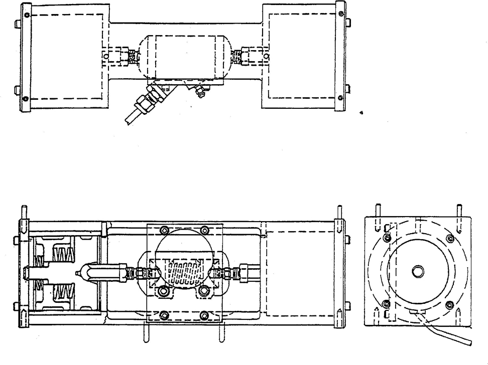
FIGURE 1—STROKING FIXTURE APPARATUS
13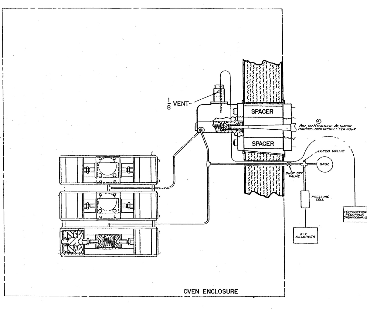
FIGURE 2—STROKING TEST APPARATUS
14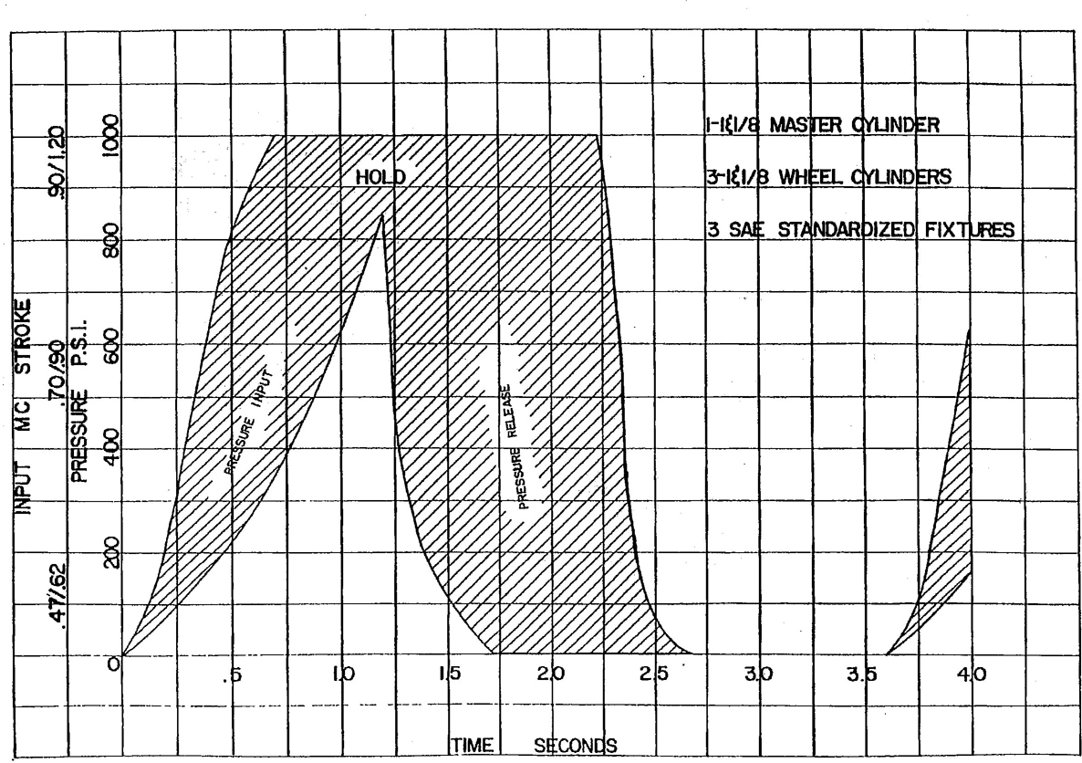
FIGURE 3—MASTER CYLINDER STROKE
155.13.2 PREPARATION OF TEST APPARATUS
5.13.2.1 Wheel Cylinder Assemblies—Use new wheel cylinder assemblies SAE RM-14b or equivalent having diameters as specified in 5.13.1.2. Pistons (SAE RM-12 or equivalent) shall be made from unanodized SAE AA 2024 aluminum alloy. Disassemble cylinders and discard rubber cups. Clean all metal parts with isopropanol or ethanol and dry with clean compressed air. Inspect the working surfaces of all metal parts for scoring, galling, or pitting and cylinder bore roughness, and discard all defective parts. Remove any stains on cylinder walls with crocus cloth and isopropanol or ethanol. If stains cannot be removed, discard the cylinder. Measure the internal diameter of each cylinder at locations approximately 19mm (0.75 in) from each end of the cylinder bore, taking measurements in line with the hydraulic intel opening and at right angles to the centerline. Discard the cylinder if any of these four readings exceeds maximum or minimum limits of 28.66 to 28.60mm (1.1285 to 1.126 in). Measure the outside diameter of each piston at two points approximately 90 degrees apart. Discard any piston if either reading exceeds maximum or minimum limits of 28.55 to 28.52mm (1.124 to 1.123 in). Select parts to insure that the clearance between each piston and mating cylinder is within 0.08 to 0.13mm (0.003 to 0.005 in). Use new standard SAE RM-3a SBR cups as specified in Figure 4 and Appendix C that are free of lint and dirt. Discard any cups showing imperfections such as cuts, tooling marks, molding flaws, or blisters. Measure the lip and base diameters of all test cups with an optical comparator or a micrometer to the nearest 0.025mm (0.001 in) along the centerline of SAE and rubber type identifications and at right angles to this centerline. Determine base diameter measurements within 0.8mm (0.032 in) of the bottom edge and parallel to the base of the cup. Discard any cups if the two measured lips or base diameters differ by more than 0.08mm (0.003 in). Average the lip and base diameters of each cup. Determine the hardness of all cups by the procedure specified in 5.6. Clean rubber parts with isopropanol or ethanol and a lint-free cloth. Dry with clean compressed air. Dip the rubber and metal parts of the wheel cylinders, except housings, in the fluid to be tested and install them in accordance with manufacturer's instructions. Rubber boots may be retained on the cylinders if a small section is removed on the bottom to observe leakage. Manually stroke the cylinders to insure that they operate easily. Install cylinders in the simulated brake system.
5.13.2.2. Master Cylinder Assembly—Use a new SAE RM-15b master cylinder or equivalent having an SAE RM-13 aluminum alloy piston or equivalent and new standard SAE RM-4a and RM-5a SBR cups as specified in Figures 5 and 6 and in Appendix C. Inspect and clean all parts as specified in 5.13.2.1. Measure each end of the master cylinder piston at two points approximately 90 degrees apart. Discard the piston if any of these readings exceed maximum or minimum limits of 28.55 to 28.52mm (1.124 to 1.123 in). Dip the secondary cup in the test brake fluid, assemble on the piston, and maintain in the assembly in a vertical position at 23 °C ± 5 °C (73.4 °F ± 9 °C) for atleast 2h. Determine the lip and base diameter of the secondary cup as installed on the piston and the primary cup at locations shown in Figure 5. Inspect the relief and supply ports of the master cylinder and discard the cylinder if these ports have burrs or wire edges. Measure the internal diameter of the cylinder at two locations: approximately midway between the relief and supply ports and approximately 19mm (0.75 in) beyond the relief port toward the bottom or discharge end of the bore, taking measurements at each location on the vertical and horizontal centerlines of the bore. Discard the cylinder if any reading exceeds maximum or minimum limits of 28.65 to 28.58mm (1.128 to 1.125 in). Dip the rubber and metal parts of the master cylinder, except the housing, in the fluid to be tested and install them in accordance with manufacturer's instructions. Discard boot and push rod assembly. Manually stroke the master cylinder to insure that it operates easily. Install the master cylinder in the simulated brake system.
5.13.2.3 Use double-wall steel tubing (SAE RM-57 or -58) or equivalent meeting SAE J527. Tubing from one outlet of master cylinder to the pair of wheel cylinders to the single wheel cylinder shall alternately be replaced with new tubing for each test (minimum length 915mm [3 ft]). Uniformity in tubing size is desirable between master cylinder and wheel cylinder, 6.3mm (1/4 in) tubing is more adaptable with available tube connectors. The standard SAE RM-15b master cylinder has two outlets for tubing, both of which should be used.
16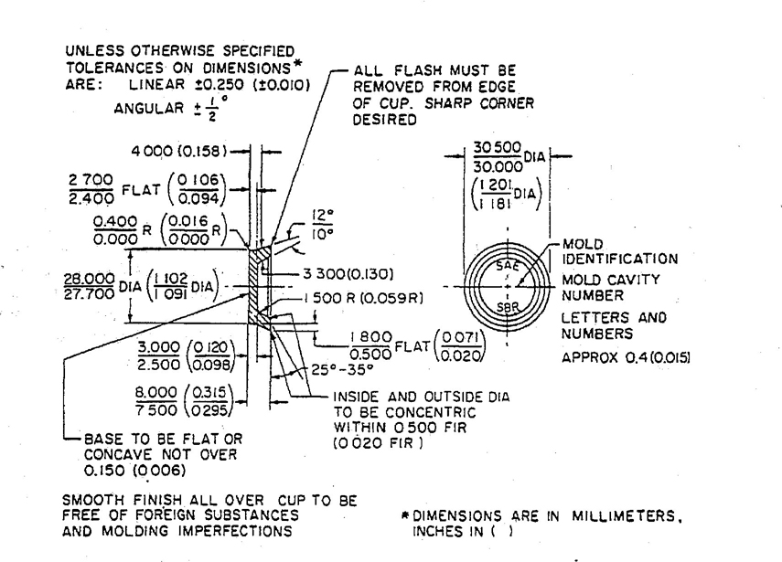
FIGURE 4—SAE TEST CUP WHEEL CYLINDER (RM-3a)
17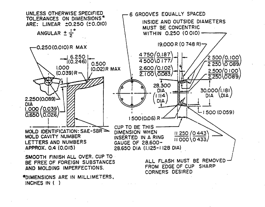
FIGURE 5—SAE TEST CUP-PRIMARY MASTER CYLINDER (RM-4a)
18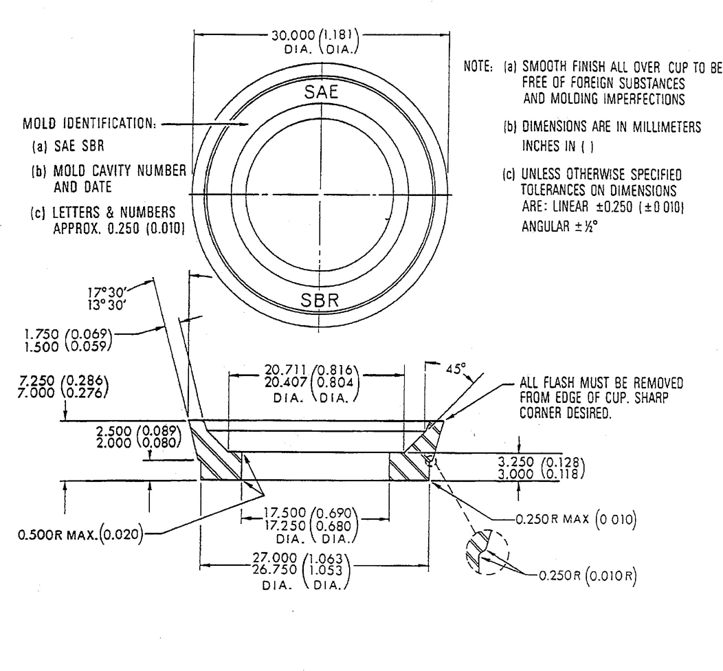
FIGURE 6—SAE TEST CUP-SECONDARY MASTER CYLINDER (RM-5a)
195.13.2.4 Assembly and Adjustment of Test Apparatus—Install wheel and master cylinders. Fill the system with test fluid, bleeding all wheel cylinders and the pressure equipment and gauges to remove entrapped air from the system.
Operate the actuator manually to apply a pressure of more than the required operating pressure and inspect the system for leaks. Adjust the actuator to obtain a pressure of 70 kg/cm2 ± 3.5 kg/cm2 (1000 ibf/in2 ± 50 lbf/in2). Figure 3 illustrates the pressure build-up versus the master cylinder piston movement with the stroking fixtures apparatus illustrated in Figures 1 and 2. The pressure is relatively low during the first part of the stroke and then builds up to 70 kg/cm2 ± 3.5 kg/cm2 (1000 lbf/in2 ± 50 lbf/in2) at the end of the stroke of approximately 25mm (1 in). The pressure build-up rate versus cylinder stroke and time shall correspond to Figure 3. The wheel cylinder piston travel is approximately 4.8mm ± 0.25mm (0.19 in ± 0.01 in) when a pressure of 70 kg/cm2 ± 3.5 kg/cm2 (1000 lbf/in2 ± 50 lbf/in2) is reached. Adjust the stroking rate to 1000 strokes/h ± 100 strokes. Record the fluid level in the master cylinder standpipe at 23 °C ± 5 °C (73.4 °F ± 9 °F) with the master cylinder piston in the fully returned position.
5.13.3 TEST PROCEDURE—Run a pressure versus stroke curve utilizing the pressure recorder at room temperature before stroking, after the fluid is at the test temperature, before shutdown at the test temperature, and at room temperature after stroking. Operate the system of 16 000 cycles ± 1000 cycles at 23 °C ± 5 °C (73.4 °F ± 9 °F). Repair any leaks and add fluid to the master cylinder standpipe to bring the fluid level to the level originally recorded at room temperature with the piston fully returned.
Start test again and raise the temperature of the fluid in the master cylinder within 6h ± 2h to 120 °C ± 5 °C (248 °F ± 9 °F). During test, observe operation of the master cylinder for complete piston return and wheel cylinders for proper operation. Observe fluid level in relation to the room temperature level at random intervals. Continue the test to 85 000 total recorded strokes which shall include the number of strokes during operation at 23 °C ± 5 °C (73.4 °F ± 9 °F), the number of strokes required to bring the system to the operating temperature of 120 °C ± 5 °C(248 °F ± 9 °F), plus the number of strokes at this operating temperature. Stop the test, and with the master cylinder piston in the fully returned position to relieve retained pressure in the system, allow the equipment to cool to room temperature.
Record the amount of fluid required to replenish any lose of fluid to the 23 °C ± 5 °C (73.4 °F ± 9 °F) level originally recorded. Stroke the assembly an additional 100 strokes at 23 °C ± 5 °C (73.4 °F ± 9 °F) and 70 kg/cm2 ± 3.5 kg/cm2 (1000 lbf/in2), examine wheel cylinders for leakage, and add and record volume of fluid required to bring the fluid level to the 23 °C ± 5 °C (73.4 °F ± 9 °F) original level.
Within 16h, remove the master and wheel cylinders from the system, retaining the fluid in the cylinders by immediately capping or plugging the ports. Disassemble the cylinders, collecting the fluid from the master cylinder and wheel cylinders in a glass jar. Record any sludge, jell, or abrasive grit present in the test fluid. When collecting the stroked fluid, all the residue which has deposited on the rubber and metal internal parts should be removed by rinsing and agitating such parts in the stroked fluid and using a soft brush to assure that all loose adhering sediment is collected.
Clean rubber cups in isopropanol or ethanol and dry with clean, compressed air. Inspect cups for tackiness, scoring, scuffing, blistering, cracking, chipping (heel abrasions), and change in shape from original appearance. Within 1h after assembly, measure the lip and base diameter of each cylinder cup by the procedure specified in 5.13.2.1 with the exception that the lip or base diameters of cups may differ by more than 0.08mm (0.003 in). Determine the hardness of each cup by the procedure specified in 5.6.
20Within 1h after draining cylinders, agitate fluid in glass jar to suspend and uniformly disperse sediment and transfer a 100mL portion of this fluid to an ASTM cone-shaped centrifuge tube and determine percent sediment as described in 5.2 of ASTM D 91. Inspect cylinder parts, recording any gum deposits. Rub any deposits adhering to cylinder walls with a cloth wetted with isopropanol or ethanol to determine abrasiveness and removability. Clean cylinder parts in isopropanol or ethonol to determine abrasiveness and removability. Measure and record diameters of positions and cylinders by the procedures specified in 5.13.2.1 and 5.13.2.2.
Calculate lip diameter interference set by the following formula:
where
D1 = Original lip diameter
D2 = Final lip diameter
D3 = Original cylinder bore diameter
Repeat the test if mechanical failure occurs that may affect the evaluation of the test fluid.
6. Notes
6.1 Marginal Indicia—The (R) is for the convenience of the user in locating areas where technical revisions have been made to the previous issue of the report. If the symbol is next to the report title, it indicates a complete revision of the report.
PERPARED BY THE SAE MOTOR VEHICLE BRAKE FLUIDS STANDARDS COMMITTEE
21| Corrosion Test Strip | Material Specification | General Material Data | Dimensions | Surface Requirements |
|---|---|---|---|---|
| Tinned iron RM-6a | ASTM A 624, Federal Specification QQ-T-425A | SR tin plate electrolytic, bright; No. 25, type MR Temper 3, base weight 85 lb Ferrostand and DOS oil |
Approx. 8 cm long; 1.3 cm wide Thickness; As purchased Surface area: 25cm2 ± 5 cm2 |
As sheared. Clean and uniform tinning. |
| Steel RM-7 | SAE 1018 | Low carbon sheet Cold rolled Hardness:40 to 72 RB |
Approx. 8 cm long; 1.3 cm wide Thickness: Approx. 0.2 cm Surface area: 25 cm2 ± 5 cm2 |
Edges machined to remove shearing marks. Clean uniform surfaces. |
| Aluminum RM-8 | SAE AA2024 | Wrought aluminum alloy Temper T3 Hardness: 75 RB typical |
Approx. 8 cm long; 1.3 cm wide Thickness: Approx. 0.2 cm Surface area: 25 cm2 ± 5 cm2 |
Edges machined to remove shearing marks. Clean uniform surfaces. |
| Cast iron RM-9 | SAE G3000 | Soft automotive cast iron. Must be free from shrinkage cavities, porosity, or any other defects detrimental to specification use of the material. Hardness: 86 to 98 RB |
Approx. 8 cm long; 1.3 cm wide Thickness: Approx 0.2 cm Surface area: 25 cm2 ± 5 cm2 |
Surface grind 4 sides to dimension using a well-dressed No. 80 Alundum wheel. Clean uniform surfaces. |
| Brass RM-10 | SAE CA260 | Wrought alloy—yellow brass Rolled sheet or strip: half hard temper Hardness: 57 to 74 RB |
Approx. 8 cm long; 1.3 cm wide Thickness: Approx. 0.2 cm Surface area: 25 cm2 ± 5 cm2 |
Edges machined to remove shearing marks. Clean uniform surfaces. |
| Copper RM-11 | SAE CA114 | Cold rolled copper sheet or strip Half-hard temper Hardness: 35 to 56 RB |
Approx. 8 cm long; 1.3 cm wide Thickness: Approx. 0.2 cm Surface area: 25 cm2 ± 5 cm2 |
Edges machined to remove shearing marks. Clean uniform surfaces. |
| Zinc ISO-2 | 2N AL4 CU1 ISO/R 301 | Die casting alloy strips Hardness: 85 to 105 HB |
Approx. 8 cm long; 1.3 cm wide Thickness: Approx. 0.2 cm Surface area: 25 cm2 ± 5 cm2 |
Edges machines to remove shearing marks. Clean uniform surfaces. |
| NOTES—Drill hole between 4 and 5mm in a diameter and approximately 6mm from one end of each strip. Holes to be clean and free from burrs. Hardness ranges are commercially for the designated metals. Hardness is not specified for the tinned iron because it is not considered a practical requirement. | ||||
7 Obtainable from the Society of Automotive Engineers, Inc., 400 Commonwealth Drive, Warrendale, PA 15096-0001.
22This fluid is a blend of six proprietary polyglycol brake fluids of fixed composition, in equal parts by volume. The six fluids selected comprise five factory-fill and one aftermarket fluid, as follows:
8 Obtainable from the Society of Automotive Engineers, Inc., 400 Commonwealth Drive, Warrendale, PA 15096-0001.
23C.1 Formulation of Rubber Compound—(See Table C1)
| Ingredient | Parts by Weight |
|---|---|
| SBR type 15031 | 100 |
| Oil furnace black (NBS 378) | 40 |
| Zinc oxide (NBS 370) | 5 |
| Sulfur (NBS 371) | 0.25 |
| Stearic acid (NBS 372) | 1 |
| n-tertiary butyl-2-benzothiazole sulfenamide (NBS 384) | 1 |
| Symmetrical-dibetanophthyl-p-phenylene diamine | 1.5 |
| Dicumyl peroxide (40% on precipitated CaCo3)2 | 4.5 |
| Total | 153.25 |
| NOTE—The ingredients labeled (NBS) must have properties identical with those supplied by the National Institute of Standards and Technology. 1 Philprene 1503 has been found suitable. 2 Use only within 90d of manufacture and store at temperature below 27 °C (80 °F) |
|
C.2 Procedure for Mixing Rubber Compound—The rubber compound shall be mixed in accordance with the procedure given in ASTM D 3185 for Formula 2B.
C.3 Properties of Rubber Compound—Vulcanizates cured for 12 min at 180 °C (356 °F) by the procedure described in ASTM D 3182 shall meet the requirements in Table C2:
24| Property | Requirement | ASTM Method |
|---|---|---|
| Hardness | 63 ± 3 | D 1415 or D 2240 |
| Tensile strength | 17.5 MPa (2500 lbf/in2, min) | D 412 |
| Ultimate elongation | 350%, min | D 412 |
| Tensile strength after 70h at 125 °C (257 °F) | 30% decrease, max | D 865 |
| Ultimate elongation after 70h at 125 °C (257 °F) | 50% decrease, max | D 865 |
| Hardness after 70h at 125 °C (257 °F) | 0 to 10 increase | D 865 |
| Compression set after 22h at 125 °C (257 °F) | 15 to 20% | D 395 (Method B) |
| Brittleness temperature | −40 °C (−40 °F), max | D 746 |
C.4 Brake Cups Prepared From Rubber Compound—Brake cups9 shall be prepared from the rubber compound by vulcanization under the conditions required to obtain the properties given in Section C.3. The dimensions of the cups shall be suitable for the brake cylinders used to determine stroking test procedure in 5.13. Cups may be used for testing brake fluids within 36 months from date of manufacture when stored in the dark at ambient temperatures not exceeding 38 °C (100 °F) and adequately protected from atmospheric and other contaminants. After removal of cups from storage, they shall be conditioned base down on a flat surface for at least 12h at room temperature in order to allow cups to reach their true configuration before measurement.
9 Obtainable from the Society of Automotive Engineers, Inc., 400 Commonwealth Drive, Warrendale, PA 15096-0001.
25D.1 Formulation of Rubber Compound—(See Table D1)
| Ingredient | Parts by Weight |
|---|---|
| EPDM type (Nordel 1320)1 | 100 |
| Zinc oxide (NBS 370) | 5 |
| Oil furnace black (NBS 378) | 43 |
| Polymerized 1,2-dihydro-2,2,4-trimethylquinoline | 2 |
| Dicumyl peroxide (40% on precipitated CaCO3)2 | 10 |
| Total | 160 |
| NOTE—The ingredients labeled (NBS) must have properties identical with those supplied by the National Institute of Standards and Technology. 1 E.I. DuPont Nordel EPDM 1320. 2 Use only within 90d of manufacture and store at a temperature below 27 °C (80 °F). |
|
D.2 Procedure for Mixing Rubber Compound—The rubber compound shall be mixed in accordance with the procedures given in ASTM D 3182.
D.3 Properties of Rubber Compound—Vulcanizates cured for 25 min at 175 °C (347 °F) by the procedure described in ASTM D 3182 shall meet the requirements as in Table D2:
26| Property | Requirement | ASTM Method |
|---|---|---|
| Hardness, IRHD | 70 ± 3 | D 1415 |
| Tensile strength, min | 13.8 MPa (2000 lbf/in2) | D 412 |
| Ultimate elongation, min | 225% | D 412 |
| Tensile strength, decrease after 22h at 175 °C (347 °F), max | 15% | D 865 |
| Ultimate elongation, decrease after 22h at 175 °C (347 °F), max | 30% | D 865 |
| Hardness, increase after 22h at 175 °C (347 °F) | 0 to 10 | D 865 |
| Compression set after 22h at 175 °C (347 °F) | 20%max | D 395 (Method B) |
| Brittleness temperature, max | −65 °F | D 746 |
D.4 Slabstock Prepared From Rubber Compound—Test slabs approximately 150mm × 150mm × 1.9mm (6 in × 6 in × 0.075 in) shall be prepared from the rubber compound by vulcanization under the conditions stated in Section D.3. These slabs may be used in testing brake fluids within 36 months from their date of manufacture, when stored in the dark at ambient temperatures not exceeding 38 °C (100 °F) and adequately protected from atmospheric or other contaminants.
27When stored at other than 23 °C ± 5 °C (73.4 °F ± 9 °F), the material shall be allowed to stabilize at laboratory temperature prior to measurements.
| Property | Requirement | Method |
|---|---|---|
| Assay | 94 area %, min Further, neither the material preceding nor that following TEGME through the column shall exceed 4 area % |
Gas Chromatographic (GC) analysis (see blow) |
| Water content | 0.3% by weight, max | ASTM D 1364 |
| Acidity | 0.02% by weight, max, as acetic acid | ASTM D1613 |
| Suspended matter | Substantially free | — |
| Appearance | Clear liquid; 100 APHA units, max | ASTM D 1209 |
| ERBP | 240 °C (464 °F), min | Paragraph 5.1 of SAE Standard J1703 |
E.1 Gas Chromatographic Analysis—Analyze a representative sample using a Bendix Model 2200 dual column, programmed temperature gas chromatograph, or equivalent instrument, with a thermal conductivity detector and two 10 ft × 1/8 in Type 304 stainless steel columns packed with 10% CARBOWAX 20M-terephthalic acid on Chromosorb T, 40 to 60 mesh, as follows:
E.1.1 Column Preparation—Use precleaned tubing or obtain two 10 ft lengths of 1/8 in 304 stainless steel tubing (0.02 in wall thickness) and clean as follows:
E.1.1.1 Weigh 5g of CARBOWAX 20M-terephthalic acid into a 400mL beaker. Add 200mL of methylene chloride and stir with a magnetic stirrer until dissolved. Approximately 30 min will be required.
E.1.1.2 Weigh 45g of Chromosorb T, 40 to 60 mesh into a tared beaker and transfer to a 500mL rotary evaporating flask.
E.1.1.3 Add the CARBOWAX 20M-TPA solution to the flask and mix by gently swirling. If necessary, add additional methylene chloride to form a set slurry.
E.1.1.4 Allow the slurry to stand for 10 min.
10 Stabilized by addition of 1/4% by weight of 4.4′ isopropylidene diphenol.
11 Obtainable from the Society of Automotive Engineers, Inc., 400 Commonwealth Drive, Warrendale, PA 15096-0001.
28E.1.1.5 Attach the flask to a rotary evaporator and apply vacuum slowly while degassing. Set the pressure at approximately 100mm Hg. Use dry ice-acetone traps to protect the vacuum source.
E.1.1.6 Rotate the flask at 10 rpm.
E.1.1.7 Protect the contents of the flask from extreme cold or heat by means of a hot air gun (hair dryer at 50 to 60 °C).
E.1.1.8 When all of the solvent has been removed, stop the evaporator and allow the contents of the flask to return to room temperature.
NOTE—If a rotary evaporator is not available, satisfactory packing may be prepared using the evaporating dish technique.
E.1.1.9 Transfer the dried packing to a bottle having a volume about twice the volume of the packing.
E.1.1.10 Add 0.5% by weight of powdered graphite and mix thoroughly until the mixture flows freely.
E.1.1.11 Sieve the mixture using a combination of 30-and 60-mesh screens. Retain the portion that passes through the 30-mesh and is retained on the 60-mesh screen.
E.1.1.12 Using a funnel, pack the columns with approximately 7g of packing by gently tapping the side of the column with a suitable metal rod. Do not add large quantities of packing to the funnel at one time.
E.1.1.13 Condition the columns by programming from ambient temperature to 200 °C at 2 °C/min and hold at 200 °C for at least 4h. Repeatedly inject a sample until a good baseline is obtained.
E.1.2 Operating Parameters
E.1.3 Procedure—Inject the sample into the chromatograph and obtain the chromatogram using the parameters outlined in E.1.2.
E.1.3.1 Measure the areas of all component peaks using an electronic integrator or a planimeter.
E.1.3.2 Calculate and report the area percent of TEGME. The TEGME elutes at about 15 min.
29E.1.3.3 CALCULATION
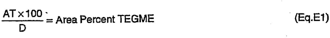
where:
30A = Peak area for TEGME
D = Total area, sum of all areas corrected for attenuation
T = Attenuation for component peak
Rationale—Ethanol was added as an option to isopropanol, pH was changed from 7 to 7.0, the tin foil assay was changed from 0.20% lead, max to 0.5% lead, max and the drum and shoe reference was removed from the stroking test procedure. The RM-66-03 compatibility fluid has been replaced by a more modern RM-66-04 compatibility fluid.
Relationship of SAE Standard to ISO Standard—Similar to ISO 4925.
Application—This SAE Standard covers motor vehicle brake fluids of the nonpetroleum type for use in the braking system of any motor vehicle such as a passenger car, truck, bus, or trailer. These fluids are not intended for use under arctic conditions. These fluids are designed for use in braking systems fitted with rubber cups and seals made from natural rubber (NR), styrene-butadiene rubber (SBR), or a terpolymer of ethylene, propylene, and a diene (EPDM).
Reference Section
SAE J527—Brazed Double Wall Low Carbon Steel Tubing
ASTM D 91—Test Method for Precipitation Number of Lubricating Oils
ASTM D 344—Method of Test for Relative Dry Hiding Power of Paints
ASTM D 445—Test Method for Kinematic Viscosity of Transparent and Opaque Liquids (and the Calculation of Dynamic Viscosity)
ASTM D 664—Test Method for Neutralization Number of Potentiometric Titration
ASTM D 1120—Method of Test for Boiling Point of Engine Antifreezes
ASTM D 1415—Method of Test for International Hardness of Vulcanized Natural Rubber and Synthetic Rubbers
ASTM D 2240—Method of Test for Indentation Hardness of Rubber and Plastics by Means of a Durometer
ASTM D 3182—Recommended Practice for Rubber-Materials, Equipment, and Procedures for Mixing Standard Compounds and Preparing Standard Vulcanized Sheets
ASTM D 3185—Methods for Rubber-Evaluation of SBR (Styrene-Butadiene Rubber) including Mixtures with Oil
ASTM E 1—Specification for ASTM Thermometers
ASTM E 260-73—Standard Recommended Practice for General Gas Chromatography Procedure
Developed by the SAE Motor Vehicle Brake Fluids Standards Committee
31