
In order to promote public education and public safety, equal justice for all, a better informed citizenry, the rule of law, world trade and world peace, this legal document is hereby made available on a noncommercial basis, as it is the right of all humans to know and speak the laws that govern them.
A Product of the Cooperative Engineering Program
SAE J1383 APR85
SAE Recommended Practice Issued April 1985
S. A. E.
LIBRARY
An American National Standard
ii
No part of this publication may be reproduced in any form, in an electronic retrieval system or otherwise, without the prior written permission of the publisher.
Copyright 1986 Society of Automotive Engineers, Inc.
iiiPERFORMANCE REQUIREMENTS FOR MOTOR
VECHICLE HEADLAMPS—SAE J1383 APR85
SAE Recommended Practice
Report of the Lighting Committee, approved April 1985. Rationale available.
1. Scope—This recommended practice is intended as a guide toward standard practice and is subject to change to keep pace with experience and technical advances. This recommended practice establishes performance requirements, material requirements, design requirements, and design guidelines for 12 V headlamps.
2. Definitions
2.1 Headlamp—A lighting device providing an upper and/or a lower beam used for providing illumination forward of the vehicle.
2.1.1 SEALED BEAM HEADLAMP—An integral and indivisible optical assembly including the light source with “sealed beam” molded in the lens.
2.1.2 REPLACEABLE BULB HEADLAMP—A divisible optical assembly in which the light source and other parts may be replaced.
2.2 Upper Beam—A beam intended primarily for distance illumination and for use when not meeting or closely following other vehicles.
2.3 Lower Beam—A beam intended to illuminate the road and its environs ahead of the vehicle when meeting or closely following another vehicle.
2.4 Mechanically Aimable Headlamp—A headlamp having three pads on the lens, forming an aiming plane used for laboratory photometric testing and for adjusting and inspecting the aim of the headlamp when installed on the vehicle.
2.5 Aiming Plane—A plane defined by the surface of the three aiming pads on the lens.
2.6 Headlamp Mechanical Axis—The line formed by the intersection of a horizontal and a vertical plane through the light source parallel to the longitudinal axis of the vehicle. If the mechanical axis of the headlamp is not at the geometric center of the lens, then the location will be indicated by the manufacturer on the headlamp.
2.7 H-V Axis—A line from the center of the principal filament to the intersection of the horizontal (H) and vertical (V) lines on the screen (see Fig. 1).
2.8 Light Source for a Headlamp
2.8.1 SEALED BEAM HEADLAMP—The filament or other source of radiant energy and the integral and indivisible optical assembly providing the light.
2.8.2 REPLACEABLE BULB HEADLAMP—The filament or other source of radiant energy and its containing envelope providing the light.
2.9 Seasoning—Process of energizing the filament of a headlamp at design voltage for a period of time equal to 1% of design life. Other equivalent methods are acceptable.
2.10 Design Voltage—The voltage used for design purposes.
2.11 Test Voltage—The specified voltage and tolerance to be used when conducting a test.
2.12 Rated Voltage—The nominal circuit or vehicle electrical system voltage classification. (Example: 12 V headlamp.)
2.13 Headlamp Test Fixture—Device specifically designed to support a headlamp in the test position during laboratory testing. Mounting hardware and components shall be representative of those necessary to operate the headlamp in its normal manner.
3. Lighting Identification Code—Headlamps may be identified in accordance with SAE J759 MAY83, Lighting Identification Code.
Letters indicating device functions are:
H—Sealed Beam Headlamp
HH—Sealed Beam Headlamp Housing
HR—Replaceable Bulb Headlamp
4. Tests
4.1 SAE J575, Tests for Motor Vehicle Lighting Devices and Components is a part of this report. The following tests are applicable with the modifications as indicated.
4.1.1 VIBRATION TEST
4.1.1.1 The headlamp shall be seasoned and photometered to the test points in Table 4 before and after the vibration test (see 4.1.4).
4.1.1.2 The test fixture with the test headlamp installed shall have a resonant frequency greater than 2000 Hz.
4.1.1.3 Frequency—Varied from 50-1000 Hz and returned to 50 Hz at a linear sweep period of 2 min/complete sweep cycle.
4.1.1.4 Filament—The filarnent shall be cold (not energized) for this test.
4.1.1.5 The continuity of the filament(s) shall be monitored throughout the test period.
4.1.1.6 Wave Form—Sinusoidal.
4.1.1.7 A standard headlamp shall be tested for 30 complete cycles at a vertical acceleration of 49 m/s2 peak measured on the table. (See Table 6.)
4.1.1.8 A heavy-duty headlamp shall be tested for 90 complete cycles at a vertical acceleration of 98 m/s2 peak measured on the table. (See Table 6.)
4.1.2 DUST TEST—The headlamp shall be seasoned and photometered to the test points in Table 4 before and after the dust test.
4.1.3 CORROSION TEST
4.1.3.1 The headlamp shall be seasoned and photometered to the test points in Table 4 before and after the corrosion test.
4.1.3.2 The headlamp shall be rigidly mounted in a test fixture, on its seating plane, in its design operating condition and design mounting position.
1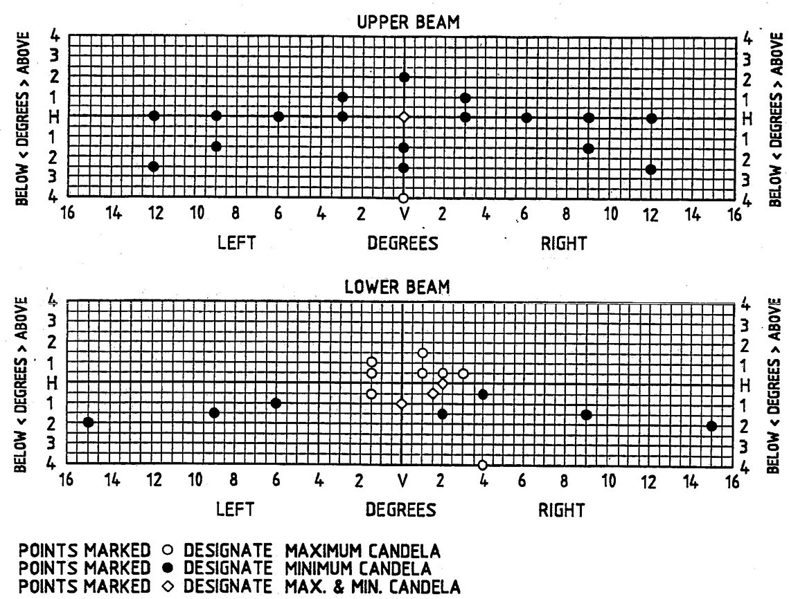
FIG. 1
24.1.3.3 The test period shall be 240h consisting of 10 cycles of 23h exposure followed by 1h drying.
4.1.4 PHOTOMETRY
4.1.4.1 The headlamp shall be seasoned.
4.1.4.2 Photometric tests shall be made with the photometer sensor at a distance of at least 18.3m from the headlamp.
4.1.4.3 The headlamp shall be aimed mechanically with the aiming plane at the design angle(s) to the photometer axis and the mechanical axis of the headlamp on the photometer axis.
4.1.4.4 Test Voltage—The voltage for the photometric tests shall be 12.8 V ± 20 mV, DC as measured at the terminals of the lamp.
4.2 Color Test—SAE J578, Color Specification for Electric Signal Lighting Devices is a part of this report.
4.3 Plastic Materials—SAE J576, Plastic Materials for Use in Optical Parts Such as Lenses and Reflectors of Motor Vehicle Lighting Devices is a part of this report except paragraph 4.2.1, Luminous Transmittance.
4.4 Beam Pattern Location Test
4.4.1 Headlamps designed to be aimed on the upper beam, with (numeral) “1” as the first character of the headlamp identification code, shall be seasoned and photometered to find the location of maximum intensity. (See paragraph 4.1.4).
4.4.2 Headlamps designed to be aimed on the lower beam, with (numeral) “2” as the first character of the headlamp identification code, shall be seasoned and photometered (see paragraph 4.1.4) at the test points H-2R and ID-V. (See paragraph 4.1.4)
4.5 Photometric Performance Test
4.5.1 Test samples shall be new, unused headlamps manufactured from production tooling and assembled by production processes.
4.5.2 The headlamps shall be seasoned and photometered at the appropriate test points as listed in Table 3. (See 4.1.4)
4.6 Filament Life Test
4.6.1 Tungsten filaments burn out at a normal distribution level. Testing to determine the rated average lab life shall be done on lot sizes established by the manufacturer. The manufacturer shall obtain and be able to supply this data.
4.6.2 TEST VOLTAGE—The headlamp shall be operated at 14 V ± 0.1 V.
4.6.3 The headlamp shall be mounted in the design burning position for this test.
4.6.4 The light source shall be tested in its design enclosure or a standard enclosure. The standard enclosure for the purpose of this filament life test is an enclosure as shown in Fig. 10. Other correlated test methods are acceptable.
4.6.5 The filament shall be turned off 15 min for each 24h of testing. The off time is not part of the test time of the filament being tested. Other correlated test methods are acceptable.
4.7 Wattage Test—The wattage of each filament of a light source shall be determined at 12.8 V ± 20 mV DC after seasoning.
4.8 Maintenance of Luminous Intensity Test
4.8.1 The mean spherical candlepower value of tungsten filaments or the maximum beam candlepower value of a headlamp has a normal distribution level. Testing to determine the minimum average mean spherical candlepower value or the minimum average maximum beam candlepower value, shall be done on lot sizes established by the manufacturer. The value, shall be done on lot sizes established by the manufacturer. The manufacturer shall obtain and be able to supply this data.
4.8.2 The light source shall be tested in its design burning position, in its design enclosure, or a standard enclosure (see 4.6.4).
4.8.3 Test samples shall be seasoned.
4.8.4 The test voltage for burning the headlamp to 70% of the design life shall be 14 ± 0.1 VDC. The test voltage for photometric measurements shall be 12.8 V ± 20 mV DC.
4.8.5 Double filament light sources shall be tested by cycle burning the upper beam filament 12 min and the lower beam filament 48 min for each hour of testing. Other correlated test methods are acceptable.
4.8.6 The mean spherical candlepower of a single filament light source, or the maximum beam candlepower value of a single filament headlamp shall be measured after seasoning and after burning for 70% of the design life.
4.8.7 The mean spherical candlepower of each filament of a double filament light source, or the maximum beam candlepower of each beam of a double filament headlamp shall be measured after seasoning and after the lower beam filament on time equals 70% of the design life when tested according to paragraph 4.8.5.
4.9 Out-of-Focus Test
4.9.1 This test shall be conducted on headlamps with replaceable light sources.
4.9.2 The headlamp shall be mounted in the goniometer with the mechanical axis concident with the photometer axis.
4.9.3 The test voltage for the headlamp shall be 12.8 V ± 20 mV DC.
4.9.4 The headlamp shall be photometered at the appropriate test points as listed in Table 3.
4.9.5 Intensity measurements shall be made at six out-of-focus positions with the filament located at ⅔ of the tolerance value specified for the filament tolerance specifications listed in Table 7.
4.10 Impact Test
4.10.1 The headlamp shall be rigidly mounted in a test fixture on the seating plane with the lens facing up.
4.10.2 The seating plane of the test fixture shall consist of 13 mm thick oak wood. The test fixture shall rest on an oak wood base.
4.10.3 One impact shall be delivered to the headlamp lens along the mechanical axis using a 23 mm diameter steel sphere (approximately 50 g) dropped freely, without side forces, from a distance of 40 cm above the lens.
4.11 Lens Inward Force Test
4.11.1 The headlamp shall be rigidly mounted in a test fixture on its seating plane. A 25 mm (1 in) spherical ball shall apply a steady force of 90 N (20 lb) along the mechanical axis of the headlamp for 10 min.
4.11.2 This test is to be conducted in an ambient temperature of 23 ± 4°C (73 ± 7°F). This lamp is not to be energized (lighted) during this test.
4.11.3 For a suggested test fixture, see Fig. 2.
4.12 Chemical Resistance Test
4.12.1 The test shall be conducted with the headlamps and the test fluids at an ambient temperature of 23 ± 4°C.
4.12.2 The test headlamps shall be seasoned and photometered to the test points in Table 4 before and after the chemical resistance test (see paragraph 4.1.4).
4.12.3 A separate headlamp shall be used for each of the test fluids.
4.12.4 The test fluids are:
Motor oil—Designated by API with SF quality.
Tar remover (petroleum base).
Power steering fluid.
Windshield washer fluid (50% concentration by volume of methanol/detergent base, 0.16% ethanolamine).
Antifreeze (50% concentration by volume of ethylene glycol in water).
Unleaded gasoline.
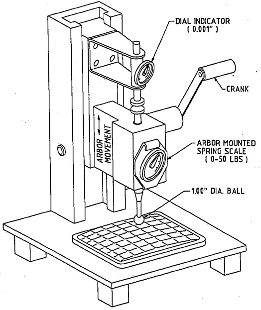
FIG. 2—INWARD FORCE TESTER
34.12.5 An unfixtured headlamp in its design operating condition and design mounting position shall have the exterior surface of the headlamp coated with the test fluid by hand wiping with a thoroughly saturated soft cotton cloth. The test fluid shall be applied in sufficient quantity to cause dripping from the bottom of the headlamp.
4.12.6 After applying the test fluid, the test headlamp shall be rigidly mounted on its seating plane in the design mounting position and set aside for a period of 15 days.
4.12.7 At the end of the 15 day time period, the headlamp shall be removed from the test fixture and wiped clean with a soft, dry, cotton cloth.
4.13 Abrasion Test of Plastic Headlamp Lens Material
4.13.1 A 100 ×165 mm flat test specimen shall be measured for luminous transmittance before and after wiping clean after the abrasion test.
4.13.2 The test specimen shall be mounted in the abrasion test machine as indicated in Fig. 3.
4.13.3 The size of the abrading pad shall be 25 ×100 mm constructed of 0000 steel wool and firmly attached to a pad support of equal size such that the “grain” of the pad is perpendicular to the direction of motion.
4.13.4 The abrading pad shall be loaded such that an average pad pressure of 14 ± 1 kPa exists normal to the surface of the test specimen.
4.13.5 The density of the abrading pad shall be such that when the abrading pad mounted to the pad support is resting unloaded on the test specimen, the pad support shall be no closer than 3.1 mm to the surface of the test specimen.
4.13.6 An abrasion cycle is one forward stroke 10 ± 2 cm and one rearward stroke of the same distance. The velocity of the abrading pad shall be 10 ± 2 cm/s.
4.13.7 The test specimen shall be subjected to 20 abrasion cycles.
4.14 Thermal Cycle Test
4.14.1 The headlamp shall be seasoned and photometered to the test points in Table 4 before and after the thermal cycle test (see paragraph 4.1.4).
4.14.2 The headlamp shall be rigidly mounted in a test fixture on its seating plane in its design operating condition and design mounting position.
4.14.3 The headlamp shall be exposed to the thermal cycle profile shown in Fig. 4.
4.14.4 Separate or single test chambers may be used to generate the temperature environment described by the thermal cycle.
4.14.5 The headlamp shall be energized at 12.8 V ± 20 mV, in its highest wattage mode commencing at point “A” of Fig. 4 and de-energized at point “B” of each cycle.
4.14.6 The test period shall be 10 cycles of 8h per cycle.
4.15 Thermal Shock Test
4.15.1 An unfixtured headlamp in its design operating condition and design mounting position shall be energized in its highest wattage mode for a test period of 45 min.
4.15.2 The test voltage for the headlamp shall be 12.8 ± 0.1 V.
4.15.3 At the end of the test period, the headlamp shall be de-energized and immediately submerged, lens first, into ice water at 0 +3 −0°C (32 +5 −0°F) for a period of 5 min.
4.16 Internal Heat Test
4.16.1 The headlamp shall be seasoned and photometered to the test points in Table 4 before and after the internal heat test (see 4.1.4).
4.16.2 The headlamp shall be rigidly mounted in a test fixture on its seating plane in its design operating condition and design mounting position.
4.16.3 A dirt mixture, soluble in water, shall be sprayed uniformly on the face of the lens and allowed to dry until the light intensity at H-V is reduced by 50% of its original value.
4.16.4 The headlamp shall be energized in its highest wattage mode and placed in a chamber at 35 ± 3°C.
4.16.5 The test cycle shall be 30 min.
4.16.6 The test voltage for the headlamp shall be 12.8 ± 0.1 V.
4.16.7 After the internal heat test, the lens face shall be wiped clean.
4.17 Humidity Test
4.17.1 The headlamp shall be seasoned and photometered to the test points in Table 4 before and after the humidity test (see paragraph 4.1.4).
4.17.2 The headlamp shall be rigidly mounted in a test fixture on its seating plane, in its design operating condition and design mounting position.
4.17.3 The headlamp shall be placed in a controlled environment of 95 ± 5% relative humidity at 38°C (100°F).
4.17.4 The headlamp shall be energized in its highest wattage mode for a test cycle of 1h “on” and 5h “off”.
4.17.5 The test voltage for the headlamp shall be ± 0.1 V.
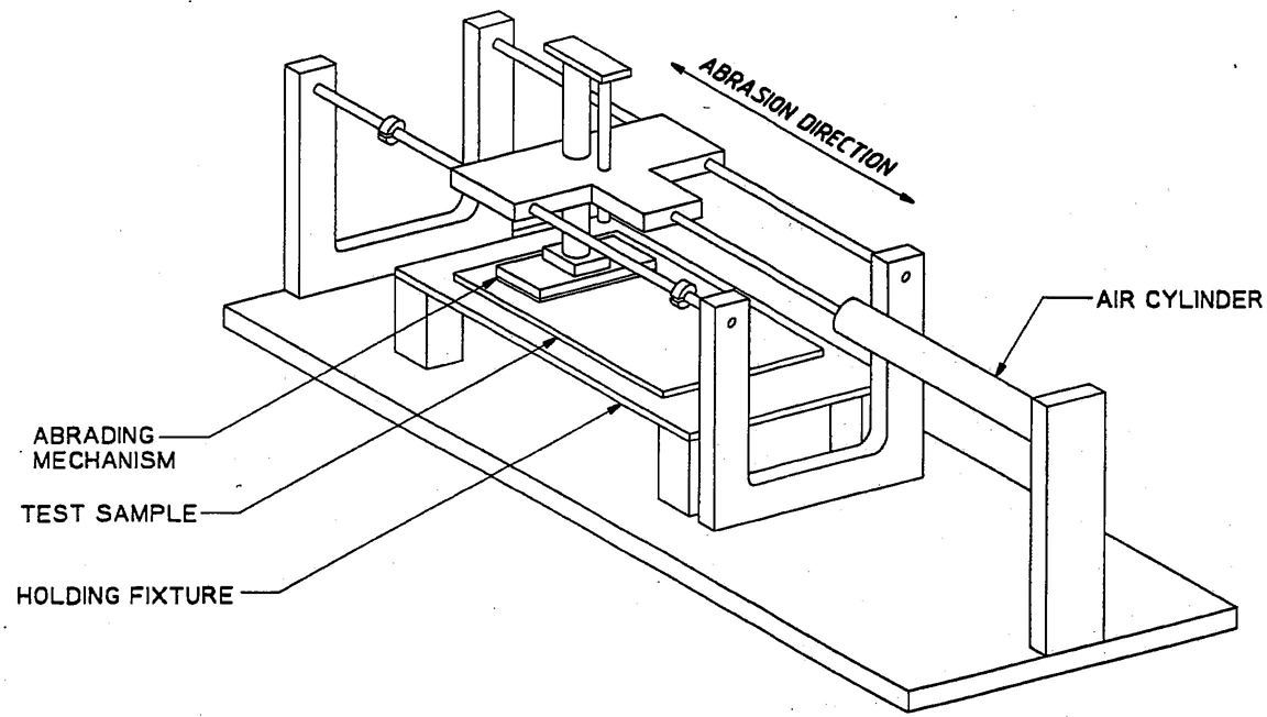
FIG. 3—ABRASION TEST MACHINE
4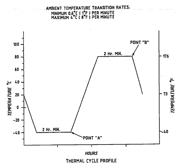
FIG. 4—THERMAL CYCLE PROFILE
4.17.6 TEST DURATION—Ten complete cycles. The test is to end in the “off” cycle mode.
4.17.7 After completion of the tenth test cycle, the headlamp is to be removed from the humidity chamber and energized at the test voltage in its lowest wattage mode for a period of 10 min.
4.18 Test Sequence—The test procedures and test requirements specified in this recommeded practice were developed emphasizing extreme conditions in the headlamp environment. Separate headlamps shall be used for each test.
5. Requirements
5.1 Performance Requirements—A headlamp, when tested in accordance with the test procedures specified in Section 4, shall meet the following requirements.
5.1.1 VIBRATION (SAE J575)—The photometric values measured after the vibration test shall not vary more than ±10% from the values measured before the test. Evidence of loose or broken parts, or intermittent electrical circuit shall constitute failure of this test.
5.1.2 DUST TEST (SAE J575)—The Photometric values measured after the dust test shall not vary by more than ±10% from the values measured before the test.
5.1.3 CORROSION (SAE J575)—The test headlamp shall show no evidence of exterior or internal corrosion or edge corrosion beyond 2 mm (0.08 in) from a sheared or cut edge. The headlamp shall show no evidence of surface deterioration, fractures, color bleeding, or deterioration of bonding materials. The photometric values measured after the corrosion test shall not vary more than ±10% from the values measured before the test.
5.1.4 COLOR—The color of a headlamp shall be white as specified in SAE J578.
5.1.5 BEAM PATTERN LOCATION
5.1.5.1 Headlamps Designed to be Aimed on the Upper Beam——The beam pattern is properly oriented to the aiming plane if the location of the maximum beam intensity point does not deviate from the H-V axis more than ±0.5 deg vertically and ±0.8 deg horizontally (rectangular box).
5.1.5.2 Headlamps Designed to be Aimed on the Lower Beam—The beam pattern is properly oriented to the aiming plane if the intensity requirements listed in Table 1 for the test points H-2R and 1D-V are met.
5.1.6 PHOTOMETRIC PERFORMANCE—The headlamp shall meet the photometric requirements shown in Table 3.
5.1.7 WATTAGE—Measured wattage shall not exceed the design wattage listed in Table 6 by more than 7.5%.
5.1.8 OUT-OF-FOCUS—The headlamp shall meet the requirements of Table 3 for each of the out-of-focus test positions.
5.1.9 MAINTENANCE OF LUMINOUS INTENSITY
5.1.9.1 The average mean spherical candlepower value of single filament light sources, or the average maximum beam candlepower value of single filament headlamp after burning for 70% of design life, shall be no less than 90% of the average value measured after seasoning.
5.1.9.2 The average mean spherical candlepower value of each filament of double filament light sources, or the average maximum beam candlepower value of each beam of dual filament headlamp when tested according to paragraphs 4.8.5 and 4.8.7 shall be no less than 90% of the average value measured after seasoning.
5.1.10 IMPACT—The headlamp shall show no evidence of broken, cracked, or chipped pieces of the headlamp, coating adhesion failure, or delamination of material, or visible loosening or breaking apart of headlamp parts.
5.1.11 LENS INWARD FORCE—Maximum deflection during load application shall not exceed 2.5 mm (0.1 in). Permanent set of the lens face after the load is removed shall not exceed 0.1 mm (0.004 in) measured 24h after load removal.
5.1.12 CHEMICAL RESISTANCE—The exposed headlamp, when compared to an unexposed headlamp, shall not show surface deterioration, delamination, fractures, deterioration of bonding materials, color bleeding, or color pickup as a result of exposure to the test fluids. The photometric values measured after the chemical resistance test shall not vary more than ±10% from the values measured before the test.
5.1.13 THERMAL CYCLE—The headlamp shall show no evidence of delamination, fractures, seal fractures, deterioration of bonding material, color bleeding, warp, or deforming. The photometric values measured after the temperature cycle test shall not vary by more than±10% from the values measured before the test.
5.1.14 THERMAL SHOCK—The headlamp shall show no evidence of fractures, delamination, or seal failure.
5.1.15 INTERNAL HEAT—The photometric values measured after the internal heat test shall not vary by more than ±10% from the values measured before the test.
5.1.16 HUMIDITY—At the end of the 10 min test period (see 4.17.7) the headlamp shall be inspected immediately and show no evidence of condensed moisture or droplets inside the headlamp.
The headlamp shall show no evidence of delamination, bonding, material deterioration, or seal failure. The photometric values measured after the humidity test shall not vary by more than ±10% from the values measured before the test.
5.2 Material Requirements
5.2.1 SAE J576, except Luminous Transmittance, paragraph 4.2.1.
5.2.2 ABRASION OF PLASTIC HEADLAMP LENS MATERIAL—The luminous transmittance of the abraded test specimen using CIE Illuminant A (2856K)shall show 3% or less deterioration from the luminous transmittance of the unabraded control sample.
5.3 Design Requirements
5.3.1 DIMENSIONS OF SEALED BEAM HEADLAMPS—Sealed beam headlamps shall meet the dimensions marked “I” in the following figures to assure interchangeability with other scaled beam headlamps of the same type.
Type 1A1—Fig. 11
Type 2A1—Fig. 10
Type 2B1—Fig. 13
Type 1C1—Fig. 7
Type 2C1—Fig. 8
Type 2D1—Fig. 5
Type 2E1—Fig. 15
5.3.2 DIMENSIONS OF SEALED BEAM HEADLAMP MOUNTING—Sealed beam headlamp mounting rings and retaining rings shall meet the dimensions marked “I” in the following figures to assure compatibility with the corresponding types of units.
Type 1A1—Fig. 12
Type 2A1—Fig. 12
Type 2B1—Fig. 14
Type 1C1—Fig. 9
Type 2C1—Fig. 9
Type 2D1—Fig. 6
Type 2E1—Fig. 15
5.3.3 DIMENSION FOR MECHANICAL AIMING OF HEADLAMPS—Headlamps shall meet the following requirements to assure compatibility with mechanical aimers.
Type 1C1, 2C1, and 2D1 headlamps shall have no raised letters or embossing on the outside surface of the lens between the diameters of 40 and 90 mm about the lens center. Type 1A1, 2A2, 2B1, and 2E1 headlamps shall have no raised letters or embossing on the outside surface of the lens within a diameter of 70 mm about the lens center.
Aiming pad design may vary, but shall meet limiting dimensions as shown on the figures specified in paragraph 5.3.1.
5.3.4 HEADLAMP MOUNTING ASSEMBLY—The headlamp mounting assembly
5shall meet the requirements of SAE J580, Sealed Beam Headlamp Assembly.
5.3.5 DIMENSIONS FOR HEADLAMP REPLACEABLE BULB AND REFLECTOR BULB MOUNTING HOLE
5.3.5.1 Replaceable bulbs for headlamps shall meet the dimensions marked “I” in SAE J1496 DRAFT to assure compatibility with the corresponding headlamps.
5.3.5.2 Dimensions for reflector bulb mounting hole for replaceable bulbs shall meet the dimensions marked “I” in SAE J1496 DRAFT.
5.4 Headlamp Marking Requirements—Headlamps shall be marked with the following markings:
5.4.1 Manufacturer′s name and/or trademark shall appear on the reflector.
5.4.2 Voltage and part number or trade number shall appear on the reflector.
5.4.3 The face of letters, numbers, or other symbols molded on the surface of the lens shall not be raised more than 0.5 mm (0.020 in).
5.4.4 HEADLAMP TYPE IDENTIFICATION CODE—Headlamp lenses shall be marked with a three character code. The marking shall be molded in the lens and shall be 6.35 mm (¼ in) or greater in size.
5.4.4.1 The first character (a number) of the three character identification code indicates the number of beams in the headlamp. All headlamps marked with a “1” are aimed on the upper beam and all headlamps marked with a “2” are aimed on the lower beam.
| Test Points, degb | cd-Max | cd-Min |
|---|---|---|
| 10U to 90Ua | 175 | — |
| 1-1/2U-1R to R | 1600 | — |
| 1 U-1-1/2L to L | 900 | — |
| 1/2U-1-1/2L to L | 1100 | — |
| 1/2U-1R, 2R, 3R | 3100 | — |
| H-2R | 10000 | 4000 |
| 1/2D-1-1/2L to L | 3000 | — |
| 1/2D-1-1/2R | 20000 | 8000 |
| 1/2D-4R | 5000 | |
| 1D-V | 15000 | 6000 |
| 1D-6L | — | 750 |
| 1-1/2D-9R and 9L | — | 750 |
| 1-1/2D-2R | — | 15000 |
| 2D-15R and 15L | — | 700 |
| 4D-4R | 12500 | — |
| a From the normally exposed surface of the lens at the H-V axis point. | ||
| b A tolerance of ± 1/4 deg in location is allowed at any test point. | ||
5.4.4.2 The second character (a letter) stands for the size and number of headlamps used on the vehicle.
A—100 × 165 mm rectangular, four lamp system
B—142 × 200 mm rectangular, two lamp system
C—146 mm round, four lamp system
D—178 mm round, two lamp system
E—100 × 165 mm rectangular, two lamp system
5.4.4.3 The third character (a number) indicates the photometric specification which applies to the headlamp. Headlamps designed to SAE J579c have “1” as the third character.
5.4.5 HEADLAMP TYPE IDENTIFICATION
| Size | Type | Number of Headlamps |
|---|---|---|
| 100 × 165 mm (4 × 6-1/2 in) | 1A1 2A1 |
2 2 |
| 142 × 200 mm | 2B1 | 2 |
| 146 mm (5-3/4 in) | 1C1 2C1 |
2 2 |
| 17B mm (7 in) | 2D1 | 2 |
| 100 × 165 mm (4 × 6-1/2 in) | 2E1 | 2 |
6. Guidelines
6.1 Photometric Design Guidelines—Guidelines for the photometric design of headlamps are shown in Tables 1 and 2.
6.2 Dimensional Guidelines—Guidelines for dimensions are shown in the following figures:
6.2.1 SEALED BEAM HEADLAMP UNITS—Figs. 5,7,8,10,11,13, and 15.
6.2.2 MOUNTING AND RETAINING RINGS—Figs. 6,9,12, and 14.
6.2.3 REPLACEABLE BULBS—See SAE J1496 DRAFT.
6.2.4 REFLECTOR BULB MOUNTING HOLE FOR REPLACEABLE BULB—See SAE J1496 DRAFT.
6.3 Filament Life Guidelines—The design average laboratory life of a headlamp as determined in paragraph 4.6 is shown in Table 6 or Table 7. New designs should not be less than 150h for upper beams and 320h for lower beams.
6.4 Summary of Requirements and Guidelines—Table 5 summarizes the classification of the various sections of this report into Requirements and Guidelines.
| Two-Lamp System or Equivalent System | Four-Lamp System or Equivalent System | ||||||
|---|---|---|---|---|---|---|---|
| Test Points, dega |
2B1, 2D1, 2E1, or Equivalent |
Test Points, dega |
1A1, 1C1, or Equivalent |
2A1, 2C1, or Equivalent |
|||
| cd Max |
cd Min |
cd Max |
cd Min |
cd Max |
cd Min |
||
| 2U-V | — | 1000 | 2U-V | — | 750 | — | 750 |
| 1U-3R and 3L | — | 2000 | 1U-3R and 3L | — | 3000 | ||
| H-V | 75 000 | 20 000 | H-V | 60 000 | 18 000 | 15 000 | 7000 |
| H-3R and 3L | — | 10 000 | H-3R and 3L | — | 12 000 | ||
| H-6R and 6L | — | 3250 | H-6R and 6L | — | 3000 | ||
| H-9R and 9L | — | 1500 | H-9R and 9L | — | 2000 | — | |
| H-12R and 12L | — | 750 | H-12R and 12L | — | 750 | 750 | |
| 1-1/2D-V | — | 5000 | 1-1/2D-V | — | 3000 | ||
| 1-1/2D-9R and 9L | — | 1500 | 1-1/2D-9R and 9L | — | 1250 | ||
| 2-1/2D-V | — | 2500 | 2-1/2D-v | — | 1500 | — | |
| 2-1/2D-12R and 12L | — | 750 | 2-1/2D-12R and 12L | — | 600 | ||
| 4D-V | 7000 | — | 4D-V | 7000 | |||
| a A tolerance of ±1/4 deg in location is allowed at any test point. | |||||||
| Test Pointa | Requirement, cd | |
|---|---|---|
| Upper Beam: Type 1A1 and 1C1, or Equivalent 2U-V H-3R and 3L H-V |
600 min 9600 min 14 400 min |
|
| Upper Beam: Type 2B1 and 2D1, 2E1, or Equivalent 2U-V H-3R and 3L H-V |
800 min 8000 min 16 000 min |
|
| Lower Beam: Type 2A1, 2B1, 2C1, 2D1, 2E1, or Equivalent 1/2U-1-1/2L 1/2U-1R 1/2D-1-1/2R 1D-6L |
1320 max 3720 max 6400 min 600 min |
|
| a A tolerance of ±1/4 deg in location may be allowed at any test point. | ||
| Location of photometric points for test evaluation: |
|---|
| Upper Beam |
| H-3R and 3L |
| H-V |
| 1-1/2D-9R and 9L |
| Lower Beam |
| 1/2U-2R |
| 1/2U-1-1/2L |
| 1/2D-1-1/2R |
| 1-1/2D-2R |
| 1-1/2D-9R and 9L |
| NOTES: 1. A tolerance of ±1/4 deg in location shall apply to photometric measurements made at the completion of a specified test procedure. 2. Photometric measurements made at the completion of a test procedure shall meet the specified test requirements and shall meet the requirement for the test point location listed in Tables 1 or 2. |
| Report Section | Requirements | Guidelines | |||
|---|---|---|---|---|---|
| Performance | Design | Material | |||
| 3 | Identification Code | x | |||
| 5.1.1 | Vibration | x | |||
| 5.1.2 | Dust | x | |||
| 5.1.3 | Corrasion | x | |||
| 5.1.4 | Color | x | |||
| 5.1.5 | Beam Pattern Location | x | |||
| 5.1.6 | Photometric Performance | x | |||
| 5.1.7 | Wattage | x | |||
| 5.1.8 | Out-of-Focus | x | |||
| 5.1.9 | Maintenance of Luminous Intensity | x | |||
| 5.1.10 | Impact | x | |||
| 5.1.11 | Lens Inward Force | x | |||
| 5.1.12 | Chemical Resistance | x | |||
| 5.1.13 | Temperature Cycle | x | |||
| 5.1.14 | Thermal Shock | x | |||
| 5.1.15 | Internal Heat | x | |||
| 5.1.16 | Humidity | x | |||
| 5.2.1 | SAE J576 | x | |||
| 5.2.2 | Abrasion | x | |||
| 5.3.1 | Dimensions and 6.2 | x | x | ||
| 5.4 | Markings | x | x | ||
| 6.1 | Photometric Design | x | |||
| 6.3 | Filament Life | x | |||
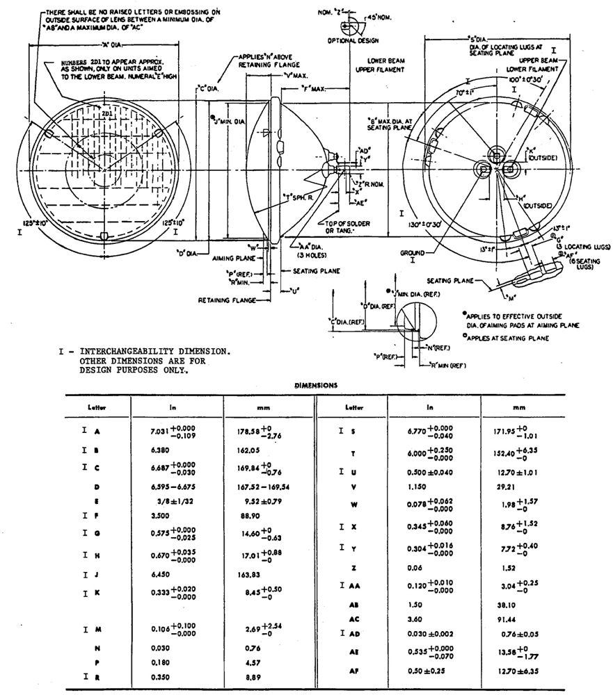
FIG. 5—HEADLAMP 178 mm DIAMETER
8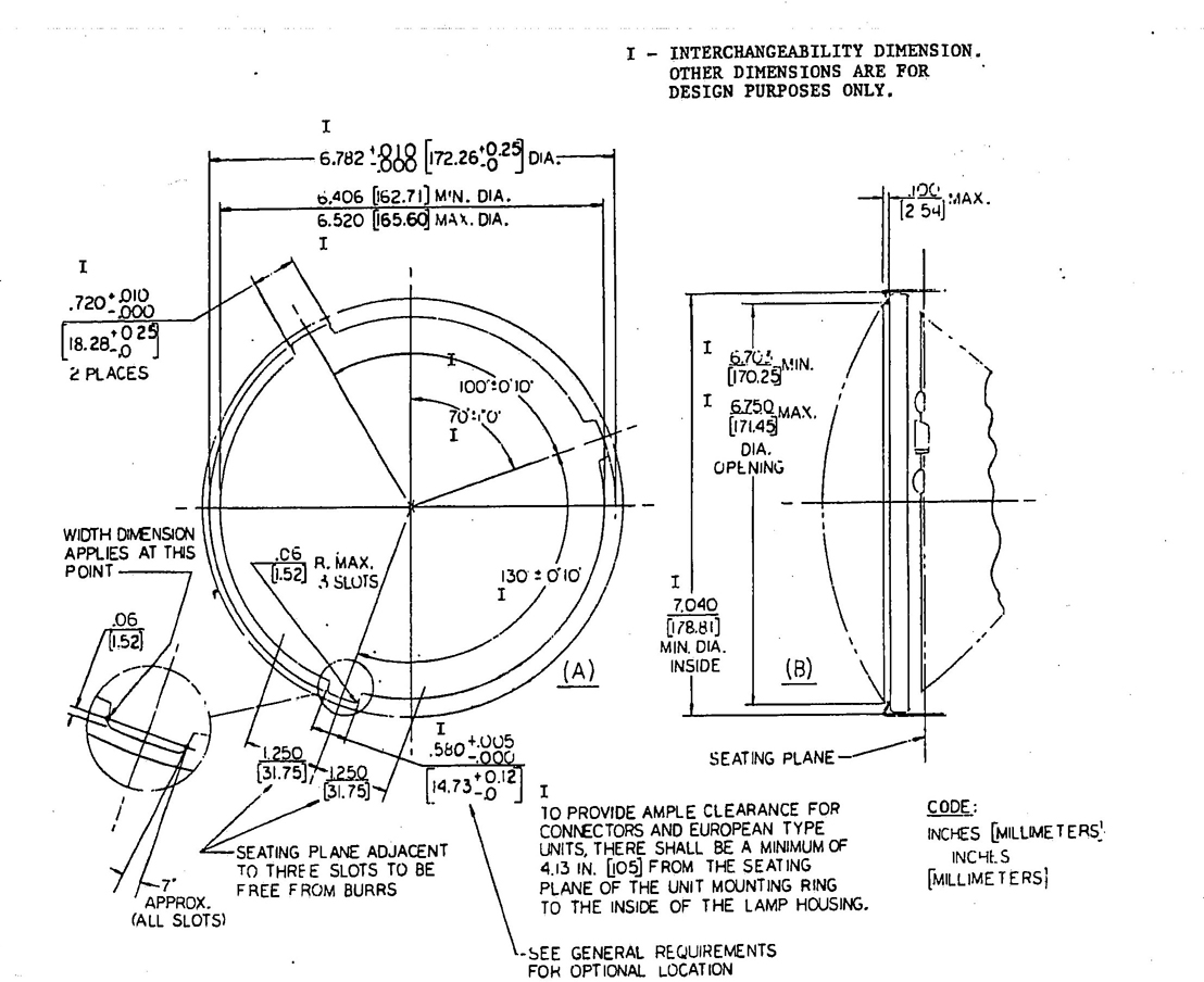
FIG. 6—(A) FRONT VIEW OF SLOT OR NOTCHES FOR 178mm DIAMETER HEADLAMP MOUNTING RING OR LAMP BODY; (B) 178 mm HEADLAMP RETAINING RING
9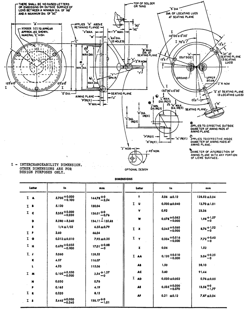
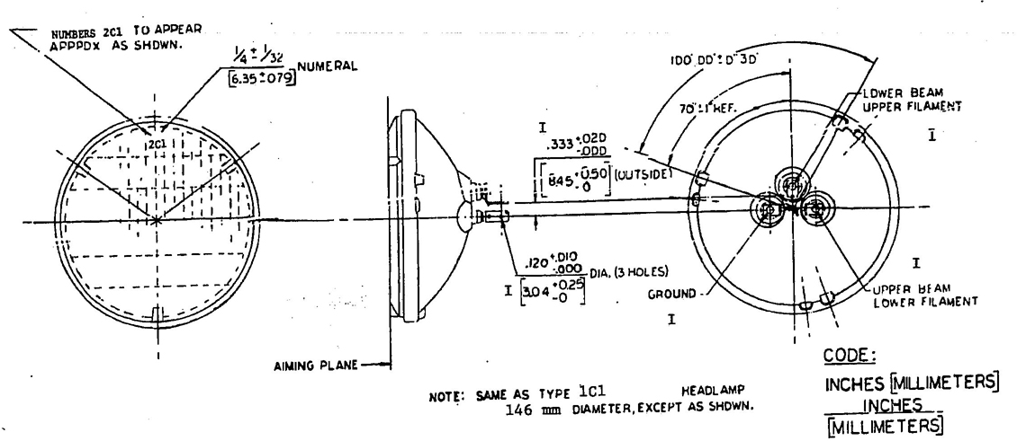
FIG. 8—TYPE 2C1 HEADLAMP UNIT 146 mm DIAMETER
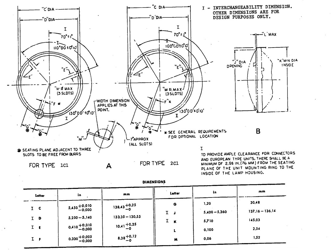
FIG. 9—(A) FRONT VIEW OF SLOTS OR NOTCHES FOR 146 mm DIAMETER HEADLAMP MOUNTING RING OR LAMP BODY; (B) 146 mm HEADLAMP RETAINING RING
11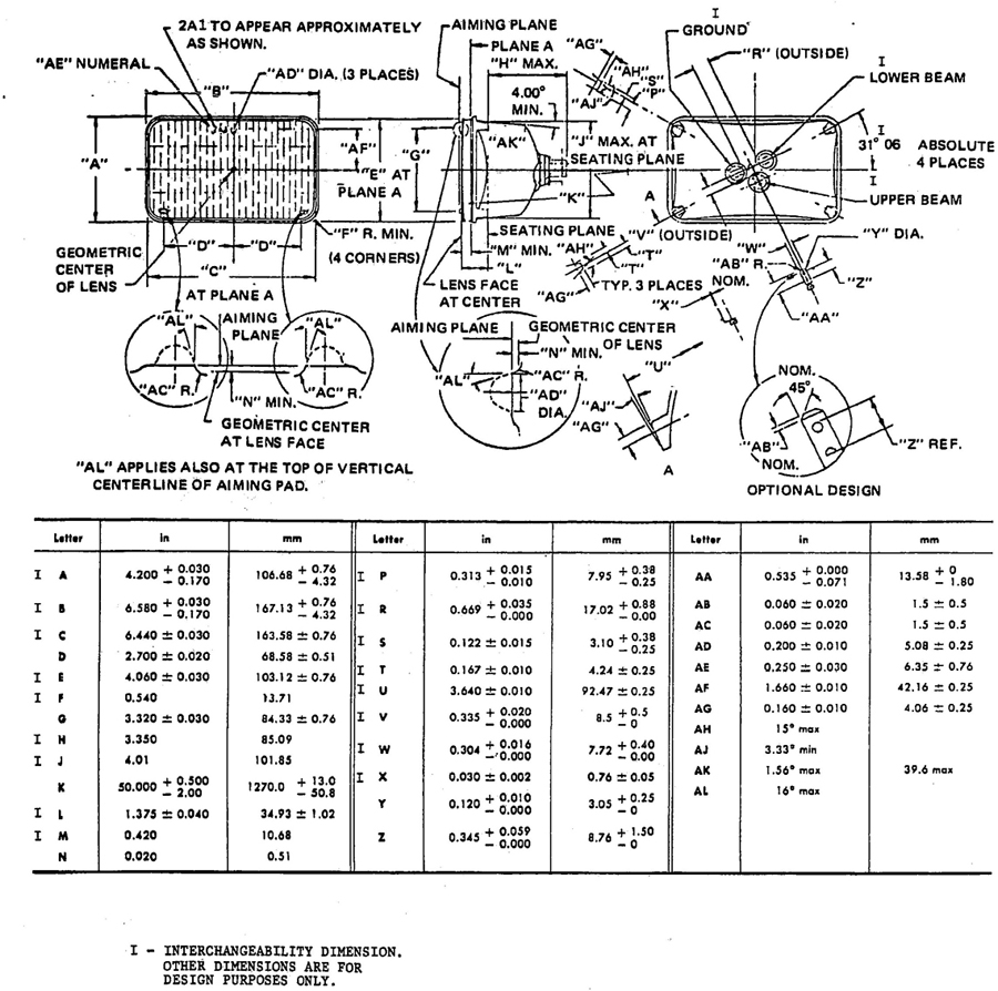
FIG. 10—TYPE 2A1 HEADLAMP 100×165 mm RECTANGULAR
12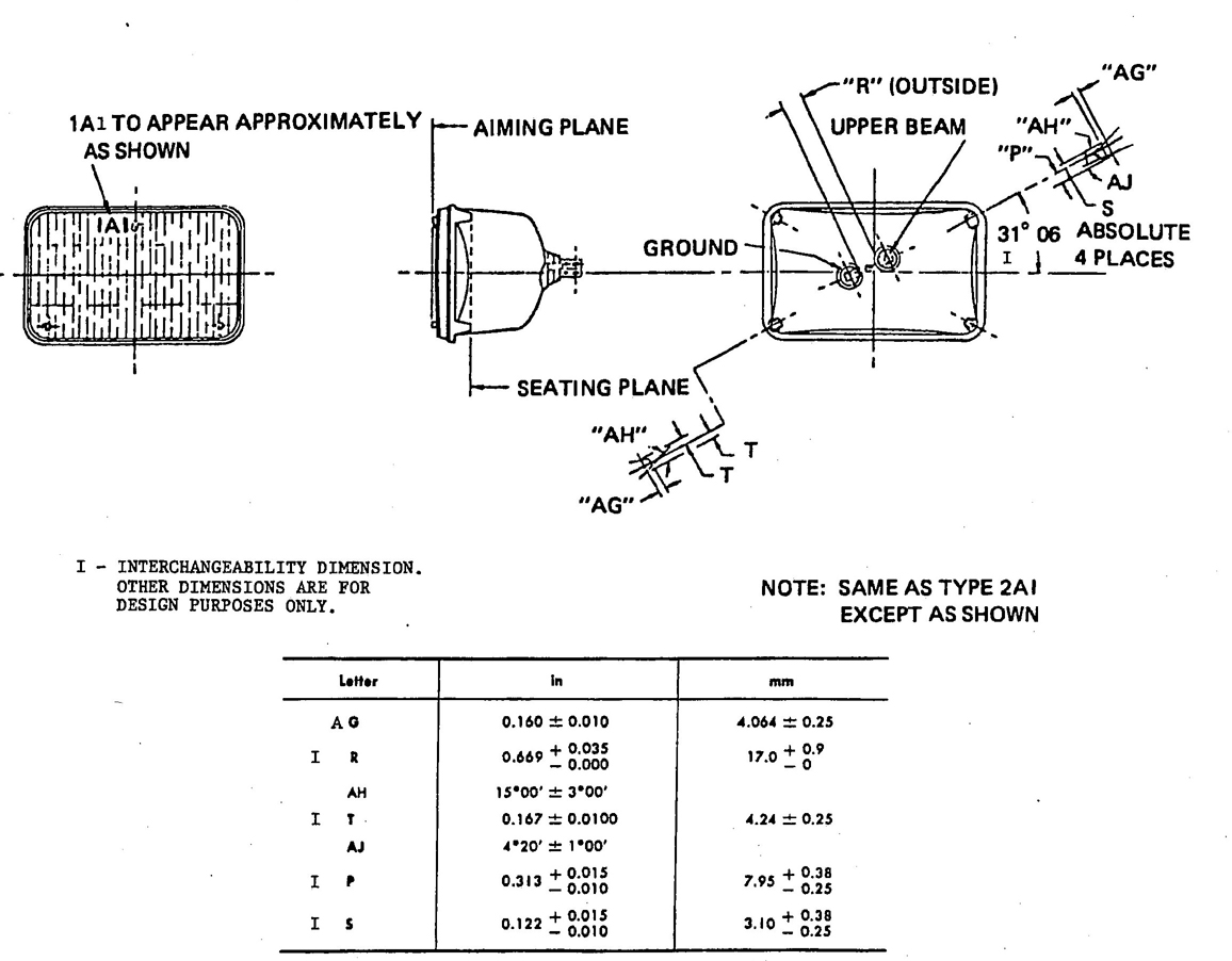
FIG. 11—TYPE 1A1 HEADLAMP 100 × 165 mm RECTANGULAR
13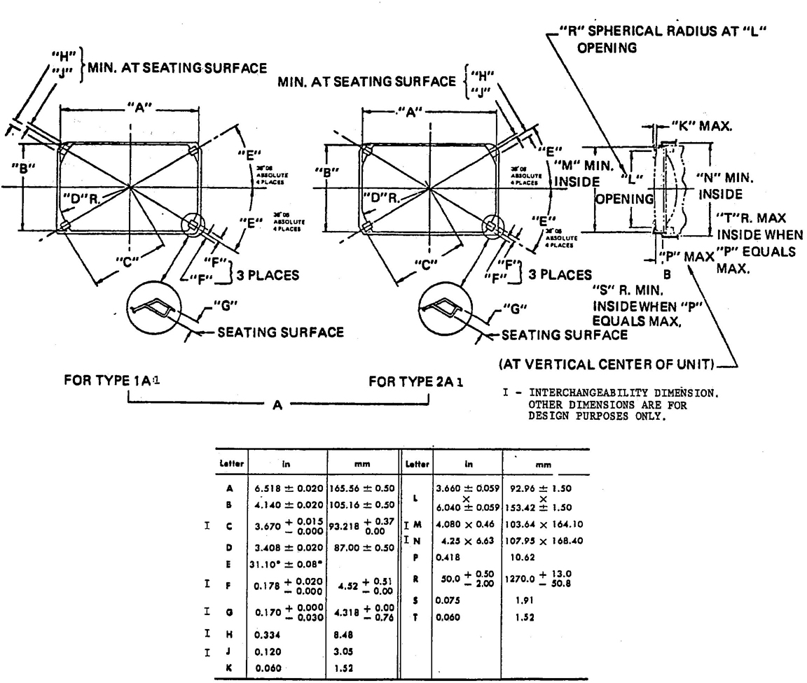
FIG. 12—(A) FRONT VIEW OF SLOTS OR NOTCHES FOR 100 × 165 mm RECTANGULAR HEADLAMP MOUNTING RING OR LAMP BODY; (B) RECTANGULAR HEADLAMP RETAINING RING
14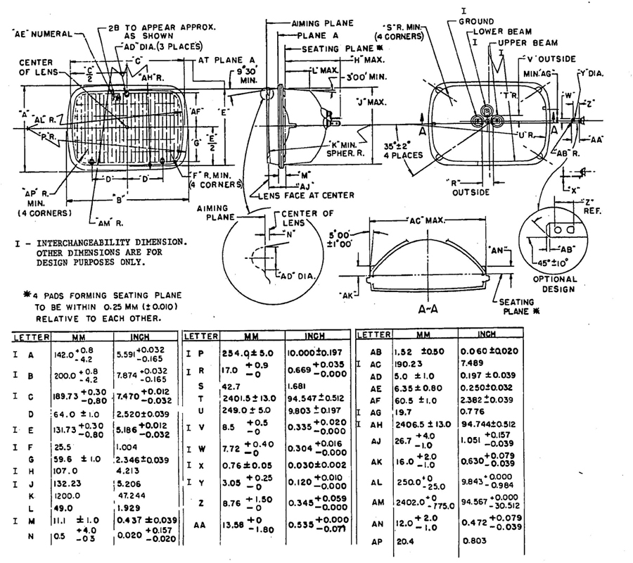
FIG. 13—TYPE 2B1 HEADLAMP 142 × 200 mm RECTANGULAR
15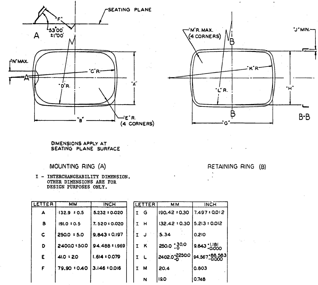
FIG. 14—(A) FRONT VIEW OF MOUNTING RING OR LAMP BODY FOR 142 × 200 mm RECTANGULAR HEADLAMP; (B) RETAINING RING
16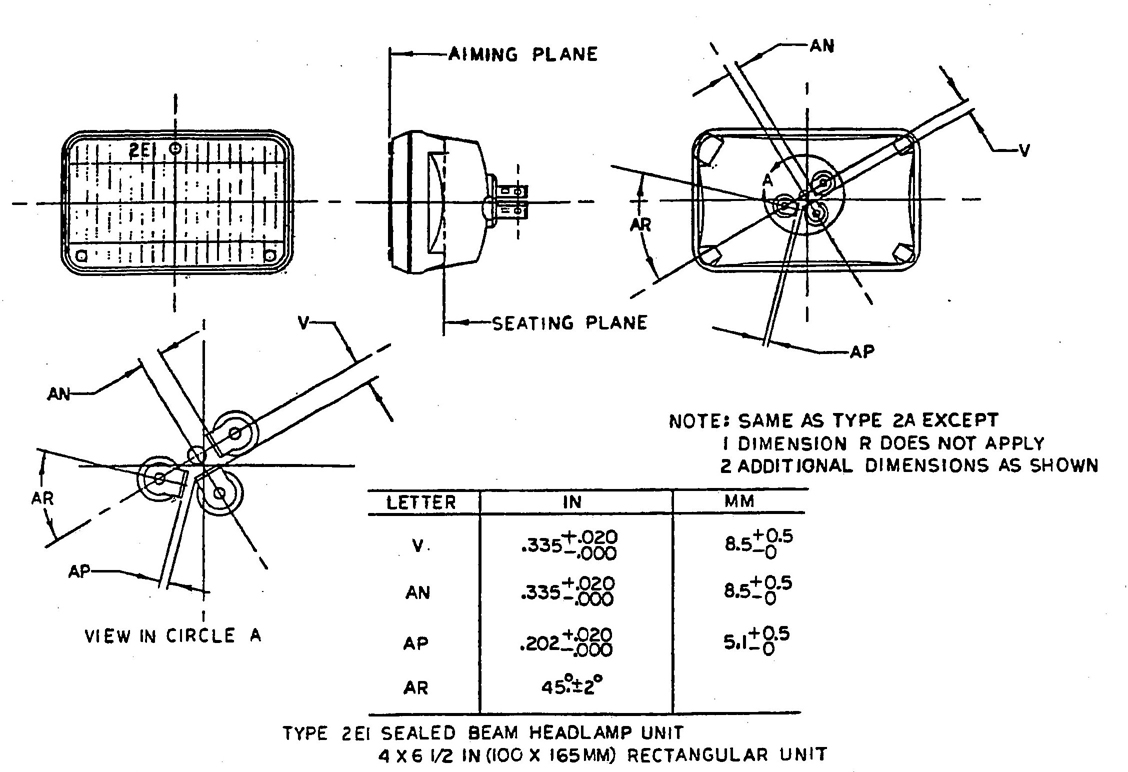
FIG. 15
| Headlamp Type and Identification Codea | Trade No.b | Design Watts at 12.8 V | Rated Avg. Lab Life at 14 Vc | Max. Amps at 12.8 V | Size mm | Dimensional Spacs. | Terminals | ||||
|---|---|---|---|---|---|---|---|---|---|---|---|
| U.B. | L.B. | U.B. | L.B | U.B. | L.B. | No. | Type | ||||
| 2C1 | 4000 | 37.5 | 60 | 200 | 320 | 3.14 | 5.02 | 146 | Fig. 7 | 3 | Lug |
| 2C1 | 4040b | 37.5 | 60 | 200 | 320 | 3.14 | 5.02 | 146 | Fig. 7 | 3 | Lug |
| 2C1 | H5006 | 35 | 35 | 200 | 320 | 2.94 | 2.94 | 146 | Fig. 7 | 3 | Lug |
| 1C1 | 4001 | 37.5 | 200 | 3.14 | 146 | Fig. 8 | 2 | Lug | |||
| 1C1 | H4001 | 37.5 | 200 | 3.14 | 146 | Fig. 8 | 2 | Lug | |||
| 1C1 | 5001 | 50 | 200 | 4.20 | 146 | Fig. 8 | 2 | Lug | |||
| 1C1 | H5001 | 50 | 200 | 4.20 | 146 | Fig. 8 | 2 | Lug | |||
| 2D1 | 6014 | 50 | 50 | 200 | 320 | 5.02 | 4.20 | 178 | Fig. 5 | 3 | Lug |
| 2D1 | H6014 | 60 | 50 | 200 | 320 | 5.02 | 4.20 | 178 | Fig. 5 | 3 | Lug |
| 2D1 | 6015b | 60 | 50 | 200 | 320 | 5.02 | 4.20 | 178 | Fig. 5 | 3 | Lug |
| 2D1 | 6016b | 60 | 50 | 300 | 500 | 5.02 | 4.20 | 178 | Fig. 5 | 3 | Lug |
| 2D1 | H6017 | 60 | 35 | 200 | 320 | 5.02 | 2.94 | 178 | Fig. 5 | 3 | Lug |
| 1A1 | 4651 | 50 | 200 | 4.20 | 100 × 165 | Fig. 11 | 2 | Lug | |||
| 1A1 | H4651 | 50 | 200 | 4.20 | 100 × 165 | Fig. 11 | 2 | Lug | |||
| 2A1 | 4652 | 40 | 60 | 200 | 320 | 3.36 | 5.02 | 100 × 165 | Fig. 10 | 3 | Lug |
| 2A1 | H4656 | 35 | 35 | 200 | 320 | 2.94 | 2.94 | 100 × 165 | Fig. 10 | 3 | Lug |
| 2A1 | H4662 | 40 | 45 | 200 | 320 | 3.36 | 4.20 | 100 × 165 | Fig. 10 | 3 | Lug |
| 2A1 | H4739 | 40 | 50 | 500 | 2000 | 3.36 | 4.20 | 100 × 165 | Fig. 10 | 3 | Lug |
| 2B1 | 6052 | 65 | 55 | 150 | 320 | 5.46 | 4.62 | 142 × 200 | Fig. 13 | 3 | Lug |
| 2B1 | H6052 | 65 | 35 | 150 | 320 | 5.46 | 4.62 | 142 × 200 | Fig. 13 | 3 | Lug |
| 2B1 | H6054 | 65 | 35 | 150 | 320 | 5.46 | 2.94 | 142 × 200 | Fig. 13 | 3 | Lug |
| 2E1 | H4666 | 65 | 45 | 150 | 320 | 5.46 | 3.78 | 100 × 165 | Fig. 10 | 3 | Lug |
| aHeadlamp identification codes are explained in paragraph 5.4. bHeavy duty headlamps. cAll headlamps designed for 12.8 V usage are life tested at 14 V. In general, the life at vehicle voltage is longer. |
|||||||||||
| Bulb Designation |
Number of Filaments |
Design Watts at 12.8V U.B./L.B.a |
Luminous Flux (Lumens) at 12.8 V U.B./L.B.b |
Rated Avg. Lab Life (hours) at 14 V U.B/L.B. |
Max. Amps at 12.8 V U.B./L.B. |
Filament Type |
Dimensional Specs. |
Filament Tolerance Specs. |
|---|---|---|---|---|---|---|---|---|
| 9004 [ANSI] | 2 | 65/45 | 1316/800 | 150/320 | 5.1/3.5 | C6/C6 | SAE XJ1496 | U-D 0.020 R-L0.020 A-B 0.015 |
| H1 | 1 | 55c | 1550c | 22.5d | 5.2c | C8 | ECE-R37 and ICE PUBL 612 | |
| H3 | 1 | 55c | 1450c | 22.5d | 5.2c | C6 | ECE-R37 and ICE PUBL 61c | |
| H4 | 2 | 60/55c | 1650/1000c | 200/400d | 5.7/5.2c | C8/C8 | ECE-R-37 and ICE PUBL 612 | |
| aWattage and lumen measurements shall be made with the direct current test voltage regulated within 1/4 at 1%. The bulb filaments shall be subject to seasoning prior to wattage and lumen measurement. bWith black cap ±10%. cAt 13.2 V. dMinimum rated value at 13.2 V. eECE regulation 37, United Nations publication may be obtained from bookstores and distributors. Also available from United Nations, Sales Section, New York, NY. ICE Regulation 61, ICE Standard, “Lamp Cap and Holders Together with Gauges,” may be obtained from ANSI or Information Handling Services, Denver, CO. |
||||||||
This report is published by SAE to advance the state of technical and engineering sciences. The use of this report is entirely voluntary, and its applicability and suitability for any particular use, including any patent infringement arising there from, is the sole responsibility of the user.
PRINTED IN U.S.A.
18