
In order to promote public education and public safety, equal justice for all, a better informed citizenry, the rule of law, world trade and world peace, this legal document is hereby made available on a noncommercial basis, as it is the right of all humans to know and speak the laws that govern them.
INTERNATIONAL STANDARD
ISO
11660–3
Second edition
2008–02–15
Appareils de levage à charge suspendus — Moyens d'accès, dispositifs de protection et de retenue—
Partie 3: Grues à tour
Reference number
ISO 11660-3:2008(E)
© ISO 2008
ii| PDF disclaimer |
| This PDF file may contain embedded typefaces. In accordance with Adobe's licensing policy, this file may be printed or viewed but shall not be edited unless the typefaces which are embedded are licensed to and installed on the computer performing the editing. In downloading this file, parties accept therein the responsibility of not infringing Adobe's licensing policy. The ISO Central Secretariat accepts no liability in this area. Adobe is a trademark of Adobe Systems incorporated. Details of the software products used to create this PDF file can be found in the General Info relative to the file; the PDF-creation parameters were optimized for printing. Every care has been taken to ensure that the file is suitable for use by ISO member bodies. In the unlikely event that a problem relating to it is found, please inform the Central Secretariat at the address given below. |
 COPYRIGHT PROTECTED DOCUMENT
© ISO 2008
All rights reserved. Unless otherwise specified, no part of this publication may be reproduced or utilized in any form or by any means, electronic or mechanical, including photocopying and microfilm, without permission in writing from either ISO at the address below or ISO's member body in the country of the requester.
ISO copyright office
Case postale 56 • CH–1211 Geneva 20
Tel. + 41 22 749 01 11
Fax + 41 22 749 09 47
E-mail copyright@iso.org
Web www.iso.org
Published in Switzerland
iiiISO (the International Organization for Standardization) is a worldwide federation of national standards bodies (ISO member bodies). The work of preparing International Standards is normally carried out through ISO technical committees. Each member body interested in a subject for which a technical committee has been established has the right to be represented on that committee. International organizations, governmental and non-governmental, in liaison with ISO, also take part in the work. ISO collaborates closely with the International Electrotechnical Commission (IEC) on all matters of electrotechnical standardization.
International Standards are drafted in accordance with the rules given in the ISO/IEC Directives, Part 2.
The main task of technical committees is to prepare International Standards. Draft International Standards adopted by the technical committees are circulated to the member bodies for voting. Publication as an International Standard requires approval by at least 75% of the member bodies casting a vote.
Attention is drawn to the possibility that some of the elements of this document may be the subject of patent rights. ISO shall not be held responsible for identifying any or all such patent rights.
ISO 11660–3 was prepared by Technical Committee ISO/TC 96, Cranes, Subcommittee SC 7, Tower cranes.
This second edition cancels and replaces the first edition (ISO 11660–3:1999), which has been technically revised.
ISO 11660 consists of the following parts, under the general title Cranes— Access, guards and restraints:
— Part 1: General
— Part 2: Mobile cranes
— Part 3: Tower cranes
— Part 5: Bridge and gantry cranes
iv vCranes — Access, guards and restraints—
Part 3:
Tower cranes
This part of ISO 11660 establishes the particular requirements relating to access, guards and restraints for tower cranes as defined in ISO 4306–3.
ISO 11660-1 establishes the general requirements for access to control stations and other areas of cranes as defined in ISO 4306–1, during normal operations, maintenance, inspection, erection and dismantling. It also deals with guards and restraints in general, concerning the protection of persons on or near the crane with regard to moving parts, falling objects or live parts.
The following referenced documents are indispensable for the application of this document. For dated references, only the edition cited applies. For undated references, the latest edition of the referenced document (including any amendments) applies.
ISO 11660–1:2008, Cranes — Access, guards and restraints — Part 1: General
ISO 13852, Safety of machinery — Safety distances to prevent danger zones being reached by the upper limbs
For the purposes of this document, the terms and definitions given in ISO 11660–1 apply.
All control stations and all other parts of the crane, requiring inspection or regular maintenance shall be accessible by means of stairs, ladders, gangways and landings.
In order to carry out erection or dismantling operations, inspection, routine maintenance or replacement of parts located above the ground, the tower crane, including the jib, shall be provided with support equipment such as hand rails, hand grips, platforms, safety equipment, etc. to ensure the safety of personnel and to allow them access to places of work.
1The design requirements for access shall comply with the clauses/subclauses of ISO 11660-1:2008 specified in Table 1, as completed by the corresponding subclauses of this part of ISO 11660 specified in the same table.
| Applicable clause/subclause in ISO 11660-1:2008 | Topic | As completed by applicable clause in this part of ISO 11660 |
|---|---|---|
| 5.8 | Crushing hazard between moving parts | 4.2.1.2 |
| 6 | Stairs | 4.2.1.3 |
| 7 | Rung ladders | 4.2.1.4 |
| 9 | Manholes and hatched apertures | 4.2.1.5 |
Where persons could be present between moving parts, a safety distance of at least 0,5m shall be observed. Where such a distance cannot be obtained, guards (when possible) and warning notices shall be fitted.
In addition to the dimensions given in ISO 11660-1, the recommended dimensions for steps are as follows:
— rise: 200 mm;
— clear width: 500 mm.
For all types of tower cranes, the first flight of ladder may be no greater than 10 m.
In addition, for self-erecting cranes, the following applies.
— Flights of type 1 ladders shall be positioned in such a way as to prevent persons from falling more than 10 m.
— Type 1 ladders shall have rest platforms at least every 10 m.
— Evacuation of an elevating control station in the event of power failure, etc. shall be possible by alternative means of egress. When a ladder is used for this purpose, the dimensions defined in ISO 11660-1 are not applicable. With reference to ISO 11660-1:2008, Table 4, the step width, m, may be reduced to 0,2 m, and the distance between the centre line of the rung and vertical surface, d, may be reduced to 0,1 m, allowing the use of the rung at least by one foot.
2If the crane construction does not allow larger dimensions:
— for type 1 access in accordance with ISO 11660-1:2008, the minimum dimensions for effective hatch apertures shall be (0,55 × 0,55) m for top-slewing cranes and (0,50 × 0,50) m for self-erecting cranes;
— for type 2 access in accordance with ISO 11660-1:2008, the minimum dimensions for effective hatch apertures shall be (0,50 × 0,40) m.
If it is not possible to lower the jib to the ground to carry out a visual inspection of it, a basket fixed to the trolley shall be provided. In addition, a walkway incorporating the following shall be fixed along the jib to reach the mechanism(s):
— side protection, or
— personal protective device against the falls.
When the basket cannot be used during erection/dismantling, repair or maintance, the use of a personal protective device against the falls shall be possible all along the jib.
The width of the walkway shall comply with ISO 11660-1:2008, Table 6, type 2.
When the size of the jib is sufficient to walk inside the jib (i.e. the dimension between the walkway and the upper member is equal to or greater than 1,8 m), toe boards shall be provided on each side of the walkway with a minimum height of 0,03 m. When the dimension between the walkway and the upper member is less than 1,8 m, a toe board is provided only on one side (see Figure 1).
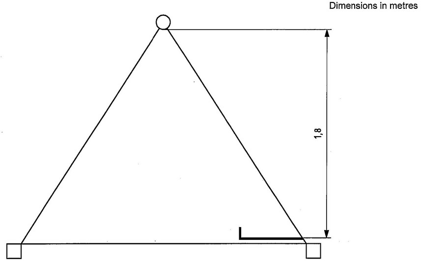
Figure 1—Walkway with toe board on one side
3Manufacturers shall take into consideration the dimension of the jib when determining the position of the walkway, hand rail and steel wire rope.
The minimum dimension of the length/width of the basket shall be (0,50 × 0,35) m.
Manufacturers shall take into consideration the mass and the number of persons when determining the basket.
The side protection shall comply with ISO 11660-1:2008, Table 7, type 2, walkway.
Instructions and markings shall be provided for the use of the basket on the following:
— how to reach the basket;
— the admissible load and number of persons;
— warnings concerning residual risks, e.g. shearing, entanglement.
During the access to the control station, moving parts shall be guarded by safety distances as defined in ISO 13852, or by provision of removable or fixed guards.
The guards that may be used on walkways or work platforms shall be designed for this use (see ISO 11660-1).
If the crane construction does not permit such guards, warnings shall be provided, e.g.
— in top slewing cranes, in limited space areas within the connection between slewing ring support, slewing ring and slewing platform;
— in self-erecting cranes, between undercarriage, slewing ring and machinery platform.
Crane parts such as gears, pulleys, trolley wheels, covers and boxes shall be designed, assembled and fixed in such a way as to prevent them from falling during normal operation.
Covers, guards and access closures shall be fitted with hinges or other means to prevent them from falling.
The trolleys shall be designed such that:
— the wheels will not slip out from the railway in case of rupture of the axis, and
— it shall not be possible for the trolley to fall.
The output gears of the slewing gears shall be provided with covers or another device to prevent them from falling in case of rupture.
4ICS 53.020.20
Price based on 5 pages
6