
In order to promote public education and public safety, equal justice for all, a better informed citizenry, the rule of law, world trade and world peace, this legal document is hereby made available on a noncommercial basis, as it is the right of all humans to know and speak the laws that govern them.
INTERNATIONAL STANDARD
ISO
11660-2
First edition
1994-08-15
Appareils de levage a charge suspendue — Moyens d'acces, dispositifs de protection et de retenue —
Partie 2: Grues mobiles
Reference number
ISO 11660-2:1994(E)
ISO (the International Organization for Standardization) is a worldwide federation of national standards bodies (ISO member bodies). The work of preparing International Standards is normally carried out through ISO technical committees. Each member body interested in a subject for which a technical committee has been established has the right to be represented on that committee. International organizations, governmental and non-governmental, in liaison with ISO, also take part in the work. ISO collaborates closely with the International Electrotechnical Commission (IEC) on all matters of electrotechnical standardization.
Draft International Standards adopted by the technical committees are circulated to the member bodies for voting. Publication as an International Standard requires approval by at least 75% of the member bodies casting a vote.
International Standard ISO 11660-2 was prepared by Technical Committee ISO/TC 96, Cranes, Subcommittee SC 6, Mobile cranes.
ISO 11660 consists of the following parts, under the general title Cranes—Access, guards and restraints:
—Part 1: General
—Part 2: Mobile Cranes
—Part 3: Tower cranes
—Part 4: Jib cranes
Annexes A and B of this part of ISO 11660 are for information only.
© ISO 1994
All rights reserved. Unless otherwise specified, no part of this publication may be reproduced
or utilized in any form or by any means, electronic or mechanical, including photocopying and
microfilm, without permission in writing from the publisher.
International Organization for Standardization
Case Postale 56 • CH–1211 Geneve 20 • Switzerland
Printed in Switzerland
iiiCranes — Access, guards and restraints —
Part 2: Mobile cranes
This part of ISO 11660 specifies criteria for steps, stairways, ladders, walkways, platforms, handrails, handholds, guardrails and entrance openings which permit access to and from operator, inspection or maintenance platforms on mobile cranes as defined in ISO 4306–2 and parked in accordance with the manufacturer's instruction. It also presents requirements for guards and restraints as related to moving parts.
This part of ISO 11660 is also based on and partly in harmony with ISO 2860 and ISO 2867. For mobile cranes fitted with a tower ISO 11660–3 and ISO 11660–4 should be consulted.
The following standards contain provisions which, through reference in this text, constitute provisions of this part of ISO 11660. At the time of publication, the editions indicated were valid. All standards are subject to revision, and parties to agreements based on this part of ISO 11660 are encouraged to investigate the possibility of applying the most recent editions of the standards indicated below. Members of IEC and ISO maintain registers of currently valid International Standards.
ISO 4306–2:—1), Cranes —Vocabulary—Part 2: Mobile cranes.
ISO 11660–1:—2), Cranes — Access, guards and restraints — Part 1: General.
3.1 The requirements given in this part of ISO 11660 are based on one person, unladen, using the access system by himself, i.e. no other coworkers are on the access system, and on the 95th to 5th percentile human physical dimensions as presented in ISO 3411.
It shall also be recognized that some machine designs may require modifications or variances from the requirements presented in this part of ISO 11660.
For the purposes of this part of ISO 11660, the following definitions apply.
4.1 access system: System provided on a machine for entrance to and exit from an operator, inspection or maintenance platform from and to the ground.
1) To be published. (Revision of ISO 4306-2:1985)
2) To be published.
1The primary access system is the access system normally used, while the alternative access system is the access route used during anticipated emergency situations when the primary access system cannot be used.
4.2 JIb walkway: Walkway used mainly on long jibs, such as on dragline cranes, which are inclined at angles up to 20° from the horizontal.
4.3 jib skywalk platform: Maintenance platform on jib base sections.
4.4 controlled descent device: Device which can automatically lower a person without power at a fixed speed as part of an alternative access system.
4.5 enclosure opening: Opening leading to or from an access system and large enough for a person to pass through.
4.5.1 primary opening: Opening normally used for access.
4.5.2 alternative opening: Opening for use during emergencies when the primary opening is not usable.
4.5.3 service opening: Opening for use during maintenance, service or inspection.
4.6 foot barrier: Device to prevent a person's foot from slipping off the edge of a platform or walkway.
4.7 guardrail: Device along the open sides of walkways or platforms to protect a person from falling.
4.8 handrail and handhold: Parts of an access system that may be grasped by the hand as an aid to body support and balance.
4.9 ladder: Access system or part of an access system, inclined from the horizontal at an angle greater than 50° but not more than 90°, consisting of a series of equally spaced steps that can accommodate one or both feet.
4.9.1 vertical ladder: Ladder whose angle of inclination from the horizontal is greater than 75°.
4.9.2 inclined ladder: Ladder whose angle of inclination from the horizontal is greater than 50° but not more than 75°.
4.9.3 rung ladder: Ladder consisting of side rails and rungs which can accommodate both feet, used for access where the angle of inclination from the horizontal exceeds 75°.
4.9.4 stepped ladder: Ladder consisting of side rails and steps which can accommodate both feet, used for access where the angle of inclination from the horizontal exceeds 65°.
4.10 ladder fall-limiting device: Any device which minimizes or limits the length of fall from a ladder system.
4.11 operator's platform: Area from which an operator controls the travel and work functions of the machine.
4.12 passageway: Walkway with confining barriers on both sides that extend vertically above the walking surface to a height of at least 1 200 mm for erect walking or 300 mm for crawling.
4.13 platform: Horizontal surface for the support of persons engaged in operation, maintenance, inspection or repair work.
4.14 ramp: Plane inclined at an angle of 20° or less from the horizontal, without steps, but with cleats or other surface treatment for the purpose of traction.
4.15 cleat: Device added to a walkway or ramp surface to improve traction.
4.16 rest platform; landing: Platform used in conjunction with a ladder system for a person to rest on while standing.
4.17 riser height: Height between two consecutive steps or rungs, measured from the tread surface of one step or rung to the tread surface of the next.
4.18 rung: Device on which one or both feet may be placed, generally installed on vertical ladders or on a single foot-step.
4.19 stairway: Access system or part of an access system inclined from the horizontal at an angle greater than 33,7° but not more than 67° and consisting of four or more steps.
4.20 step: Device for placement of one or both feet, either as part of a ladder or stairway, or installed (placed) individually.
4.21 stride distance: Horizontal distance from the leading edge of one step to the leading edge of the next step.
4.22 three-point support: Feature of an access system which permits, but does not require, a person to use simultaneously two hands and one foot or two
2feet and one hand, while ascending, descending or moving about on the crane.
4.23 tread depth: Distance from the leading edge to the back of the step.
4.24 walkway: Part of an access system that permits walking or crawling between locations on a crane.
4.25 powered or manually actuated access device: Device that through power or manual actuation provides a complete or partial primary access or alternative access system.
4.26 slip-resistant surface: Access system surface having qualities which improve the traction obtained by the foot.
Annex A presents examples of surfaces that are considered “slip-resistant”.
5.1 Access system design shall consider:
5.2 Primary access system devices may be portable for convenient storage on the crane but shall be capable of being positively secured when in use or in the stored position.
5.3 An alternative exit shall be provided and shall be clearly indicated if not obvious.
6.1 The walking and standing surfaces of access systems shall withstand, without visible permanent deformation, the following minimum forces applied perpendicular to the surface.
These forces need not be applied simultaneously.
6.2 Openings in walkways and platform surfaces shall not permit the passage of a spherical object of diameter ≥ 40 mm. If the floor surface is above a surface where persons will be walking, standing or working, the opening shall not permit the passage of a spherical object of diameter ≥ 20 mm. Solid surfaces shall be used when necessary to prevent the passage of material that could result in personal injury to a person above or below the surface. For jib walkways and other similar areas that are used only for inspection or maintenance, the standing or stepping surface openings may be increased to twice the above values.
6.3 Handrails, handholds and guardrails shall be capable of withstanding a minimum force of 1 000 N applied at any point from any direction without visible permanent deformation. Flexible devices shall not deflect under the applied test load more than 80 mm from their normal undeflected position.
6.4 Machinery enclosure roofs used only for support of personnel during inspection, such as cab and canopy roofs, may comply only with 6.1 a).
6.5 All surfaces of the access system for e.g. walking, stepping or crawling (including any device or structural component thereof used as part of an access system) shall be slip-resistant.
Crane track shoe and track pad surfaces can be used as access steps if three-point support is provided.
37.1 Steps shall conform to the dimensions given in figure 1 and table 1. Where possible, steps should be wide enough to accommodate both feet.
7.2 Where lateral body movement is necessary from the top or bottom step of a ladder to the next stepping surface, the distance between the rung and the nearest edge of the bearing surface shall be within a spherical radius R of 300 mm max. (see figure 1).
7.3 Steps shall be coordinated with properly positioned handrails and handholds.
7.4 Wherever a foot can protrude through the step and contact a moving part, a shield shall be provided between the step and the moving part.
7.5 Step design should incorporate a barrier at the ends of the step which the foot will contact in the event of lateral slippage.
7.6 The step tread surface shall not be intended for use as a handhold.
7.7 Step design should minimize accumulation of debris and aid in the cleaning of mud and debris from the shoe sole. Crawler tracks, if permitted as steps, do not meet this requirement.
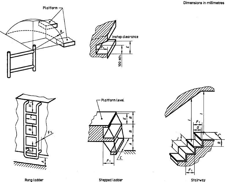
Figure 1 — Steps, ladders and stairways
4| Dimensions in millimetres | |||
|---|---|---|---|
| Symbol | Description | Dimension | |
| min. | max. | ||
| A | Height of first step above ground or platform | — | 600 |
| B | Riser height | ||
| Rung ladders | 230 | 400 | |
| Steps (stepped ladders, stairs, etc.) | 180 | 250 | |
| C | Step width | ||
| Ladders | |||
| for one foot | 160 | — | |
| for both feet | 320 | — | |
| Stairway | 320 | — | |
| D | Rung tread — diameter or width | 19 | 40 |
| E | Instep clearance | 150 | — |
| F1 | Tread depth | ||
| Steps (stepped ladders, stairways, etc.) | 2401) | 400 | |
| F2 | Toe clearance (free space behind rungs) | 150 | — |
| G | Stride distance2) | 130 | 270 |
| H | Distance from top rung of ladder to platform level | — | 150 |
| I | Head clearance above step leading to walkway | 2 000 | — |
| J | Step placement (stair) (2B + G) | 630 | |
| R | Step placement from ladder | — | 300 |
| 1) See 9.3; can be reduced to 130 when free space for toe clearance is provided. | |||
| 2) The formula given for J shall always be satisfied. | |||
7.8 Step design shall, as far as is practical, provide the user with natural foot placement while descending, or steps shall be clearly visible to the user while descending.
NOTE 1 Natural foot placement of steps does not ensure user confidence. Only familiarity with the access system can instill confidence.
7.9 Flexibly-mounted series of steps be should be avoided. If used, the steps shall not move more than 80 mm elastically in any plane when a horizontal force of 1 000 N is applied centred on the outer edge of the leading edge of the first nonswinging step from the ground. The first step from the ground may be free-swinging.
8.1 Ladder steps shall meet the criteria specified in clause 7.
8.2 Vertical ladders which extend more than 5 m vertically above ground level shall be equipped with a ladder fall-limiting device, preferably of the passive type. Such a device shall not require continual manipulation for the user to ascend or descend the ladder.
8.2.1 The lower end of a ladder cage or other similar device, if used, shall be a maximum of 3 m above ground or platform level.
58.2.2 The internal surface of a ladder cage on a vertical ladder shall not extend more than 700 mm from the steps nor shall its internal width be more than 700 mm.
8.3 A rest platform shall be provided at least every 10 m of vertical climb.
8.4 Winding or spiral ladders of vertical height >3 m shall be provided with open-side guardrails.
9.1 Stairways shall be provided with at least one handrail.
9.2 Stairways with a vertical drop >3 m shall be provided with guardrails on the open side or sides.
9.3 Step tread depth on stairways shall be equal to or greater than the riser height. Successive riser heights and successive step tread depths shall be of uniform dimensions.
9.4 Stairway steps shall met the criteria specified in clause 7.
10.1 Handrails and handholds shall conform with the dimensions specified in figure 2 and table 2.
10.2 Handrails and handholds shall be appropriately placed along the access system to provide continuous support to a moving person and to enable users to maintain their balance.
10.3 The preferred cross-section of a handrail and handhold is circular. A square or rectangular cross-section with rounded corners is permissible.
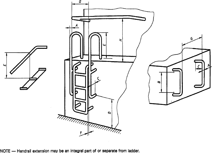
Figure 2 — Handrails and handholds
6| Dimensions in millimetres | |||
|---|---|---|---|
| Symbol | Description | Dimension | |
| min. | max. | ||
| A | Width (diameter or across flats) | ||
| Ladder, step or walkway | 161) | 38 | |
| Stairway and ramp handrails | 16 | 80 | |
| B | Length between bend radii for support legs of handholds | 150 | — |
| C | Hand clearance to mounting surface | 75 | — |
| D | Distance above standing surface | — | 1 600 |
| E | Vertical distance of handrail continuation above step, platform, stairway or ramp | 850 | 960 |
| F | Offset distance of handrail or handhold from edge of step | 75 | 200 |
| G | Width between parallel handrails | ||
| Ladder | — | 6002) | |
| Stairway and ramp | 460 | — | |
| H | Distance above walkway, passageway, step or stairway step | 850 | 1 400 |
| 1) 19 mm if orientation is vertical. | |||
| 2) 600 mm apart if hip clearance is required. | |||
10.4 Any handrail or handhold on which the handgrasp surface extends beyond the support shall have a change of shape at the end of the handgrasp surface to help prevent the hand from slipping off the end.
10.5 The use of handrails on a ladder system is preferred to handholds. Where handholds are used, their spacing shall correspond to the step spacing.
11.1 Platforms, passageways, walkways, guardrails and foot barriers shall conform with the dimensions specified in figure 3 and table 3. A rail shall be placed midway between the top rail of a guardrail and the walkway or platform.
11.2 Platforms shall be provided with guardrails if the vertical drop from the open side of the platform surface is >3 m. Certain crane roofs may not meet this requirement if transportability factors interfere.
11.3 Walkways shall be provided with handholds, handrails or guardrails. Guardrails shall be provided if the vertical drop from the open side of the walkway surface is >3 m.
11.4 Walkways used only for access to service and inspection platforms ≤ 3 m above ground level may have a minimum width of 230 mm. Service and inspection may be performed from the walkway if this can be readily performed while maintaining three-point support.
11.5 Where an opening has been provided in a guardrail, other than to provide access to a ladder or to steps, a device shall be provided across the opening that meets the requirements of 6.3.
11.6 Wherever a foot may slip from a walkway or platform into moving machinery or equipment, a foot barrier shall be provided.
7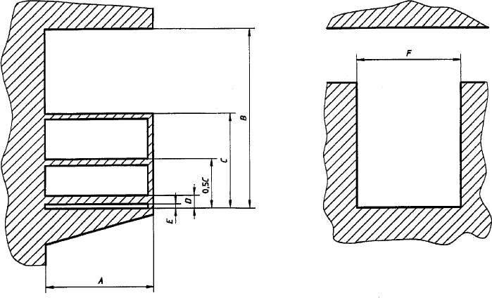
Figure 3 — Platforms, passageways, walkways and guardrails
| Dimensions in millimetres | |||
|---|---|---|---|
| Symbol | Description | Dimension | |
| min. | max. | ||
| A | Width | ||
| Platform | 600 | — | |
| Walkway1) | 450 | — | |
| B | Head clearance | ||
| Standing | 2 000 | — | |
| Kneeling2) | 1 500 | — | |
| Crawling2) | 1 000 | — | |
| C | Guardrail height | 1 000 | 1 100 |
| D | Foot barrier height3) | 50 | — |
| E | Foot barrier to floor clearance | 0 | 10 |
| F | Passageway | ||
| Forward-facing passage of user | 550 | — | |
| Sideways passage of user | 330 | — | |
| Users passing from opposite directions | 900 | — | |
| 1) The width may be reduced locally to 400 mm to allow for obstructions within the access way. | |||
| 2) For inspection and maintenance only. | |||
| 3) In special cases where it is necessary for a person to transfer, the maximum height of the foot barrier shall be limited to 500 mm at the transfer position. | |||
12.1 Enclosure openings shall conform with the dimensions specified in figure 4 and table 4.
12.2 If a rectangular opening is not possible, the minimum opening area may be reduced to the minimum dimensions indicated in figure 4. Alternatively, the vertical distance from the floor of the lower (narrower) area of the minimum opening can be increased from 460 mm to 770 mm max, in conjunction with an increase in the minimum width from 250 mm to 300 mm.
12.3 The primary opening shall be accessible directly from the access steps or from a platform or walkway.
12.4 The door of the enclosure shall be openable without infringing on the standing position of the person opening it.
12.5 An alternative opening shall be provided in the enclosure on a surface other than that of the primary access opening.
12.6 The force needed to open or close a properly functioning hinged enclosure door or cover should not exceed 135 N.
12.7 An enclosure door that may be left open during machine operation shall be provided with a means to secure it in the open position.
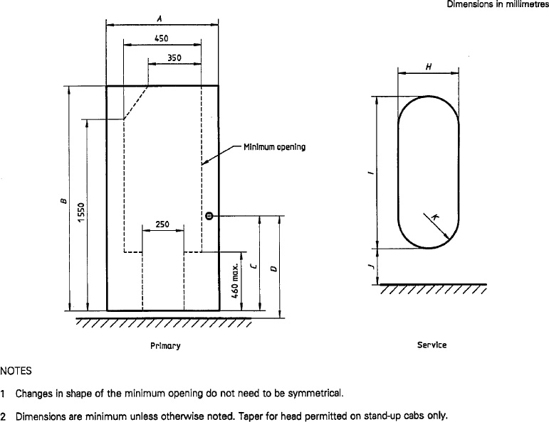
Figure 4 —Enclosure openings
9| Dimensions in millimetres | |||
|---|---|---|---|
| Symbol | Description | Dimension | |
| min. | max. | ||
| Primary opening | |||
| A | Width | 450 | — |
| B | Height | ||
| Sit-down cab | 1 300 | — | |
| Stand-up cab | 1 800 | — | |
| C | Height of internal door handle from floor | ||
| Sit-down cab | 350 | 850 | |
| Stand-up cab | 800 | 1 000 | |
| D | Height of external door handle above standing surface | 500 | 1 5001) |
| Alternative opening (preferably same size as primary opening) | |||
| Round (diameter) | 650 | — | |
| Square | 600 × 600 | — | |
| Rectangular | 470 × 650 | — | |
| Service openings | |||
| H | Width | 450 | — |
| I | Height | 760 | — |
| J | Bottom edge to floor | — | 500 |
| K | Corner radius | — | 0.5H |
| 1) 1 700 mm if distance from the ground. | |||
12.8 Hinged doors shall normally open outward. Sliding doors shall be designed to prevent hazardous door movements due to inertial force caused by machine operations.
12.9 A minimum of 80 mm hand clearance shall be provided:
12.10 Removable enclosure opening covers held in place by gravity, such as manhole covers, shall be designed to prevent the possibility of their falling through the opening.
12.11 A removable enclosure opening cover shall not exceed 40 kg in mass if required to be lifted a vertical distance of up to 300 mm, with a decrease in mass of at least 5 kg for each additional 300 mm of required lift height.
13.1 The specifications in clauses 5 to 10 also apply to these devices.
13.2 Elevators and personnel hoists shall conform to the performance requirements presented in national regulations or standards.
13.3 Access device controls shall:
13.4 The design load factor shall be at least four times the maximum anticipated working load.
13.5 Uncontrolled fall resulting from failure of a fluid line or energy source shall be prevented.
13.6 Devices which operate more than 3 m above ground level shall be equipped with guardrails or side enclosures.
13.7 A capacity plate, indicating the maximum working load and maximum number of persons permitted for safe operation of the device, shall be provided which is readily visible from the device controls.
13.8 Action of the device shall be controlled to prevent rapid movements that could result in personal injury or damage to the device.
13.9 Access onto a device shall be possible only after the device has been fully deployed.
13.10 The device shall not sway in use due to the user's movements, except that during entrance or exit a maximum movement of 80 mm in any direction is permitted.
13.11 When in its stored position, the device shall be secured. A visual or acoustic warning device shall be provided to indicate when the device is not properly stored.
13.12 The crane shall be provided with an alternative access system to supplement the powered or manually actuated access device.
13.13 Controlled descent devices shall have a constant descent speed, regardless of load, which should be in the range of 1 m/s to 3 m/s for loads up to 135 kg, but even in an emergency situation, e.g. fire in the machine, shall not exceed 4.5 m/s when exit using the device occurs.
The requirements of ISO 11660-1 regarding guards and restraints shall be applied to mobile cranes.
11The following are examples of surfaces considered slip-resistant as defined in 4.26.


ICS 53.020.20
Descriptors: handling equipment, lifting equipment, mobile equipment, cranes (hoists), access facilities, safety devices, specifications, safety requirements.
Price based on 13 pages
14