
In order to promote public education and public safety, equal justice for all, a better informed citizenry, the rule of law, world trade and world peace, this legal document is hereby made available on a noncommercial basis, as it is the right of all humans to know and speak the laws that govern them.
INTERNATIONAL STANDARD
ISO
11660-1
Second edition
2008-02-15
Appareils de levage a charge suspendue — Moyens d'accès, dispositifs de protection et de retenue —
Partie 1: Généralités
Reference number
ISO 11660-1:2008(E)
© ISO 2008
ii| PDF disclaimer |
| This PDF file may contain embedded typefaces. In accordance with Adobe's licensing policy, this file may be printed or viewed but shall not be edited unless the typefaces which are embedded are licensed to and installed on the computer performing the editing. In downloading this file, parties accept therein the responsibility of not infringing Adobe's licensing policy. The ISO Central Secretariat accepts no liability in this area. Adobe is a trademark of Adobe Systems Incorporated. Details of the software products used to create this PDF file can be found in the General Info relative to the file; the PDF-creation parameters were optimized for printing. Every care has been taken to ensure that the file is suitable for use by ISO member bodies. In the unlikely event that a problem relating to it is found, please inform the Central Secretariat at the address given below. |
 COPYRIGHT PROTECTED DOCUMENT
© ISO 2008
All rights reserved. Unless otherwise specified, no part of this publication may be reproduced or utilized in any form or by any means, electronic or mechanical, including photocopying and microfilm, without permission in writing from either ISO at the address below or ISO's member body in the country of the requester.
ISO copyright office
Case postale 56 • CH-1211 Geneva 20
Tel. + 41 22 749 01 11
Fax + 41 22 749 09 47
E-mail copyright@iso.org
Web www.iso.org
Published in Switzerland
iii| Page | ||
| Foreword | iv | |
| 1 | Scope | 1 |
| 2 | Normative references | 1 |
| 3 | Terms, definitions and symbols | 1 |
| 3.1 | Terms and definitions | 1 |
| 3.2 | Symbols | 3 |
| 4 | Access | 3 |
| 4.1 | Classification of access | 3 |
| 4.2 | Selection of access | 4 |
| 5 | General requirements | 5 |
| 6 | Stairs and stepped ladders | 7 |
| 7 | Rung ladders and footholds | 8 |
| 7.1 | Rung ladders | 8 |
| 7.2 | Footholds | 12 |
| 8 | Hoop guards | 13 |
| 9 | Walkways, inclined walkways, platforms and manholes | 15 |
| 10 | Handholds, handrails, intermediate guard-rails and side protection | 17 |
| 11 | Minimum free space for walkway and inclined walkway | 18 |
| 12 | Hatch | 18 |
| 13 | Guards and restraints | 20 |
| 13.1 | Guards for moving parts | 20 |
| 13.2 | Prevention of objects from falling | 20 |
| 14 | Electrical guarding | 20 |
| Annex A (informative) Examples of surface considered to be slip-resistant | 21 | |
| Bibliography | 22 | |
ISO (the international Organization for Standardization) is a worldwide federation of national standards bodies (ISO member bodies). The work of preparing International Standards is normally carried out through ISO technical committees. Each member body interested in a subject for which a technical committee has been established has the right to be represented on that committee. International organizations, governmental and non-governmental, in liaison with ISO, also take part in the work. ISO collaborates closely with the International Electrotechnical Commission (IEC) on all matters of electrotechnical standardization.
International Standards are drafted in accordance with the rules given in the ISO/IEC Directives, Part 2.
The main task of technical committees is to prepare International Standards. Draft International Standards adopted by the technical committees are circulated to the member bodies for voting. Publication as an International Standard requires approval by at least 75% of the member bodies casting a vote.
Attention is drawn to the possibility that some of the elements of this document may be the subject of patent rights. ISO shall not be held responsible for identifying any or all such patent rights.
ISO 11660-1 was prepared by Technical Committee ISO/TC 96, Cranes, Subcommittee SC 7, Tower cranes.
This second edition cancels and replaces the first edition (ISO 11660-1:1999), which has been technically revised.
ISO 11660 consists of the following parts, under the general title Cranes—Access, guards and restraints.
— Part 1: General
— Part 2: Mobile cranes
— Part 3: Tower cranes
— Part 5: Bridge and gantry cranes
vCranes — Access, guards and restraints —
Part 1:
General
This part of ISO 11660 establishes the general requirements for access to control stations and other areas of cranes as defined in ISO 4306-1, during normal operations, maintenance, inspection, erection, dismantling and emergency. It also deals with guards and restraints in general, concerning the protection of persons on or near the crane with regard to moving parts, falling objects or live parts.
The particular requirements relating to access, guards and restraints for the various types of cranes and lifting appliances are given in ISO 11660-2, ISO 11660-3 and ISO 11660-5.
In some cases, the particular requirements may not comply with the general requirements. Different dimensions can be permitted provided an equivalent degree of protection is achieved.
The following referenced documents are indispensable for the application of this document. For dated references, only the edition cited applies. For undated references, the latest edition of the referenced document (including any amendments) applies.
ISO 4306-1, Cranes — Vocabulary — Part 1: General
IEC 60204-32, Safety of machinery — Electrical equipment of machines — Part 32: Requirements for hoisting machines
3.1 Terms and definitions
For the purposes of this document, the terms and definitions given in ISO 4306-1 and the following apply.
3.1.1
rung ladder
means of access consisting of side-rails and rungs which accommodate both feet, used where the angle of inclination to the horizontal of inclination exceeds 75°
3.1.2
stepped ladder
means of access consisting of side-rails and steps which accommodate both feet, used where the angle of inclination to the horizontal exceeds 60°
3.1.3
stair
means of access used where the angle of inclination to the horizontal does not exceed 50°
3.1.4
ramp
plane inclined at an angle of 20° or less from the horizontal, without steps
3.1.5
walkway
part of an access system, with essentially horizontal flooring, that permits walking or crawling between locations on a crane
3.1.6
rest platform
standing area for persons to rest, situated at intervals between flights of ladders or stairs
3.1.7
platform
horizontal surface for the support of persons engaged in operation, maintenance, inspection or repair work
3.1.8
handrail
device that provides continuous hand support between two locations
3.1.9
handhold
means of providing support by a single hand placement
3.1.10
toeboard
vertical plate that is placed around the perimeter of the platform to retain loose objects
3.1.11
foothold
means of providing support for one or two feet
3.1.12
manhole
access opening to allow the passage of a person and which can be fitted with a cover
3.1.13
hatch
access opening to allow the passage of a person and which is fitted with a hinged door
3.1.14
powered access system
means of access with a power source other than manual and which is used only by operators of the crane
3.1.15
personal protective equipment
any device or appliance designed to be worn or held by an individual for protection against one or more health and safety hazards
3.2 Symbols
| a | stride distance |
| b | rung end |
| c | free length for hand clearance |
| d | distance between centre line of rung and vertical surface |
| e | distance between ladder and an obstacle to the rear |
| f | distance between axis of ladder and a lateral obstacle |
| g | gap between discontinuous elements |
| h | riser height |
| i | rung pitch |
| k | rung size |
| m | step width |
| n | diameter/width of handrail/handhold |
| p | tread depth |
| q | hand clearance to mounting surface |
| r | vertical distance between lower part of handrail/handhold and floor/foothold |
| s | vertical distance between higher part of handrail/handhold and floor of platform/rest platform situated at top of ladder/stair |
| t | clearance between edge of handrail/handhold situated along ladder and edge of rung/side-rail of ladder |
| u | clearance between parallel handrails/handholds through which body must pass |
| v | distance between floor/stair and handrail/guard-rail |
| v1 | gap between top of toe board and bottom of intermediate guard-rail |
| v2 | gap between top of intermediate guard-rail and bottom of guard-rail |
| w | distance between floor and top of toe board |
| y | clearance between floor and lower edge of toe board |
| z | distance between rung and handhold/handrail |
4.1 Classification of access
For the purposes of this part of ISO 11660, the following cases apply:
4.2 Selection of access
4.2.1 Selection of the means of access
Access to control stations, machinery spaces and portions of the crane for which periodic inspection or maintenance is required shall be provided by means such as steps, stairs, ladders, gangways, landings and platforms complete with such handrails, handholds and other accessories as are necessary.
The system shall allow for safe access to cabin and walkway.
For cranes that are regularly erected and dismantled, means of access shall be provided as required for those operations. Their design shall permit performance of the work required.
For high cranes, it may be advantageous to have a powered access means to the cabin. If a powered access system is provided, the crane shall be designed to receive it. In this case, a complementary means of access of type 2 shall also be provided.
Manufacturers shall take into consideration the following when determining the means of access to be provided:
Figure 1 shows the ranges of angle for different means of access in their working position.
Provision of access should be in the following preferential order: stair, rung ladder, stepped ladder. In addition, fixed means (e.g. hoop guard, side protection) shall be preferred to personnel protective equipment.
4.2.2 Selection of the type of access
The selection of the type of access shall be as follows:
— access to control station and starting equipment: type 1 access;
— access for maintenance period more frequent than once per month: type 1 access.
In the following cases, type 2 access may be used:
NOTE For a definition of maintenance, see ISO 23815-1:2007, 3.2, “planned (preventive) maintenance”.
4.2.3 Protection against falls from height
Table 1 summarizes the various equipment as defined in Clauses 6,7 and 9, with the possible corresponding protection depending on the type of access.
4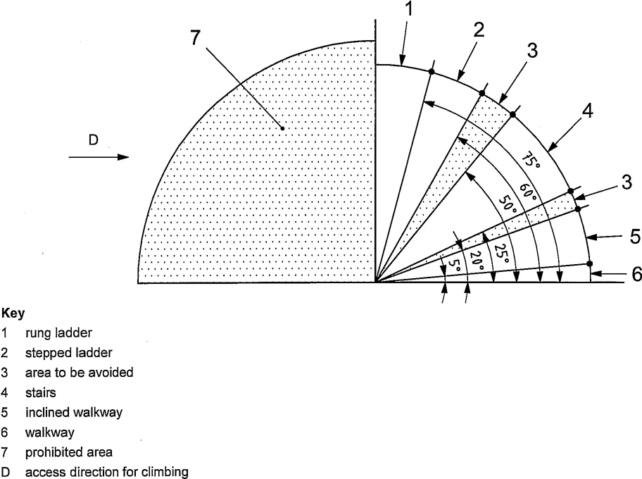
Figure 1 — Ranges of angle for different means of access in their working position
| Equipment | Type 1 | Type 2 | ||
|---|---|---|---|---|
| Collective protective equipment | Personal protective equipment | Collective protective equipment | Personal protective equipment | |
| Stairs | YES (Side protection) |
NO | YES | YES |
| Stepped ladders | YES (Side protection) |
NO | YES (Side protection) |
NO |
| Rungs ladders (foot hold) | YES (Hoop guards) |
NO | YES (Hoop guards) |
YES |
| Walkway | YES (Side protection) |
NO | YES (Side protection) |
YES |
5.1 Provisions shall be made on every access to provide simultaneous three point support (two hands and one foot; or two feet and one hand).
5.2 Where lateral body movement is necessary from a rung of a ladder to another support surface, the distance between the step or rung and the nearest edge of the support surface shall be within a spherical radius of 0.3 m maximum (see Figure 2).
5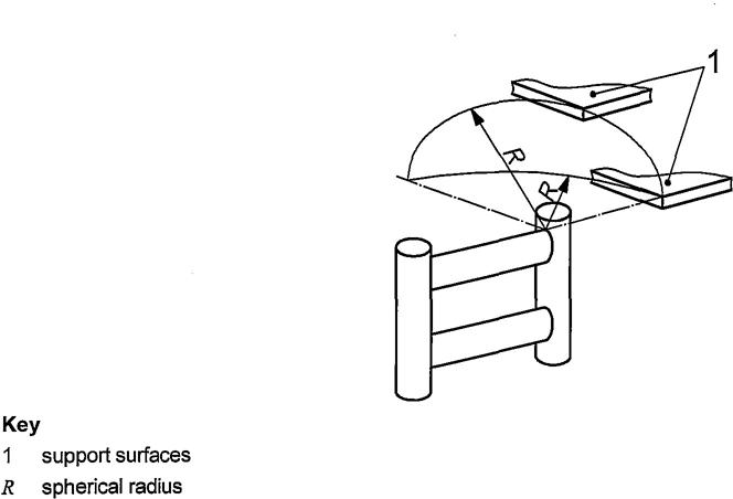
Figure 2 — Distance between a step or rung and the nearest edge of any support surface
5.3 Means of access, walking and standing areas shall:
5.4 Every control station shall have at least one exit onto a fixed means of access. An alternative means of egress shall be provided when the fixed means of access cannot be reached from all working positions of the control station or of the crane.
5.5 Any aperture in the floor of a gangway, inclined walkway, landing or platform situated above an area where persons could be present shall have slots or interstices which:
5.6 Hand supports shall have smooth surfaces. Edges shall have radii (minimum 2 mm) or be chamfered (minimum 2 mm ×2 mm).
Rung ends to retain the hands or feet shall be provided at the ends of handholds and footholds.
5.7 When access is foreseen with portable ladders, permanent means shall be provided to prevent the head of the ladder from moving.
Those ladders shall meet the requirements of this part of ISO 11660 for ladders.
5.8 Where means of access are provided between moving parts of the crane structure, the trapping, crushing, falling hazards shall be addressed in the following preferable order: interlocking, locking, information/marking.
66.1 The steps shall be of the non skid type and the outer edge (nose) shall be free from sharp edges.
6.2 Step construction shall minimize accumulation of debris and aid in the cleaning of mud and debris from the shoe sole where appropriate.
6.3 The steps shall withstand without permanent deformation:
6.4 Type 1 stairs shall be provided with a handrail and an intermediate guard-rail (see Clause 10 and Table 7) on both sides.
If the distance between stairs and a continuous surface is less than 0.2 m it is permissible to omit intermediate guard-rails.
All stepped ladders shall be provided with handrails or handholds on both sides (see Clause 10).
Steps shall be regularly, spaced. The distance from the floor to the first step should be the same as the riser height of the stair or ladder, but may vary to accommodate movement between the floor and the step of for the fitting of standardized components.
Stairs and stepped ladders shall have dimensions in accordance with Figure 3, Table 2 and Table 3.
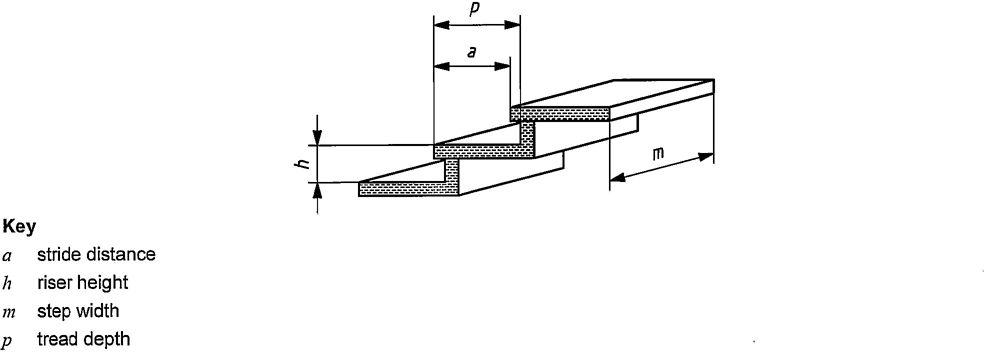
Figure 3 — Dimensional parameters for stairs and stepped ladders
7| Dimensions in metres | ||||
|---|---|---|---|---|
| Parametera | Type 1 access | Type 2 access | ||
| min. | max. | min. | max. | |
| Step width, m | 0,45 | — | 0.32 | — |
| Riser height, hb | 0,18 | 0,25 | 0,18 | 0,25 |
| Tread depth, p | 0,24 | — | 0,2 | — |
| Stride distance, ab, c | 0,15 | 0,27 | 0,15 | 0,27 |
| Height between floor and step | — | 0,6 | — | 0,7 |
| a See Figure 3. | ||||
| b The following formula shall apply:0,6 m< (2h + a) < 0,66 m. The recommended value is (2h + a) = 0,63 m. | ||||
| c Stride distance is also called a going. | ||||
| Dimensions in metres | ||||
|---|---|---|---|---|
| Parametera | Type 1 access | Type 2 access | ||
| min. | max. | min. | max. | |
| Step width, m | 0,45 | — | 0.32 | — |
| Riser height, hb | 0,23 | 0,3 | 0,23 | 0,3 |
| Stride distance, ab, c | 0,08 | — | 0,08 | — |
| Height between floor and step | — | 0,6 | — | 0,7 |
| a See Figure 3. | ||||
| b The formula specified in Table 2 between h and a for stairs is not valid for stepped ladders. | ||||
| c Stride distance is also called a going. | ||||
7.1 Rung ladders
7.1.1 The uprights shall permit a firm grasp and shall be free from sharp edges.
7.1.2 The rungs shall support at their centre a force of 1 200 N distributed over 0,1 m without permanent deformation.
7.1.3 Emergency ladders shall comply with requirements of 7.1.1 and 7.1.2.
7.1.4 The following requirements apply to rung ladders or rungs fixed to a surface:
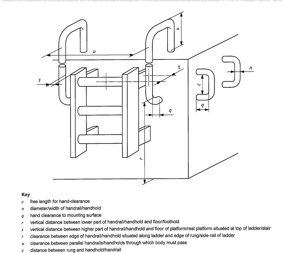
Figure 4 — Dimensional parameters for handholds and handrails
7.1.5 Where a vertical ladder provides access to a walkway, platform or rest platform, handholds need not be provided if one of the following conditions is fulfiled:
Type 1 ladders which present a risk of falling greater than 5 m shall be equipped with a hoop guard (see Clause 8).
Type 1 ladders shall have rest platforms at least every 6 m.
9Flights of ladders shall be positioned or other means provided to prevent persons falling more than 6 m. Whenever possible, flights of ladders shall be positively separated from one another.
The cross-section of a rung shall be circular, or have rounded corners.
The dimensions of rungs and rung ladders shall be in accordance with Figure 5, Figure 6 and Table 4.
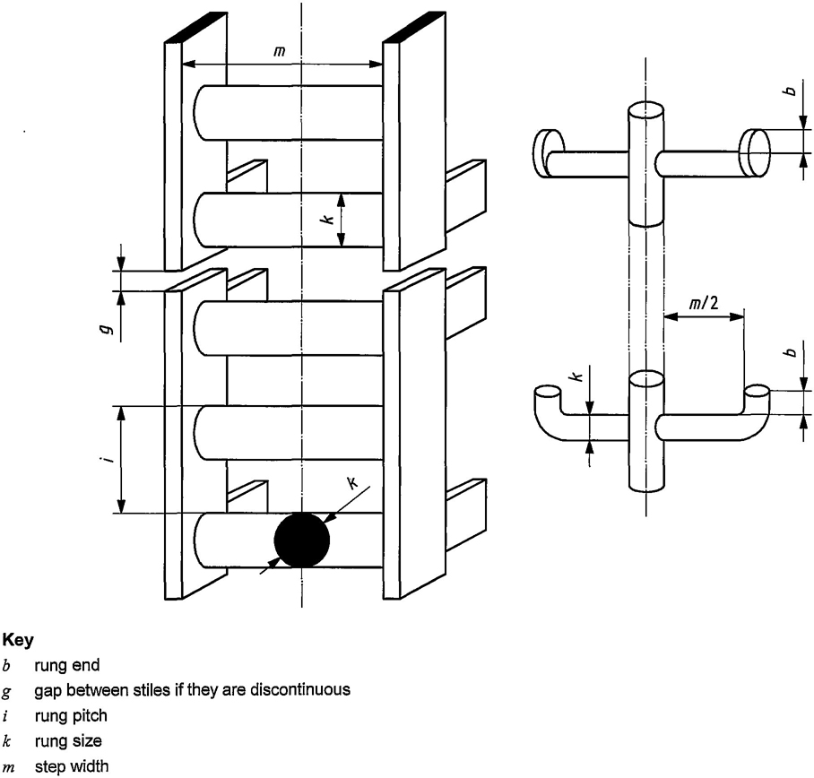
Figure 5 — Dimensions parameters for rung ladder
10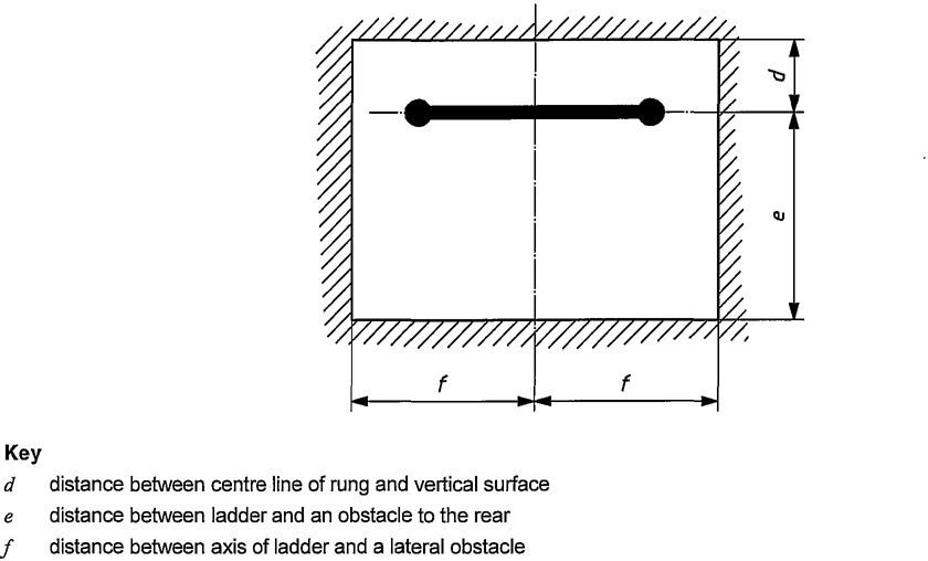
Figure 6 — Free space around the rung (ladder without hoop-guard)
| Dimensions in metres | ||||
|---|---|---|---|---|
| Parametera | Type 1 access | Type 2 access | ||
| min. | max. | min. | max. | |
| Rung pitch, i | 0,23 | 0,30 | 0,23 | 0,30 |
| Height between floor and rung | — | 0,6 | — | 0,7 |
| Distance between centre line of rung and vertical surface, d | 0,15 | — | 0,15b | — |
| Rung size, kc | 0,016 | 0,040 | 0,016 | 0,040 |
| Rung end, b | 0,02 | — | — | — |
| Step width, m | 0,30 | — | 0,30d | — |
| Gap between stiles if they are discontinuous, g | g ≤ 0,01 or g ≥ 0,05e | g ≤ 0,01 or g ≥ 0,05e | ||
| Distance between axis of ladder and a lateral obstacle, f | 0,30 | — | 0,25 | — |
| Distance between ladder and an obstacle to the rear, e | 0,7 | — | 0,7 | — |
| a See Figures 5 and 6. | ||||
| b Distance may be reduced to 0,1 m with discontinuous obstacles. | ||||
| c Diameter for circular cross-section or diameter of inscribed circle for regular shape section with more than three corners, or width of upper flat surface for other profiles. | ||||
| d For placing only one foot, see Figure 5. | ||||
| e Gap of between 0,01 m and 0,05 m is prohibited. | ||||
7.2 Footholds
Depending on the shape of the footholds, their dimensions are similar to the rungs of the ladders or are as given in Figure 7; the values of m and d are given in Table 4 and the values of u and z are given in Table 7.
Handholds (see Clause 10) shall be provided to given access to or from the foothold (see Figure 7 and Table 7).
Footholds shall be regularly spaced. The distance between the floor and the first foothold shall be the same as the riser height with the exception of the first foothold, which may vary to accommodate for movement between the floor and the rung or for the fitting of standardized components.
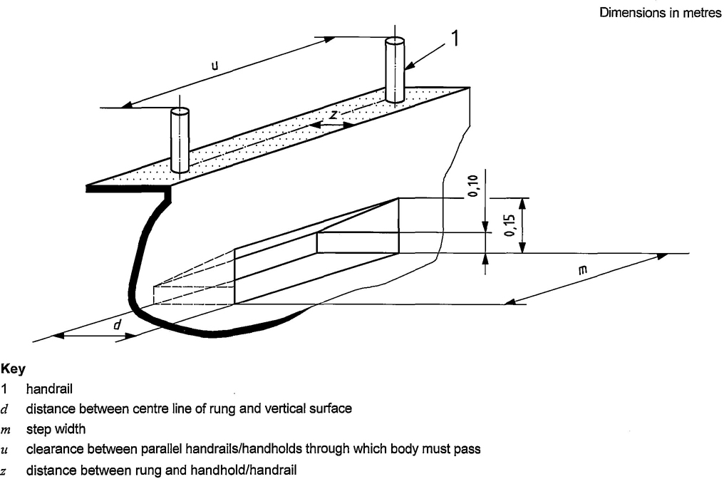
Figure 7 — Dimensions for foothold
128.1 A hoop-guard is required for ladders where there is a risk of falling further than 5m, except when the ladder is located inside a structure such that the structural members provide equivalent protection. This equivalent protection is achieved when the two following conditions are fulfilled:
Hoop-guards dimensions shall be in accordance with Table 5.
The hoops shall be connected by three or five longitudinal bars spaced equally around the hoop. In all cases, a bar shall be fixed in a position diametrically opposite to the centre line of the ladder.
The strength of the hoop guard supported by the longitudinal bars shall allow application at any point on a hoop of a vertical force of 1 000 N distributed over 0,1 m; no permanent deformation shall result.
Where a platform (measured perpendicular to the ladder) has a width of less than or equal to 1m, the gap between the lowest hoop and the handrail shall be reduced to prevent a person from falling through.
NOTE This can be achieved by connecting the hoop to the handrail or equivalent protection (see Figure 9).
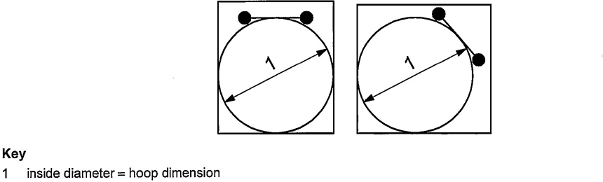
Figure 8 — Free space inside structure
13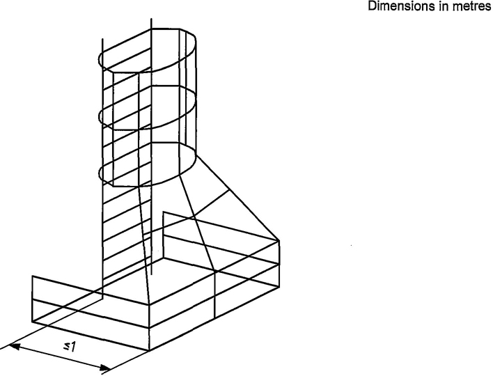
Figure 9 — Example of additional protection
8.2 Movable hoop-guards may be used in conjunction with movable cabin or platform.
8.3 Movable hoop-guards for rung ladders shall:
8.4 Each flexible strap shall:
Movable hoop-guards dimensions shall be in accordance with Table 5.
14| Dimensions in metres | ||||
|---|---|---|---|---|
| Parameter | Type 1 access | Type 2 access | ||
| min. | max. | |||
| Vertical distance between the floor and the first hoop | 2,2 | 2.5 | If hoop-guards are provided, same dimensions as type 1 access. | |
| Inside diameter of the hoop | 0,7 | 0,8 | ||
| Hoop pitch | with 3 vertical bars | — | 0,9 | |
| with 5 vertical bars | — | 1,5 | ||
| Movable hoop guard only | ||||
| Inside diameter of the hoop | 0,6 | 0,65 | ||
| Hoop pitch | — | 0,8 | ||
All surfaces upon which personnel may stand shall withstand, without permanent deformation:
If the dimensions of platform hatch on manhole do not allow space for more than one person, it shall be designed for a minimum force of 1 250 N, instead of the requirements of a) and b) above.
Handholds or handrails shall be provided for walkways, inclined walkways, rest platforms and platforms above 1m. Side protection shall be provided if the vertical drop from the open side of the surface is greater than 3m (see Clause 10).
When a walkway is provided alongside a continuous surface which is intended to provide support in the event of a fall, then a handrail is not required along the continuous surface provided that (see Figure 10):
— H + W ≥ 1,25m, or
— H ≥ 0,7m.
For the choice of dimension of type 2 platforms, items a) to d) listed in 4.2.1 shall be taken into account and the relationship between free height and minimum length of any side shall be in accordance with Figure 11. See also Clause 11.
For the choice of dimension of type 2 walkways and inclined walkways, items a) to d) listed in 4.2.1 shall be taken into account and the relationship between free height and width shall be in accordance with Figure 11. See also Clause 11.
The dimensions of walkways, inclined walkways, platforms, and manholes shall be in accordance with Table 6.
15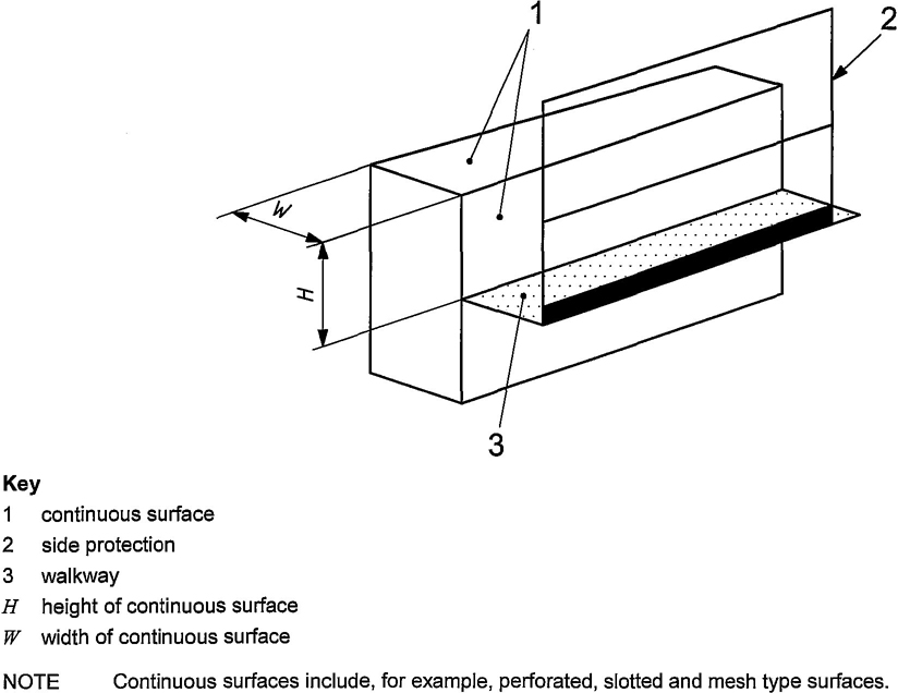
Figure 10 — Walkway provided along a continuous surface
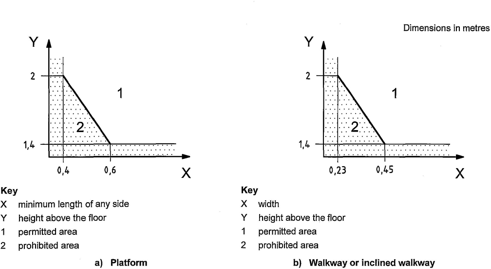
Figure 11 — Relationship between height and other dimensions
16| Dimensions in metres | |||||
|---|---|---|---|---|---|
| Parameter | Type 1 access | Type 2 access | |||
| min. | max. | min. | max. | ||
| Width of walkways/inclined walkways | 0.45a | — | 0.23 | — | |
| Free length × width of rest platforms | 0,4 × 0,4 | — | — | — | |
| Free length × width of platforms | 0,6 × 0,6 | — | 0,4 × 0,4 | — | |
| Free height above floor of walkways/inclined walkways | person moving upright | 2b | — | 1,4c | — |
| person in kneeling posture | — | — | 0,9c | — | |
| Free height above floor of platforms | 2b | — | 1,4c | — | |
| Manhole effective aperture | side of square section/diameter of round section | 0,60 | — | 0,60 | — |
| rectangular section (height × width) | 0,50 × 0,65 | — | 0,50 × 0,65 | — | |
| length of passage through manhole | — | 0,5 | — | 0,5 | |
| NOTE See also Clause 11. | |||||
| a The width of the walkway may be reduced locally to 0,4 m to take account of fixed obstruction with in the access ways. b In the case of a fixed obstacle of 1 m maximum length, this distance may be reduced to 1,4 m: in this case, the obstacle shall be conspicuously marked. c For areas from which maintenance shall be carried out, the corresponding values of type 1 are applicable. |
|||||
Handholds shall be oriented in a manner consistent with the movement.
Handrails and the line of any handholds shall be parallel to the path of motion of the user.
Side protection shall be achieved with a handrail, an intermediate guard-rail and toe board, or any other means of ensuring at least equivalent protection.
Where side protection on a walkway, inclined walkway or rest platform is interrupted for access to a connected stair or ladder, the access space need not be protected.
Where side protection on a platform is interrupted to provide access and there is a risk of falling, the interruption shall be protected by the provision of a self-closing device which cannot open outwards, e.g. a gate.
The use of flexible elements such as chains and ropes is not permitted for side protection.
The dimensions of handholds, handrails, intermediate guard-rails and side protection shall be in accordance with Figures 4,7 and 12 and Table 7.
NOTE See also Clause 11.
The preferred cross-section of a handrail or handhold is circular. A square or rectangular cross-section with rounded corners is permissible.
17The minimum free space for walkways and inclined walkways shall be determined taking into account:
— Figure 11, which shows the relationship between height and other dimensions;
— the free height above the floor of walkways and inclined walkways, as defined in Table 6;
— clearance between parallel handrails through which the body shall pass (dimension u in Figures 4 and 7 and as defined in Table 7.)
The illustration is given in Figure 13.
Hatches shall be capable of only being opened against gravity. Those in rest platforms and walkways shall also be provided with a means to secure the trapdoor in the open position. Hatches in platforms shall be self-closing, e.g. by gravity.
The force necessary to open a hatch shall not exceed 135 N.
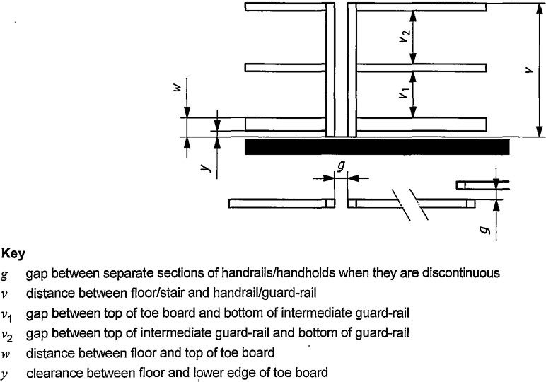
Figure 12 — Dimensional parameters for side protection
18| Dimensions in metres | |||||
| Parametera | Type 1 access | Type 2 access | |||
| min. | max. | min. | max. | ||
| Diameter/width of handrail/handhold, n | 0,016 | 0,043 | 0,016 | 0,043 | |
| Free length for hand-clearance, c | 0,15 | — | 0,15 | — | |
| Distance between rung and handhold/handrail, z | 0 | 0,2 | 0 | 0,2 | |
| Hand clearance to mounting surface, q | 0,075 | — | 0,075 | — | |
| Distance between floor/stair and handrail/guard-rail, v | 1,1 | — | 1,1 | — | |
| Gap between top of toe board and bottom of intermediate guard-rail, v1 | — | 0,5 | — | 0,5 | |
| Gap between top of intermediate guard-rail and bottom of guard-rail, v2 | — | 0,5 | — | 0,5 | |
| Distance between floor and top of toe board, w | for walkway | 0,10 | — | 0,05 | — |
| for platform | 0,10 | ||||
| Clearance between floor and lower edge of toe board, y | — | 0,01 | — | 0,01 | |
| Vertical distance between lower part of handrail/handhold and floor/foothold, y | 1 | 1,6 | 1 | 1,6 | |
| Vertical distance between higher part of handrail/handhold and floor of platform/rest platform situated at top of ladder/stair, s | 1,1 | — | 1,1 | — | |
| Clearance between edge of handrail/handhold situated along ladder and edge of rung/side-rail of ladder, t | 0,075 | 0,2 | 0,075 | 0,2 | |
| Clearance between parallel handrails/handholds through which body must pass, u | 0,45 | — | 0,45b | — | |
| Gap between separate sections of handrails/handholds when they are discontinuous, g | 0,05 | 0,2 | 0,05 | 0,2 | |
| a See Figures 4 and 7. | |||||
| b This dimension shall be observed even for walkways and inclined walkways with smaller width (see Table 6, type 2 access, and Figure 13). In the case of maximum 4m length, this clearance may be reduced to 0,3 m with a minimum height of 2 m. | |||||
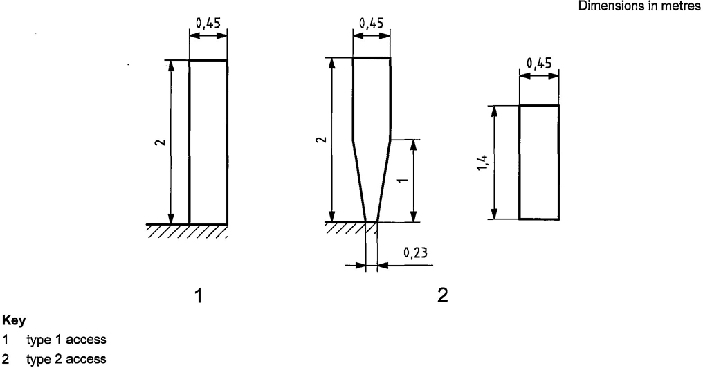
Figure 13 — Minimum free spaces for walkways and inclined walkways
13.1 Guards for moving parts
Moving parts such as drives, projecting axle, ends, wheels, belt-drives, chains, couplings, gearing, rail wheels and pulleys, which might constitute a hazard during normal operation, maintenance or adjustment, shall be guarded. These guards may be removed or taken out of service temporarily if necessary for maintenance or adjustment.
The guards shall support without permanent deformation the weight of a 90 kg person, unless the guard is located in an area where it is forbidden to stand or to circulate during operation or maintenance.
13.2 Prevention of objects from falling
Crane parts such as gears, pulleys, trolley wheels, covers, lids and boxes shall be designed, assembled and fixed in such a way as to prevent them falling during normal operation, when such an event may constitute a hazard.
Covers, guards and access closures shall be fitted with hinges or other means to prevent them from falling.
When hinged, they shall be provided with means such as latches, locks and self weight to maintain them in both the opened and closed positions.
14 Electrical guarding
The electrical guarding shall be in accordance with IEC 60204-32.
20The following are examples of surfaces considered slip-resistant:
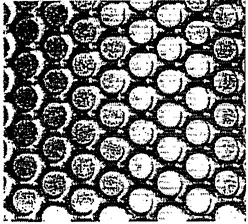
Figure A.1 — Illustration of raised grip surface
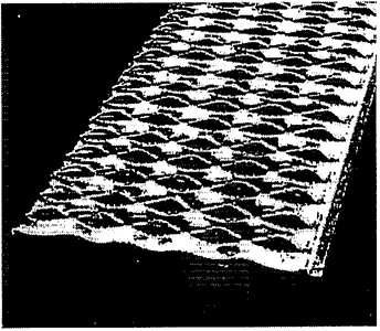
Figure A.2 — Illustration of open grip surface
21ICS 53.020.20
Price based on 22 Pages