
In order to promote public education and public safety, equal justice for all, a better informed citizenry, the rule of law, world trade and world peace, this legal document is hereby made available on a noncommercial basis, as it is the right of all humans to know and speak the laws that govern them.
INTERNATIONAL STANDARD
ISO
11623
First edition
2002–03–01
Bouteilles à gaz transportables — Contrôles et essais périodiques des bouteilles à gaz en matériau composite
Reference number
ISO 11623:2002(E)
© ISO 2002
ii| PDF disclaimer |
| This PDF file may contain embedded typefaces. In accordance with Adobe's licensing policy, this file may be printed or viewed but shall not be edited unless the typefaces which are embedded are licensed to and installed on the computer performing the editing. In downloading this file, parties accept therein the responsibility of not infringing Adobe's licensing policy. The ISO Central Secretariat accepts no liability in this area. Adobe is a trademark of Adobe Systems Incorporated. Details of the software products used to create this PDF file can be found in the General Info relative to the file; the PDF-creation parameters were optimized for printing. Every care has been taken to ensure that the file is suitable for use by ISO member bodies. In the unlikely event that a problem relating to it is found, please inform the Central Secretariat at the address given below. |
© ISO 2002
All rights reserved. Unless otherwise specified, no part of this publication may be reproduced or utilized in any form or by any means, electronic or mechanical, including photocopying and microfilm, without permission in writing from either ISO at the address below or ISO's member body in the country of the requester.
ISO copyright office
Case postale 56 • CH–1211 Geneva 20
Tel. + 41 22 749 01 11
Fax + 41 22 749 09 47
E–mail copyright@iso.ch
Web www.iso.ch
Printed in Switzerland
iiiISO (the International Organization for Standardization) is a worldwide federation of national standards bodies (ISO member bodies). The work of preparing International Standards is normally carried out through ISO technical committees. Each member body interested in a subject for which a technical committee has been established has the right to be represented on that committee. International organizations, governmental and non–governmental, in liaison with ISO, also take part in the work. ISO collaborates closely with the International Electrotechnical Commission (IEC) on all matters of electrotechnical standardization.
International Standards are drafted in accordance with the rules given in the ISO/IEC Directives, Part 3.
The main task of technical committees is to prepare International Standards. Draft International Standards adopted by the technical committees are circulated to the member bodies for voting. Publication as an International Standard requires approval by at least 75 % of the member bodies casting a vote.
Attention is drawn to the possibility that some of the elements of this International Standard may be the subject of patent rights. ISO shall not be held responsible for identifying any or all such patent rights.
ISO 11623 was prepared by the European Committee for Standardization (CEN) in collaboration with Technical Committee ISO/TC 58, Gas cylinders, Subcommittee SC 4, Operational requirements for gas cylinders, in accordance with the Agreement on technical cooperation between ISO and CEN (Vienna Agreement).
Throughout the text of this document, read "…this European Standard…" to mean "…this International Standard…".
Annexes B and ZA form a normative part of this International Standard. Annexes A, C and D are for information only.
Annex ZA provides a list of corresponding International and European Standards for which equivalents are not given in the text.
iv| Page | ||
| Foreword | v | |
| Introduction | 1 | |
| 1 | Scope | 1 |
| 2 | Normative references | 1 |
| 3 | Terms and definitions | 2 |
| 4 | Intervals between periodic inspection and testing | 3 |
| 5 | Procedures for periodic inspection and test | 6 |
| 6 | Identification of cylinder and preparation for inspection and test | 7 |
| 7 | External visual inspection | 7 |
| 8 | Internal visual inspection | 11 |
| 9 | Permeability testing | 12 |
| 10 | Pressure test | 12 |
| 11 | Inspection of value | 12 |
| 12 | Final operations | 13 |
| 13 | Rejection and rendering cylinders unserviceable | 14 |
| Annex A (informative) Example of procedure to be adopted when a cylinder valve is suspected of being obstructed | 24 | |
| Annex B (normative) Damage criteria for wire wound aluminium alloy cylinders | 27 | |
| Annex C (informative) Volumetric expansion testing of gas cylinders | 28 | |
| Annex D (informative) Inspection and maintenance of valves – Recommended procedures | 36 | |
| Annex ZA (normative) Corresponding International and European Standards for which equivalents are not given in the text | 37 | |
This document (EN ISO 11623:2002) has been prepared by Technical Committee CEN/TC 23 "Transportable gas cylinders" the secretariat of which is held by BSI, in collaboration with Technical Committee ISO/TC 58 "Gas cylinders".
This European Standard shall be given the status of a national standard, either by publication of an identical text or by endorsement, at the latest by September 2002, and conflicting national standards shall be withdrawn at the latest by September 2002.
This European Standard has been submitted for reference into the RID and/or in the technical annexes of the ADR. Therefore in this context the standards listed in the normative references and covering basic requirements of the RID/ADR not addressed within the present standard are normative only when the standards themselves are referred to in the RID and/or in the technical annexes of the ADR.
Annexes A, C and D are informative.
Annexes B and ZA are normative.
According to the CEN/CENELEC Internal Regulations, the national standards organizations of the following countries are bound to implement this European Standard: Austria, Belgium, Czech Republic, Denmark, Finland, France, Germany, Greece, Iceland, Ireland, Italy, Luxembourg, Malta, Netherlands, Norway, Portugal, Spain, Sweden, Switzerland and the United Kingdom.
viThe principal aim of periodic inspection and testing is that at the completion of the test the cylinders may be reintroduced into service for a further period of time. It is not possible to identify all considerations for inspecting and re-testing of composite cylinders in this publication. Questions regarding specific cylinders should be directed to the manufacturer.
This standard specifies the requirements for periodic inspection and testing of hoop wrapped and fully wrapped composite transportable gas cylinders, with aluminium, steel or non-metallic liners or of lineless construction, intended for compressed, liquefied or dissolved gases under pressure, of water capacity from 0,5 l up to 450 l.
NOTE As far as practicable, this standard may also be applied to cylinders of less than 0,5 l water capacity.
This standard specifies the requirements for periodic inspection and testing to verify the integrity of such gas cylinders for further service.
This European Standard incorporates by dated or undated reference, provisions from other publications. These normative references are cited at the appropriate places in the text and the publications are listed hereafter. For dated references, subsequent amendments to or revisions of any of these publications apply to this European Standard only when incorporated in it by amendment or revision. For undated references the latest edition of the publication referred to applies (including amendments).
EN 629–2:1996, Transportable gas cylinders – 26E taper thread for connection of valves to gas cylinders — Part 2: Gauge inspection
EN 1089–1, Transportable gas Cylinders — Gas cylinder identification (excluding LPG) — Part 1: Stampmarking
EN 1089–2, Transportable gas cylinders — Gas cylinder Identification (excluding LPG) — Part 2: Precautionary labels
EN 1089–3, Transportable gas cylinders — Gas cylinder identification — Part 3: Colour coding
EN 1795, Transportable gas cylinders (excluding LPG) — Procedures for change of gas service
prEN 1802, Transportable Gas cylinders — Periodic inspection and testing of seamless aluminium alloy gas cylinders
prEN 1968, Transportable gas cylinders — Periodic inspection and testing of seamless steel gas cylinders
prEN 13096, Transportable gas cylinders — Filling conditions for single gases
ISO 32:1977, Gas cylinders for medical use — Marking for identification of content
ISO 6406: 1992, Periodic inspection and testing of seamless steel gas cylinders
ISO 7225:1994, Gas cylinders — Precautionary labels
ISO 10461: 1993, Seamless aluminium-alloy gas cylinders; periodic inspection and testing
ISO 11114-1:1997, Transportable gas cylinders — Compatibility of cylinder and value materials with gas contents — Part 1: Metallic materials
1ISO 11114-2:1997, Transportable gas cylinders — Compatibility of cylinder and value materials with gas contents — Part 2: Non-metallic materials
ISO 11191:1997, Gas cylinders — 25E taper thread for connection of valves to gas cylinders — inspection gauges
ISO 11621: 1997, Gas cylinders — Procedures for change of gas service
ISO 13341:1997, Transportable gas cylinder — Fitting of valves to gas cylinders
ISO 10298, Determination of toxicity of a gas or gas mixture
ISO 13769, Gas cylinders — Stamp marking
For the purpose of this European standard, the following terms and definitions apply.
maximum pressure attained during a burst test
fibres and matrix taken together as a combined unit
layer of material applied to the cylinder as a protective coating or for cosmetic purposes
NOTE Not all composite cylinders will have a special exterior coating.
load-carrying part of the composite overwrap e.g. glass, aramid and carbon
cylinder manufactured only from continuous fibre strands in a resin matrix wrapped in both circumferential and longitudinal directions
steel, aluminium alloy or non-metallic liner wrapped with continous fibre stands in a resin matrix both circumferentially and longitudinally
seamless steel or aluminium alloy liner wrapped with continuous fibre strands or steel wire around only the cylindrical body of the liner, leaving the metal in the neck and base regions exposed. The fibre strands are embedded in a resin matrix
label containing the permanent markings required by the relevant design document and EN 1089-1 or ISO 13769
50 % lethal concentration, as defined in ISO 10298
2service life of the cylinder, if specified on the design drawing
inner portion of the composite cylinder designed both to contain the gas and transmit the gas pressure to the composite overwrap. For hoop wrapped cylinders this provides a substantial structural strength.
liner made from thermoplastic, thermosetting, or elastomer material
removable transparent or non-transparent sleeve fitted to the outside surface of the cylinder
minor refurbishment performed by competent persons under controlled conditions as described in 7.4, e.g. repair of resin matrix
material which is used to bind and hold the fibres in place. It is usually a thermoplastic or thermosetting resin
cylinder not fit for service in its present condition
when LC50 > 200 p.p.m. V/V but ≤ 5 000 p.p.m. V/V, in accordance with ISO 10298
when LC50 ≤ 200 p.p.m. V/V, in accordance with ISO 10298
A cylinder shall fall due for periodic inspection and test on its first receipt by a filler after the expiry of the interval in Tables 1 to 4. However, a shorter period than that in Tables 1 to 4 may be stipulated by the inspection body for the first re-test only.
There is no general requirement for the user to return a gas cylinder before the contents have been used even though the test interval may have lapsed. When the lifetime has expired, the cylinder shall not be refilled and shall be removed from service when presented for the next filling (see clause 13).
In the case of cylinders used for emergency purposes it is the responsibility of the owner or user to submit it for a periodic inspection within the specified interval.
The lists of gases in Tables 1 to 4 are intended as guides only. Reference shall be made to the manufacturer or inspection body if there is a question on the re-test period for specific gases.
3| Description | Gas (c) | Period (Years) |
|---|---|---|
| Compressed gases | e.g. Air, Air, He, H2, Ne, N2, O2, CH4, CO and compressed gas mixtures | 5 or 10 (seeb andd) |
| Liquefied gases | e.g. CO2, N2,O and liquefied gas mixtures | |
| Very toxic gases LC50 ≤ 200 p.p.m. V/V |
e.g. AsH3, PH3 | 3 |
| a Certain requirements may necessitate a shorter time interval e.g. presence of mercury in hydrogen, polymerisation and decomposition reactions. The compatibility of the gas to be filled with aluminium alloys shall be checked in accordance with ISO 11114-1. b For cylinders used for underwater operations and self-contained breathing apparatus, the re-test period shall not exceed five years. c This list of gases is not exhaustive. Gases shall be categorized in accordance with prEN 13096. d The longer test period may apply for cylinders of known designs and safe experience provided approval has been obtained from the competent authority and the manufacturer. |
||
| Description | Gas (g) | Period (Years) |
|---|---|---|
| Compressed gases | e.g. Ar, Xe, Ne, N2, CH4, and compressed gas mixtures H2 Air, O2 CO |
5 or 10 (seef) 5 or 10 (seea andf) 5 or 10 (seeb andf) 2,5 or 5 (seed) |
| Underwater breathing apparatus | Air, O2 | 2,5 (visual) and 5 (full) |
| Liquefied gases | e.g. CO2,N2O and liquefied gas mixtures | 5 or 10 (seec andf) |
| Corrosive gases (to cylinder material) | e.g. Cl2, F2, NO, SO2, HF | 3 |
| Very toxic gases LC50 ≤ 200 p.p.m.V/V | e.g. AsH3, PH3 | 3 |
| Gas mixtures | a) All mixtures except below b) Mixtures containing very toxic gases |
a) Shortest period of any component b) if the toxicity of the final mixture is such that LC50 > 200 p.p.m.V/V, a 5 or 10 year period shall apply (see Note 6). If the toxicity of the final mixture is such that LC50 ≤ 200 p.p.m.V/V, a three year period shall apply. |
| a Certain requirements may necessitate a shorter time interval e.g. the dew point of the gas, polymerisation reactions and decomposition reactions, cylinder design specifications, change of gas service etc. The compatibility of steel with the gas to be filled shall be checked in accordance with ISO 11114-1. b For cylinders used for self-contained breathing apparatus, the re-test period shall not exceed five years. c The longer test period may be used provided the dryness of the product and that of the filled cylinder are such that there is no free water. This condition shall be proven and documented within the quality system of the filler. If the conditions above cannot be fulfilled the cylinder shall be visually and internally inspected every five years and fully re-tested every 10 years. d The longer test period may be used provided the dryness of the product and that of the filled cylinder are such that there is no free water. This condition shall be proven and documented within the quality system of the filler. If the conditions above cannot be fulfilled the cylinder shall be visually and internally inspected every 2,5 years and fully re-tested every five years. e Particular attention shall be paid to the tensile strength and surface condition of such cylinders. Cylinders not conforming to the special hydrogen requirements specified in ISO 11114-1 shall be withdrawn from hydrogen service. Procedures for change of gas service shall be in accordance with EN 1795 or ISO 11621. f The longer test period can apply for cylinders of known designs and safe experience provided approval has been obtained from the competent authority and the manufacturer. g This list of gases is not exhaustive. Gases shall be categorized in accordance with prEN 13096. |
||
| Description | Gas (d) | Period (Years) |
|---|---|---|
| Compressed gases | e.g. Air, Ar, He, H2, Ne, N2O2, CH4, CO and compressed gas mixtures | 5 or 10 (See b and e) |
| Liquefied gases | e.g. CO2, N2O and liquefied gas mixtures | |
| Very toxic gases LC50 ≤ 200 p.p.m. V/V3 | e.g. ASH3, PH3 | 3 (See c and e) |
| a Certain requirements may necessitate a shorter time interval e.g. presence of mercury in hydrogen, polymerisation and decomposition reactions. The compatibility of the gas to be filled with non-metallic liners shall be checked in accordance with ISO 11114-2. b For cylinders used for underwater operations and self-contained breathing apparatus, the re-test period shall not exceed five years. c For mixtures involving these gases, if the toxicity of the final product LC50> 200 p.p.m V/V, a 5 or 10 years period shall apply (seee). d This list of gases is not exhaustive, Gases shall be categorized in accordance with prEN 13096. e The longer test period may apply for cylinders of known designs and safe experience provided approval has been obtained from the competent authority and the manufacturer. |
||
| Description (e) | Gas (c) | Period (Years) |
|---|---|---|
| Compressed gases | e.g. Air, Ar, He, H2, Ne, N2, O2, CH4, Co and compressed gas mixtures | 5 or 10 (Seeb andd) |
| Liquefied gases | e.g. CO2, N2O and liquefied gas mixtures | |
| a Certain requirements may necessitate a shorter time interval e.g. presence of mercury in hydrogen, polymerisation and decomposition reactions. The compatibility of the gas to be filled with non-metallic materials shall be checked in accordance with ISO 11114-2. b For cylinders used for underwater operations and self-contained breathing apparatus, the re-test period shall not exceed five years. c This list of gases is not exhaustive, Gases, shall be categorized in accordance with prEN 13096. d The longer test period may apply for cylinders of known designs and safe experience provided approval has been obtained from the competent authority and the manufacturer. e Very toxic gases shall not be filled into this type of cylinder. |
||
The inspection, testing and repair of composite cylinders shall be carried out only by persons competent in the subject to ensure that the cylinders are fit for continued safe use.
Each cylinder shall be submitted to periodic inspection and test. The following procedures form the requirement for such inspection and test and are explained more fully in later clauses:
– Identification of cylinder and preparation for inspection and test – (see clause 6);
– External visual Inspection – (see clause 7);
– Internal visual inspection – (see clause 8);
– Supplementary tests – (see clause 9);
– Pressure test – (see clause 10);
6– Inspection of valve s– (see clause 11);
– Final operations – (see clause 12);
– Rejection and rendering cylinders unserviceable – (see clause 13).
The internal visual examination (see clause 8) shall be carried out before the pressure test (see clause 10). It is recommended that the other tests are performed in the sequence listed above.
Cylinders which fail the inspection or testing shall be rejected (see clause 13). Where a cylinder passes the above listed procedures but when the condition of the cylinder remains in doubt, additional testing shall be performed to confirm its suitability for continued service or the cylinder shall be rendered unserviceable. Depending on the reason for the rejection cylinders may be recovered and/or repaired (see 7.4).
When cylinders are refurbished during periodic inspection it may be necessary to expose them to heat, for example during initial cleaning, or as part of a stoving operation when painting or powder coating the cylinder. This heat exposure may affect the mechanical properties of the liners and/or the finished composite cylinder.
Therefore the maximum temperature to which these cylinders are exposed shall be controlled and shall not exceed 70° C for a period of 24 h, unless otherwise recommended by the cylinder manufacturer. In such cases the alternative limits shall be clearly indicated on the cylinder or otherwise.
Before any work is carried out the relevant cylinder data (e.g. see EN 1089-1 or ISO 13769) and the gas contents (e.g. see EN 1089-2 or ISO 7225) shall be identified. The cylinder shall be depressurised and emptied in a safe controlled manner before proceeding. A method of dealing with cylinders with inoperative or blocked valves is outlined in annex A. The valve may then be removed.
Cylinders with unknown gas contents or those which cannot be safely emptied of gas shall be set aside for special handling.
The composite material and other integral parts of the composite cylinder shall not be removed prior to inspection. Where a transparent protective sleeve is used it may be left in place as long as the composite wrapping can be inspected effectively without removal. Where a non-transparent protective sleeve is used it shall be removed and only refitted after the pressure test.
Each cylinder shall be cleaned and have all loose paint, coatings, tar, oil or other foreign matter removed from its external surface by a suitable method (e.g. washing, brushing, controlled water jet cleaning, plastic beard blasting). Grit and shot blasting are not suitable. Chemical cleaning agents, paint strippers and solvents which are harmful to the composite cylinder or its materials shall not be used.
Composite cylinders also differ from their metal counterparts in that they may be repaired by a competent person where only limited damages has taken place (see 7.4.) These limits are defined in Table 5 and following repair cylinders shall always be subjected to a pressure test before being returned to service.
The acceptance/rejection criteria given in Table 5 shall be followed, as a minimum. The inspection body shall contact the cylinder manufacturer to establish whether there are more stringent rejection criteria for the particular cylinder design. In case of doubt the inspection body shall make reference to the design drawing of the prototype. In the case where composite cylinders have been designed and manufactured for a limited lifetime, this is indicated on the cylinder marking. Therefore, the marking shall first be checked to ensure that such cylinders are within their lifetime. In the case of hoop wrapped cylinders the exposed external metal surfaces, especially the interface with the overwrapping, shall be inspected in accordance with the respective
7parent periodic inspection and testing standard: i.e. prEN 1968 or ISO 6406 and prEN 1802 or ISO 10461 for steel and aluminum respectively.
The external surface shall be Inspected for damage to the composite. There are three levels of damage that shall be considered of which only two may be repaired (see Table 5).
Damage to the composite overwrap can take a number of forms and examples of these are described in 7.3.2 to 7.3.5. The acceptance/rejection criteria are specified in Table 5, which refers to defined damage levels and the types of damage described in 7.3.2 to 7.3.5. Great care shall be taken to establish the total extent of damage from impact (see 7.3.4) and delamination (see 7.3.5) as surface appearance may not indicate the full extent of the damage. General damage to the cylinder is described in 7.3.6 to 7.3.11.
Annex B specifies additional damage criteria for steel wire wound aluminium alloy cylinders.
Abrasion damage is caused by wearing, grinding or rubbing away by friction. Minor abrasion damage to the protective coating or paint is shown in Figures 1a) and 1b). "Flat spots" evident on the surface could indicate excessive loss of composite overwrap thickness (see Figure 1c)).
Cuts or gouges are caused by contact with sharp objects in such a way as to cut into the composite overwrap, reducing its thickness at that point.
Impact damage may appear as hairline cracks in the resin, or delamination or cuts of the composite overwrap.
Delamination is a separation of layers of strands, or of the strands themselves, of the composite, overwrap. It may also appear as a whitish patch, like a blister or an air space beneath the surface.
Heat or fire damage may be evident by discolouration, charring or burning of the composite overwrap, labels, paint or non-metallic components of the valve.
Where the composite overwrap is only soiled from smoke or other debris and is found to be intact underneath (e.g. no burning of the resin), the cylinder may be returned to service. Cylinders with damage greater than this shall be rendered unserviceable.
A cylinder shall be rendered unserviceable if there is any evidence of abnormal bulges, distorted valve connections, depressions not originally designed, or if, by visual examination of the cylinder interior, there is evidence of damage involving deformation of the liner.
Chemical attack would appear as the dissolution of the resin matrix surrounding the fibres, the cylinder surface feeling "sticky" when touched. The cylinder shall be rendered unserviceable and the manufacturer be contacted for guidance.
8In case of illegibility of the label the manufacturer of the cylinder may be contacted.
In the event that the manufacturer can accurately identify the cylinder a supplementary identification label shall be affixed to the cylinder by the manufacturer. Otherwise the cylinder shall be rendered unserviceable.
Additional inserts in the composite cylinder neck are only permissible where it can be clearly established that they are part of the design of the prototype. The manufacturer shall be referred to for guidance and in the event that they do not conform to the design of the prototype, the cylinder shall be rendered unserviceable.
Where a collar or neck ring or other permanent attachment has been affixed to the composite cylinder it shall be checked with reference to the design drawing of the prototype. The manufacturer shall be referred to for guidance and in the event that it does not conform to the design drawing, the cylinder shall be rendered unserviceable.
Where there are any signs of the attachments becoming loose, they may be repaired and the manufacturer shall be referred to for guidance.
9| Type of damage | Level of damage | ||
|---|---|---|---|
| Level 1 Acceptable damage |
Level 2 Rejectable damage -requiring additional inspections or repairs |
Level 3 Condemned damage -not repairable |
|
| Abrasion damage or damage from cuts | Damage from abrasion or cuts to the following depths are acceptable: - 5% of composite overwrap thickness for fully wrapped cylinders; - 10% of composite overwrap thickness for hoop wrapped cylinders. |
Damage may be cuts or gouges which are deeper or longer than those of level 1, or may include a group of damaged strands or rovings. This level of damage may be repairable. (Seea. Only damage from abrasion and cuts is permitted to be repaired for defects up to and including: - 15% of composite overwrap thickness for fully wrapped cylinders; - 30% of composite overwrap thickness for hoop wrapped cylinders; provided that in either case the maximum length of the above defect is less than 50% of the external diameter of the cylinder. |
Damage is such that the cylinder is no longer suitable for continued service and shall be rendered unserviceable. |
| Impact damage | Damage from impact which is relatively slight and causes a frosted appearance or hairline cracking in the impact area is acceptable. | ||
| Delamination | Only minor delamination of the exterior coating is acceptable. | Loose fibre ends from the termination of the wrapping process shall be repaired. (Seea). | |
| Other damage | - Minor damage that would be considered normal. Such damage should have no adverse effects on the safety of the cylinder and its continued use. -Damage that has no appreciable depth or small groups of abraded fibres are considered in this category. |
||
| a The damaged area shall be repaired with a resin compatible with the existing matrix (see 7.4) | |||
A resin system may be used to repair composite cylinders. Reference shall be made to the design drawing of the prototype, or the manufacturer for confirmation of the resin system and repair procedure to be used.
10All repaired cylinders shall be subjected to a pressure test before being returned to service. After pressure test the repairs shall be examined for lifting, peeling or determination of the composite overwrap. The damage criteria identified in 7.3 shall be used.
A sequence of photographs illustrating a typical repair procedure is shown in Figures 7a) to 7e).
In the event of a failure, if it can be established that the repair procedure was inadequate or not followed then a second and final repair may be performed. Any cylinder showing signs of delamination after a second pressure test shall be rendered unserviceable.
The whole of the internal surface of each cylinder shall be inspected, using an adequate technique and illumination to identify and defects present. Any cylinder showing presence of foreign matter or signs of more than light surface corrosion shall be cleaned internally under closely controlled conditions by controlled water jet cleaning, flailing, steam jet (see 5.2), rumbling with ceramic ships or other suitable method (grit or shot blasting is considered most suitable for steel liners). Any chemical solutions and/or cleaning methods used shall be selected to ensure that they do not adversely affect the liner or composite overwrap materials. Care shall be taken to avoid damaging the cylinder. After cleaning and drying, the cylinders shall be inspected again and any cylinder showing excessive corrosion, dents or cracks shall be rendered unserviceable.
For steel or aluminium alloy liners, the inspection shall be in accordance with prEN 1968 or ISO 6406, or prEN 1802 or ISO 10461 respectively.
For cylinders without liners or with non-metallic liners the following criteria shall be used:
Any cylinder showing presence of foreign matter or signs of more than light surface corrosion shall be cleaned internally under closely controlled conditions by controlled water jet cleaning or a method recommended by the manufacturer. Any chemical solutions used for cleaning and/or cleaning methods used shall be strictly in accordance with the cylinder manufacturer's procedures.
After cleaning and drying, the cylinders shall be inspected again and any cylinder showing discolouration or other surface defects such as heat damage shall be permeability tested (see clause 9).
The neck threads (valve connections) of the cylinder shall be inspected and gauged to ensure that they are:
– clean and of full form;
– free from burrs or damage;
– free from cracks;
Additional information on neck and shoulder cracks can be found in prEN 1802 or ISO 10461 and prEN 1968 or ISO 6406.
Where necessary and where the manufacturer confirms that the design of the neck permits, threads may be re-tapped to provide the appropriate number of effective threads. After re-tapping the threads shall be checked using the appropriate thread gauge (e.g. EN 629-2 for 25E threads).
11Where there is doubt concerning the type or severity of a defect found on visual inspection additional tests or methods of examination may be applied. The following method for permeability testing is recommended but alternatives are permitted which achieve the same result.
This entire test shall be performed at a temperature of (20 ± 5) °C. The cylinder shall be charged to its working pressure with air or an inert gas and the valve and the junctions of the liner (if present) with the metallic bosses or rings shall be visually checked for leaks (e.g. with soapy water). Any leaks shall be eliminated, where the design permits, before proceeding with this test.
The cylinder is then recharged, if necessary, to its working pressure, weighted and the mass of the stored gas recorded. The accuracy of the weighing scales shall be such as to detect the expected mass change. The cylinder shall be weighted after 24 h (or longer in case of any doubt) and the loss of mass shall be determined.
The rate of loss shall be less than 0,25 ml. hr¯1 per litre of cylinder water capacity. If the leakage rate is greater or equal to 0.25 ml.hr¯1 per litre of cylinder water capacity then the cylinder shall be rejected.
NOTE Adequate safety precautions should be taken to contain any energy which may be released.
Each cylinder shall be submitted to a pressure test using a suitable fluid, normally water, as the test medium. This may be a proof pressure test, or a volumetric expansion test (see annex C), as appropriate to the design of the cylinder. The method used shall not reduce the integrity of the cylinder. The pressure test method used need not to be the same as that used at the times of manufacture unless specified in the design. Having decided to due one particular type of test, its result shall be final. No attempt shall be made to be transfer from one type of test to the other. All types of composite cylinder covered by this standard shall be tested according to prEN 1968 or ISO 6406 or prEN 1802 or ISO 10461 as appropriate. The test pressure shall be established from the marking on the cylinder.
The proof pressure test requires that the pressure in the cylinder is increased gradually until the test pressure is reached. The cylinder test pressure shall be held for at least 30 s to ascertain that there is no tendency for the pressure to decrease and that tightness is guaranteed. Adequate safety precautions shall be taken during the test. Any cylinder failing to conform to with the requirements of this test shall be rendered unserviceable.
Only a proof pressure test shall be used for testing composite cylinders wound with steel wire.
NOTE In the case where a pneumatic pressure test is carried out appropriate measures should be taken to ensure safe operation and to contain any energy which may be released.
If a water jacket is used for a volumetric expansion test air may be expelled from the composite overwrap or water absorbed by the composite overwrap during the pressurisation cycle. The design of the test equipment and/or test procedure may need to be modified to take these factors into account.
The permanent volumetric expansion shall not exceed 5% or such lower figure as required by the competent authority for a specific design.
If a valve is to be reintroduced into service, it shall be inspected to ensure that it will perform satisfactorily and ensure gas tightness. An example of how this may be achieved is given in annex D.
12The interior of each cylinder shall be thoroughly dried by a suitable method immediately after the pressure test, such that there is no trace of free water. The interior of the cylinder shall be inspected to ensure that it is dry and free from other contaminants. Should heat be used care shall be taken to ensure that the maximum temperature and time indicated in 5.2 are not exceeded.
Cylinders are sometimes repainted using paints which require stoving. In these circumstances care shall be taken to ensure that the maximum time and temperature as indicated in 5.2 are not exceeded, so that the cylinder is not degraded in any way. It is recommended that the manufacturer is referred to for appropriate painting procedures for their cylinders. Care shall be taken that the identification label is masked out prior to painting to ensure its continuing legibility.
Before re-valving the cylinder the neck thread shall be inspected in accordance with 8.2.
The valve shall be fitted to the cylinder using a suitable method of sealing. The optimum torque necessary to ensure both the seal between the valve and the cylinder and prevent any possibility of over stressing of the neck shall be used, in accordance with ISO 13341.
The torque applied shall take into consideration the size and form of the threads, the material of the valve and the type of sealing method used, according to the cylinder manufacturer's recommendations. Where the use of lubricants/sealing material is permitted only those compatible with the gas service shall be used, taking particular care for oxygen service, in accordance with ISO 11114-2 and ISO 13341.
The requirements shall only apply to cylinders for liquefied gases and compressed gases filled by weight. The tare of the cylinders shall be obtained by weighing on a machine regularly calibrated and checked for accuracy. The capacity of the weighing machine shall be suitable for the tare weight of the appropriate cylinders.
The tare shall include the mass of the cylinder, valve(s) and all permanent fittings. If the tare of the cylinder differs from the marked tare by more than the value shown in Table 6 and is not to reason of damage, the original tare shall be cancelled and the correct tare marked in a permanent and legible fashion, in accordance with EN 1089-1 or ISO 13769.
| Cylinder water capacity l |
Maximum allowable deviation in tare weight g |
|---|---|
| ≤ 5 | ± 50 |
| > 5 to < 20 | ± 200 |
| ≥ 20 | ± 400 |
After satisfactory completion of the periodic inspection and test each cylinder shall be permanently marked or labelled according to EN 1089-1 or ISO 13769, with:
The next test date shall be shown by an appropriate method such as a disc fitted between the valve and the cylinder, indicating the date (year) of the next periodic inspection test.
Where required by cylinder owner/operator the cylinder contents shall be identified in accordance with EN 1089-2 or ISO 7225 and EN 1089-3 or ISO 32. If painting is required care shall be exercised in accordance with 12.2 of this standard. If a change of gas service is involved, the requirements of EN 1795 or ISO 11621 shall be conformed to.
NOTE Users of this standard should take account of legal requirements on identification which may be applicable in the country of use.
Details of the present test shall be recorded by the test station and the following information shall be available:
– Owner's name;
– Manufacturer's or owner's serial number;
– Cylinder mass or tare where applicable;
– Test pressure;
– Present test date;
– Identification symbol of inspection body or test station;
– Identification of inspector;
– Details of any modifications made to the cylinder by the inspector.
Additionally it shall be possible to obtain the following items of information from records which need not necessarily be kept on a single file but will enable a particular cylinder to be traced. These items are:
– Cylinder manufacturer;
– Manufacturing specification;
– Water capacity/size.
All information regarding the test shall be retained by the test station and shall be made available to the manufacturer for the life of the cylinder.
The decision to reject a cylinder may be taken at any stage during the inspection and test procedure. If it is not possible to recover a rejected cylinder it shall, after notifying the owner, be made unserviceable by the test station for holding gas under pressure so that it cannot be reissued into service.
NOTE In case of any disagreement, ensure that the legal implications of the contemplated action are fully understood.
14One of the following methods shall be employed:
– By crushing the cylinder using mechanical means;
– Cutting the neck off the cylinder;
– Irregular cutting of the cylinder in two or more pieces;
– By hydraulically pressuring the cylinder to failure, although care shall be taken to ensure that this is carried out in a safe manner.
15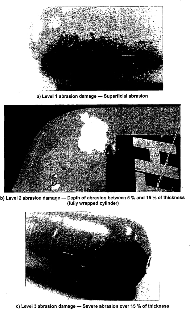
Figure 1 — Abrasion damage
16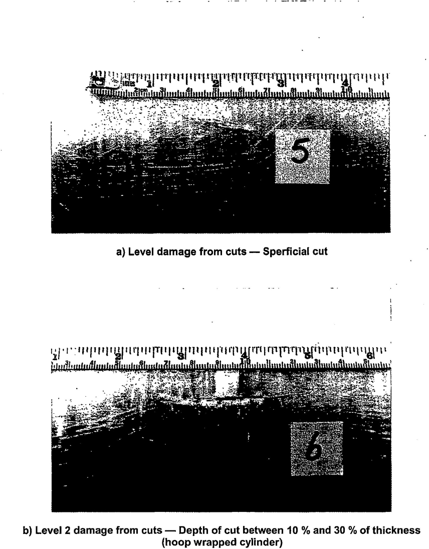
Figure 2 — Damage from cuts
17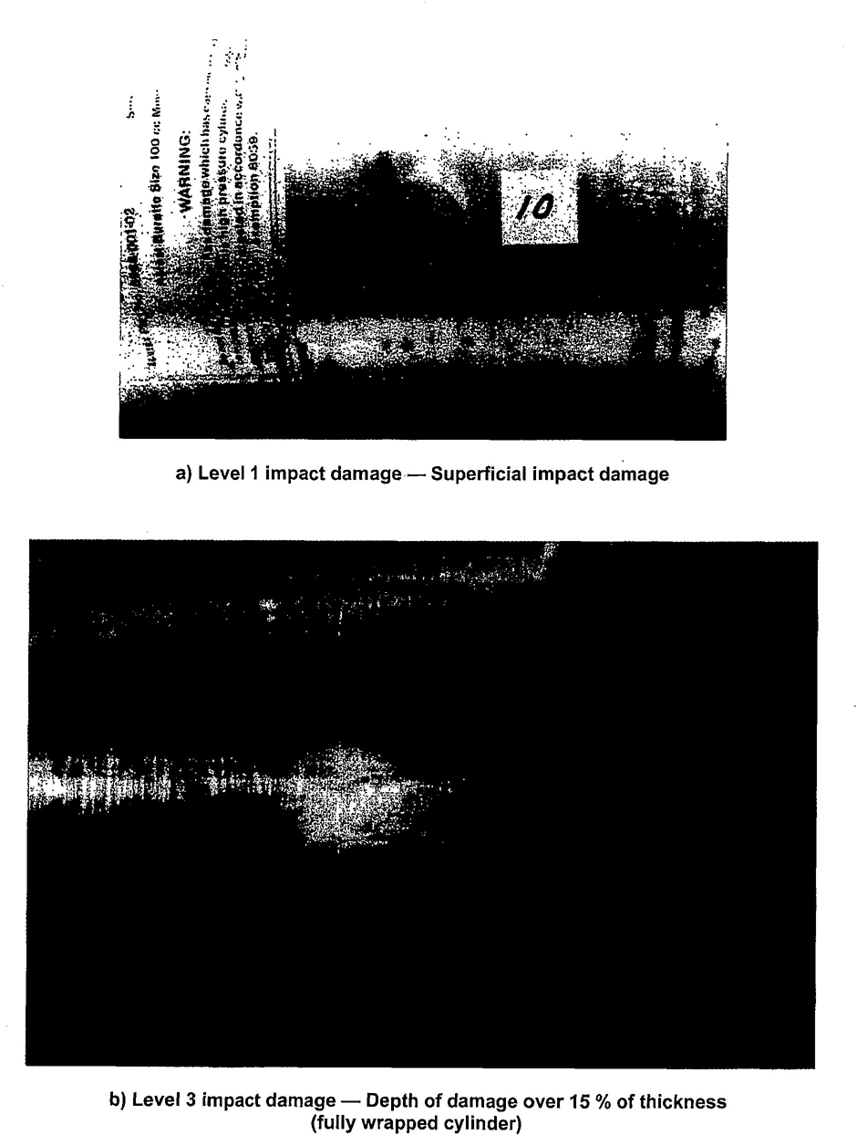
Figure 3 — Impact damage
18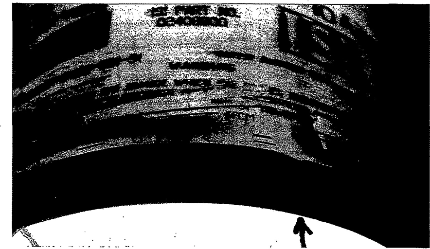
Figure 4 — Delamination
19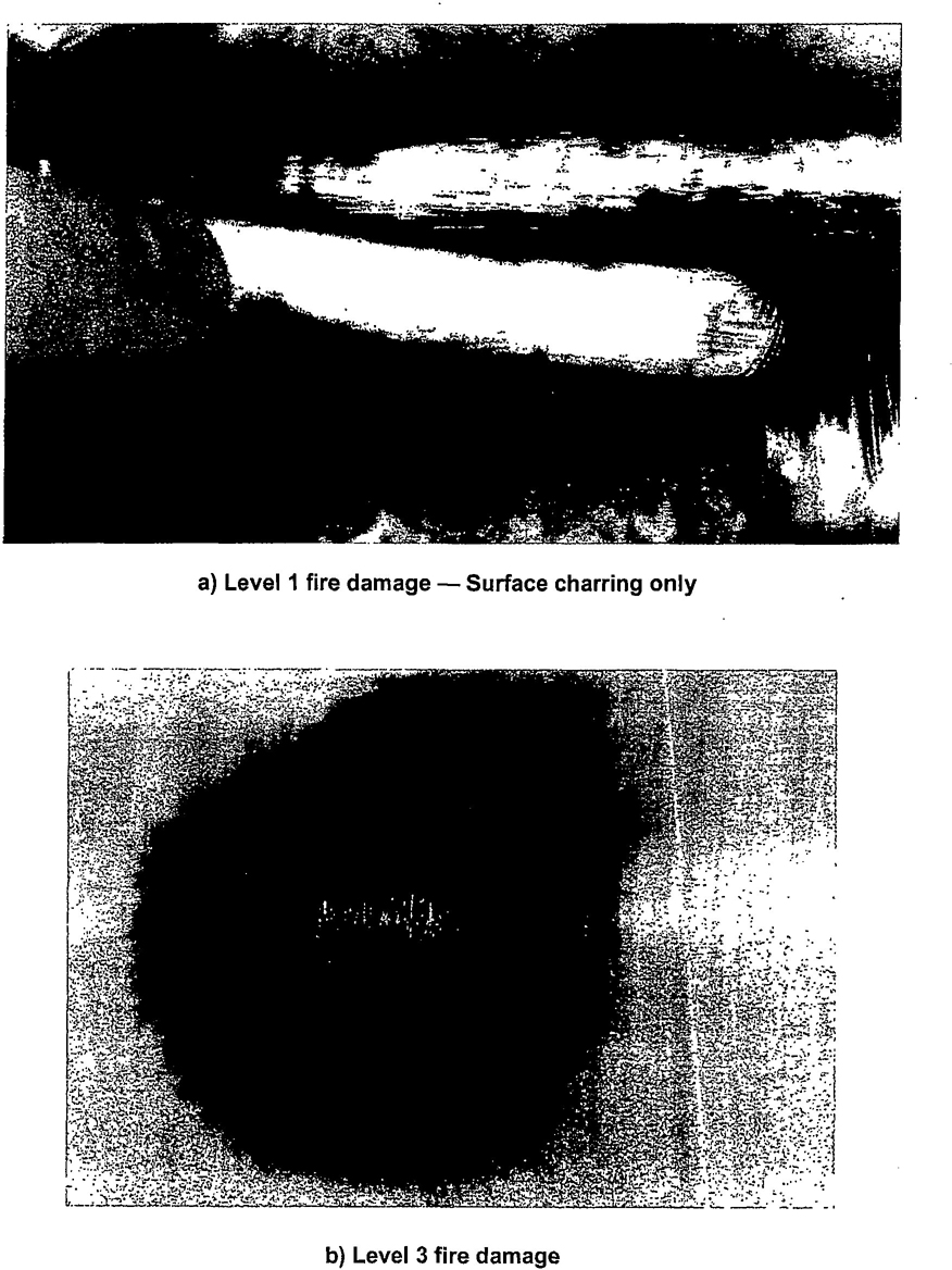
Figure 5 — Heat or fire damage
20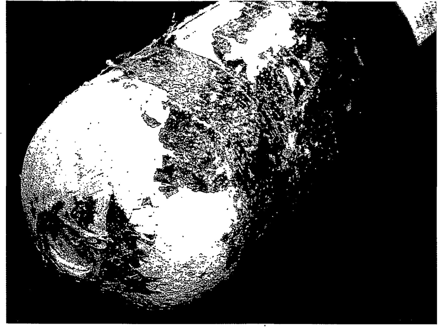
Figure 6 — Chemical attack (24 h in paint stripper)
21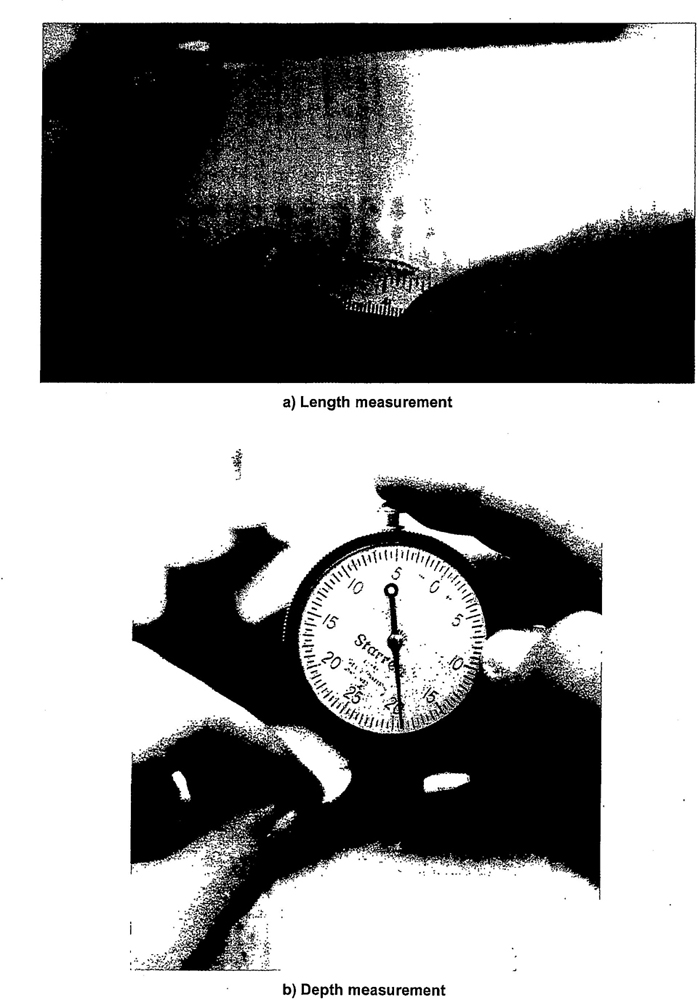
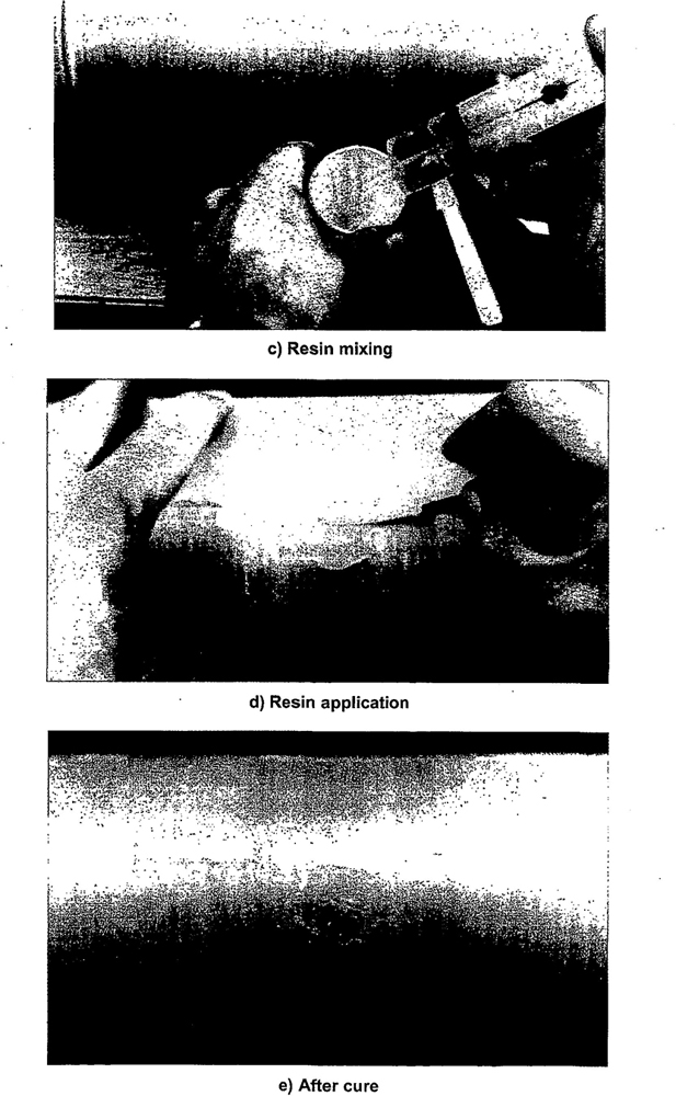
Figure 7 — Typical repair procedure
23The methods suggested herein for dealing with cylinder valves which are suspected of being obstructed have been found to produce satisfactory results. Other acceptable methods may be employed.
If there is any doubt when the valve of a gas cylinder is opened that gas is not being released and the cylinder may still contain residual gas under pressure, a check or checks shall be made to establish that the free passage through the valve is not obstructed.
The method adopted shall be a recognised procedure such as one of the following or one that provides equivalent safeguards:
a) By introducing gas at a pressure up to 5 bar and checking its discharge.
b) By using the device shown in Figure A.1 to hand pump inert gas into the cylinder.
c) For cylinders of liquefied gases, first check to establish that the total weight of the cylinder is the same as the tare stamped on the cylinder. If there is a positive difference, the cylinder may contain either liquefied gas under pressure or contaminants.
When it is established that there is no obstruction to gas flow in the cylinder valve, the valve may be removed.
When a cylinder is found to have an obstructed gas passage in the valve, the cylinder shall be set aside for special attention as follows:
a) By sawing or drilling the valve body until interception is made with the gas passage between the valve body stem and valve spindle seat. This operation shall be properly cooled particularly when handling oxidising gases.
b) By loosening or piercing the safety device in a controlled manner.
These methods are applicable for cylinders of non-toxic, non-flammable gases. Appropriate safety precautions shall be taken to ensure that no hazard results from the uncontrolled discharge of any residual gas.
Where the contents are toxic or flammable, the preferred method is to unscrew partially the valve within a glanded cap, secured and joined to the cylinder and vented to a safe discharge. The principles of a suitable device are illustrated in Figure A.2.
These procedures may be carried out only by trained personnel. When the gas, if any, has been released and the pressure within the cylinder reduced to atmospheric, and, in the case of liquefied gases, there is no frost or dew on the outside of the cylinder, the valve may be removed.
24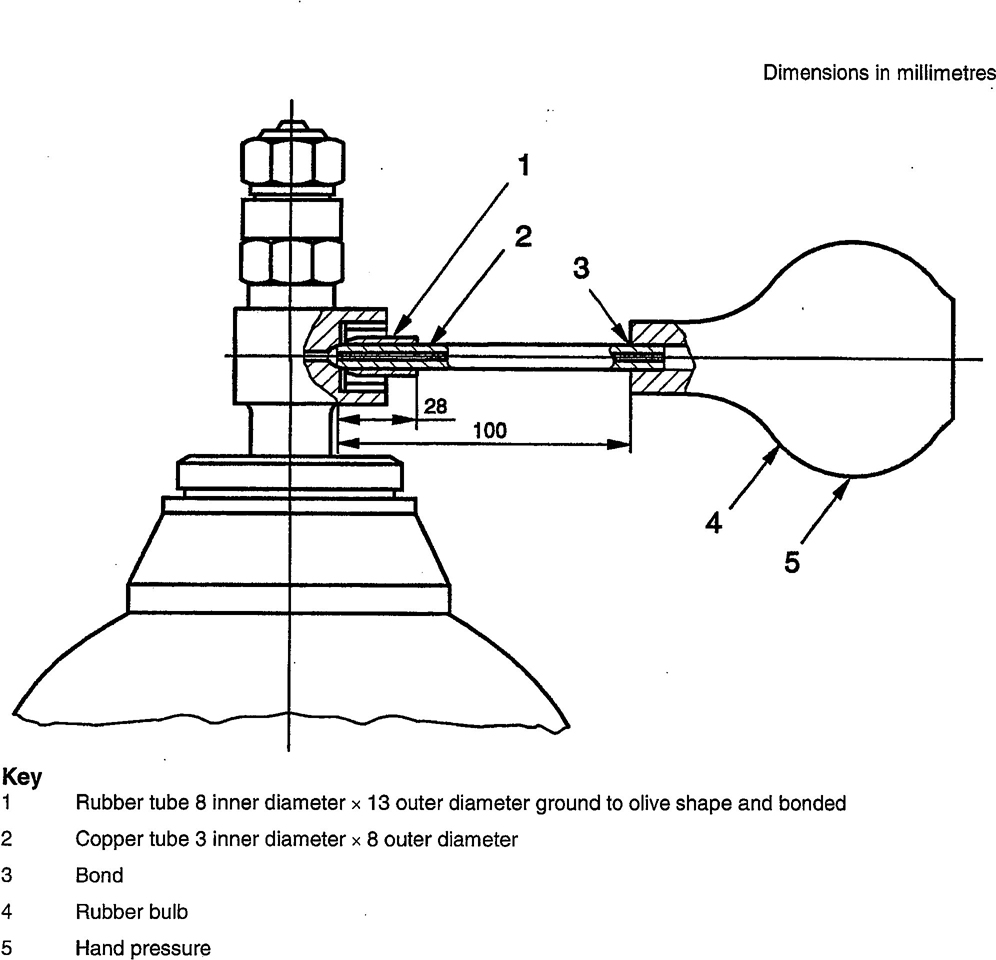
Figure A.1 — Device for detecting obstructed cylinder valve
25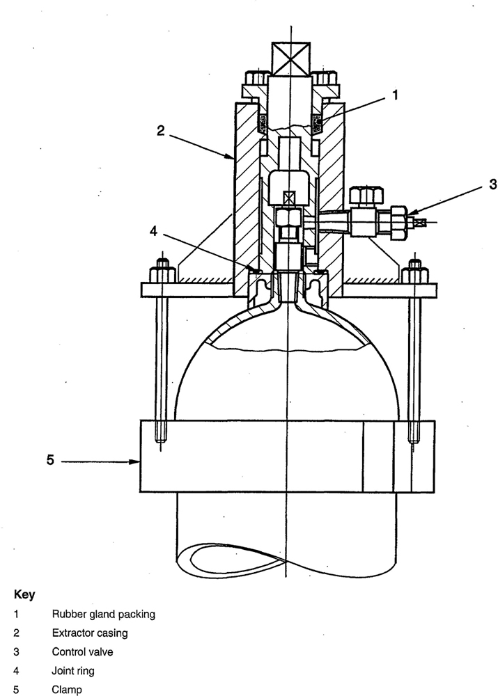
Figure A.2 — Typical device for the removal of a damaged gas container valve
26This annex covers specific damage criteria additional to those described in 7.3.
The steel wire shall not be removed for the purposes of this inspection.
The specific criteria are:
a) Corrosion damage:
Corrosion of the liner may appear as pitting, alumina powder or bulges under the steel wire. Corrosion of the steel wire is characterised by the presence of rust.
Slight corrosion of the steel wire may be repaired by adequate surface preparation followed by its protection (e.g. painting). Heavy corrosion of the steel wire will render the cylinder unserviceable. If any corrosion of the liner underneath the steel wire is observed, the cylinder will be rendered unserviceable.
b) Loosening of steel wire:
The steel wire may lose its tension. In such cases, whereas the individual hoops of the winding were originally in contact with one another, separation will have occurred.
All such types of failure will render the cylinder unserviceable.
c) Failure of aluminium retainers at the ends:
The steel wires are kept in position by aluminium retainers. Mishandling or corrosion may force the retainers to be dislodged. This type of failure can be detected visually. All such types of failure will render the cylinder unserviceable.
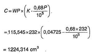
27This annex gives details of the two methods of determining the volumetric expansion of composite gas cylinders.
a) The water jacket method
b) The non–water jacket method
The water jacket method volumetric expansion test may be carried out on equipment with a levelling burette or with a fixed burette or by weighing the mass of water displaced.
The following requirements are general to the methods of test:
a) Hydraulic test pressure pipelines shall be capable of withstanding a pressure twice the maximum test pressure of any cylinder that may be tested.
b) Glass burettes shall be of sufficient length to contain the full volumetric expansion of the cylinder and shall have bore of uniform diameter such that the expansion can be read to an accuracy of 1 % or 0,1 ml, whichever is the greater.
c) Weighing scales shall be to an accuracy of 1 % or 0,1 g whichever is the greater.
d) Pressure gauges shall be of the industrial class with a scale appropriate to the test pressure. They shall be tested at regular intervals in any case but not less frequently than once per month.
e) A suitable device shall be employed to ensure that no cylinder is subjected to a pressure in excess of its test pressure.
f) Pipework should utilise long bends in preference to elbow fittings and pressure pipes should be as short as possible. Flexible tubing should be capable of withstanding twice the maximum test pressure in the equipment and have sufficient wall thickness to prevent kinking.
g) All joints should be leak–tight.
h) When installing equipment, care should be taken to avoid trapping of air in the system.
This method of test necessitates enclosing the water filled cylinder in a jacket also filled with water. The total and any permanent volumetric expansion of the cylinder are measured as the amount of water displaced by the expansion of the cylinder when under pressure and the amount of water displaced after the pressure has been released. The permanent expansion is calculated as a percentage of the total expansion. The water jacket should be fitted with a safety device capable of releasing the energy from any cylinder that may burst at test pressure.
An air bleed valve should be fitted to the highest point of the jacket.
28Two methods of performing this test are described in C.3.2 and C.3.3. Other methods are acceptable provided that they are capable of measuring the total, and, if any, the permanent volumetric expansion of the cylinder.
The equipment should be installed as shown in Figure C.1.
Procedure
a) Fill the cylinder with water and attach it to the water jacket cover;
b) Seal the cylinder in the water jacket and fill the jacket with water, allowing air to bleed off through the air bleed valve;
c) Connect the cylinder to the pressure line. Adjust the burette to zero level by manipulation of the jacket filling valve and drain valve. Raise the pressure to 2/3 of the test pressure, stop pumping and close the hydraulic pressure line valve. Check that the burette reading remains constant;
d) Re–start the pump and open the hydraulic pressure line valve until the cylinder test pressure is reached. Close the hydraulic pressure line valve and stop pumping;
e) Lower the burette until the water level is at the zero mark on the burette support. Take a reading of the water level in the burette. This reading is the total expansion and shall be recorded on the test certificate;
f) Open the hydraulic line drain valve to release the pressure from the cylinder. Raise the burette until the water level is at the zero mark on the burette support. Check that pressure is at zero and that water level is constant;
g) Read the water level in the burette. This reading is the permanent expansion, if any, and shall be recorded on the test certificate;
h) Check that the permanent expansion as determined by the following equation:
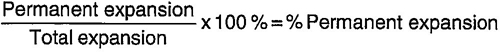
does not exceed the percentage given in the design specification.
The equipment should be installed as shown in Figure C.2.
Procedure:
The procedure for this method of test is similar to that described in C.3.2 except that the burette is fixed:
Follow procedures C.3.2 a) and b);
Connect the cylinder to the pressure line;
Adjust the water level to a datum. Apply pressure until the test pressure is reached and record the burette reading. The reading above the datum is the total expansion, and shall be recorded on the test certificate;
Release the pressure and record the burette reading. The reading above the datum is the permanent expansion and shall be recorded on the test certificate;
Check that the permanent volumetric expansion as determined by the following equation:
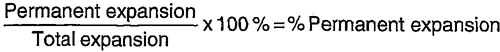
does not exceed the percentage given in the design specification.
29This method consists of measuring the amount of water passed into the cylinder under proof pressure, and on release of this pressure, measuring the water returned to the manometer. It is necessary to allow for the compressibility of water, and the volume of the cylinder under test to obtain true volumetric expansion. No fall in pressure under this test is permitted.
The water used should be clean and free of dissolved air. Any leakage from the system or the presence of free or dissolved air will result in false readings.
The equipment should be installed as shown in Figure C.3. This figure illustrates diagrammatically the different parts of the apparatus. The water supply pipe should be connected to an overhead tank as shown, or to some other supply giving a sufficient head of water.
The apparatus shall be arranged such that all air can be removed and that accurate readings can be determined of the volume of water required to pressurise the filled cylinder and of the volume expelled from the cylinder when depressurised. In the case of larger cylinders, it may be necessary to augment the glass tube with metal tubes arranged in the manifold.
If a single acting hydraulic pump is used, care shall be taken to ensure that the piston is in the back position when the water levels are noted.
a) Completely fill the cylinder with water and determine the weight of water required;
b) Connect the cylinder to the hydraulic test pump through the coil and check that all valves are closed;
c) Fill the pump and system with water from tank 1 by opening valves 8, 9 and 10;
d) To ensure the expulsion of air from the system, close the air–bleed and bypass valves and raise the system pressure to approximately one–third of the test pressure. Open the bleed valve to release the trapped air by reducing the system pressure to zero, and reclose the valve. Repeat if necessary;
e) Continue to fill the system until the level in the glass manometer is approximately 300 mm from the top. Close the make–up valve and mark the water level with a pointer, leaving the isolating and air–bleed valves open. Record the level;
f) Close the air bleed valve. Raise the pressure in the system until the pressure gauge records the required test pressure. Stop the pump and close the hydraulic line valve. After approximately 30 s there should be no change in either the water level or the pressure. A change in level indicates leakage. A fall in pressure, if there is no leakage, indicates that the cylinder is still expanding under pressure;
g) Record the fall in water level in the glass tube. (Provided that there has been no leakage, all the water drained from the glass tube will have been pumped into the cylinder to achieve the test pressure.) The difference in water level is the total volumetric expansion;
h) Open the hydraulic main and bypass valves slowly to release the pressure in the cylinder and allow the water so released to return to the glass tube. The water level should return to the original level marked by the pointer. Any difference in level will denote the amount of permanent volumetric expansion in the cylinder, neglecting the effect of the compressibility of the water at the test pressure. The true permanent volumetric expansion of the cylinder is obtained by correcting for the compressibility of the water which is given by the equation in C.4.5;
i) Before disconnecting the cylinder from the test rig, close the isolating valve. This will leave the pump and system full of water for the next test. Action d) shall, however, be repeated at each subsequent test;
j) If permanent volumetric expansion has occurred, record the temperature of the water in the cylinder.
30a) The tests determine the volume of water required to pressurize the filled cylinder to the test pressure;
b) The total mass and temperature of water in the cylinder are known, enabling the change in volume of the water in the cylinder owing to its compressibility to be calculated. The volume of water expelled from the cylinder when depressurized is known. Thus the total volumetric expansion and the permanent volumetric expansion can be determined;
c) The permanent volumetric expansion shall not exceed the percentage given in the design specification.
The formula used for the calculation of water is as follows:
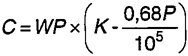
where C is the reduction in volume of water due to its compressibility, in cubic centimetres (cm3)
W is the mass of water in kilogramms (kg)
P is the pressure in bar (bar)
K is the compressibility factor for individual temperature as listed in Table C.1.
| Temperature (°C) |
K | Temperature (°C) |
K | Temperature (°C) |
K |
|---|---|---|---|---|---|
| 6 | 0,049 15 | 13 | 0,047 59 | 20 | 0,046 54 |
| 7 | 0,048 86 | 14 | 0,047 42 | 21 | 0,046 43 |
| 8 | 0,048 60 | 15 | 0,047 25 | 22 | 0,046 33 |
| 9 | 0,048 34 | 16 | 0,047 10 | 23 | 0,046 23 |
| 10 | 0,048 12 | 17 | 0,046 95 | 24 | 0,046 12 |
| 11 | 0,047 92 | 18 | 0,046 80 | 25 | 0,046 04 |
| 12 | 0,047 75 | 19 | 0,046 68 | 26 | 0,045 94 |
In the following example calculation, allowance for pipe stretch has been neglected.
EXAMPLE
Test pressure = 232 bar
Mass of water in cylinder at zero gauge pressure = 113,8 kg
Temperature of water = 15 °C
Water forced into cylinder to raise pressure to 232 bar = 1745 cm3 (or 1,745 kg)
Total mass of water in cylinder at 232 bar = 113,8 kg + 1,745 kg = 115,545 kg
Water expelled from cylinder to depressurise = 1 742 cm3
Permanent expansion = (1 745 – 1742) cm3 = 3 cm3
31From Table C.1 factor for 15 °C = 0,04725
Total volumetric expansion = 1 745 cm3 − 1 224,31 cm3 = 520,686 cm3

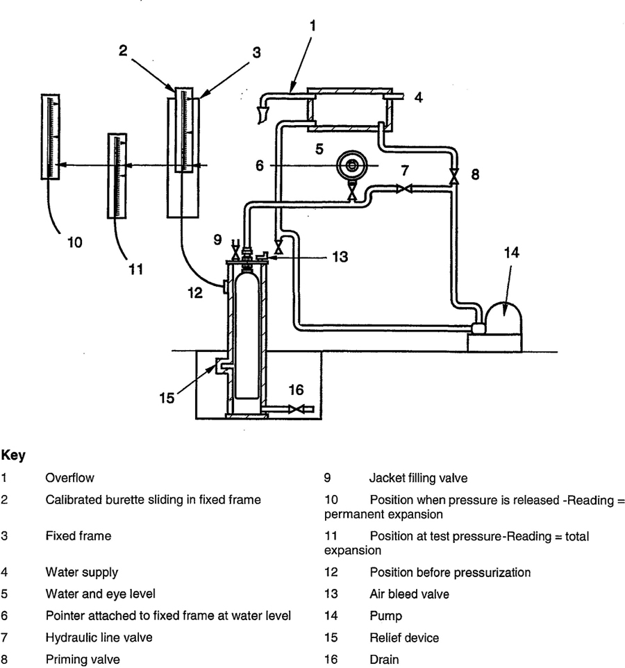
Figure C.1—Water jacket volumetric expansion test (levelling burette method)
33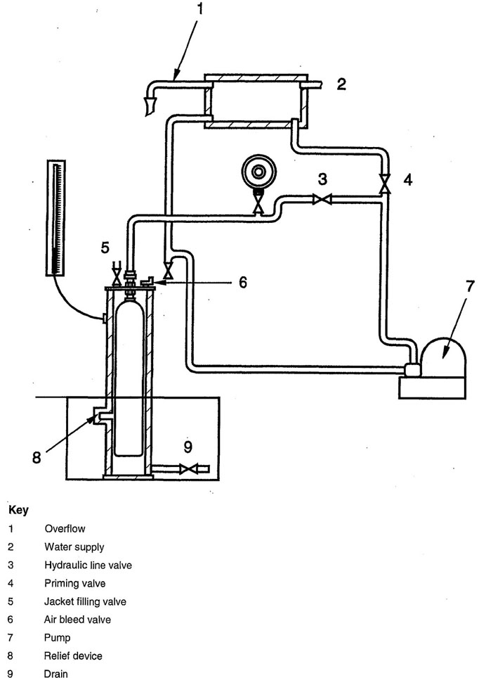
Figure C.2 — Water jacket volumetric expansion test (fixed burette method)
34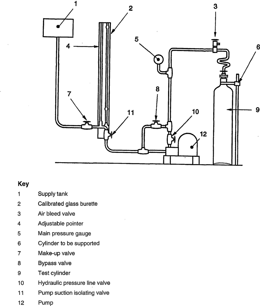
Figure C.3 — Non–water jacket method, diagrammic layout of container testing apparatus
35All threads shall be checked to ensure the thread diameters, form, length and taper are satisfactory.
If threads show signs of distortion, deformation or burring, these faults shall be rectified. Excessive thread damage or serious deformation of the valve body, handwheel, spindle or other components is cause for replacement.
Maintenance of the valve shall include general cleaning together with replacement of elastomers and worn or damaged components, packing and safety devices, where necessary.
Where the use of lubricants/elastomers is permitted, only those approved for the gas service shall be used, particularly oxidising gas service.
After the valve has been re-assembled it shall be checked for leakage and correct operation. This may be done prior to the valve being refitted to the cylinder, or during and after the first gas charge subsequent to the inspection and test of the cylinder.
36At the time of the publication of this Standard, the editions of the following documents were valid. All standards are subject to revision, and the parties to the agreements based on this Standard are encouraged to investigate the possibility of applying the most recent editions of the documents indicated below. Members of ISO and IEC maintain registers of currently valid International Standards.
| Publication | Year | Title | EN/HD | Year |
| ISO 32 | 1977 | Gas cylinders for medical use — Marking for identification of content | EN 1089-3 | 1997 |
| ISO 6406 | 1992 | Periodic inspection and testing of seamless steel gas cylinders | prEN 1968 | |
| ISO 7225 | 1994 | Gas cylinders — Precautionary labels | EN 1089-2 | 1997 |
| ISO 10461 | 1993 | Seamless aluminium-alloy gas cylinders; periodic inspection and testing | prEN 1802 | |
| ISO 11114-1 | 1997 | Transportable gas cylinders — Compatibility of cylinder and valve materials with gas contents — Part 1: Metallic materials | EN ISO 11114-1 | 1997 |
| ISO 11114-2 | 1997 | Transportable gas cylinders — Compatibility of cylinder and valve materials with gas contents — Part 2: Non-metallic materials | EN ISO 11114-2 | 1997 |
| ISO 11191 | 1997 | Gas cylinders — 25E taper thread for connection of valves to gas cylinders — inspection gauges | EN 629-2 | 1996 |
| ISO 11621 | 1997 | Gas cylinders — Procedures for change of gas service | EN 1795 | 1997 |
| ISO 13341 | 1997 | Transportable gas cylinders — Fitting of valves to gas cylinders | EN ISO 13341 | 1997 |
| ISO 13769 | Gas cylinders — Stamp marking | EN 1089-1 | 1997 |
NOTE There is currently no ISO equivalent for prEN 13096.
37