
In order to promote public education and public safety, equal justice for all, a better informed citizenry, the rule of law, world trade and world peace, this legal document is hereby made available on a noncommercial basis, as it is the right of all humans to know and speak the laws that govern them.
INTERNATIONAL STANDARD
ISO
10462
Second edition
2005-02-15
Bouteilles à gaz — Bouteilles transportables pour acétylène dissous — Contrôles et entretien périodiques
Reference number
ISO 10462:2005(E)
© ISO 2005
ii| PDF disclaimer |
| This PDF file may contain embedded typefaces. In accordance with Adobe's licensing policy, this file may be printed or viewed but shall not be edited unless the typefaces which are embedded are licensed to and installed on the computer performing the editing. In downloading this file, parties accept therein the responsibility of not infringing Adobe's licensing policy. The ISO Central Secretariat accepts no liability in this area. Adobe is a trademark of Adobe Systems Incorporated. Details of the software products used to create this PDF file can be found in the General Info relative to the file; the PDF-creation parameters were optimized for printing. Every care has been taken to ensure that the file is suitable for use by ISO member bodies. In the unlikely event that a problem relating to it is found, please inform the Central Secretariat at the address given below. |
© ISO 2005
All rights reserved. Unless otherwise specified, no part of this publication may be reproduced or utilized in any form or by any means, electronic or mechanical, including photocopying and microfilm, without permission in writing from either ISO at the address below or ISO's member body in the country of the requester.
ISO copyright office
Case postale 56 • CH-1211 Geneva 20
Tel. + 41 22 749 01 11
Fax + 41 22 749 09 47
E-mail copyright@iso.org
Web www.iso.org
Published in Switzerland
iii| Page | ||
| Foreword | iv | |
| Introduction | v | |
| 1 | Scope | 1 |
| 2 | Normative references | 1 |
| 3 | Terms and definitions | 1 |
| 4 | Intervals between periodic inspections | 3 |
| 5 | Preparation of gas cylinder | 4 |
| 6 | Inspection and maintenance | 5 |
| 7 | Identification of contents | 8 |
| 8 | Markings | 8 |
| 9 | Records | 8 |
| 10 | Rejection and rendering cylinders unserviceable | 9 |
| 11 | Disposal of unserviceable periods | 9 |
| Annex A (informative) Inspection periods | 10 | |
| Annex B (normative) Procedure to be adopted when de-valving and when it is suspected that a cylinder valve is obstructed | 11 | |
| Annex C (normative) Description and evaluation of defects and conditions for rejection of acetylene gas cylinders at time of visual inspection | 13 | |
| Annex D (informative) Tops of acetylene cylinders containing monolithic porous mass | 16 | |
| Annex E (informative) Illustration of cracks in the porous mass of an acetylene cylinder, and tools and clearance gauges | 18 | |
| Annex F (informative) Inspection and maintenance of valves and their junctions: recommended procedures | 20 | |
| Annex G (informative) Test date rings for gas cylinders | 21 | |
| Bibliography | 22 | |
ISO (the International Organization for Standardization) is a worldwide federation of national standards bodies (ISO member bodies). The work of preparing International Standards is normally carried out through ISO technical committees. Each member body interested in a subject for which a technical committee has been established has the right to be represented on that committee. International organizations, governmental and non-governmental, in liaison with ISO, also take part in the work. ISO collaborates closely with the International Electrotechnical Commission (IEC) on all matters of electrotechnical standardization.
International Standards are drafted in accordance with the rules given in the ISO/IEC Directives, Part 2.
The main task of technical committees is to prepare International Standards. Draft International Standards adopted by the technical committees are circulated to the member bodies for voting. Publication as an International Standard requires approval by at least 75% of the member bodies casting a vote.
Attention is drawn to the possibility that some of the elements of this document may be the subject of patent rights. ISO shall not be held responsible for identifying any or all such patent rights.
ISO 10462 was prepared by Technical Committee ISO/TC 58, Gas cylinders, Subcommittee SC 4, Operational requirements for gas cylinders.
This second edition cancels and replaces the first edition (ISO 10462:1994), which has been technically revised.
vAcetylene cylinders differ from all other cylinders transporting compressed or liquefied gases in that they contain a porous mass and normally a solvent in which the acetylene stored is dissolved. However, for special applications there is also a limited quantity of acetylene cylinders containing a porous mass and no solvent. For the periodic inspection cycle, due regard is to be given to the different types of porous masses. The remainder of this document should be read considering these differences.
The primary objective of the presence of the porous mass is to limit an acetylene decomposition, should it be initiated, and thus prevent a cylinder incident. If some porous mass is missing or if a defect (e. g. a cavity, crack or void of significant size) exists as a result of breakdown or subsidence of the porous mass, then the decomposition could progress at a rate that could cause an explosion.
The requirements dealt with in this document are mainly those that are specific for acetylene cylinders; for more general requirements related to the periodic inspection of gas cylinders, reference is made to the relevant ISO documents.
The periodic inspection of acetylene cylinders is to be performed only by competent persons and, in those jurisdictions requiring it, persons authorized by the regulatory authority.
Due to the presence of a porous mass in the cylinder, neither a hydraulic or pneumatic pressure test, nor a visual inspection of the internal surface of the shell can be carried out.
vi viiGas cylinders — Transportable cylinders for dissolved acetylene — Periodic inspection and maintenance
This International Standard specifies the requirements for periodic inspection of seamless and welded cylinders manufactured from steel or aluminium alloys intended for the transport of acetylene in cylinders of water capacity up to 150 I and the requirements for the periodic inspection and maintenance of acetylene cylinders, regardless of the method of manufacture of the shell.
The following referenced documents are indispensable for the application of this document. For dated references, only the edition cited applies. For undated references, the latest edition of the referenced document (including any amendments) applies.
ISO 3807-1:2000, Cylinders for acetylene — Basic requirements — Part 1: Cylinders without fusible plugs
ISO 3807-2:2000, Cylinders for acetylene — Basic requirements — Part 2: Cylinders with fusible plugs
ISO 13341, Transportable gas cylinders — Fitting of valves to gas cylinders
ISO 13769, Gas cylinders — Stamp marking
For the purposes of this document, the following terms and definitions apply.
transportable unit consisting of two or more acetylene cylinders manifolded together within a rigid frame, equipped with all necessary equipment for filling and emptying in the assembled state
pressure vessel manufactured and suitable for transport of acetylene, containing a porous mass and solvent (where applicable) for acetylene with valve and other accessories fixed to the cylinder
NOTE 1 For solvent-free acetylene cylinders, see Clause 6 of ISO 3807-1;2000 or ISO 3807-2:2000.
NOTE 2 When there is no risk of ambiguity, the word “cylinder” is used.
ratio of the maximum acetylene content to the specified solvent content
1any national body or authority designated or otherwise recognized as such for any purpose in connection with this International Standard
person who by a combination of training, experience and supervision is able to make objective judgments on the subject
cylinder shell ready to be charged with acetylene gas that is complete with porous mass, solvent (where applicable), saturation gas (where applicable), valve and any valve protection permanently fixed to the cylinder shell
pressure vessel manufactured and suitable for receiving and containing a porous mass and to be filled as an acetylene cylinder
company responsible for filling the cylinder shell with porous mass and which generally prepares it for the first charge of acetylene
specified maximum mass of acetylene the cylinder is designed to contain
NOTE 1 Maximum acetylene content is expressed in kilograms.
NOTE 2 When a solvent is used, it includes the saturation gas.
maximum permissible gauge pressure, at a uniform temperature of 15°C, in a cylinder containing the
maximum acetylene content and the specified solvent content
NOTE Maximum permissible settled pressure is expressed in bar.
ratio of the total volume (water capacity) of the cylinder shell minus the volume of the solid material of the porous mass, to the water capacity of the cylinder shell
NOTE Porosity is expressed as a percentage.
single or multi-component material introduced or formed in the cylinder shell in order to fill it and that, due to its porosity, allows the absorption of the solvent and acetylene gas solution
NOTE The porous mass may be monolithic or non-monolithic. Monolithic porous mass consists of a solid product typically obtained by reacting materials or by bonding materials together with a binder. Non-monolithic porous mass consists typically of granular, fibrous or similar materials without addition of a binder.
2liquid that is absorbed by the porous mass and is capable of dissolving and releasing the acetylene
NOTE The following abbreviations are used:
— “A” for acetone;
— “DMF” for dimethylformamide.
reference mass of the acetylene cylinder with the specified amount of solvent
NOTE 1 Tare weight is expressed in kilograms.
NOTE 2 This is further specified in accordance with 3.14.1, 3.14.2 or 3.14.3.
NOTE 3 For cylinders with solvent, the tare weight is expressed by indicating either one or both of the masses corresponding to tare A and tare S. For solvent-free acetylene cylinders, the tare weight is expressed by indicating a tare F. For the tare weight used for cylinders in bundles, see ISO 3807-1 or ISO 3807-2, 7.5.3.
sum of empty mass of the cylinder shell, the mass of the porous substance (see 3.12), the specified mass of solvent, the mass of any coating (e.g. paint) used in service, the mass of the valve including thermocouple where fitted, any fixed valve guard and the mass of all other parts that are permanently attached (e.g. by clamping or bolt fixing) to the cylinder when it is presented for filling
tare A plus the acetylene mass required to saturate the solvent at normal atmospheric pressure (1,013 bar) and at a temperature of 15°C (saturation gas)
NOTE Tare S is expressed in kilograms.
tare A minus the specified mass of solvent
total mass equal to tare A (or tare F for solvent-free cylinders) plus the maximum acetylene content
NOTE Total weight is expressed in kilograms.
actual capacity of the cylinder shell, measured by filling the shell with water
NOTE 1 Water capacity is expressed in litres.
NOTE 2 The cylinder shell is defined as being empty of any porous mass, see 3.7.
A cylinder shall be due for periodic inspection on its first receipt by a filler after the expiry of the interval in accordance with the requirements of the United Nations Recommendations on the Transport of Dangerous Goods, Model Regulations or as specified by national or international authorities (see examples in Annex A).
3Provided the cylinder has been subjected to normal conditions of use and has not been subjected to abusive and abnormal conditions rendering the cylinder unsafe, there is no general requirement for the user to return a gas cylinder before the contents have been used even though the inspection interval may have lapsed.
It is the responsibility of the owner or user to submit the cylinder for a periodic inspection and test within the interval specified by national or international authorities, or as specified in the relevant cylinder design standard if this is shorter.
Before proceeding with the inspection, cylinders shall be depressurized of gas. Cylinders shall be checked for pressure both before and after depressurization. Depressurization shall be carried out in a safe manner having due regard to the characteristics of acetylene. Depressurization shall be carried out over a period long enough to ensure removal of all acetylene, except saturation gas. Precautions shall be taken because variations in temperature influence the quantity of acetylene in the form of saturation gas.
The absence of a positive pressure reading does not clearly indicate the absence of excess gas due to the possibility of a blocked valve (see Annex B).
In case of any doubts regarding the efficiency of the depressurization cycle, the cylinder should be weighed.
A cylinder weighing more than the tare weight (see 3.14) stamped on the cylinder is not always a clear indication of the presence of excess gas. Some relevant factors that have to be considered include a possible excess of solvent or contamination with water, etc.
A cylinder weighing less than or equal to the stamped tare weight is not always a clear indication of the absence of gas under pressure. Some relevant factors that have to be considered include a possible solvent shortage and external corrosion causing a loss of shell weight.
When necessary, the cylinder shall be cleaned and have all loose coatings, corrosion products, tar, oil or other foreign matter removed from its external surface by a suitable method, e.g. by brushing, shot-blasting (under closely controlled conditions to ensure that there is no leakage of acetylene into the brushing or shot-blasting cabinet), water jet abrasive cleaning, chemical cleaning or other suitable methods. The method used to clean the cylinder shall be a validated, controlled process. Care shall be taken at all times to avoid damaging the cylinder and pressure relief devices where fitted or removing excess amounts of cylinder wall (See Annex C).
The external visual inspection in accordance with 6.1 can be carried out at this stage.
NOTE Shot-blasting is a process utilizing iron shot of various sizes. It is not to be confused with or referred to as sand blasting, grit blasting or other more aggressive processes that remove a significant amount of the base metal or metallic coatings, which should not be used.
Before removing the valve from an acetylene cylinder, it shall be determined that the cylinder has been completely depressurized as described in 5.1. If there is any reason to believe that a valve is blocked, e.g. the lack of an audible release of gas when opening the valve, and that the cylinder may still contain residual gas under pressure, checks shall be made, e.g. by introducing an inert gas at a pressure lower than 5 bar and observing its discharge.
If it is found that the valve is obstructed, then a suitable method shall be employed to remove the gas or the valve, taking into consideration the design of the valve and taking all necessary precautions having due regard to the hazards that can result from an uncontrolled operation (see Annex B). De-valving shall take place in the
4open or in a ventilated area. The temperature of the cylinder when removing the value should be close to the ambient temperature to avoid either excess venting of residual gas from the cylinder or ingress of air into the cylinder.
NOTE The cylinders should not be left open or without values longer than necessary for the inspection.
Acetylene cylinders usually contain neck filters/core hole packing consisting of filter/gauze and felts. Neck filters and packing materials placed between the top of the porous mass and the base of the value stem shall be removed, as appropriate, to enable an adequate inspection of the porous mass in accordance with the inspection requirements of the porous mass manufacturer. When the inspection requirements. For various types of neck/core hole filters see Annex D.
Some porous mass manufacturers equip monolithic mass acetylene cylinders with wooden plugs, which from an integral part of the porous mass. These plugs, which are situated below the neck filter/gauze arrangement, shall be left intact and not removed for the purpose of the visual examination if the wooden plug is in the right position permitting the measurement of the gap in accordance with the manufacturer's instruction. If on a previous inspection the wooden plug has been tampered with or removed by mistake, this plug shall be replaced in accordance with the porous mass manufacturer's instructions.
Special care shall always be taken when removing filters or packing material in view of the possibility of some restrictions at the neck with residual pressure underneath, which, if suddenly released, might blow the filter out with some of the porous substance and cause injury. The presence of fine carbon powder on the filters or packing material could indicate a flashback has occurred.
The external surface of each cylinder shall be inspected for
Damaged value guards, threaded neck rings and footings can be repaired or replaced as appropriate. No welding or any heat shall be directly applied to the pressure containing part of the cylinder.
For rejection criteria, see Annex C. Cylinders no longer suitable for future service shall be rendered unserviceable (see Clause 10).
Subject to the requirements of 5.4. the porous mass shall be examined for the presence of visible contamination or other defects that could affect the suppression of an acetylene decomposition. The examination shall be performed by appropriate use of special spark resistant tools such as metal wire probes, rods, feeler or clearance gauges to check the firmness and the presence of voids or other defects in the mass
5(see Annex E). Subclauses 6.2.1 to 6.2.3 give the rejection criteria. Care shall be taken to ensure that the porous mass is not damaged by the inspection tools. See Table C.1, flash back.
The porous mass shall be checked visually for contamination such as presence of significant fine carbon powder (see 5.4), water, or oil deposits or whether there has been a discoloration of the porous mass. Depending on the level of contamination for any of those listed above, the competent person shall decide if the porous mass is to be rejected.
The visual inspection shall verify that the porous mass shows no excessive top clearance (gap between the top of the cylinder and the monolithic porous mass), and no excessive cracking or crumbling.
Cylinders with masses that show cracking or crumbling less than 1 mm width when they do not incorporate break outs or dislodging of the mass are acceptable. Small break outs in the top of the cylinder neck/shoulder area are acceptable as long as the maximum gap is not exceeded at any point. See examples in Annex E in Figure E.1 a) and Figure E.1 b).
The maximum gap between the top of the cylinder and the monolithic porous mass shall not exceed that specified in the type approval for that cylinder. Only those gaps up to the maximum used in the type approval tests shall apply. if such data is unavailable for cylinders with monolithic asbestos-free porous mass, the gap shall not exceed 2 mm. If at a later stage, cylinders with other gap sizes pass the requirements of the flashback test and are approved, then these gap sizes may also apply.
If the cylinder is equipped with a wooden plug (see 5.4) it shall be checked by applying a gentle load that the plug is firmly fixed in its position and there is no significant lateral movement.
Additionally, the porous mass shall be checked to ensure that there is no significant lateral movement, Cylinders showing cavitations or significant lateral movement shall be rejected.
Non-monolithic porous masses that show cavitations or compaction, or a loss of compaction shall be rejected or repaired in accordance with 6.3.
A non-monolithic mass that has been rejected due to cavitation shall only be repaired if the repair does not impair the safety of the cylinder.
The repair of a non-monolithic mass shall be performed according to the instructions of the porous mass manufacturer or according to the instructions of a competent person, and the method to be used shall be verified by testing in accordance with ISO 3807-1 or ISO 3507-2. The quantity of material added shall be recorded, the tare weight of the cylinder adjusted as appropriate and the slump marking adjusted accordingly.
A cylinder that contains a rejected porous mass that is not suitable for repair in accordance with this clause shall be rendered unserviceable or its porous mass shall be replaced according to 6.4.
If the porous mass is no longer acceptable but the external condition of the shell is satisfactory, then either the existing porous mass shall be replaced and the shell refused or the complete cylinder shall be made unserviceable.
6The removal of the existing porous mass and the solvent shall be carried out in a safe manner and the cylinder shall be thoroughly cleaned and inspected. Special care shall be taken if the porous mass contains asbestos.
The internal surface of the cylinder shall be examined for corrosion or other visible defects and, if the shell is found to be satisfactory, it shall be permissible to introduce a new porous mass (see Annex C). Each cylinder shall be hydraulically tested at the stamped test pressure by a competent person prior to reintroducing the new approved porous mass. The marking shall be updated accordingly. See ISO 13769.
Where fusible plugs or other pressure relief devices are used, they shall be examined for damage. Where damage is found, the device shall be replaced and checked for gas tightness.
If a valve or any other accessory is to be reintroduced into service, it shall be inspected and maintained to ensure that it will perform satisfactorily in service and meet the requirements of gas tightness from the valve manufacturing standards, e.g. ISO 10297. An example of a suitable method is given in Annex F.
When the valve is removed, the cylinder to valve threads shall be examined to identify the type of thread (e.g. 25E as specified in ISO 10920) and to ensure that they are
— clean and of full form,
— free of damage,
— free of burrs,
— free of cracks, and
— free of other imperfections.
Cracks manifest themselves as lines that run vertically down the thread and across the thread faces. They should not be confused with tap marks (thread machining stop marks). Special attention should be paid to the area at the bottom of the threads.
Other surfaces of the neck shall also be examined to ensure they are free of cracks or other defects (see Annex C).
Where necessary and where the manufacturer or the competent design authority confirms that the design of the neck permits, threads may be re-tapped or the thread type changed to provide the appropriate number of effective threads. After re-tapping or changing the thread form, the threads shall be checked with the appropriate thread gauge (e.g. ISO 11191 for 25E threads).
When a neck ring/collar is attached, an examination shall be carried out to ensure that it is secure and to inspect for thread damage. A neck ring shall only be changed using an approved procedure. If it is found that
7any significant damage to cylinder material has occurred by replacement of the neck ring/collar, the cylinder shall be rendered unserviceable (see Clause 14).
Cylinders meeting the requirements of this standards shall be reassembled by replacing, as specified by the porous mass manufacturer, any packing materials in the neck end and fitting new filters in such a way as to ensure that when the valve is fitted contact is made between the base of the valve stem and the filters/packings.
New or reconditioned valves shall be fitted to the cylinder using a suitable jointing material and the torque necessary to ensure a gas-tight seal between the valve and the cylinder in accordance with ISO 13341.
Where relevant regulations require, a ring shall be fitted over the stem of the valve prior to the valve being fitted to indicate the date (year) of the next periodic inspection. Annex G provides one example of an existing system for indicating reinspection dates. Other systems are in use.
Before the cylinder is reintroduced into service, the contents shall be identified. As an example, use ISO 7225 and ISO 32.
Each cylinder that passes the shell and porous mass inspection shall be market with the date of the inspection and the symbol of the inspection body or test station in accordance with the relevant standard or regulation, e.g. ISO 13769. Where an alteration of any stamp marking is necessary (e.g. due to a change of the tare weight as a consequence of replacement of a footring, neck ring, guard, valve, or the porous mass or as a consequence of addition of new porous mass), the old markings shall be obliterated (or crossed out) and the new data shall be stamped. A method shall be used that cannot damage the porous mass.
Where relevant regulations require, the next inspection date shall be shown by an appropriate method such as a ring fitted between the valve and the cylinder indicating the date (year) of the next periodic inspection. Annex G provides one example of an existing system for indicating reinspection dates. Other systems are in use and the same systems are used with different colours for the same year.
For monolithic masses, stamping on the shoulder of welded cylinders is not permitted unless a data plate is provided for that purpose or unless it is provided for by the specification to which the cylinder is manufactured. In such cases, the stamping may be on a ring under the valve (see ISO 13769).
A cylinder inspection record shall be retained for 15 years. It shall record sufficient information to positively identify the cylinder and the results of the inspection. The following information shall be available for inspection:
The decision to reject a cylinder may be taken at any stage during the periodic inspection and test procedure. If it is impossible to recover a rejected cylinder, after notifying the owner, the testing station shall make the cylinder unserviceable for holding gas under pressure so it is impossible for any part of the cylinder, especially the shoulder, to be re-issued into service. In case of any disagreement, it shall be ensured that the legal implication of the contemplated action is fully understood.
Prior to taking any of the following actions, ensure that the cylinder is empty (see Clause 5).
The following methods may be employed:
Methods used for disposing of non-acetylene cylinders are inappropriate for acetylene cylinders because of the nature of the contents of an acetylene cylinder.
When disposing of acetylene cylinders, very careful consideration shall be given to the fact that the cylinders could contain residual acetylene, solvent (DMF, acetone) and porous mass, which could contain asbestos.
Disposal should be in accordance with local, provincial and national regulations.
9The following information is outlined in the United Nations Recommendations for the Transport of Dangerous Goods, Model Regulations, thirteenth edition. The most current edition should be consulted.
Packing instruction P200 of the United Nations Recommendations for the Transport of Dangerous Goods, Model Regulations, 13th revised edition, specifies the following:
Special packing provision p: For UN 1001 acetylene, dissolved and UN 3374 acetylene, solvent free, cylinders shall be filled with a homogeneous monolithic porous mass.
For UN 1001 acetylene, dissolved, the test period is 10 years.
For UN 3374 acetylene, solvent free, the test period is 5 years.
It is recommended that an acetylene cylinder be changed with gas only if it has been subjected to a periodic inspection according to the requirements of this standard with the following specified period:
— For cylinders containing a non-monolithic porous mass: For all newly massed cylinders, the first periodic inspection should be performed within 2 years ± 6 months in service. Thereafter, subsequent inspections should be performed every 5 years.
— For cylinders containing a monolithic porous mass: For all newly massed cylinders, the first periodic inspection should be performed after 3 years ± 6 months in service. Thereafter, subsequent inspections should be performed every 10 years.
10The following procedures shall be carried out only by trained personnel. In view of the potential hazards in acetylene cylinders, this operation can lead to injury from stored energy release and fire, hence personnel shall take such precautions as deemed necessary for the work to be performed. When the acetylene, if any, has been released and the pressure within the cylinder has been reduced to atmospheric pressure as described in Clause 5.1, the valve may be removed after an additional check is made to establish that there is free passage through the valve.
As indicated in Clauses 5.1 and 5.3, a systematic check shall be made to establish that the passage through the valve is unobstructed. The method adopted shall be a recognized procedure such as by introducing inert gas at a pressure up to 5 bar and checking its discharge or a procedure that provides equivalent safeguards.
Only when it has been established that there is no obstruction to gas flow in the cylinder valve, may the valve be removed.
When a cylinder is found to have an obstructed gas passage in the valve, the cylinder shall be set aside and handled only by specially trained personnel in this task. The preferred method to follow is to partially unscrew the valve within a glanded cap that is secured and joined to the cylinder and vented to a safe discharge.
The principles of a suitable device are illustrated in Figure B. 1. This procedure shall be performed in a controlled manner in such a way as to avoid personal injury.
11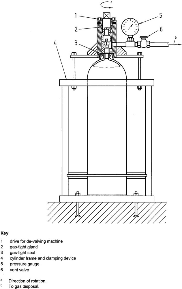
Figure B. 1 — Typical device for the removal of an obstructed gas cylinder valve
12Gas cylinder defects can be physical or material, or due to corrosion as a result of environmental or service conditions to which the cylinder has been subjected during its life.
The object of this annex is to give general guidelines to the gas cylinder users as to the application of rejection criteria, which are identical to those in the seamless-steel, seamless aluminium-alloy and welded-steel periodic inspection and testing standards: ISO 6406, ISO 10461 and ISO 10460, respectively.
Evaluation of physical or material defects in the cylinder shall be in accordance with Table C. 1.
Permanent attachments (e.g. footrings and shrouds) shall be inspected and shall be suitable for their intended purpose.
The cylinder could be subjected to environmental conditions that could cause external corrosion of the metal.
Extensive experience and judgment are required in evaluating whether cylinders that have corroded internally are safe and suitable for return to service. The surface of the metal shall be cleaned of corrosion products prior to the inspection of the cylinder.
13| Type of defect | Definition | Rejection limits in accordance with Clause 6a | Repair or render unserviceable | |
|---|---|---|---|---|
| Bulge | Visible swelling of the cylinder | All cylinders with such a defect | Render unserviceable | |
| Dent | A depression in the cylinder that has neither penetrated nor removed metal and is greater in depth than 1 % of the outside diameter | When the depth of the dent exceeds 3 % of the external diameter of the cylinder or when the diameter of the dent is less than 15 times its depth |
Render unserviceable Render unserviceable |
|
| Cut or gouge | A sharp impression where metal has been removed or redistributed and whose depth exceeds 5 % of the cylinder wall thickness | For seamless-steel or seamless aluminium-alloy cylinder shells: when the depth of the cut or gouge exceeds 15 % of the wall thickness or when the length of the cut or gouge exceeds 25 % of the external diameter of the cylinder |
For welded-steel cylinder shells: when the depth of the cut or gouge exceeds 10 % of the wall thickness of the cylinder or when the length of the cut or gouge exceeds 25 % of the external diameter of the cylinder |
Repair possibleb |
| Crack | A split or rift in the metal | All cylinders with such defects | Render unserviceable | |
| Fire damage | Excessive general or localized heating of a cylinder usually indicated by:
|
All cylinders in categories a) and b) All cylinders in categories c) and d) may be acceptable after inspection and testing |
Render unserviceable Repair possible. In case of doubt, render unserviceable |
|
| Flash back | Ignition of acetylene within the cylinder | All cylinders with such a defect | Render unserviceable | |
| Plug or neck inserts | Additional inserts fitted in the cylinder neck or base | All cylinders unless it can be clearly established that addition is part of approved design | Repair possible | |
| Stamping | Marking by means of a metal punch | All cylinders with illegible or incorrect markings (see 6.4) | Render unserviceablec | |
| Arc or torch burns | Partial melting of the cylinder, the addition of weld metal or the removal of metal by scarfing or cratering | All cylinders with such defects | Render unserviceable | |
| Suspicious marks | Marks introduced other than by the cylinder manufacturing process and approved repair | All cylinders with such defects | Continued use possible after additional inspection | |
| a When applying the rejection criteria, the conditions of use of the cylinders, the severity of the defect and safety factors in the design shall be taken into consideration. b Repair is possible provided that after repair by a suitable metal removal technique, the remaining wall thickness is at least equal to the minimum guaranteed wall thickness. c If it can be clearly established that the cylinder fully complies with the appropriate specifications, altered operational and modified markings may be acceptable and inadequate markings may be corrected, provided there is no possibility of confusion. |
||||
The types of corrosion shall in general be classified as in Table C. 2.
| Types of corrosion | Definition | Rejection limits in accordance with Clause 6a | Repair or render unserviceable |
|---|---|---|---|
| General corrosion | Loss of wall thickness over an area of more than 20% of either the interior or exterior total surface area of the cylinder | If the original surface of the metal is no longer recognizable or If the depth of penetration exceeds 10% of the original thickness of wall or If the wall thickness is less than minimum guaranteed wall thickness |
Repair possibleb Repair possibleb Render unserviceablec |
| Local corrosion | Loss of wall thickness over an area of less than 20% of the total surface area of the cylinder, except for the other types of local corrosion described below | If the depth of penetration exceeds 20% of the original thickness of the cylinder wall or If the wall thickness is less than minimum guaranteed wall thickness |
Repair possibleb Render unserviceablec |
| Chain, pitting or line corrosion | Corrosion forming a narrow longitudinal or circumferential line or strip, or isolated craters or pits that are almost connected | If the total length of corrosion in any direction exceeds the diameter of the cylinder and the possible depth exceeds 10% of the original wall thickness | Repair possibleb |
| Crevice corrosion | Corrosion associated with and taking place at or immediately around an aperture | If, after thorough cleaning, the depth of penetration exceeds 20% of the minimum guaranteed wall thickness | Repair possibleb |
| a If the bottom of the defect cannot be seen and if its extent cannot be determined using appropriate equipment, the cylinder must be rendered unserviceable. b Repair is possible provided that after repair by a suitable metal removal technique, the remaining wall thickness is at least equal to the minimum guaranteed wall thickness. c If corrosion has reached limits of depth or extent, the remaining wall thickness should be checked with an ultrasonic device. The wall thickness may be less than the design minimum, e.g., small (depth and extent) isolated pits, where authorized by the relevant regulations taking into consideration the severity of the defect and safety factors. |
|||
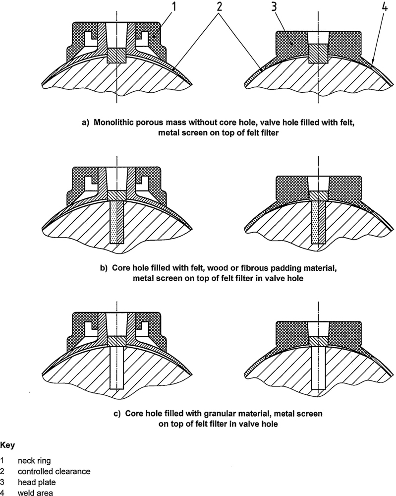
Figure D.1 — Diagram of the tops of seamless (left) and welded (right) acetylene cylinders containing monolithic porous mass: types without pressure relief devices
16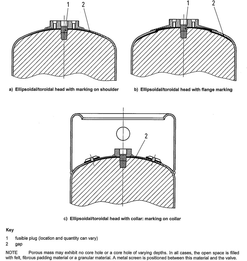
Figure D.2—Diagram of acetylene cylinders with ellipsoidal tops containing monolithic porous mass: types with pressure relief devices
17E.1 Figure E. 1 a) shows an acetylene cylinder with mass that shows cracking and crumbling but that could be acceptable for further service. The cylinder may be further used provided there are no break-outs and the porous mass cannot be dislodged.
E.2 Figure E. 1 b) shows an acetylene cylinder with a mass that shows cracking and crumbling and that shall be rejected.
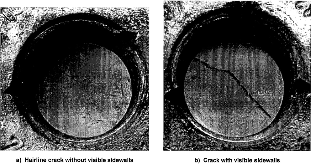
Figure E.1 — Cracks in the monolithic porous mass of an acetylene cylinder
18E.3 Figure E.2 shows examples of top clearance gauges.
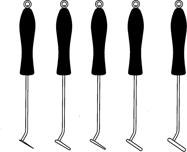
Figure E.2 — Examples of top clearance gauges for monolithic porous mass
19All threads shall be checked to ensure the thread diameters, form, length and taper are satisfactory.
If threads show sings of distortion, deformation or burring, these faults shall be rectified. Excessive thread damage or serious deformation of the valve body, handwheel, spindle or other components is cause for replacement.
Maintenance of the valve shall include general cleaning together with replacement of elastomers and worn or damaged components, packing and pressure relief devices, where necessary.
Where the use of lubricants/elastomers is permitted, they shall be compatible with both the solvent and acetylene in accordance with ISO 11114-2.
After the valve has been reassembled, it shall be checked for correct operation and shall undergo internal and external leak checks at intended operating pressure (for example, see ISO 10297 and ISO 14246). This may be done prior to the valve being refitted to the cylinder.
20NOTE Systems other than the one specified in Table G. 1 are in use, and the same system is used with different colours.
| Year | Colour | Shape |
|---|---|---|
| 2000 | Aluminium | Circle |
| 2001 | Red | Hexagon |
| 2002 | Blue | Hexagon |
| 2003 | Yellow | Hexagon |
| 2004 | Green | Hexagon |
| 2005 | Black | Hexagon |
| 2006 | Aluminium | Hexagon |
| 2007 | Red | Square |
| 2008 | Blue | Square |
| 2009 | Yellow | Square |
| 2010 | Green | Square |
| 2011 | Black | Square |
| 2012 | Aluminium | Square |
| 2013 | Red | Circle |
| 2014 | Blue | Circle |
| 2015 | Yellow | Circle |
| 2016 | Green | Circle |
| 2017 | Black | Circle |
| 2018a | Aluminium | Circle |
| 2019 | Red | Hexagon |
| 2020 | Blue | Hexagon |
| 2021 | Yellow | Hexagon |
| 2022 | Green | Hexagon |
| 2023 | Black | Hexagon |
| 2024 | Aluminium | Hexagon |
| a The sequence of colour and shape of test date rings is to be repeated on an 18-year cycle. Hence, 2018 is a repeat of 2000. | ||
ICS 23.020.30
Price based on 22 pages
24