
In order to promote public education and public safety, equal justice for all, a better informed citizenry, the rule of law, world trade and world peace, this legal document is hereby made available on a noncommercial basis, as it is the right of all humans to know and speak the laws that govern them.
INTERNATIONAL STANDARD
ISO
10461
Second edition
2005–02–15
Bouteilles à gaz — Bouteilles à gaz sans soudure en alliage d'aluminum — Controles et essais periodiques
Reference number
ISO 10461:2005(E)
© ISO 2005
ii| PDF disclaimer |
| This PDF file may contain embedded typefaces. In accordance with Adobe's licensing policy, this file may be printed or viewed but shall not be edited unless the typefaces which are embedded are licensed to and installed on the computer performing the editing. In downloading this file, parties accept therein the responsibility of not infringing Adobe's licensing policy. The ISO Central Secretariat accepts no liability in this area. Adobe is a trademark of Adobe Systems Incorporated. Details of the software products used to create this PDF file can be found in the General Info relative to the file; the PDF-creation parameters were optimized for printing. Every care has been taken to ensure that the file is suitable for use by ISO member bodies. In the unlikely event that a problem relating to it is found, please inform the Central Secretariat at the address given below. |
© ISO 2005
All rights reserved. Unless otherwise specified, no part of this publication may be reproduced or utilized in any form or by any means, electronic or mechanical, including photocopying and microfilm, without permission in writing from either ISO at the address below or ISO's member body in the country of the requester.
ISO copyright office
Case postable 56 • CH–1211 Geneva 20
Tel. +41 22 749 01 11
Fax +41 22 749 09 47
E-mail copyright@iso.org
Web www.iso.org
Published in Switzerland
iii| Page | |
| Foreword | iv |
| Introduction | v |
| 1 Scope | 1 |
| 2 Normative reference | 1 |
| 3 Intervals between periodic inspections and tests | 1 |
| 4 List of procedures for periodic inspections and tests | 2 |
| 5 Identification of cylinder and preparation for inspections and tests | 2 |
| 6 Depressurization and de–valving procedures | 2 |
| 7 External visual inspection | 3 |
| 8 Check of internal condition | 4 |
| 9 Supplementary tests | 4 |
| 10 Inspection of cylinder neck | 5 |
| 11 Pressure test or ultrasonic examination | 5 |
| 12 Inspection of valve and other accessories | 15 |
| 13 Cylinders repairs | 15 |
| 14 Final operations | 15 |
| 15 Rejection and rendering cylinders unserviceable | 18 |
| Annex A (informative) Intervals between periodic inspections and tests | 19 |
| Annex B (informative) Description and evaluation of defects and conditions for rejection of seamless aluminium-alloy gas cylinders at time of visual inspection | 20 |
| Annex C (informative) Procedure to be adopted when de-valving and/or when it is suspected that a cylinder valve is obstructed | 25 |
| Annex D (informative) Cleaning of aluminium-alloy gas cylinders | 28 |
| Annex E (informative) Volumetric expansion testing of gas cylinder | 29 |
| Annex F (informative) Inspection and maintenance of valves and their junctions: recommended procedures | 37 |
| Annex G (informative) Test date rings for gas cylinders | 38 |
| Bibliography | 39 |
ISO(the international Organization for Standardization) is a worldwide federation of national standards bodies (ISO member bodies). The work of preparing International Standards is normally carried out through ISO technical committees. Each member body interested in a subject for which a technical committee has been established has the right to be represented on that committee. International organizations, governmental and non-governmental, in liaison with ISO, also take part in the work. ISO collaborates closely with the International Electrotechnical Commission (IEC) on all matters of electrotechnical standardization.
International Standards are drafted in accordance with the rules given in the ISO/IEC Directives, Part 2.
The main task of technical committees is to prepare International Standards. Draft International Standards adopted by the technical committees are circulated to the member bodies for voting. Publication as an International Standard requires approval by at least 75% of the member bodies casting a vote.
Attention is drawn to the possibility that some of the elements of this document may be the subject of patent rights. ISO shall not be held responsible for identifying any or all such patent rights.
ISO 10461 was prepared by Technical Committee ISO/TC 58, Gas cylinders, Subcommittee SC 4, Operational requirements for gas cylinders
This second edition cancels and replaces the first edition (ISO 10461:1993), which has been technically revised.
vThe principal aim of a periodic inspection and testing procedure is to be satisfied that at the completion of the inspection and test, the cylinders (single or those from bundles) can be reintroduced into service for a further period of time.
The inspection and test are to be carried out only by persons who are authorized under the relevant regulations and competent in the subject to assure all concerned that the cylinders are fit for continued safe use.
The results of inspection and testing for the cylinders that are specified in this International Standard determine whether a cylinder should be returned to service.
vi viiGas cylinders — Seamless aluminium-alloy gas cylinders — Periodic inspection and testing
This International Standard deals with seamless aluminium-alloy transportable gas cylinders intended for compressed and liquefied gases under pressure, of water capacity from 0,5 l to 150 l; it also applies, as far as practical, to cylinders of less than 0,5 l water capacity.
This International Standard specifies the requirements for periodic inspection and testing to verify the integrity of such gas cylinders for further service.
This International Standard does not apply to periodic inspection and testing of acetylene cylinders or composite cylinders with aluminium-alloy liners.
The following referenced documents are indispensable for the application of this document. For dated references, only the edition cited applies. For undated references, the latest edition of the referenced document (including any amendments) applies.
ISO 9712, Non-destructive testing — Qualification and certification of personnel
ISO 11114-2:2000, Transportable gas cylinders — Compatibility of cylinder and valve materials with gas contents — Part 2: Non-metallic materials
ISO 11621, Gas cylinders — Procedures for change of gas service
ISO 13341, Transportable gas cylinders — Fitting of valves to gas cylinders
ISO 13769, Gas cylinders — Stamp marking
A cylinder shall be due for a periodic inspection and test on its first receipt by a filler after the expiry of the interval in accordance with the requirements of the United Nations Recommendations on the Transport of Dangerous Goods, Model Regulations or as specified by national or international authorities (see examples in Annex A).
Provided the cylinder has been subjected to normal conditions of use and has not been subjected to abusive and abnormal conditions rendering the cylinder unsafe, there is no general requirement for the user to return a gas cylinder before the contents have been used even though the periodic inspection and test interval may have lapsed.
It is the responsibility of the owner or user to submit the cylinder for a periodic inspection and test within the interval specified by national or international authorities, or as specified in the relevant cylinder design standard if this is shorter.
1Each cylinder shall be submitted to periodic inspections and tests. The following procedures, where applicable, form the requirements for such inspections and tests and are explained more fully in later clauses:
It is recommended that these procedures be performed in the sequence listed. In particular, the check of internal condition (Clause 8) should be carried out before the pressure test or, although not required, before the ultrasonic examination (Clause 11).
Cylinders that fail an inspection or test shall be rejected (see Clause 15). Where a cylinder passes the above procedures, but when the condition of the cylinder remains in doubt, additional tests shall be performed to confirm its suitability for continued service (see Clause 9) or the cylinder shall be rendered unserviceable.
Depending on the reason for the rejection, some cylinders may be recovered (see Annex B).
The inspections and tests shall be carried out only by persons who are competent in the subject and authorized under the relevant regulations.
Mechanical properties of aluminium-alloy cylinders can be affected by heat exposure. Therefore, the maximum temperature for any operation shall be limited according to the manufacturer's recommendations (see 14.2.2).
Before any work is carried out, the relevant cylinder data (e.g. see ISO 13769) and its contents and ownership shall be identified (e.g. from the labelling and stamping). Cylinders with incorrect or illegible markings or unknown gas contents shall be set aside for special handling.
Cylinders to be internally inspected or tested by a pressure test are required to be depressurized and devalved. Cylinders not internally visually inspected and tested by ultrasonic examination do not require complete depressurization and de-valving unless the ultrasonic examination indicates there is an unacceptable flaw present and the inspector wishes to further investigate (see 11.4.6).
2Cylinders shall be depressurized in a safe, controlled manner before proceeding. Particular attention shall be given to cylinders containing flammable, oxidizing, corrosive or toxic gases to eliminate risks at the internal inspection stage.
Before removing any pressure-retaining accessory (valve, flange, etc.), a positive check shall be performed to ensure that the cylinder does not contain any gas under pressure. This can be performed as described in Annex C using a device such as shown in Figure C. 1.
Cylinders with inoperative or blocked valves shall be treated as outlined in Annex C.
Similarly in the case of cylinders disassembled from bundles not equipped with cylinder valves, the connecting tee junctions shall also be checked to determine whether the gas is able to pass freely from the cylinders using for example the device shown in Figure C.1.
Provided the requirements previously stated have been complied with, the cylinder shall be depressurized safely and the valve shall be removed.
Cylinders shall be depressurized below 5 bar to perform ultrasonic examination.
For cylinders being inspected by the ultrasonic method, refer to Clause 8.
If a cylinder's external condition prevents or hinders a proper visual inspection of the surface, then the cylinder shall be prepared before the inspection. The cylinder shall be cleaned and have all loose coatings, corrosion products, tar, oil or other foreign matter removed from its external surface by a suitable method, e.g. brushing, water jet abrasive cleaning, chemical cleaning or other suitable methods (see Annex D or consult the cylinder manufacturer). Alkaline solutions and paint strippers that are harmful to aluminium and its alloys shall not be used. The method used to clean the cylinder shall be a validated, controlled process. Care shall be taken at all times to avoid damaging the cylinder or removing excess amounts of cylinder wall (see Annex B).
If fused nylon, polyethylene or a similar coating has been applied and the coating is seen to be damaged or it prevents a proper inspection, then the coating shall be stripped. If the coating has been removed by the application of heat at a temperature exceeding the limits specified in 14.2.2 or shows signs of heat damage, the manufacturer shall be consulted before the cylinder is returned into service and the necessary tests and inspections carried out.
The external surface of each cylinder shall then be inspected for
When inspecting for corrosion [see c)], special attention shall be given to areas where water could be trapped. These include the entire base area, the junction between the body and the foot ring and the junction between the body and the shroud.
For rejection criteria, see Annex B. Cylinders no longer suitable for future service shall be rendered unserviceable (see Clause 15).
Cylinders shall be inspected internally to complete periodic inspection and testing requirements.
When the valve is removed, an internal visual inspection shall be performed.
For cylinders being examined by the ultrasonic method in lieu of the pressure test and when reference notches as specified in 11.4.4.2.2 are used for calibration, the valve need not be removed. However, for aluminium-alloy cylinders susceptible to sustained-load cracking, such as those manufactured from IAA 6351A or IAA 6082A alloy, the shoulder and neck area shall be internally visually inspected; alternative non-destructive examination methods, such as eddy current or ultrasonic examination, may be used if approved by the competent authority.
For cylinders that are internally visually inspected, adequate illumination shall be used to identify any defects similar to those listed in 7.2 a) and 7.2 c). Precautions shall be taken to ensure that the method of illumination presents minimum safety risk to the inspector while performing this operation. Any internal liner or coating that may obstruct optimum internal visual inspection shall be removed. Any cylinder showing presence of foreign matter or signs of more than light surface corrosion shall be cleaned internally by water jet abrasive cleaning, flailing, steam jet, hot water jet, chemical cleaning, blasting with glass beads or other suitable method (see Annex D or consult the cylinder manufacturer). Blasting with material other than aluminium or glass beads shall be avoided; hard media could embed itself in the aluminium and result in contamination of the contents. Alkaline solutions and paint strippers that are harmful to aluminium and its alloys shall not be used. The method used to clean the cylinder shall be a validated, controlled process. Care shall be taken at all times to avoid damaging the cylinder or removing excess amounts of cylinder wall in accordance with Annex B. If cleaning is required, the cylinder shall be re-inspected after the cleaning operation.
For cylinders of non-corrosive gases and <0,5 l water capacity with an internal neck diameter < 9 mm, the following alternative methods may be substituted for the internal visual inspection.
— Looking for free moisture at the time of degassing the cylinder whilst in an inverted position and prior to valve removal. If any moisture is present, the cylinder shall be rendered unserviceable.
— Looking for contamination, e.g. in the water used after the hydraulic test. If contamination is observed in the hydraulic test fluid, the cylinder shall be rendered unserviceable.
Where there is doubt concerning the type and/or severity of a defect found on visual inspection, additional tests or methods of examination shall be applied, e.g. ultrasonic techniques, check weighing or other non-destructive tests.
When a hardness test is performed (e.g. see ISO 6506) or an alternative method is used (e.g. conductivity), it shall meet at least the minimum required design hardness value. An alternative method may only be used if it was employed at the time of cylinder manufacture, approved for use by the authorized body, and results and approval recorded accordingly. When this value is not known, the cylinder shall be hardness tested both before and after the stoving operation, and there shall be no appreciable decrease in the hardness value. All hardness tests shall be performed on the parallel section of the cylinder, taking adequate care to ensure deep impressions are not formed and deflection of the sidewall does not occur.
4When the valve is removed, the cylinder to valve threads shall be examined to identify the type of thread (e.g. see ISO 11191 for 25E) and to ensure that they are
— clean and of full form,
— free of damage,
— free of burrs,
— free of cracks – examine thoroughly for evidence of cracks (see Annex B),
— free of other imperfections, e.g. corrosion.
Cracks manifest themselves as lines that run vertically down the thread and across the thread faces (see Figure B.6). They should not be confused with tap marks (thread machining stop marks) (see Figure B.7). Special attention shall be paid to the area at the bottom of the threads for the detection of shoulder cracks or other defects (see Figure B.8).
Other surfaces of the neck shall also be examined to ensure they are free of cracks or other defects (see Annex B).
Where necessary and where the manufacturer or the competent design authority confirms that the design of the neck permits, threads may be re-tapped only by competent persons to provide the appropriate number of effective threads. After re-tapping, the threads shall be checked with the appropriate thread gauge, e.g. ISO 11191 for 25E threads.
When a neck ring/collar is attached, an examination shall be carried out to ensure that it is secure and to inspect for external thread damage. A neck ring shall only be changed using an approved procedure. If it is found that any significant damage to cylinder material has occurred by replacement of the neck ring/collar, the cylinder shall be rendered unserviceable. If the neck ring has been reattached by welding or brazing, the cylinder shall be rendered unserviceable.
Each cylinder shall be submitted to either a pressure test or an ultrasonic examination.
WARNING — Appropriate measures shall be taken to ensure safe operation and to contain any energy released. It should be noted that pneumatic pressure tests require more precautions than hydraulic pressure tests since, regardless of the size of the container, any error in carrying out this test is highly likely to lead to a rupture under gas pressure. Therefore, these tests shall be carried out only after ensuring that the safety measures satisfy the safety requirements.
Each cylinder subjected to a hydraulic pressure test shall use a suitable liquid, normally water, as the test medium. The hydraulic pressure test may be a proof pressure test or a volumetric expansion test as appropriate to the design specification of the cylinder. The hydraulic proof pressure test may be replaced by a pneumatic
5proof pressure test. Having decided to use one particular type of test, its result shall be final. The test pressure shall be in accordance with the stamp markings of the cylinder.
Once a cylinder has failed one of the above-mentioned tests, none of the other test methods shall be applied to approve the cylinder.
The following proposes a typical method for carrying out the test. Any cylinder failing to comply with the requirements of a proof pressure test shall be rendered unserviceable.
This test requires that the pressure in the cylinder be increased gradually until the test pressure is reached. The cylinder test pressure shall be held for at least 30 s with the cylinder isolated from the pressure source, during which time there shall be no decrease in the recorded pressure or evidence of any leakage. Adequate safety precautions shall be taken during the test.
11.2.2.1 All rigid pipe work, flexible tubing, valves, fittings and components forming the pressure system of the test equipment shall be designed to withstand a pressure of at least 1,5 times the maximum test pressure of any cylinder that could be tested.
11.2.2.2 Pressure gauges shall be to Industrial Class 1 (± 1% deviation from the end value) with a scale appropriate to the test pressure (e.g. EN 837-1 or EN 837-3). They shall be checked for accuracy against a calibrated master gauge at regular intervals and in any case not less than once a month. The master gauge shall be calibrated in accordance with national requirements. The pressure gauge shall be chosen so that the test pressure is between approximately one-third and two-thirds of the value capable of being measured on the pressure gauge.
11.2.2.3 The design and installation of the equipment, the connection of the cylinders and the operating procedures shall be such as to avoid trapping air in the system when a liquid medium is used.
11.2.2.4 All joints within the system shall be leak tight.
11.2.2.5 A suitable system control device shall be fitted to the test equipment to ensure that no cylinder is subjected to a pressure in excess of its test pressure by more than the tolerances specified in 11.2.3.3.
11.2.3.1 More than one cylinder may be tested at a time provided that they all have the same test pressure. If individual test points are not used, then in case of leakage all cylinders being tested shall be individually retested.
11.2.3.2 Before applying pressure, the external surface of the cylinder shall be dry.
11.2.3.3 The pressure applied shall not be below the test pressure and shall not exceed the test pressure by 3 % or 10 bar, whichever is lower.
11.2.3.4 On attaining the test pressure, the cylinder shall be isolated from the pump and the pressure held for a minimum period of 30 s.
11.2.3.5 If there is a leakage in the pressure system, it shall be corrected and the cylinders retested.
6During the 30 s hold period the pressure as registered on the pressure gauge shall remain constant.
There shall be absence of visible leakage on the entire surface of the cylinder. This check can be made during the 30 s hold. There shall be no visible permanent deformation.
Annex E proposes typical methods for carrying out the test and gives details for determining the volumetric expansion of seamless aluminium-alloy gas cylinders by the preferred water jacket method or the non-water jacket method. The test methods, equipment and procedure chosen shall be approved by the authorized body. The water jacket volumetric expansion test shall be carried out on equipment with a levelling burette, with a fixed burette or with a weigh bowl. Care should be taken that the entire external surface of the cylinder is wet without any bubbles.
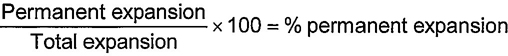
The permanent volumetric expansion of the cylinder expressed as a percentage of the total expansion at test pressure shall not exceed the percentage given in the design specification after the cylinder has been held at test pressure for a minimum period of 30 s. If this figure for permanent expansion is exceeded, in the cylinder shall be rendered unserviceable.
The ultrasonic examination on gas cylinders as described below is based on the ultrasonic examination of pipes according to ISO 9305, ISO 9764 and ISO 10543. The special geometrical features of gas cylinders and the boundary conditions for periodic inspections have been taken into account.
The ultrasonic examination (UE) of seamless aluminium-alloy gas cylinders (water capacity ≥ 2 1) within the framework of periodic inspections may be carried out in lieu of the tests specified in 11.2 and 11.3.
11.4.3.1 General
The cylindrical part of the cylinder, the transition to the shoulder, the transition at the base and critical zones of the base shall be examined ultrasonically with the help of an automated examination device (e.g. Figure 1). For aluminium-alloy cylinders susceptible to sustained-load cracking, such as those manufactured from IAA 6351 or IAA 6082 alloy, the transition area from the shoulder to the neck shall be examined. When such an examination device is not able to do this outside the cylindrical part, a supplementary manual examination shall be performed.
Cylinders that are suspected of fire or heat damage shall not be examined ultrasonically.
7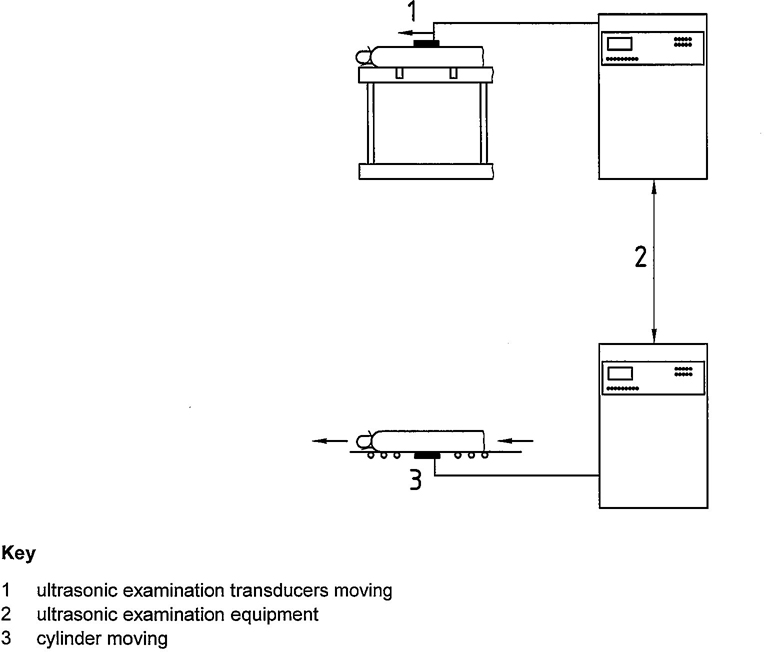
Figure 1 — Examples of two types of ultrasonic examination devices for gas cylinders
11.4.3.2 Examination equipment
The installation shall be able to scan the whole surface of the cylindrical part of the cylinder, including the adjacent transitions to the base and shoulder. An examination system shall have a number and type of transducers and different beam directions required to identify all the reference features in the calibration piece. Such an installation may have five or more ultrasonic transducers suitably arranged (e.g. Figure 2).
Other arrangements of transducers may be possible provided that longitudinal and transverse defects can be detected.
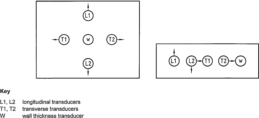
Figure 2 — Examples of the arrangement of transducers
8Any ultrasonic method (e.g. the pulse echo, guided wave) that demonstrates the ability to detect defects and to measure wall thickness shall be used. The most common techniques used today are the contact or the immersion type. Other techniques may be used. See Figure 3 as an example.
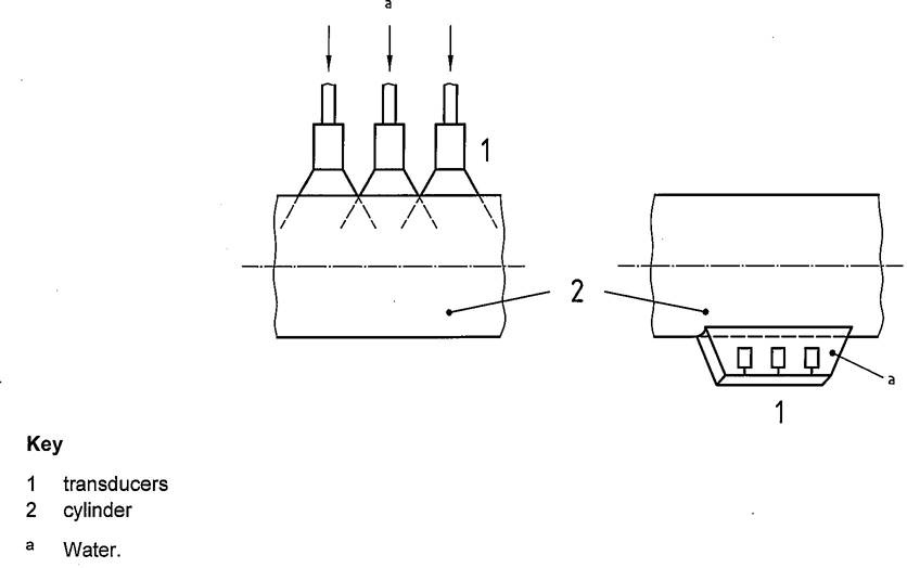
Figure 3 — Examples of coupling techniques
The cylinder wall shall be examined using UE transducers capable of detecting the specified calibration notches. The examination shall cover longitudinal defects in both circumferential directions (clockwise and counter clockwise) and transverse defects in both longitudinal directions (forward and backward) and consider these defects to be located on the internal and external surfaces.
The cylinder wall shall be examined using UE transducers capable of detecting the specified minimum guaranteed wall thickness using a normal transducer (angle of refraction 0°). The accuracy of the system shall be ±5% or ± 0,1 mm, whichever is greater. The inaccuracy shall be taken into account when verifying the wall thickness.
The cylinders to be examined and the search unit with the transducers shall go through a rotating motion and translation relative to one another. The speeds of translation and rotation shall not exceed the speed used during calibration.
The ultrasonic examination unit shall have a screen capable of depicting the various defects present in the calibration cylinder. The installation shall have an automatic alarm when a fault signal (defect or below-minimum guaranteed wall thickness) is registered that alerts the operator for each transducer to ensure that its accuracy is maintained. See Figure 4.
A distinction in the defect detection between internal and external flaws shall be possible.
9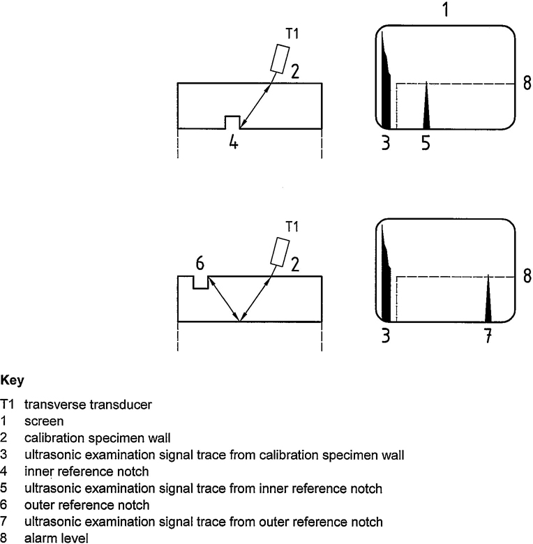
Figure 4—Flaw alarm examples
11.4.3.3 Manual ultrasonic unit
The requirements in 11.4.3.2 shall apply as appropriate for the selection of the transducers and servicing of the unit.
11.4.3.4 Cylinders
The outer and inner surfaces of any cylinder to be examined ultrasonically shall be in a suitable condition for an accurate and reproducible test. In particular, the external surface shall be free of corrosion, non-adhering paint, dirt and oil. An ultrasonic examination is only meaningful when the noise signals caused by the surface are at least 50 % below the corresponding reference signal.
11.4.3.5 Personnel
The examination equipment shall be operated and its operation supervised by qualified and experienced personnel only, as defined in ISO 9712. The tester may be certified to ISO 9712 Level I for ultrasonic examination; however, the Level I operator shall be supervised by a Level II operator. The testing organization shall retain a Level III operator (company employee or a third party) to oversee the entire ultrasonic examination programme.
1011.4.4.1 General
Calibration of the UE defect examination and wall thickness measurement shall use a calibration specimen with notches. A specimen of convenient length shall be prepared from a cylinder representative of the cylinder to be tested with the same nominal diameter, wall thickness, external surface finish and material with similar acoustic properties as the cylinder under test. The standard reference (reference cylinder or calibration cylinder) shall have a known minimum guaranteed wall thickness (tm) that is less than or equal to the cylinder under test.
11.4.4.2 Defect detection
11.4.4.2.1 UE notch requirements and dimensions
For manual and mechanized defect examination purposes, a minimum of four rectangular notches are required as reference notches in the calibration specimen, (see e.g. Figure 5). The notches can be produced either by means of electrical erosion or sawing, or by machining. The bottom corners of the notch may be rounded. The notches shall be located such that there is no interference from any other defect in the reference standard. The form and dimensions of the reference standard shall be verified. The four notches shall be as follows:
— inner notch in longitudinal direction;
— inner notch in transverse direction;
— outer notch in longitudinal direction;
— outer notch in transverse direction.
They shall have the following dimensions in each case:
| Length L: | 50 mm; |
| Depth D: | less than or equal to 10 % of actual measured wall thickness S of the calibration piece located in the sidewall at a location that does not exceed 115 % of the minimum guaranteed wall thickness with an absolute minimum of 0.2 mm and an absolute maximum of 2 mm; |
| Width W: | ≤2D |
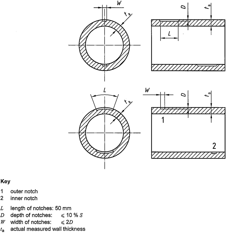
Figure 5 — Examples of reference notches
11.4.4.2.2 Internal inspection notch requirements
When using ultrasonic examination in lieu of an internal visual inspection as specified in Clause 8, one of the following reference notch groupings shall be required.
— Internal longitudinal and transverse reference notches with the dimensions as previously specified, except that the depth shall be (5±1)% of the minimum guaranteed wall thickness.
— 10% internal longitudinal and transverse reference notches with the dimensions as previously specified for the four notches and a flat bottom hole (FBH) with a depth of one-third of the minimum guaranteed wall thickness and a diameter less than or equal to 2 times the minimum guaranteed wall thickness (see Figure 6).
12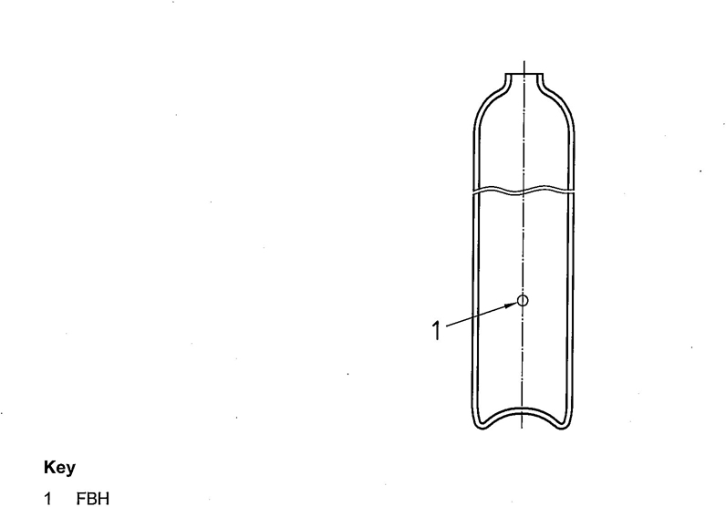
Figure 6—Typical flat bottom hole (FBH) notch
11.4.4.2.3 Calibration procedures
During the calibration procedure, the ultrasonic examination equipment shall be adjusted in such a way that the amplitude of the echoes from the reference notches equals the alarm level (see e.g. Figure 7). This alarm level shall be set to at least 50 % of the screen height. On automated systems, this step shall be performed dynamically. This sensitivity is the reference sensitivity.
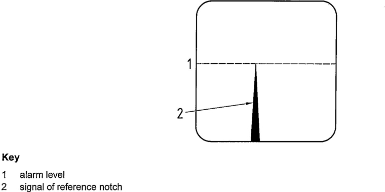
Figure 7 — Reference notch amplitude
11.4.4.3 Wall thickness
To calibrate the manual and mechanized wall thickness measurement, a local thin area (LTA) with a diameter equal to at least 2 times the effective beam width at the point of entrance on the calibration specimen shall be used, the exact wall thickness being known.
The minimum guaranteed wall thickness of the gas cylinder known from the type approval is set as the alarm level in the evaluation unit of the ultrasonic wall thickness measuring device.
1311.4.4.4 Frequency of calibration
The UE equipment shall be calibrated at least at the beginning and at the end of each operator shift, regardless of length, and any time equipment is changed (e.g. change of transducer). Calibration shall also be undertaken at the end of operations that are of a duration less than that of a normal shift. If, during the calibration, the presence of the respective reference notch is not detected, all cylinders examined subsequently to the last acceptable calibration shall be re-examined after the equipment has been recalibrated.
11.4.5.1 Defect detection in cylindrical part by automated installation
The cylindrical part of the cylinder and the transitions to the shoulder and to the base shall be examined for longitudinal and transverse defects using an automated examination device.
The pulse repetition rate of the transducers, rotational speed of the cylinder, and axial speed of the scanning head shall be mutually adjusted in such a way that the system is capable of locating all of the calibrating flaws. At no time shall the speeds used during calibration be exceeded during the examination. It shall be ensured that the system provides 100 % coverage of the surface being examined. When applicable, e.g. a helix-based system, at least 10 % overlap shall be guaranteed.
11.4.5.2 Wall thickness measurement by automated installation
The cylindrical part shall be examined 100 % for wall thinking.
Gas cylinders examined to the examination sensitivity in accordance with 11.4.4.2 and 11.4.4.3 where no defect signal above the alarm level has been recorded have passed the examination. Where a defect signal above the alarm level (defect or below minimum guaranteed wall thickness) has been recorded (see e.g. Figure 8), the cylinder shall be re-evaluated in accordance with Annex B or scrapped.
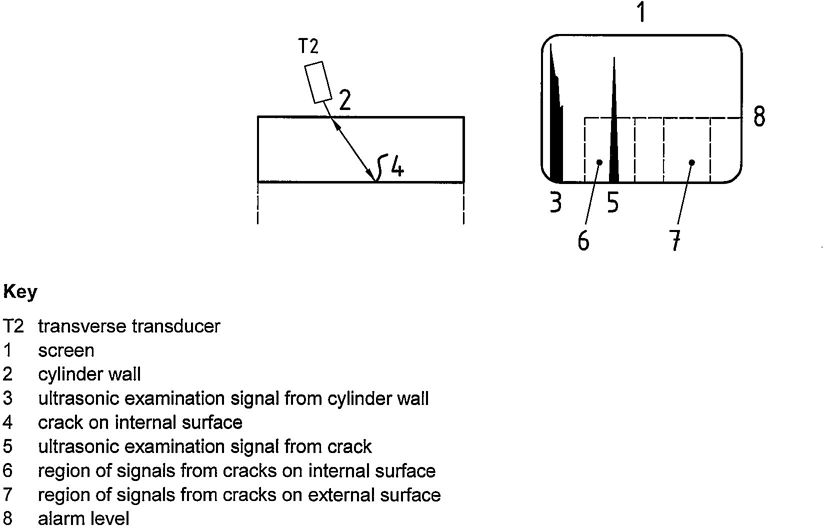
Figure 8—Detection of crack in transverse direction
14In addition to the required records as specified in 14.7, the following information shall be recorded.
If a valve or any other accessory is to be reintroduced into service, it shall be inspected and maintained to ensure that it will perform satisfactorily in service and meet the requirements of gas tightness from valve manufacturing standards, e.g. ISO 10297. An example of a suitable method is given in Annex F.
Any operation that could result in loss of wall thickness to below minimum guaranteed wall thickness shall be completed before the inspection and testing procedure (see Annex B).
When the cylinder is being prepared for final identification for future service, it shall be ensured that any residual gas in the container is compatible with the new gas service (See Clause 6 for depressurization requirements and ISO 11621).
The interior of each acceptable (passed) cylinder shall be thoroughly dried by a suitable method immediately after hydraulic pressure testing so there is no trace of free water (see 14.2.2 for maximum temperature values to be used, if applicable). The interior of the cylinder shall be inspected to ensure that it is dry and free from other contaminants.
Cylinders are sometimes repainted using paints that require stoving. Plastic coatings may also be reapplied. Paint and coating shall be applied so that all cylinder markings remain legible.
Aluminium-alloy cylinders are normally manufactured using precise heat treatment to obtain the final mechanical properties of the cylinders. Therefore the maximum temperature for any operation shall be limited.
In no case shall be temperature of the cylinder exceed that recommended by the manufacturer since overheating could change the mechanical properties of the cylinder.
Cylinders manufactured from heat-treatable aluminium alloys shall not be heated to temperatures exceeding 175°C unless the cylinder manufacturer recommends otherwise. Only responsible organizations that can properly control heat input and record time and temperature shall heat cylinders. The total cumulative time at temperatures between 110°C and 175°C shall be limited to the time recommended by the cylinder manufacturer. Cylinders heated in accordance with these provisions shall not require further testing.
15Unless otherwise recommended by the cylinder manufacturer, for cylinders manufactured from non-heat-treated alloys (e.g. AA5283), the maximum temperature shall not exceed 80 °C. For temperatures between 70 °C and 80 °C, the exposure time shall be limited to 30 min. If the heat exposure time exceeds 30 min at temperatures greater than or equal to 70 °C, or if at any time the temperature exceeds 80 °C, then agreement shall be obtained from the manufacturer regarding further use of the cylinder.
Before re-valving the cylinder, the thread type shall be identified. The appropriate valve shall be fitted to the cylinder using a suitable sealing material. An optimum torque necessary both to ensure a seal between the valve and the cylinder and to prevent over-stressing the neck shall be used as specified in ISO 13341.
The torque applied shall take into consideration the size and form of the threads, the material of the valve and the type of sealing material used according to the manufacturer's recommendations. Where the use of lubricants/sealing material is permitted, only those approved for the gas service shall be used, taking particular care for oxygen service (see ISO 11114-2).
The requirement shall apply only to cylinders for liquefied gases. However, it may be applied to any cylinder when there is doubt. The tare of the cylinders shall be obtained by weighing on a scale calibrated with traceability to national or international standards. The weigh scale shall be checked for accuracy on a daily basis. The capacity of the weighing scale shall be suitable for the tare of the appropriate cylinders.
The tare is the sum of the empty weight plus the mass of any coating (e.g. paint) used in service, the mass of the valve including dip tube where fitted, any fixed valve guard and the mass of all other parts that are permanently attached (e.g. by clamping or bolting) to the cylinder when presented for filling. If the tare of the cylinder differs from the stamped tare by more than the value shown in Table 1 and it is not due to damage, the original tare shall be cancelled and the correct tare shall be marked in a durable and legible fashion (see ISO 13769) after approval by a competent person. The empty weight shall not be altered.
| Cylinder water capacity, V l |
Maximum permissible deviation in tare g |
|---|---|
| 0,5≤ V <5,0 | ± 50 |
| 5,0≤ V ≤20 | ± 200 |
| V > 20 | ± 400 |
After satisfactory completion of the periodic inspections and tests, each cylinder shall be permanently marked according to the relevant standard or regulation, e.g. ISO 13769, with
The retester symbol is the symbol of the inspection body or test station. The retest date is the date of the present test, which shall be indicated by the year and month.
16These marks shall be in accordance with the relevant standard or regulation, e.g. ISO 13769.
In accordance with the relevant regulations and when regulations require, the next inspection and test date shall be shown by an appropriate method such as by a disc fitted between the valve and the cylinder indicating the date (year and month) of the next periodic inspection and/or tests. Annex G provides one example of a system for indicating retest dates; other systems are in use, and the same systems are used with different colours for the same year.
Before the cylinder is reintroduced into service, the intended contents shall be identified. This need not be part of the periodic inspection and test procedure. As an example, use ISO 7225 for labelling and ISO 32 for colour coding. If painting is required, care shall be exercised in accordance with 14.2.2. If a change of gas service is involved, care shall be taken to follow the requirements of ISO 11621.
A cylinder periodic inspection and test shall be recorded by test station personnel, and the following information shall be available for inspection:
Additionally, it shall be possible to obtain the following items of information from records, which need not necessarily be kept on a single file, but which will enable a particular cylinder to be uniquely traced:
The decision to reject a cylinder may be taken at any stage during the periodic inspection and test procedure. If it is impossible to recover a rejected cylinder, after notifying the owner, the testing station shall make the cylinder unserviceable for holding gas under pressure so that it is impossible for any part of the cylinder, especially the shoulder, to be reissued into service. In case of any disagreement, ensure that the legal implication of the contemplated action is fully understood.
Prior to taking any of the following actions, ensure that the cylinder is empty (see Clause 6).
The following methods may be employed:
The following information includes intervals as outlined in the United Nations Recommendations on the Transport of Dangerous Goods, Model Regulations, thirteenth edition. The most current edition should be consulted.
| Gas type | Examples | UN recommended interval years | |
|---|---|---|---|
| Compressed gases | Ar, N2, He | 10 | |
| H2 a | 10 | ||
| air, O2 | 10 | ||
| self-contained breathing air, O2 | b | ||
| gases for underwater breathing apparatus | b | ||
| COc, e | 5 | ||
| Liquefied gases | refrigerants, CO2 | 10 | |
| Corrosive gases | d | 5 | |
| Toxic gases that are non-corrosive | sulphuryl fluoride | 5 | |
| Very toxic gases that are non-corrosive | arsine (AsH3), phosphine (PH3) | 5 | |
| Gas mixtures | all mixtures | 5 or 10 years according to dangerous properties. Generally, mixtures that are toxic or corrosive have a 5-year interval, and other mixtures have a 10-year interval. |
|
| NOTE 1 These test periods may be used provided the dryness of the product and that of the filled cylinder are such that there is no free water. This condition shall be proven and documented within a quality system of the filler. If these conditions cannot be fulfilled, alternative or more frequent testing could be appropriate. NOTE 2 At all times certain requirements could necessitate a shorter time interval, e.g. the dew point of the gas, polymerization reactions and decomposition reactions, cylinder design specifications, change of gas service, etc. |
|||
| a Particular attention shall be paid to the tensile strength and surface condition of such cylinders. Cylinders not in conformance with the special hydrogen requirements shall be withdrawn from hydrogen service. See ISO 11621 for possible additional testing b Local regulations will specify the interval between periodic inspections and tests. c This product requires very dry gas. See ISO 11114-1:1997. d Corrosivity is with reference to human tissue (see ISO 13338) and NOT cylinder material. e The interval between periodic inspections and tests may be extended to 10 years for aluminium-alloy cylinders, when the alloy of the cylinder has been subjected to a stress corrosion test as specified in ISO 7866. |
|||
Gas cylinder defects can be physical, material or due to corrosion as a result of environmental or service conditions to which the cylinder has been subjected during its life.
This annex provides a convenient summary of most of the conditions identified in the text. The text describes the features for which the cylinder shall be inspected as well as the criteria applied to the features. The inspector shall be familiar with all the features as stated in the text that required inspection. This annex applies to all cylinders except those that have contained gases having special characteristics, which required modified controls.
Any defect in the form of a sharp notch may be removed by grinding, machining or other approved methods. After such a repair, the wall thickness shall be checked (See Clause 13), e.g. ultrasonically.
Evaluation of physical or material defects shall be in accordance with Table B.1.
Permanent attachments (e.g. foot rings or shrouds) shall be inspected and shall be suitable for their intended purposes.
The cylinder could be subjected to environmental conditions that could cause external corrosion of the metal.
Internal corrosion of the metal can also occur owing to service conditions.
There is difficulty in presenting definite rejection limits in tabular form for all sizes and types of cylinders and their service conditions. The limits of rejection are usually established following considerable field experience.
Extensive experience and judgment are required in evaluating whether cylinders that have corroded internally are safe and suitable for return to service. It is important that the surface of the metal is cleaned of corrosion products prior to the inspection of the cylinder.
20| Type of defect | Definition | Rejection limits in accordance with Clause 7a | Repair or render unserviceable |
|---|---|---|---|
| Bulge | Visible swelling of the cylinder | All cylinders with such a defect | Render unserviceable |
| Dent | A depression in the cylinder that has neither penetrated nor removed metal and is greater in depth than 1 % of the external diameter | When the depth of the dent exceeds 3% of the external diameter of the cylinder or when the diameter of the dent is less than 15 times its depth |
Render unserviceable Render unserviceable |
| Cut or gouge | A sharp impression where metal has been removed or redistributed whose depth exceeds 5% of the cylinder wall thickness (see Figure B.1) | When the depth of the cut or gouge exceeds 10% of the wall thickness or when the length exceeds 25% of the external diameter of the cylinder or when the wall thickness is less than the minimum guaranteed thickness |
Repair possibleb Repair possibleb Render unserviceable |
| Crack | A split or rift in the metal (see Figure B.2) | All cylinders with such defects | Render unserviceable |
| Fire damage | Excessive general or localized heating of a cylinder usually indicated by
|
All cylinders in categories a) and b) Cylinders in categories c) and d) may be acceptable after inspection and testing |
Render unserviceable Repair possible. In case of doubt, render unserviceable. |
| Plug or neck inserts | Additional inserts fitted in the cylinder neck, base or wall | All cylinders unless it can be clearly established that addition is part of approved design | Repair possible |
| Stamping | Marking by means of a metal punch | All cylinders with illegible, modified or incorrect markings | Render unserviceablec |
| Arc or torch burns | Partial melting of the cylinder, the addition of weld metal or the removal or metal by scarfing or cratering | All cylinders with such defects | Render unserviceable |
| Suspicious marks | Marks introduced other than by the cylinder manufacturing process and approved repair | All cylinders with such defects | Continued use possible after additional inspection |
| Some neck cracks (≤ 1 mm) may be repaired only in accordance with an agreed manufacturer's specification. | |||
| a When applying the rejection criteria, the conditions of use of the cylinders, the severity of the defect and safety factors in the design shall be taken into consideration. b Repair is possible provided that after repair by a suitable metal removal technique, the remaining wall thickness is at least equal to the minimum guaranteed wall thickness. c If it can be clearly established that the cylinder fully complies with the appropriate specifications, altered operational and modified markings may be acceptable and inadequate markings may be corrected, provided there is no possibility of confusion. |
|||
The types of corrosion may in general be classified as in Table B.2.
| Type of corrosion | Definition | Rejection limits in accordance with Clause 7a | Repair or render unserviceable |
|---|---|---|---|
| General corrosion | Loss of wall thickness over an area of more than 20 % of either the interior or exterior total surface area of the cylinder (See Figure B.3) | If the original surface of the metal is no longer recognizable or If the depth of penetration exceeds 10% of the original thickness of wall or If the wall thickness is less than minimum guaranteed wall thicknessb |
Repair possible Repair possiblec Render unserviceable |
| Local corrosion | Loss of wall thickness over an area of less than 20% of either the interior or exterior total surface area of the cylinder, except for the other types of local corrosion described below | If the depth of penetration exceeds 20% of the original thickness of the cylinder wall or if the wall thickness is less than minimum guaranteed thicknessb |
Repair possibled Render unserviceable |
| Chain, pitting or line corrosion | Corrosion forming a narrow longitudinal or circumferential line or strip, or isolated craters or pits that are almost connected (see Figure B.4) | If a total length of corrosion in any direction exceeds the diameter of the cylinder and the depth exceeds 10 % of the original wall thickness or if the wall thickness is less than minimum guaranteed thicknessb |
Repair possibled Render unserviceable |
| Isolated pits | Corrosion forming isolated craters, without significant alignment (see Figure B.5) | If the diameter of the pits is greater than 5 mm, refer to the “local corrosion” row If the diameter of the pits is less than 5 mm, the cylinder should be assessed as carefully as possible in order to check the remaining thickness of the wall or base is adequate for the intended use of the cylinder |
See “local corrosion” row Repair possible |
| a If the bottom of the defect cannot be seen and if its extent cannot be determined using appropriate equipment, the cylinder shall be scrapped. b If corrosion has reached limits of depth or extent, the remaining wall thickness should be checked with an ultrasonic device. The wall thickness may be less than the minimum guaranteed wall thickness, e.g. small (depth and extent) isolated pits (See Figure B.5), where authorized by the relevant regulations taking into consideration the severity of the defect and safety factors. c After repair, a cylinder shall follow requirements in Clauses 7, 8 and 9. d Repair is possible provided that after repair by a suitable metal removal technique, the remaining wall thickness is at least equal to the minimum guaranteed wall thickness. |
|||
Reject cracks in accordance with Table B.1.
Some cylinders with taper threads can be subject to neck cracks. After cleaning in a suitable way, cracks can be detected by visual inspection. Figure B.8 shows the location and likely propagation of such cracks. Neck cracks should not be confused with tap markings, which normally are visible parallel lines. Figure B.7 shows tap markings.
Some cylinders with parallel threads can be subject to shoulder cracks. They can start from folds in the internal shoulder area and propagate into the threaded area or shoulder of the cylinder. Hence, this lower threaded area of the neck shall be very carefully inspected. Figure B.8 shows exactly where shoulder cracks start and how they propagate.
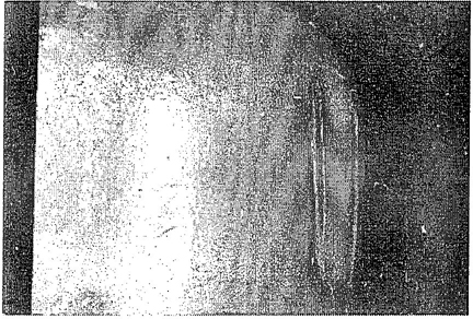
Figure B.1—Cut or gouge
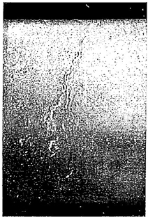
Figure B.2—Crack
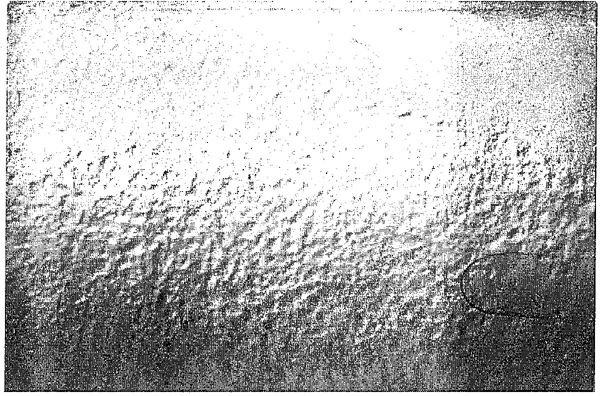
Figure B.3—General corrosion
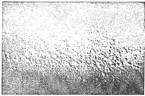
Figure B.4—Line corrosion
23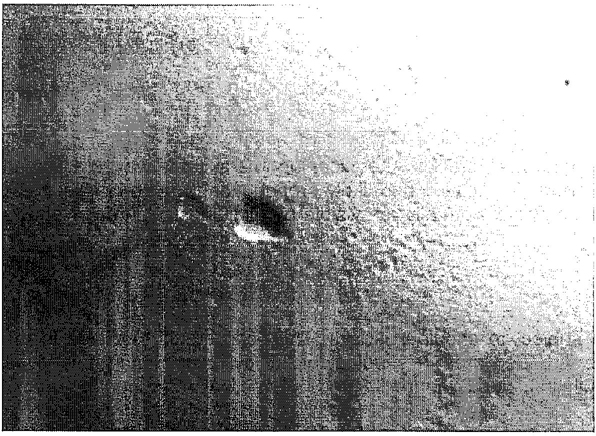
Figure B.5—Isolated pits
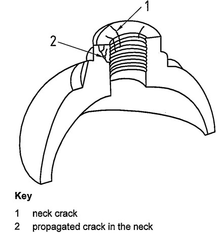
Figure B.6—Neck cracks
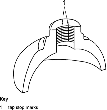
Figure B.7—Tap stop marks
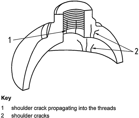
Figure B.8—Shoulder cracks
24The following procedures shall be carried out by only by personnel competent in this field. In view of the potential hazards in cylinders, this operation can lead to injury from stored energy release, fire and toxic hazards; hence, personnel shall take such precautions as deemed necessary for the work to be performed. When the gas, if any, has been released and the pressure within the cylinder reduced to atmospheric pressure, and, in the case of liquefied gases, when there is no frost or dew on the outside of the cylinder, the valve may be removed after an additional check is made to establish that there is free passage through the valve.
As indicated in Clause 6, a systematic check shall be made to establish that the passage through the valve is unobstructed. The method adopted shall be a recognized procedure such as one of the following or one that provides equivalent safeguards.
— Introduce a gas, non-reactive to the gas stored in the cylinder, at a pressure up to 5 bar and check its discharge.
— Use the device shown in Figure C.1 to hand pump air into the cylinder.
— For a cylinder of liquefied gas, first check to establish that the total weight of the cylinder is the same as the tare stamped on the cylinder. If there is a positive difference, the cylinder could contain either liquefied gas under pressure or contaminants. Lack of a positive difference does not rule out the presence of a gas under pressure.
— For a valve incorporating a residual pressure device (e. g. see ISO 15996), the operator shall use a specific adapter to release the remaining pressure and verify the absence of pressure using one of the methods described previously.
Only when it has been established that there is no obstruction to gas flow in the cylinder valve, may the valve be removed. Personal protection during de-valving shall be assessed.
The following methods are applicable for cylinders of non-toxic, non-flammable and non-chlorofluorocarbon (non-CFC) gases. Appropriate safety precautions should be taken to ensure that no hazard results from the uncontrolled discharge of any residual gas. When a cylinder is found to have an obstructed gas passage in the valve, the cylinder shall be set aside and handled by specially trained personnel in this task by one of the following methods.
— Saw or drill the valve body until interception is made with the gas passage between the valve body stem and valve spindle seat. The operation shall be properly cooled particularly when handling oxidizing gases.
— Loosen or pierce the pressure relief device in a controlled manner.
25Cylinders of toxic, flammable, air-reactive, water-reactive, oxidizing, and CFC gases shall be handled by one of the following methods. After release, containment and subsequent disposal shall be carried out safety and without impact to the environment.
— Partially unscrew the valve within a glanded cap, secured and joined to the cylinder and vented to a safe discharge. The principles of a suitable device are illustrated in Figure C.2. This procedure shall be performed in a controlled manner in such a way as to avoid personal injury.
— Mechanically remove the valve in an enclosed, automated device that will contain the release of gas and release of energy.
— Place the cylinder in a container suitable to contain the release of gas and release of energy, and crush or puncture the cylinder to release the material and pressure.
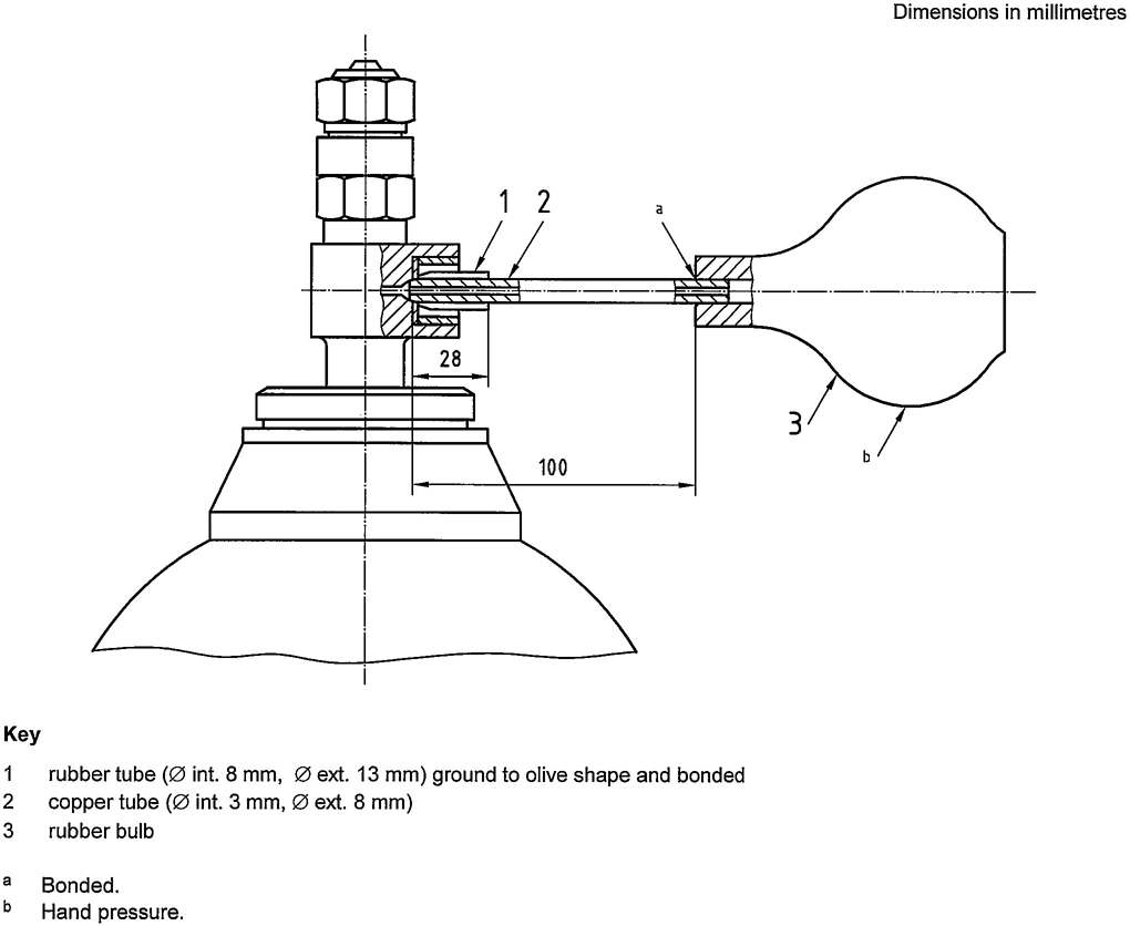
Figure C.1 — Typical device for detecting an obstructed cylinder valve
26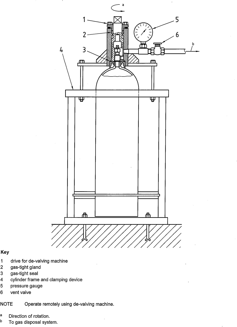
Figure C.2 — Typical device for the removal of a damaged gas cylinder valve
27WARNING — Ensure the chemical cleaning product is in accordance with the recommendations of the cylinder manufacturer; otherwise serious damage may occur. To ensure gas compatibility, the cleansing agent shall be completely removed or the final cleansing operation shall be compatible with the intended gas service.
Aluminium-alloy gas cylinders in normal service can accumulate internal contamination, which may detrimentally affect use. If internal contamination is detected, the source should be investigated. The following procedures are examples for cleaning the interior of aluminium-alloy gas cylinders.
| Contamination | Cleaning method |
|---|---|
| Oil and grease | Degrease with suitable solvent |
| Odour | Rinse with solution of sodium bicarbonate, the rinse with a 5 % solution of acetic acid |
| Corrosion | Tumble with aluminium-oxide chips, pellets or glass beads Blasting (e.g. with glass beads). See Clause 8. |
For the removal of moisture and lose particles and after each cleaning method, rinse with tap water, then rinse with distilled or de-ionized water, then steam clean and dry.
NOTE Ensure all traces of cleaning agent have been removed. For temperature limits see 14.2.2
Examples of methods for cleaning external surfaces are
— soap and water,
— solvent wipe, and
— scouring pad and scrubbing.
28This annex gives details of the three methods for determining the volumetric expansion of aluminium-alloy gas cylinders:
— two water jacket methods (preferred method); and
— the non-water jacket method.
The water jacket volumetric expansion test shall be carried out on equipment with a leveling burette, with a fixed burette or with a weigh scale that contains water.
The following general requirements shall apply to all three methods of test.
— Hydraulic test pressure pipelines shall be capable of withstanding a pressure 1,5 times the maximum test pressure of any cylinder that may be tested.
— The glass burette at the maximum recorded pressure shall be of sufficient length to contain the full volumetric expansion of the cylinder and shall have bores of uniform diameter such that the expansion can be read to an accuracy of ± 1 % or 0,1 ml, whichever is the greater.
— Weigh scales shall be capable of providing total expansion measurements to an accuracy of ± 1 % or 0,1 g, whichever is greater.
— Pressure gauges shall be of the industrial Class 1 with a scale appropriate to the test pressure. They shall be calibrated at regular intervals and in any case not less than once per month.
— A suitable system control device shall be employed to ensure that no cylinder is subjected to a pressure in excess of its test pressure  or 10 bar, whichever is less.
— Pipework should utilize long bends in preference to elbow fittings, and pressure pipes should be as short as possible. Flexible tubing shall be capable of withstanding 1,5 times the maximum test pressure in the equipment.
— All joints shall be leak tight.
— When installing equipment, care shall be taken to avoid trapping of air in the system.
This method of test necessitates enclosing the water filled cylinder in a jacket also filled with water. The total and any permanent volumetric expansion of the cylinders are measured as to the amount of water displaced by the expansion of the cylinder when under pressure and after the pressure is released. The permanent expansion is calculated as a percentage of the total expansion. The water jacket shall be fitted with a safety device capable of releasing the energy from any cylinder that could burst at test pressure.
29An air bleed valve should be fitted to the highest point of the jacket.
Two methods for performing this test are described in E.3.2 and E.3.3. Other equivalent methods are acceptable provided they are capable of measuring the total and, if any, the permanent volumetric expansion of the cylinder.
The equipment should be installed as shown in Figure E.1.
The procedure shall be as follows.
 , or 10 bar, whichever is less) is reached. Close hydraulic pressure line valve and stop pumping.
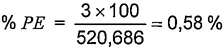
The equipment should be installed as shown in Figure E.2. The procedure for this method of test is similar to that described in E.3.2 except that the burette is fixed.
— Adjust water level to a datum. Apply pressure until test pressure is reached and record the burette reading. The reading above the datum is the total expansion, and shall be recorded on the test certificate.
— Check that the permanent expansion does not exceed the percentage given in the design specification, as determined by the following equation:
This method consists of measuring the amount of water passed into the cylinder under proof pressure, and on release of this pressure, measuring the water returned to the burette. It is necessary to allow for the compressibility of water and the volume of the cylinder under test to obtain true volumetric expansion. No fall in pressure under this test is permitted.
The water used should be clean and free of dissolved air. Any leakage from the system or the presence of free or dissolved air will result in false readings.
The equipment should be installed as shown in Figure E.3, which illustrates diagrammatically the different parts of the apparatus. The water supply pipe should be connected to an overhead tank as shown, or to some other supply giving a sufficient head of water.
The apparatus shall be arranged such that all air can be removed and that accurate readings can be determined of the volume of water required to pressurize the filled cylinder and of the volume expelled from the cylinder when depressurized. In the case of larger cylinders, it may be necessary to augment the glass tube with metal tubes arranged in the manifold.
If a single acting hydraulic pump is used, care shall be taken to ensure that the piston is in the “back” position when water levels are noted.
The test method shall be as follows.
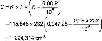
The formula used for the calculation of water shall be as follows:
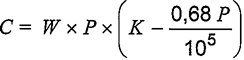
where
C is the compressibility, in cm3;
W is the mass of water, in kg;
P is the pressure, in bar;
K is the factor for individual temperature as listed in Table E.1.
| Temperature °C | K |
|---|---|
| 6 | 0,049 15 |
| 7 | 0,048 86 |
| 8 | 0,048 60 |
| 9 | 0,048 34 |
| 10 | 0,048 12 |
| 11 | 0,047 92 |
| 12 | 0,047 75 |
| 13 | 0,047 59 |
| 14 | 0,047 42 |
| 15 | 0,047 25 |
| 16 | 0,047 10 |
| 17 | 0,046 95 |
| 18 | 0,046 80 |
| 19 | 0,046 68 |
| 20 | 0,046 54 |
| 21 | 0,046 43 |
| 22 | 0,046 33 |
| 23 | 0,046 23 |
| 24 | 0,046 13 |
| 25 | 0,046 04 |
| 26 | 0,045 94 |
In the following example calculation, allowance for pipe stretch has been neglected.
EXAMPLE
| Test pressure: | 232 bar |
| Mass of water in cylinder at zero gauge pressure: | 113.8kg |
| Temperature of water: | 15 °C |
| Water forced into cylinder to raise pressure to 232 bar: | 1745 cm3(or 1,745 kg) |
| Total mass of water (m) in cylinder to at 232 bar: | 113,8+1,745=115,545 kg |
| Water expelled from cylinder to depressurize: | 1742 cm3 |
| Permanent expansion(PE): | 1745-1742=3 cm3 |
| From Table E.1, K factor for 15 °C | 0,04725 |
 |
|
| Total volumetric expansion (TE): | 1 745-1224,31=520,686 cm3 |
 |
|
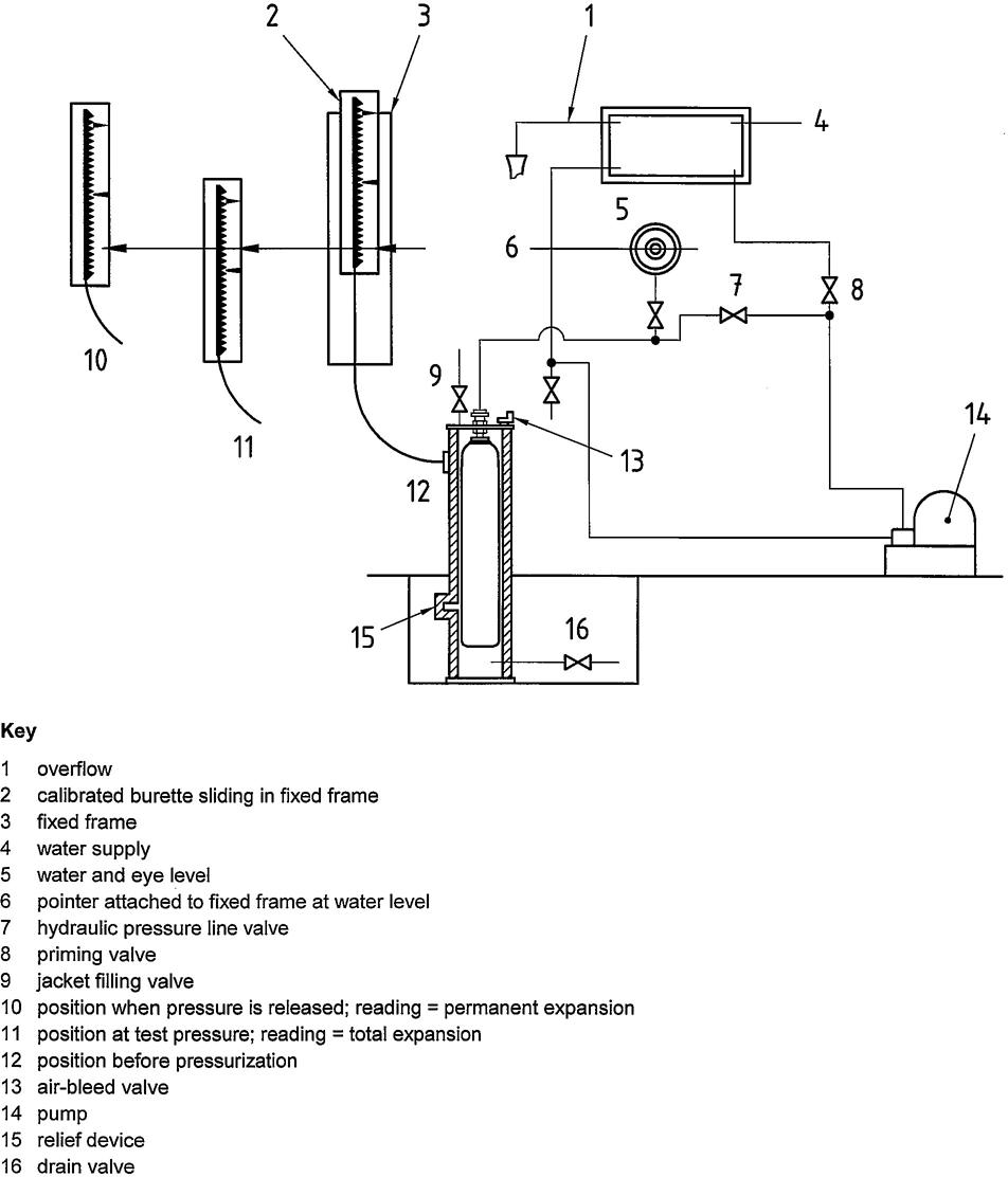
Figure E.1 — Water jacket volumetric expansion test (levelling burette method)
34
Figure E.2 — Water jacket volumetric expansion test (fixed burette method)
35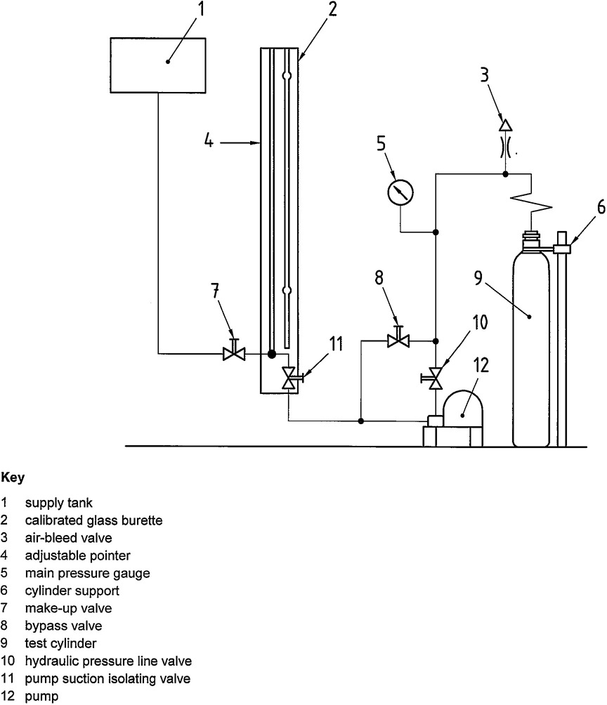
Figure E.3 —Non-water jacket volumetric expansion test — diagrammatic layout of cylinder testing apparatus
36All threads shall be checked to ensure the thread diameters, form, length and taper are satisfactory.
If threads show signs for distortion, deformation or burring, these faults shall be rectified. Excessive thread damage or serious deformation of the valve body, hand wheel, spindle or other components is cause for replacement.
Maintenance of the valve shall include general cleaning together with replacement of elastomers and worn or damaged components, packing and safety devices, where necessary.
Where the use of lubricants/elastomers is permitted, only those approved for the gas service shall be used, particularly for oxidizing gas service.
After the valve has been reassembled, it shall be checked for correct operation and shall undergo internal and external leak checks at intended operating pressure (for example, see ISO 10297 and ISO 14246). This may be done prior to the valve being refitted to the cylinder or during and after the first gas charge subsequent to the inspection and test of the cylinder.
For additional information, refer to EN 14189.
37NOTE Systems other than the one specified in Table G.1 are in use, and the same system is used with different colours.
| Year | Colour | Shape |
|---|---|---|
| 2000 | Aluminium | Circle |
| 2001 | Red | Hexagon |
| 2002 | Blue | Hexagon |
| 2003 | Yellow | Hexagon |
| 2004 | Green | Hexagon |
| 2005 | Black | Hexagon |
| 2006 | Aluminium | Hexagon |
| 2007 | Red | Square |
| 2008 | Blue | Square |
| 2009 | Yellow | Square |
| 2010 | Green | Square |
| 2011 | Black | Square |
| 2012 | Aluminium | Square |
| 2013 | Red | Circle |
| 2014 | Blue | Circle |
| 2015 | Yellow | Circle |
| 2016 | Green | Circle |
| 2017 | Black | Circle |
| 2018a | Aluminium | Circle |
| 2019 | Red | Hexagon |
| 2020 | Blue | Hexagon |
| 2021 | Yellow | Hexagon |
| 2022 | Green | Hexagon |
| 2023 | Black | Hexagon |
| 2024 | Aluminium | Hexagon |
| a The sequence of colour and shape of test date rings is to be repeated on an 18-year cycle. Hence, 2018 is a repeat of 2000. | ||
ICS 23.020.30
price based on 39 pages