In order to promote public education and public safety, equal justice for all, a better informed citizenry, the rule of law, world trade and world peace, this legal document is hereby made available on a noncommercial basis, as it is the right of all humans to know and speak the laws that govern them.
IEEE Std 1202-1991
Sponsor
Power Systems Engineering Committee
of the
Industry Applications Society
Approved March 21, 1991
IEEE Standards Board
Abstract: A test protocol and the performance criteria to determine the flame propagation tendency of cables in a vertical cable tray. It applies to single insulated and multiconductor cables is established. The test consists of exposing cable samples to a theoretical 20 kW (70 000 Btu/hr) flaming ignition source for a 20 min duration. The test facility, test sample requirements, test procedure, and evaluation of results are covered.
Keywords: cable flame testing, cable tray, flame test facility, flame testing of cables
The Institute of Electrical and Electronics Engineers, Inc.
345 East 47th street, New York, NY 10017-2394, USA
© 1991 by the Institute of Electrical and Electronics Engineers, Inc.
All rights reserved. Published 1991
Printed in the United States of America
ISBN 1-55937-122-6
No part of this publication may be reproduced in any form, in an electronic retrieval system or otherwise, without the prior written permission of the publisher.
iiIEEE Standards documents are developed within the Technical Committees of the IEEE Societies and the Standards Coordinating Committees of the IEEE Standards Board. Members of the committees serve voluntarily and without compensation. They are not necessarily members of the Institute. The standards developed within IEEE represent a consensus of the broad expertise on the subject within the Institute as well as those activities outside of IEEE which have expressed an interest in participating in the development of the standard.
Use of an IEEE Standard is wholly voluntary. The existence of an IEEE Standard does not imply that there are no other ways to produce, test, measure, purchase, market, or provide other goods and services related to the scope of the IEEE Standard. Furthermore, the viewpoint expressed at the time a standard is approved and issued is subject to change brought about through developments in the state of the art and comments received from users of the standard. Every IEEE Standard is subjected to review at least every five years for revision or reaffirmation. When a document is more than five years old, and has not been reaffirmed, it is reasonable to conclude that its contents, although still of some value, do not wholly reflect the present state of the art. Users are cautioned to check to determine that they have the latest edition of any IEEE Standard.
Comments for revision of IEEE Standards are welcome from any interested party, regardless of membership affiliation with IEEE. Suggestions for changes in documents should be in the form of a proposed change of text, together with appropriate supporting comments.
Interpretations: Occasionally questions may arise regarding the meaning of portions of standards as they relate to specific applications. When the need for interpretations is brought to the attention of IEEE, the Institute will initiate action to prepare appropriate responses. Since IEEE Standards represent a consensus of all concerned interests, it is important to ensure that any interpretation has also received the concurrence of a balance of interests. For this reason IEEE and the members of its technical committees are not able to provide an instant response to interpretation requests except in those cases where the matter has previously received formal consideration.
Comments on standards and requests for interpretations should be addressed to:
Secretary, IEEE Standards Board
445 Hoes Lane
P.O. Box 1331
Piscataway, NJ 08855-1331
USA
| IEEE Standards documents are adopted by the Institute of Electrical and Electronics Engineers without regard to whether their adoption may involve patents on articles, materials, or processes. Such adoption does not assume any liability to any patent owner, nor does it assume any obligation whatever to parties adopting the standards documents. |
(This Foreword is not a part of IEEE Std 1202-1991, IEEE Standard for Flame Testing of Cables for Use in Cable Tray in Industrial and Commercial Occupancies.)
This standard was prepared by the Tray Cable Flame Test Working Group of the Power Equipment Subcommittee of the Power Systems Engineering Committee of the IEEE Industry Applications Society. Members of this Working Group represent a cross-section of the affected parties including industrial and commercial users, material suppliers, cable manufacturers, consulting engineers, testing laboratories, and insurance companies.
The Insulated Conductors Committee of the IEEE Power Engineering Society also reviewed and endorsed this standard.
At the time this standard was completed, the Tray Cable Flame Test Working Group had the following membership:
James M. Daly, Chair
M. Bayer
D. N. Bishop
M. Bourassa
G. R. J. Bracey
K. R. Bullock
T. Burke
J. Cancelosi
P. L. Cinquemani
J. D. Cospolitch
R. P. Derrick
G. L. Dorna
R. L. Doughty
A. Fine
M. V. Glenn
D. L. Goldberg
T. Guida
C. Hafer
A. P. Haggerty
W. Hattori
E. Hesla
Dr. M. M. Hirschler
C. Moss Hodnett
E. G. Hoffman
S. Kaufman
G. Klein
F. E. LaGase
R. Lageman
R. C. Lennig
Dr. T. H. Ling
P. Lorigan
Dr. M. E. Lowell
V. B. Mascarenhas
L. B. McClung
R. G. Medley
L. D. Monaghan
S. Paniri
C. A. Petrizzo
J. R. Pfafflin
J. J. Pickering
A. Pierce
P. Pollak
C. Prasso
L. Przybyla
M. H. Ramsey
L. F. Saunders
A. Scolnik
N. Stamp
D. Stonkus
G. Straniero
R. Thrash
A. C. Tingley
N. W. Todd
C. Tripp
H. Willis
D. W. Zipse
At the time this standard was balloted, the P1202 Balloting Committee of the IAS Power Systems Engineering Committee had the following membership:
G. R. J. Bracey
J. M. Daly
R. L. Doughty
D. L. Goldberg
A. P. Haggerty
E. Hesla
W. J. Kelly
D. D. Koval
R. H. McFadden
R. G. Medley
C. B. Pinheiro
M. D. Robinson
L. F. Saunders
B. W. Whittington
D. W. Zipse
When the IEEE Standards Board approved this standard on March 21, 1991, it had the following membership:
Marco W. Migliaro, Chair
Donald C. Loughry, Vice Chair
Andrew G. Salem, Secretary
Dennis Bodson
Paul L. Borrill
Clyde Camp
James M. Daly
Donald C. Fleckenstein
Jay Forster*
David F. Franklin
Ingrid Fromm
Thomas L. Hannan
Donald N. Heirman
Kenneth D. Hendrix
John W. Horch
Ben C. Johnson
Ivor N. Knight
Joseph L. Koepfinger*
Irving Kolodny
Michael A. Lawler
John E. May, Jr.
Lawrence V. McCall
Donald T. Michael*
Stig L. Nilsson
John L. Rankine
Ronald H. Reimer
Gary S. Robinson
Terrance R. Whittemore
*Member Emeritus
v| CLAUSE | PAGE | ||
|---|---|---|---|
| 1. | Introduction | 1 | |
| 1.1 | Scope | 1 | |
| 1.2 | Purpose | 1 | |
| 1.3 | Applications | 1 | |
| 1.4 | Disclaimer | 1 | |
| 1.5 | Units of Measurement | 2 | |
| 1.6 | Test Precautions | 2 | |
| 2. | Definitions | 2 | |
| 3. | References | 2 | |
| 4. | Flame Test Facility | 2 | |
| 4.1 | Enclosure | 2 | |
| 4.2 | Exhaust Duct | 4 | |
| 4.3 | Air Movement Within Enclosure | 5 | |
| 4.4 | Cable Tray | 5 | |
| 4.5 | Burner | 5 | |
| 4.6 | Flowmeters | 6 | |
| 4.7 | Air | 6 | |
| 4.8 | Propane | 6 | |
| 5. | Test Sample Requirements | 7 | |
| 5.1 | Cable Samples | 7 | |
| 5.2 | Tests Required | 7 | |
| 6. | Flame Test Procedure | 7 | |
| 6.1 | Cable Mounting | 7 | |
| 6.2 | Test Procedure | 8 | |
| 7. | Test Evaluation | 10 | |
| 7.1 | Evaluation of Damage | 10 | |
| 7.2 | Performance Criteria | 10 | |
| 7.3 | Test Report | 10 | |
IEEE Standard for Flame Testing of Cables for Use in Cable Tray in Industrial and Commercial Occupancies
This standard provides a protocol for exposing cable samples to a theoretical 20 kW (70 000 Btu/hr) flaming ignition source for a 20 min test duration. The test determines the flame propagation tendency of single conductor and multiconductor cables intended for use in cable trays in industrial and commercial occupancies.
The purpose of this standard is to establish a test protocol and performance criteria to determine the flame propagation tendency of cables in a vertical cable tray.
This standard shall apply to single insulated conductor and multiconductor cables that are permitted to be used in cable tray installed either horizontally or vertically in installations covered by ANSI/NFPA 70-1990, National Electrical Code (NEC) [2].1 This standard is not intended to apply to installations that are not covered by the NEC.
The results obtained using this test do not imply that cables of similar cable construction will necessarily perform the same way in other cable arrangements, other cable tray configurations, or other environments.
1 The numbers in brackets correspond to those in Section 3. ANSI publications are available from the Sales Department of the American National Standards Institute, 11 West 42nd Street, 13th Floor, New York, NY 10018. NFPA publications are available from Publication Sales, National Fire Protection Association, 1 Batterymarch Park, P.O. Box 9101, Quincy, MA 02269-9101.
1When a value for a measurement is followed by a value in other units in parentheses, the second value may be only approximate. The first stated value shall be the requirement.
Fire testing of products and materials is inherently hazardous. Adequate safeguards for personnel and property shall be employed while conducting these tests.
cable construction: Cable construction shall include both single insulated conductors and multiconductor cables.
sample: The cable type and construction to be tested.
specimen: The individual length of cable or cable bundle to be placed in the cable tray for testing.
[1] ANSI/ASTM D1835-1987, Specification for Liquefied Petroleum (LP) Gases.2
[2] ANSI/NFPA 70-1990, National Electrical Code.
[3] CAN/CSGB-3.14-M1988 (Grade 1), Liquified Petroleum Gas (Propane), Canadian General Standards Board.3
[4] CSA Standard C22.1–1990, Canadian Electrical Code, Part I.4
[5] CSA Standard C22.2, No. 126-M1984, Cable-troughs and Fittings.
[6] NEMA VE 1-1984, Metallic Cable Tray Systems.5
[7] Crocker, S. Piping Handbook, New York: McGraw-Hill, 1945.
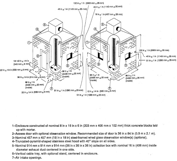
The enclosure in which the sample is tested shall be as shown in Fig 1.
2ANSI publications are available from the Sales Department of the American National Standards Institute, 11 West 42nd Street, 13th Floor, New York, NY 10018. ASTM publications are available from the Sales Department of the American Society for Testing Materials, 1916 Race Street, Philadelphia, PA 19103.
3Canadian General Standards are available from the Canadian General Standards Board, 11 Laurier, Phase 3, 9C1 Place du Portage, Hull, Quebec, Canada K1A 1G6.
4CSA publications are available from the Canadian Standards Association, 178 Rexdale Boulevard, Rexdale, Ontario, Canada M9W 1R3.
5NEMA publications are available from the National Electrical Manufacturers Association, 2101 L Street, N.W., Washington, DC 20037.
Figure 1—Cable Test Enclosure
The enclosure shown in Fig 1 is recommended for new construction. Other enclosure sizes such as 8 ft × 8 ft × 8 ft (2.4m × 2.4m × 2.4m) or the 3m cube shall be permitted to be used provided that the internal volume of the enclosure, exclusive of the pyramid hood, shall not be less than 14.5 m3 (512 ft3) nor greater than 36 m3 (1272 ft3), the floor area shall not be less than 6 m2 (64 ft2) nor greater than 9 m2 (97 ft2), and the maximum air movement within the enclosure complies with 4.3.
In the event of a dispute, the results of tests conducted in an enclosure sized as shown in Fig 1 shall be final.
3The walls of the enclosure shall have a maximum conductive heat flux loss of 6.8 W/(m2K) (30 Btu/h-ft2) based upon an inside wall temperature of 38 °C (100 °F) and an outside air temperature of 24 °C (75 °F). The interior surface of the walls shall be painted flat black. Any materials of construction that meet the above requirements are acceptable. Two examples of acceptable construction materials are 6 in (152 mm) thick concrete blocks or ½ in (13 mm) gypsum board with 3–½ in (89 mm) of standard fiberglass insulation with an R value of 11.
Windows shall be permitted in the walls and door for observation of the fire test; the total surface area of the windows shall not exceed 1.86 m2 (20 ft2). Exercise caution in selecting the materials and construction to withstand the open flame within the test enclosure and duct.
Air intakes shall be provided at the base of two opposite walls. The total cross-sectional area of the air intakes shall be 1.45 m2 ± 0.03 m2 (2250 in2 ± 50 in2), and the intake areas shall be divided approximately equal. Fig 1 shows dimensions for the air intakes installed in walls with and without an access door. Air intakes shall not be permitted in either of the other two walls.
The enclosure shall contain a door that permits access. The door shall have an overall conductive heat flux loss no greater than 6.8 W/(m2K) (30 Btu/h-ft2). The door shall be permitted to be located in any of the four walls. The sides and top of the door shall be adequately sealed to prevent drafts. The bottom of the door shall also be sealed to prevent drafts if it is located in a wall containing an air intake.
A hood, formed as shown in Fig 1, shall be located on top of the enclosure walls. The area between the hood and the walls shall be sealed. The hood shall have an overall conductive heat flux loss no greater than that of the walls.
A 914 mm × 914 mm × 914 mm (36 in × 36 in × 36 in) stainless steel collection box shall be located on top of the exhaust hood as shown in Fig 1.
The exhaust duct connected to the collection box on top of the hood shall be a 16 in (406 mm) nominal inside diameter pipe installed horizontally.
A variable-speed exhaust fan shall be located at the exhaust end of the duct. The exhaust duct shall be provided with instruments to measure gas velocity and temperature. A bidirectional probe or an equivalent measuring system shall be used to measure pressure in the duct. The probe shall be located in the exhaust duct at least 4.6m (15 ft) but not more than 13.7m (45 ft) from the center line of the collection box. The minimum length between any bend and the probe shall be at least 10 times the duct's inside diameter. The probe, shown in Fig 2, shall consist of a stainless steel cylinder 44 mm (1.75 in) long and 22 mm (0.875 in) outside diameter with a solid diaphragm in the center. The pressure taps on either side of the diaphragm support the probe. The axis of the probe shall be along the center line of the duct. The taps shall be connected to a pressure transducer that shall be able to resolve pressure differences of 0.25 Pa (0.001 in of water). A bare bead, high temperature Type K thermocouple, 0.51 mm (20 mils) in diameter, shall be located near the bidirectional probe.
4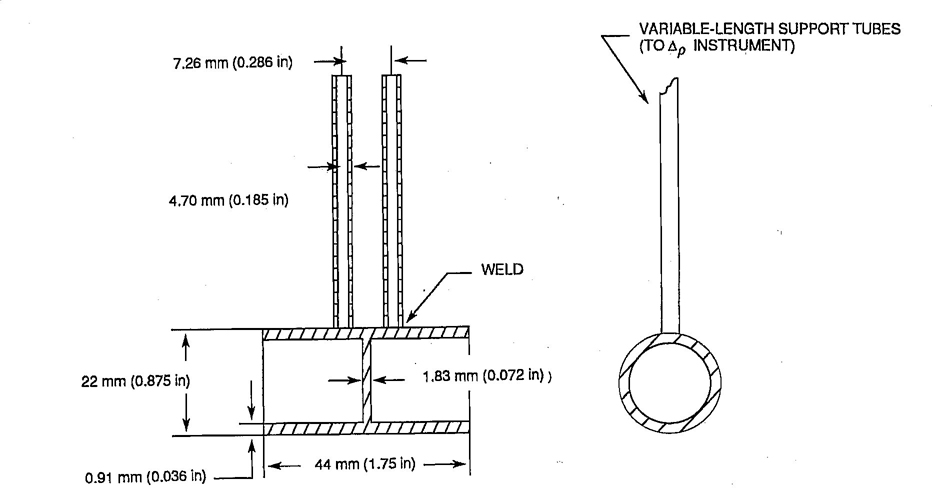
Figure 2—Bidirectional Probe
The maximum air movement within the enclosure, with only the intake and exhaust openings open, the exhaust fan on, if applicable, and the burner off, shall not exceed 1 m/s (3.3 ft/s), as measured by a vane-type anemometer in the following areas:
A steel ladder cable tray, as shown in Fig 3, shall be used. The cable tray shall comply with NEMA VE 1-1984[6] or CSA Standard C22.2, No. 126-M1984[5]. The rungs shall be attached to the inside of the side channels.
The tray shall be arranged so the burner flame will impinge on the cable midway between rungs.
The burner shall be a 254 mm (10 in) strip- or ribbon-type propane gas burner with an air/gas venturi mixer.
NOTE — A burner (catalog number 10 L 11-55) and venturi mixer (catalog number 14-18), which can be used to comply with the information contained in 4.5 are available from the American Gas Furnace Company, Inc., 140 Spring Street, Elizabeth, NJ 07207.
The burner shall be mounted on a stand and placed 20° ± 2° from the horizontal with the burner ports up (see Fig 3). The top of the burner shall be located 305 mm ± 25 mm (12 in ± 1 in) above the base of the cable tray and parallel to the cable tray rungs.
A guide shall be attached to the burner or stand so that the leading edge of the burner face can be accurately placed 76 mm ± 5 mm (3 in ± 0.2 in) horizontally from the nearest surface of the cables.
5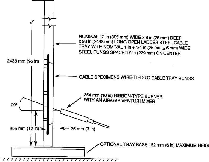
Figure 3—Cable Tray, Specimen, and Burner Details
A flowmeter shall be located in the propane line and in the air line feeding the burner to measure the flow rates of these gases during the test. Measurements shall be accurate within 3%. A mass flow controller with an output that can be recorded shall be permitted to be used.
The air supplied to the burner shall be compressed air, either bottled or supplied through a compressed air system. The air supply shall be filtered, when necessary, to eliminate contaminants that could effect the test results.
The temperature of the air shall be 25 °C ±5° (77 °F ± 9°). The dew point of the air shall not be greater than 0 °C (32 °F).
The propane gas supplied to the burner shall be equivalent to propane HD-5 as specified in ANSI/ASTM D1835-1987 [1] or CAN/CSGB-3.14-M1988 (Grade 1) [3]. It shall have a heat equivalent of approximately 46.4 MJ/kg (20 k Btu/lb) (85.0 MJ/m3 at 20 °C, 101 kPa).
The temperature of the propane gas shall be 25 °C ± 5° (77 °F ± 9°).
6Unless otherwise specified by the user, recognized testing laboratory, or the inspection authority, the minimum size construction and the cable construction having the highest weight ratio of nonmetallic material to metallic material in each product line shall be tested to qualify a product line employing identical materials. The weight ratio shall be calculated using the nominal weight for conductors and the nominal thicknesses for all other components. The quantity of nonmetallic and metallic materials within a product line shall be permitted to vary depending upon the conductor size and the number of conductors. Addition or deletion of a cable component or a change in material(s) shall constitute a new product line, except that deletion of fillers or a strand separator shall not constitute a new product line.
The minimum size construction shall be selected as follows:
Each product line shall be subjected to four flame tests—two on the minimum conductor size and two on the highest weight ratio construction. When the minimum conductor size and the highest weight ratio is the same cable construction, only two flame tests shall be required.
The length of each cable specimen or each cable bundle shall be 2.4 m ± 0.1 m (8 ft ± 0.33 ft). Depending upon the outside diameter of the individual cable, the test specimen shall be either an individual length or a bundle of individual lengths. The specimens or specimen bundles shall be centered between the side rails in a single layer. The lower end of each specimen or specimen bundle shall be located not more than 100 mm (4 in) above the bottom end of the cable tray. Each specimen or specimen bundle shall be separately attached to each rung of the cable tray using one wrap of a copper or steel wire tie not larger than 2.08 mm2 (14 AWG).
For cables smaller in diameter than 13 mm (0.51 in), the specimens shall be grouped into untwisted bundles (nominally circular) as specified in Table 1. The bundles shall be spaced one-half bundle diameter apart on the cable tray as measured at the point of attachment to the cable tray.
For cables 13 mm (0.51 in) diameter and larger, the individual specimens shall be attached to the cable tray with a separation of one-half cable diameter or 15 mm (0.59 in), whichever is less. The tray loading shall comply with Table 2.
On flat cables, the equivalent cable diameter shall be calculated using the following formula:
7D = 1.128 × 
where
D = Calculated cable diameter.
T = Minor axis of the cable.
W = Major axis of the cable.
| Cable Diameter, mm (in) | |||
|---|---|---|---|
| From | But Less than | Number of Cables in Each Bundle |
Number of Bundles in Tray |
| 3 (0.12) | 19 | 13 | |
| 3 (0.12) | 5 (0.20) | 19 | 8 |
| 5 (0.20) | 6 (0.24) | 7 | 9 |
| 6 (0.24) | 9 (0.35) | 3 | 10 |
| 9 (0.35) | 11 (0.43) | 3 | 8 |
| 11 (0.43) | 13 (0.51) | 3 | 7 |
| Cable Diameter, mm (in) | ||
|---|---|---|
| From | But Less than | Number of Cables in Tray |
| 13 (0.51) | 15 (0.59) | 11 |
| 15 (0.59) | 19 (0.75) | 9 |
| 19 (0.75) | 21 (0.83) | 8 |
| 21 (0.83) | 26 (1.0) | 7 |
| 26 (1.0) | 28 (1.1) | 6 |
| 28 (1.1) | 39 (1.5) | 5 |
| 39 (1.5) | 52 (2.0) | 4 |
| 52 (2.0) | 73 (2.9) | 3 |
| 73 (2.9) | 120 (4.7) | 2 |
The temperature of the air entering the enclosure shall be greater than 5 °C (41 °F).
8The cables mounted on the cable tray shall be conditioned at a minimum temperature of 18 °C (64 °F) for at least 3 h before commencing the test.
The prepared cable tray shall be positioned vertically in the enclosure (as shown in Fig 1) so that the rungs of the cable tray are parallel to the walls containing the ventilation openings. The lower end of the cable specimens shall be positioned so that the bottom of the specimens is at least 203 mm (8 in) below the top of the burner. The cable tray shall be firmly fixed in position.
The initial volumetric flow rate of air through the duct shall be 0.65 m3/s ± 0.02 m3/s (23 ft3 ± 0.7 ft3/s). The volumetric flow rate of the air in the duct shall be calculated from Eq 2 (see Reference [7]). Once the initial flow rate has been established, the fan speed shall not be reduced. The fan speed shall be increased if the flow rate falls below the initial set value to maintain the initial volumetric flow rate.
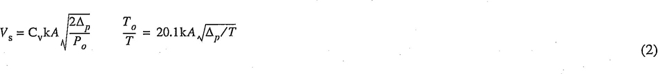
where
Cv = Calibration factor for bidirectional probe based upon air velocities in excess of 3.0 m/s (10 ft/s) in a 16 in (406 mm) duct.
k = Ratio of the average duct gas mass flow per unit area, as determined by measuring the velocity and temperature profiles across the stack, and the velocity and temperature at the center line where the bidirectional probe is located during the test.
A = Cross-sectional area of the duct at the location of the probe, m2.
δp = Differential pressure measured with the probe, Pa.
Po = Density of air (kg/m3) at the reference temperature To, K.
T = Duct gas temperature, K.
The burner shall be ignited, and gas flows shall be adjusted to the values specified below. The burner, at an angle of 20° from the horizontal, shall be positioned in front of the cable tray and 75 mm ± 5 mm (3 in ± 0.2 in) from the nearest cable surface as shown in Fig 3.
The propane flow rate shall be 220 cm3/s ± 8 cm3/s (28 ft3/h ± 1 ft3/h) when corrected to standard temperature and pressure (20 °C, 101 kPa). This propane flow rate provides a theoretical heat output of 20 kW. The actual heat output will be less, due to incomplete combustion of the propane at the burner.
When propane other than the grade specified in 4.8 is used, the propane flow rate shall be adjusted to maintain the 20 kW heat input. In the event of dispute, the test results obtained using the propane specified in 4.8 shall be final.
To verify the amount of gas consumed during the test, the propane tank shall be weighed before and after the test. Based upon the heat content specified in 4.8, 539 grams (1 lb, 3 oz) of propane should be consumed during the 20 min test. If a mass flow controller is used, it shall not be required to weigh the propane tank.
The air flow rate shall be 1280 cm3/s ± 80 cm3/s (163 ft3/h ± 10 ft3/h) when corrected to standard temperature and pressure.
9The burner flame shall impinge on the specimens for a continuous period of 20 min.
At the end of the 20 min period, the burner flame shall be extinguished, and the cable fire (if any) allowed to self-extinguish. The time of afterburn shall be recorded.
After burning has ceased, the cables shall be wiped clean, and the longest charred or affected portion of the specimens measured and recorded to the nearest 25 mm (1 in).
Cable damage shall be determined by measuring the distance of charring or the affected portion above the horizontal line from the lower edge of the burner face.
The limit of charring shall be determined by pressing against the cable surface with a sharp object. Where the surface of the cable changes from a resilient surface to a brittle or crumbling surface, the limit of charring has been determined. Distortion of the outer surface of the cable, such as blistering or melting, immediately above the char shall be included in the damage measurement.
On cable constructions that do not have charring, the limit for the affected portion shall be defined as “the point where the overall diameter is visibly reduced or increased.”
The sample shall have complied with this standard if the length of damage (charring or other affected portion) does not exceed 1.5 m (4.9 ft), when measured in accordance with 7.1, in all tests.
A Test Record Data Sheet shall be completed for each flame test. The following information shall be recorded for each test: