In order to promote public education and public safety, equal justice for all, a better informed citizenry, the rule of law, world trade and world peace, this legal document is hereby made available on a noncommercial basis, as it is the right of all humans to know and speak the laws that govern them.
FOURTH EDITION
PLEASE NOTE:
The information contained in this document was obtained from sources believed to be reliable and is based on technical information and experience currently available from members of the Compressed Gas Association, Inc. and others. However, the Association or its members, jointly or severally, make no guarantee of the results and assume no liability or responsibility in connection with the information or suggestions herein contained. Moreover, it should not be assumed that every acceptable commodity grade, test or safety procedure or method, precaution, equipment or device is contained within, or that abnormal or unusual circumstances may not warrant or suggest further requirements or additional procedure.
This document is subject to periodic review, and users are cautioned to obtain the latest edition. The Association invites comments and suggestions for consideration. In connection with such review, any such comments or suggestions will be fully reviewed by the Association after giving the party, upon request, a reasonable opportunity to be heard. Proposed changes may be submitted via the Internet at our website, www.cganet.com.
This document should not be confused with federal, state, provincial, or municipal specifications or regulations; insurance requirements; or national safety codes. While the Association recommends reference to or use of this document by government agencies and others, this document is purely voluntary and not binding unless adopted by reference in regulations.
A listing of all publications, audiovisual programs, safety and technical bulletins, and safety posters is available via the Internet at our website at www.cganet.com. For more information contact CGA at Phone: 703-788-2700, ext. 799. E-mail: customerservice@cganet.com.
Work Item 06-48
Cylinder Valve Committee
NOTE—Technical changes from the previous edition are underlined.
NOTE—Appendices A and B (Normative) are requirements.
NOTE—Appendix C (Informative) is for information only.
FOURTH EDITION: 2005
THIRD EDITION: 2003
SECOND EDITION: 1996
FIRST EDITION: 1989
© 2005 The Compressed Gas Association, Inc. All rights reserved.
All materials contained in this work are protected by United States and international copyright laws. No part of this work may be reproduced or transmitted in any form or by any means, electronic or mechanical including photocopying, recording, or any information storage and retrieval system without permission in writing from The Compressed Gas Association, Inc. All requests for permission to reproduce material from this work should be directed to The Compressed Gas Association, Inc., 14501 George Carter Way, Suite 103, Chantilly VA 20151 You may not alter or remove any trademark, copyright or other notice from this work.
ii| 1) The temperature of the cryogenic gases is always below –130 °F (–90 °C). 2) If pressure at 130 °F (54 °C) is over 600 psi (4140 kPa), use digit 1. 3) When separate outlet for liquid withdrawal is specified. |
||||
| Contents | Page | |||
| 1 | Introduction | 1 | ||
| 2 | Scope | 1 | ||
| 3 | Definitions | 2 | ||
| 4 | Types of pressure relief devices | 2 | ||
| 4.1 | Type CG-1 | 2 | ||
| 4.2 | Type CG-2 | 2 | ||
| 4.3 | Type CG-3 | 3 | ||
| 4.4 | Type CG-4 | 3 | ||
| 4.5 | Type CG-5 | 3 | ||
| 4.6 | Type CG-7 | 3 | ||
| 5 | Description of method and procedures | 4 | ||
| 5.1 | Algorithm | 4 | ||
| 5.2 | Responsibility for selection of the pressure relief device | 4 | ||
| 5.3 | Guidelines for use of the algorithm | 4 | ||
| 5.4 | Procedure for assigning a pressure relief device for a mixture | 5 | ||
| 6 | References | 32 | ||
| Figures | ||||
| Figure 1—Algorithm for gas mixtures (U.S. customary units) | 6 | |||
| Figure 2—Algorithm for gas mixtures (SI units) | 7 | |||
| Examples | ||||
| Example 1—100 ppm hydrogen, balance nitrogen (U.S. customary units) | 9 | |||
| Example 2—5% trimethylamine, balance sulfur hexafluoride (U.S. customary units) | 11 | |||
| Example 3—5% trimethylamine, balance sulfur hexafluoride (SI units) | 13 | |||
| Example 4—0.5% oxygen, 0.5% nitrogen, balance methane (U.S. customary units) | 15 | |||
| Example 5—12% ethylene oxide, balance dichlorodifluoromethane (R12) (U.S. customary units) | 17 | |||
| Example 6—5% carbon dioxide, balance oxygen (DOT 3AA2015 cylinder) (U.S. customary units) | 19 | |||
| Example 7—5% carbon dioxide, balance oxygen (DOT 3E1800 cylinder) (U.S. customary units) | 21 | |||
| Example 8—Multicomponent gas mixtures (U.S. customary units) | 23 | |||
| Example 9—20% arsine, balance hydrogen (U.S. customary units) | 25 | |||
| Example 10—2% arsine, balance hydrogen (U.S. customary units) | 27 | |||
| Example 11—0.2% arsine, balance hydrogen (U.S. customary units) | 29 | |||
| Example 12—5% arsine, 10% phosphine, balance hydrogen (U.S. customary units) | 31 | |||
| Appendices | ||||
| Appendix A—FTSC numerical code for gas classification (Normative) | 33 | |||
| Appendix B—List of gases (Normative) | 34 | |||
| Appendix C—Sample worksheet (Informative) | 39 | |||
This publication presents a method for selecting pressure relief devices (PRDs) for compressed gas mixtures packaged in cylinders having water capacities of 1000 lb (454 kg) (see U.S. Department of Transportation [DOT] Title 49 of the U.S. Code of Federal Regulations [49 CFR] Part 173.301 [f]). This standard also applies to DOT 3AX, 3AAX, and 3T cylinders having water capacities over 1000 lb (454 kg) that comply with the specifications, charging, and maintenance regulations of DOT or the corresponding specifications and regulations of Transport Canada (TC) [1, 2].1
The task is more involved than the method for determining the appropriate valve outlet connections for gas mixtures. For the latter, as described in CGA V-7, Standard Method of Determining Cylinder Valve Outlet Connections for Industrial Gas Mixtures, mixture component rating numbers are assigned to the various compressed gases based on the physical properties of the gases, i.e., flammability, toxicity, state of the gas, and corrosiveness [3]. The higher the mixture component rating number (1 through 6), the more influential that gas becomes in determining the outlet connection for the mixture in which that gas is a component.
Valve outlet connection assignments are broadly separated into connections for groups of gases having similar properties such as high and low pressure, flammability, corrosivity, toxicity, and inertness. Since 1978 this system has proven satisfactory in avoiding hazardous connections.
The physical characteristics of a mixture consisting of several pure gases could be dramatically different depending on the concentration of each gas in the mixture. Depending on these concentrations, a mixture could be flammable or nonflammable, toxic or nontoxic, liquified or nonliquefied, corrosive or noncorrosive. Since the mixture is released to the atmosphere when the relief device functions, the characteristics of the escaping gas mixture must be well defined.
It was concluded that a method would have to be established for assigning the proper relief device for each mixture, just as is done for pure gases in CGA S-1.1, Pressure Relief Device Standards—Part 1—Cylinders for Compressed Gases [4]. To use this method, the proper FTSC code must be determined (see Appendix A). In some cases, determining the proper FTSC number is straightforward. However, in other cases the appropriate FTSC number is not as obvious, and in most cases this determination is the responsibility of the gas mixture producer. It must be understood that some of the considerations made in determining the selection of the PRD used in this publication are based on experience.
The method outlined in this publication is designed to handle the proliferation of mixtures entering the commercial market.
The continued use of previously recognized and installed devices is not restricted by this edition of the standard. However, if a PRD is replaced, the new device shall meet the requirements of this standard.
This method is applicable to the determination of the proper PRD to use with compressed gas mixtures in cylinders defined in Section 1.
This method is limited to those compressed gas mixtures with known flammability, toxicity (LC50), state, and corrosivity. In addition, the DOT/TC rating and dimensions of the cylinder and the final pressure must be known.
For the selection of PRDs for a single component compressed gas, see CGA S-1.1 [4]. For multicomponent compressed gases (mixtures), the method for selection of relief devices in this publication should be used. Where a mixture is predominantly made up of a single component in a mixture, the gas producer shall determine whether the properties of this mixture dictate it being treated as a single component compressed gas or a gas mixture.
1 References are shown by bracketed numbers and are listed in order of appearance in the reference section.
1For the purpose of this standard, the following definitions apply.
Series of formatted questions that when answered in sequence will result in the selection of one or more PRDs.
Pressurization of the vapor space above a liquefied gas or liquid for the purpose of liquid withdrawal.
Charged settled pressure at 70 °F (21.1 °C).
Any material that exerts in a container an absolute pressure of at least 40.6 psia (280 kPa) at 68 °F (20 °C).2
Purposeful combination of two or more commodities resulting in a compressed gas.
Site where the compressed gas mixture is packaged into cylinders and the personnel who perform the work.
Concentration of a substance in air for which exposure for a specified length of time is expected to cause the death of 50% of the entire defined experimental animal population.
NOTE—See CGA P-20, Standard for the Classification of Toxic Gas Mixtures [6].
Material with a toxicity LC50 less than or equal to 200 ppm.
Material with a toxicity LC50 greater than 200 ppm and less than or equal to 1000 ppm.
Material with a toxicity LC50 greater than 1000 ppm and less than or equal to 3000 ppm.
Material with a toxicity LC50 greater than 3000 ppm and less than or equal to 5000 ppm.
Types of PRDs are designated as follows:
A rupture disk.
Since this is a pressure-operated device designed to release the entire content of the container, there is no way to prevent the complete release of the content, either as a result of normal functioning or premature rupture of the device.
2 kPa shall indicate gauge pressure unless otherwise noted as (kPa, abs) for absolute pressure or (kPa, differential) for differential pressure. All kPa values are rounded off per CGA P-11, Metric Practice Guide for the Compressed Gas Industry [5].
2A fusible plug using a fusible alloy with yield temperature not over 170 °F (76.7 °C) or less than 157 °F (69.4 °C). Nominal yield temperature is 165 °F (73.9 °C).
Since this is a thermally operated device, it does not protect against overpressure from improper charging practices. This device releases the entire lading of the container when it functions, and is limited to use on cylinders of 500 psig (3450 kPa) service pressure or less. This device may be used in higher service pressure cylinders provided that the product pressure does not exceed 500 psig (3450 kPa) at 68 °F (20 °C) and the device type is mandated by this standard or TC regulations.
A fusible plug using a fusible alloy with yield temperature not over 224 °F (106.7 °C) or less than 208 °F (97.8 °C). Nominal yield temperature is 212 °F (100 °C).
Same as for CG-2 (see 4.2.1).
A combination rupture-disk/fusible-plug device using a fusible alloy with yield temperature not over 170 °F (76.7 °C) or less than 157 °F (69.4 °C). Nominal yield temperature is 165 °F (73.9 °C).
Since this device is a combination device, it requires both excessive pressure and temperature to cause it to operate. This device will not function due to pressure unless the fusible metal is melted out first. Such a combination device cannot prevent an improperly filled (overfilled) cylinder from rupturing due to hydrostatic pressure at room temperature or any temperature below the melting temperature of the fusible metal, as will devices that contain only a rupture disk (CG-1). There is no way to prevent the complete release of the content when this device functions.
A combination rupture-disk/fusible-plug device using a fusible alloy with yield temperature not over 224 °F (106.7 °C) or less than 208 °F (97.8 °C). Nominal yield temperature is 212 °F (100 °C).
Same as for CG-4 (see 4.4.1).
A pressure relief valve.
This device maintains the pressure in the container at a limit as determined by the set pressure of the valve and thus does not protect against rupture of the container when the application of heat weakens the container to the point where its rupture pressure is less than the operating pressure of the device.
WARNING: PRDs might not prevent rupture of a cylinder under all conditions of fire exposure. When the heat transferred to the cylinder is localized, intensive, and remote to the relief device, or where the fire builds extremely rapidly such as in an explosion and is of very high intensity, the cylinder can weaken sufficiently to rupture before the relief device operates or while it is operating.
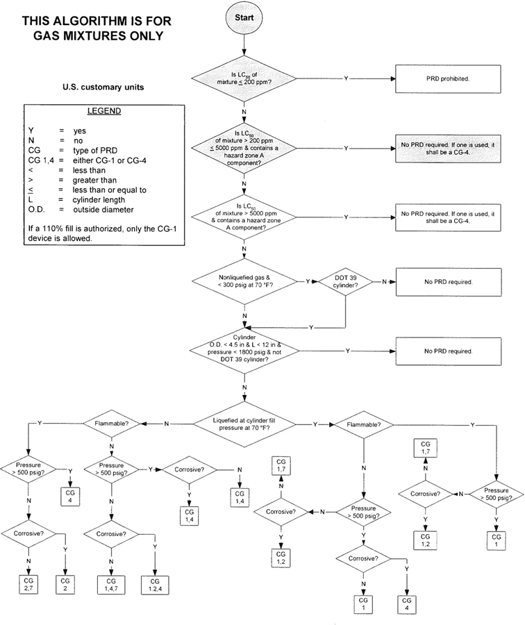
3The algorithm has been designed to assist the gas mixture producer to quickly and correctly determine the appropriate PRD(s) for gas mixtures. The algorithm is shown in Figure 1 (U.S. customary units) and Figure 2 (SI units). Application of the algorithm is illustrated for selected gas mixtures in Examples 1-12.
The responsibility for the selection of the PRD lies with the gas mixture producer. Although the algorithm does permit a degree of flexibility in the selection of the relief device for some cylinders, the flammability, toxicity (LC50), state, and corrosivity of the mixture shall be determined first. Appendix A provides the definitions of the FTSC codes. Appendix B lists the codes for most of the gases that are commonly used in mixtures.
The following guidelines and constraints govern the use of the algorithm:
– The final mixture properties, i.e., flammability, toxicity, state of the gas, corrosiveness, and final pressure are known by the gas mixture producer.
– The producer shall determine the mixture’s flammability. As used in the algorithm, “Flammable” means having an “F” rating of 2, 3, or 5.
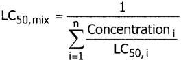
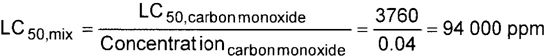
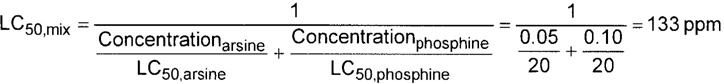
– The producer shall determine the mixture’s toxicity. In accordance with DOT (49 CFR 173.115), the toxicity of the mixture can be calculated from the concentrations and toxicity of the components as follows (see CGA P-20 for additional details regarding mixture toxicity calculations) [6]:
Where:
n = Number of toxic components
Concentrationi = Concentration of the ith toxic component, expressed as a decimal fraction of the whole, e.g., 0.05 for a 5% mixture and 5 × 10⁻⁶ for a 5 ppm mixture. This number is dimensionless
LC50, i = LC50 of the ith toxic component, in ppm
LC50, mix = LC50 of the mix, in ppm
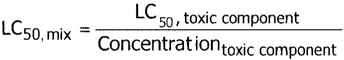
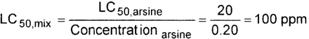
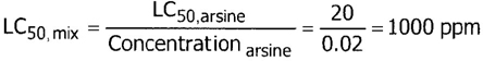
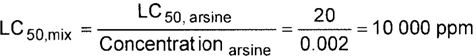
For a mixture with a single toxic component, this simplifies to:
– As used in the algorithm, “Corrosive” means having a “C” rating of 1 or greater.
– Other definitions conform with those of DOT or TC if applicable.
– Pressurization of the vapor space above a condensed liquid for the purpose of withdrawal does not constitute a gas mixture.
– If a 110% fill is authorized, only the CG-1 device is allowed.
4– When the CG-2 device is indicated, it allows use of the CG-3 device where the final mixture properties permit. Likewise when the CG-4 device is indicated, the CG-5 device may be used where the final mixture properties permit.
NOTE—The decision of whether the CG-2 or CG-3 device is used as well as whether the CG-4 or CG-5 device is used shall be made by the gas mixture producer as authorized by the latest edition of CGA S-1.1 based on the producer’s classification of the final mixture according to its properties [4].
– Where two or more types of PRDs are indicated, only one of them is required. Care should be taken that the selection made conforms to all requirements in 49 CFR and CGA S-1.1 [1, 4]. For example, see CGA S-1.1 regarding the requirements for relief devices at both ends of the cylinder if the cylinder length exceeds 30 in (762 mm) [4].
With an understanding of the guidelines in 5.3, the procedures below shall be followed to assign a PRD for a mixture (see Appendix C for a worksheet format):
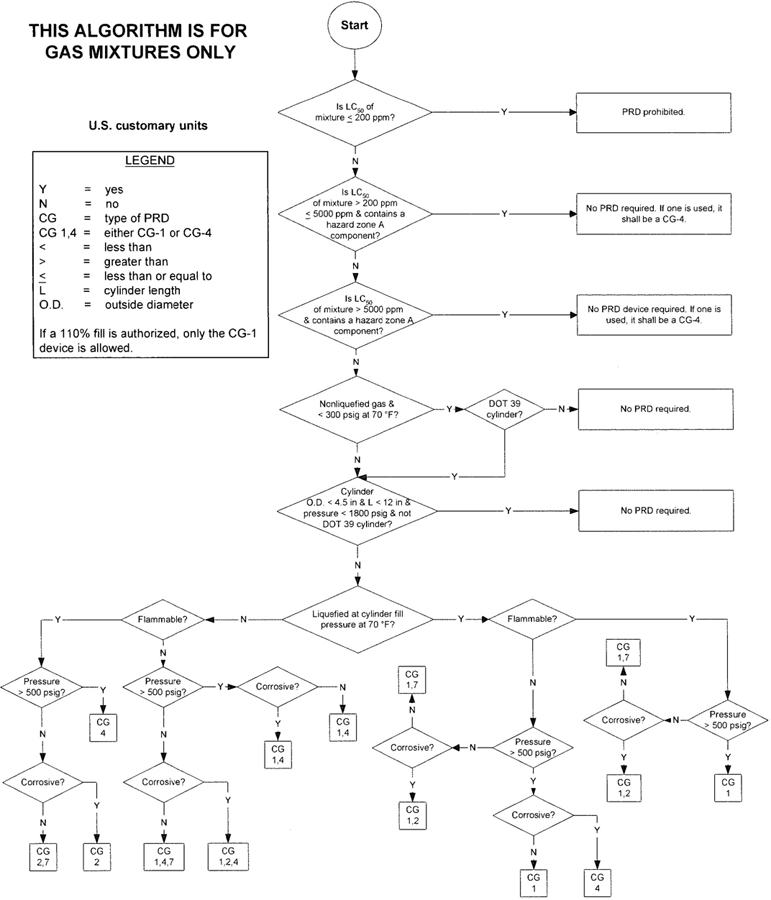
Figure 1—Algorithm for gas mixtures (U.S. customary units)
6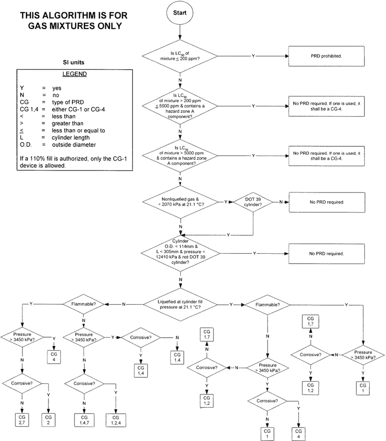
Figure 2—Algorithm for gas mixtures (SI units)
7Worksheet for Example 1
100 ppm hydrogen, balance nitrogen
(U.S. customary units)
| COMPONENTS | CONCENTRATION | F | T | S | C | LC50 | |
|---|---|---|---|---|---|---|---|
| 1. | Hydrogen | 100 ppm | 2 | 1 | 6 | 0 | > 5000 ppm |
| 2. | Nitrogen | Balance | 0 | 1 | 6 | 0 | > 5000 ppm |
| DOT CYLINDER RATING: | 3AA2015 | |
| FINAL PRESSURE: | 2000 psig at 70 °F | |
| 2226 psig at 130 °F | ||
| DIMENSIONS: | 9 in diameter | 51 in length |
| MIXTURE FTSC: | 0 1 6 0 | |
| MIXTURE LC50: | > 5000 ppm, no Zone A component | |
STEPS ON ALGORITHM: (See Example 1)
OBSERVATIONS:

Example 1—100 ppm hydrogen, balance nitrogen (U.S. customary units)
9Worksheet for Example 2
5% trimethylamine, balance sulfur hexafluoride
(U.S. customary units)
| COMPONENTS | CONCENTRATION | F | T | S | C | LC50 | |
|---|---|---|---|---|---|---|---|
| 1. | Trimethylamine | 5% | 2 | 1 | 0 | 2 | 7000 ppm |
| 2. | Sulfur hexafluoride | Balance | 0 | 1 | 0 | 0 | > 5000 ppm |
| DOT CYLINDER RATING: | 3AA2015 | |
| FINAL PRESSURE: | 250 psig at 70 °F | |
| 278 psig at 130 °F | ||
| DIMENSIONS: | 9 in diameter | 51 in length |
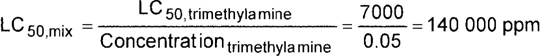
| MIXTURE FTSC: | 2 1 0 2 |
| MIXTURE LC50: | 140 000 ppm, no Zone A component |
STEPS ON ALGORITHM: (See Example 2)
OBSERVATIONS:
No PRD is required.
10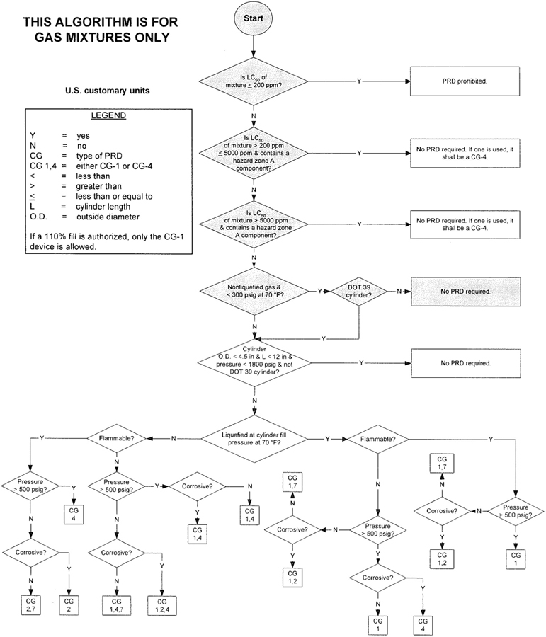
Example 2—5% trimethylamine, balance sulfur hexafluoride (U.S. customary units)
11Worksheet for Example 3
5% trimethylamine, balance sulfur hexafluoride
(SI units)
| COMPONENTS | CONCENTRATION | F | T | S | C | LC50 | |
|---|---|---|---|---|---|---|---|
| 1. | Trimethylamine | 5% | 2 | 1 | 0 | 2 | 7000 ppm |
| 2. | Sulfur hexafluoride | Balance | 0 | 1 | 0 | 0 | > 5000 ppm |
| DOT CYLINDER RATING: | 3AA2015 | |
| FINAL PRESSURE: | 1720 kPa at 21.1 °C | |
| 1916 kPa at 54.4 °C | ||
| DIMENSIONS: | 229 mm diameter | 1295 mm length |
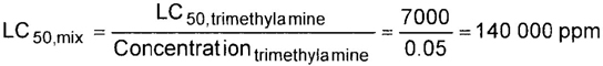
| MIXTURE FTSC: | 2 1 0 2 |
| MIXTURE LC50: | 140 000 ppm, no Zone A component |
STEPS ON ALGORITHM: (See Example 3)
OBSERVATIONS:
No PRD is required.
12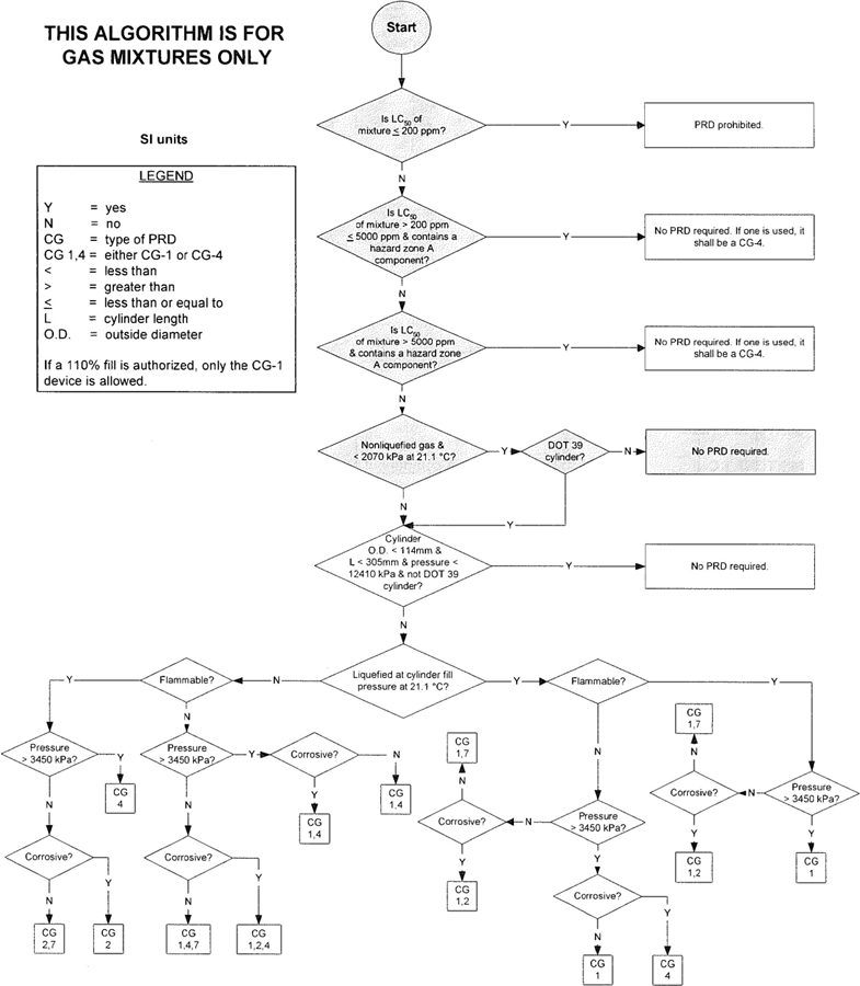
Example 3—5% trimethylamine, balance sulfur hexafluoride (SI units)
13Worksheet for Example 4
0.5% oxygen, 0.5% nitrogen, balance methane
(U.S. customary units)
| COMPONENTS | CONCENTRATION | F | T | S | C | LC50 | |
|---|---|---|---|---|---|---|---|
| 1. | Oxygen | 0.5% | 4 | 0 | 6 | 0 | > 5000 ppm |
| 2. | Nitrogen | 0.5% | 0 | 1 | 6 | 0 | > 5000 ppm |
| 3. | Methane | Balance | 2 | 1 | 6 | 0 | > 5000 ppm |
| DOT CYLINDER RATING: | 3AX2400 | |
| FINAL PRESSURE: | 2400 psig at 70 °F | |
| 2671 psig at 130 °F | ||
| DIMENSIONS: | 9.5 in diameter | 252 in length |
All mixture components have LC50 values above 5000 ppm, but oxygen is < 19.5%, therefore the T code is 1.
| MIXTURE FTSC: | 2 1 6 0 |
| MIXTURE LC50: | >5000 ppm, no Zone A component |
STEPS ON ALGORITHM: (See Example 4)
OBSERVATIONS:

Example 4—0.5% oxygen, 0.5% nitrogen, balance methane (U.S. customary units)
15Worksheet for Example 5
12% ethylene oxide, balance dichlorodifluoromethane (R12)
(U.S. customary units)
| COMPONENTS | CONCENTRATION | F | T | S | C | LC50 | |
|---|---|---|---|---|---|---|---|
| 1. | Ethylene oxide | 12% | 5 | 2 | 0 | 0 | 2920 ppm |
| 2. | Refrigerant-12 | Balance | 0 | 1 | 0 | 0 | > 5000 ppm |
| DOT CYLINDER RATING: | 4BA240 | |
| FINAL PRESSURE | 70 psig at 70 °F | |
| 78 psig at 130 °F | ||
| DIMENSIONS: | 10.5 in diameter | 55 in length |

| MIXTURE FTSC: | 0 1 2 0 |
| MIXTURE LC50: | > 5000 ppm, no Zone A component |
STEPS ON ALGORITHM: (See Example 5)
OBSERVATIONS:
Example 5—12% ethylene oxide, balance dichlorodifluoromethane (R12) (U.S. customary units)
17Worksheet for Example 6
5% carbon dioxide, balance oxygen
(DOT 3AA2015 cylinder)
(U.S. customary units)
| COMPONENTS | CONCENTRATION | F | T | S | C | LC50 | |
|---|---|---|---|---|---|---|---|
| 1. | Carbon Dioxide | 5% | 0 | 1 | 6 | 0 | > 5000 ppm |
| 2. | Oxygen | Balance | 4 | 0 | 6 | 0 | > 5000 ppm |
| DOT CYLINDER RATING: | 3AA2015 | |
| FINAL PRESSURE: | 2000 psig at 70 °F | |
| 2226 psig at 130 °F | ||
| DIMENSIONS: | 9 in diameter | 51 in length |
ALL mixture components have LC50 values above 5000 ppm, and oxygen is > 19.5%, therefore the T code is 0.
| MIXTURE FTSC: | 4 0 6 0 |
| MIXTURE LC50: | > 5000 ppm, no Zone A component |
STEPS ON ALGORITHM: (See Example 6)
OBSERVATIONS:

Example 6—5% carbon dioxide, balance oxygen (DOT 3AA2015 cylinder) (U.S. customary units)
19Worksheet for Example 7
5% carbon dioxide, balance oxygen
(DOT 3E1800 cylinder)
(U.S. customary units)
| COMPONENTS | CONCENTRATION | F | T | S | C | LC50 | |
|---|---|---|---|---|---|---|---|
| 1. | Carbon dioxide | 5% | 0 | 1 | 6 | 0 | > 5000 ppm |
| 2. | Oxygen | Balance | 4 | 0 | 6 | 0 | > 5000 ppm |
| DOT CYLINDER RATING: | 3E1800 | |
| FINAL PRESSURE: | 1750 psig at 70 °F | |
| 1948 psig at 130 °F | ||
| DIMENSIONS: | 2 in diameter | 12 in length |
All mixture components have LC50 values above 5000 ppm and oxygen is > 19.5%, therefore the T code is 0.
| MIXTURE FTSC: | 4 0 6 0 |
| MIXTURE LC50: | > 5000 ppm, no Zone A component |
STEPS ON ALGORITHM: (See Example 7)
OBSERVATIONS:
The pressure in the cylinder at 130 °F is < 5/4 times the service pressure of 1800 psig.
20
Example 7—5% carbon dioxide, balance oxygen (DOT 3E1800 cylinder) (U.S. customary units)
21Worksheet for Example 8
Multicomponent gas mixtures
(U.S. customary units)
| COMPONENTS | CONCENTRATION | F | T | S | C | LC50 | |
|---|---|---|---|---|---|---|---|
| 1. | Methane | 4% | 2 | 1 | 6 | 0 | > 5000 ppm |
| 2. | Propane | 4% | 2 | 1 | 0 | 0 | > 5000 ppm |
| 3. | Ethane | 4% | 2 | 1 | 1 | 0 | > 5000 ppm |
| 4. | Carbon Monoxide | 4% | 2 | 2 | 6 | 0 | 3760 ppm |
| 5. | Hydrogen | 4% | 2 | 1 | 6 | 0 | > 5000 ppm |
| 6. | Oxygen | 5.5% | 4 | 0 | 6 | 0 | > 5000 ppm |
| 7. | Nitrogen | Balance | 0 | 1 | 6 | 0 | > 5000 ppm |
| DOT CYLINDER RATING: | 3AA2015 | |
| FINAL PRESSURE: | 1650 psig at 70 °F | |
| 1837 psig at 130 °F | ||
| DIMENSIONS: | 9 in diameter | 51 in length |
| MIXTURE FTSC: | 2 1 6 0 |
| MIXTURE LC50: | 94 000 ppm, no Zone A component |
STEPS ON ALGORITHM: (See Example 8)
OBSERVATIONS:

Example 8—Multicomponent gas mixtures (U.S. customary units)
23Worksheet for Example 9
20% arsine, balance hydrogen
(U.S. customary units)
| COMPONENTS | CONCENTRATION | F | T | S | C | LC50 | |
|---|---|---|---|---|---|---|---|
| 1. | Arsine | 20% | 2 | 3 | 0 | 0 | 20 ppm |
| 2. | Hydrogen | Balance | 2 | 1 | 6 | 0 | > 5000 ppm |
| DOT CYLINDER RATING: | 3AA2015 | |
| FINAL PRESSURE: | 600 psig at 70 °F | |
| 669 psig at 130 °F | ||
| DIMENSIONS: | 9 in diameter | 15 in length |
Both components are flammable, so the mixture F code is 2 (as determined by the mixture producer).
The mixture is a nonliquefied gas between 600 psig and 3000 psig, so the mixture S code is 6 (as determined by the mixture producer).
Neither component is corrosive, so the mixture C code is 0 (as determined by the mixture producer).
| MIXTURE FTSC: | 2 3 6 0 |
| MIXTURE LC50: | 100 ppm |
STEPS ON ALGORITHM: (See Example 9)

Example 9—20% arsine, balance hydrogen (U.S. customary units)
25Worksheet for Example 10
2% arsine, balance hydrogen
(U.S. customary unit)
| COMPONENTS | CONCENTRATION | F | T | S | C | LC50 | |
|---|---|---|---|---|---|---|---|
| 1. | Arsine | 2% | 2 | 3 | 0 | 0 | 20 ppm |
| 2. | Hydrogen | Balance | 2 | 1 | 6 | 0 | > 5000 ppm |
| DOT CYLINDER RATING: | 3AA2015 | |
| FINAL PRESSURE: | 1000 psig at 70 °F | |
| 1113 psig at 130 °F | ||
| DIMENSIONS: | 9 in diameter | 15 in length |
Both components are flammable, so the mixture F code is 2 (as determined by the mixture producer).
The mixture is a nonliquefied gas between 500 psig and 3000 psig, so the S code is 6 (as determined by the mixture producer).
Neither component is corrosive, so the mixture C code is 0 (as determined by the mixture producer).
| MIXTURE FTSC: | 2 2 6 0 |
| MIXTURE LC50: | 1000 ppm |
STEPS ON ALGORITHM: (See Example 10)
Example 10—2% arsine, balance hydrogen (U.S. customary units)
27Worksheet for Example 11
0.2% arsine, balance hydrogen
(U.S. customary units)
| COMPONENTS | CONCENTRATION | F | T | S | C | LC50 | |
|---|---|---|---|---|---|---|---|
| 1. | Arsine | 0.2% | 2 | 3 | 0 | 0 | 20 ppm |
| 2. | Hydrogen | Balance | 2 | 1 | 6 | 0 | > 5000 ppm |
| DOT CYLINDER RATING: | 3AA2015 | |
| FINAL PRESSURE: | 1000 psig at 70°F | |
| 1113 psig at 130 °F | ||
| DIMENSIONS: | 9 in diameter | 15 in length |
Both components are flammable, so the mixture F code is 2 (as determined by the mixture producer).
The mixture is a nonliquefied gas between 500 psig and 3000 psig, so the mixture S code is 6 (as determined by the mixture producer).
Neither component is corrosive, so the mixture C code is 0 (as determined by the mixture producer).
| MIXTURE FTSC: | 2 1 6 0 |
| MIXTURE LC50: | 10 000 ppm |
STEPS ON ALGORITHM: (See Example 11)

Example 11—0.2% arsine, balance hydrogen (U.S. customary units)
29Worksheet for Example 12
5% arsine, 10% phosphine, balance hydrogen
(U.S. customary units)
| COMPONENTS | CONCENTRATION | F | T | S | C | LC50 | |
|---|---|---|---|---|---|---|---|
| 1. | Arsine | 5% | 2 | 3 | 0 | 0 | 20 ppm |
| 2. | Phosphine | 10% | 3 | 3 | 1 | 0 | 20 ppm |
| 3. | Hydrogen | Balance | 2 | 1 | 6 | 0 | > 5000 ppm |
| DOT CYLINDER RATING: | 3AA2015 | |
| FINAL PRESSURE: | 1000 psig at 70 °F | |
| 1113 psig at 130 °F | ||
| DIMENSIONS: | 9 in diameter | 15 in length |
The mixture contains three flammable components, one of which is pyrophoric, so the mixture F code is 3 (as determined by the mixture producer).
The mixture is a nonliquefied gas between 500 psig and 3000 psig, so the mixture S code is 6 (as determined by the mixture producer).
Neither component is corrosive, so the mixture C code is 0 (as determined by the mixture producer).
| MIXTURE FTSC: | 3 3 6 0 |
| MIXTURE LC50: | 133 ppm |
STEPS ON ALGORITHM: (See Example 12)

Example 12—5% arsine, 10% phosphine, balance hydrogen (U.S. customary units)
31Unless otherwise specified, the latest edition shall apply.
[1] Code of Federal Regulations, Title 49 (Transportation) Parts 100 to 180, Superintendent of Documents, U.S. Government Printing Office, Washington, DC 20402. www.gpoaccess.gov
[2] Transportation of Dangerous Goods Regulations, Transport Canada, Canadian Government Publishing, Public Works and Government Services Canada, Ottawa, ON K1A 0S9, Canada, www.tc.gc.ca
[3] CGA V-7, Standard Method of Determining Cylinder Valve Outlet Connections for Industrial Gas Mixtures, Compressed Gas Association, Inc., Compressed Gas Association, Inc., 4221 Walney Rd., 5th Floor, Chantilly, VA 20151. www.cganet.com
[4] CGA S-1.1, Pressure Relief Device Standards—Part 1—Cylinders for Compressed Gases, Compressed Gas Association, Inc., 4221 Walney Rd., 5th Floor, Chantilly, VA 20151. www.cganet.com
[5] CGA P-11, Metric Practice Guide for the Compressed Gas Industry, Compressed Gas Association, Inc., 4221 Walney Rd., 5th Floor, Chantilly, VA 20151. www.cganet.com
[6] CGA P-20, Standard for the Classification of Toxic Gas Mixtures, Compressed Gas Association, Inc., 4221 Walney Rd., 5th Floor, Chantilly, VA 20151. www.cganet.com
32| 1st Digit — FIRE POTENTIAL | ||||
| 0 | = inert | |||
| 1 | = supports combustion (oxidizing) | |||
| 2 | = flammable in air at 68 °F (20 °C) and 1 atm | |||
| 3 | = pyrophoric | |||
| 4 | = highly oxidizing | |||
| 5 | = may decompose or polymerize and is flammable | |||
| 2nd Digit — TOXICITY | ||||
| 0 | = life supporting (oxygen ≥ 19.5% in simple asphyxiant) | |||
| 1 | = LC50 > 5000 ppm | |||
| 2 | = 200 ppm < LC50 ≤ 5000 ppm | |||
| 3 | = LC50 ≤ 200 ppm | |||
| 3rd Digit — STATE OF GAS: (in the cylinder at 70° F (21° C)1) | ||||
| 0 | = noncryogenic liquefied gas (less than 500 psi) (3450 kPa)2)—gas withdrawal | |||
| 1 | = noncryogenic liquefied gas (over 500 psi) (3450 kPa)—gas withdrawal | |||
| 2 | = liquefied gas (liquid withdrawal)3) | |||
| 3 | = dissolved/absorbed gas | |||
| 4 | = nonliquefied gas—or cryogenic gas withdrawal (less than 500 psi) (3450 kPa) | |||
| 5 | = Europe only | |||
| 6 | = nonliquefied gas between 500 psi and 3000 psi (3450 kPa and 20 680 kPa) | |||
| 7 | = nonliquefied gas above 3001 psi and below 10 000 psi (20 690 kPa and 68 950 kPa) | |||
| 8 | = cryogenic gas (liquid withdrawal) above –400 °F (–240°C) | |||
| 9 | = cryogenic gas (liquid withdrawal) below –400 °F (–240°C) | |||
| 4th Digit — CORROSIVENESS: | ||||
| 0 | = noncorrosive | |||
| 1 | = nonhalogen acid forming | |||
| 2 | = basic | |||
| 3 | = halogen acid forming | |||
| FTSC Code | LC50 (ppm) | Name of gas |
|---|---|---|
| * Not a compressed gas | ||
| 5130 | Acetylene | |
| 2200 | Acrylonitrile | |
| 1060 | Air | |
| 2100 | Allene | |
| Allylene (See Methylacetylene) | ||
| 2102 | 7 338 | Ammonia, Anhydrous |
| 0303 | 30 | Antimony Pentafluoride |
| 0160 | Argon | |
| 0303 | 20 | Arsenic Pentafluoride |
| 2300 | 20 | Arsine |
| Boron Chloride (See Boron Trichloride) | ||
| Boron Fluoride (See Boron Trifluoride) | ||
| 0203 | 2 541 | * Boron Trichloride |
| 0263 | 806 | Boron Trifluoride |
| 4303 | 50 | * Bromine Pentafluoride |
| 4303 | 180 | * Bromine Trifluoride |
| 0203 | 260 | * Bromoacetone |
| 0100 | * Bromochlorodifluoromethane (R12B1) or (Halon 1211) | |
| 0100 | * Bromochloromethane (Halon 1011) | |
| 0100 | Bromodifluoromethane (HBFC-22 B1) | |
| Bromoethylene (See Vinyl Bromide) | ||
| Bromomethane (See Methyl Bromide) | ||
| 3100 | Bromotrifluoroethylene (R113B1) | |
| 0100 | Bromotrifluoromethane (R13B1 or Halon 1301) | |
| 5100 | 220 000 | 1,3 Butadiene, (Inhibited) |
| 2100 | Butane, Normal | |
| 2100 | 1-Butene | |
| 2100 | 2-Butene | |
| 0110 | Carbon Dioxide | |
| 2200 | Carbon Disulfide | |
| Carbonic Acid (See Carbon Dioxide) | ||
| 2260 | 3 760 | Carbon Monoxide |
| Carbon Oxysulfide (See Carbonyl Sulfide) | ||
| Carbon Tetrafluoride (See Tetrafluoromethane) | ||
| Carbonyl Chloride (See Phosgene) | ||
| 0213 | 360 | Carbonyl Fluoride |
| 2201 | 1 700 | Carbonyl Sulfide |
| 4203 | 293 | Chlorine |
| 4303 | 122 | Chlorine Pentafluoride |
| 4203 | 299 | Chlorine Trifluoride |
| 2100 | Chlorodifluoroethane (R142b) | |
| 0100 | Chlorodifluoromethane (R22) | |
| 0100 | Chlorodifluoromethane/Chloropentafluoroethane (Mixture) (R502) | |
| Chloroethane (See Ethyl Chloride) | ||
| Chloroethylene(See Vinyl Chloride) | ||
| 2100 | Chlorofluoromethane (R31) 34 | |
| 0100 | Chloroheptafluorocyclobutane (RC317) | |
| Chloromethane(See Methyl Chloride) | ||
| 0100 | Chloropentafluoroethane (R115) | |
| 0100 | 1-Chloro-1,2,2,2-Tetrafluoroethane (R124) | |
| 0100 | 1-Chloro-2,2,2-Trifluoroethane (R133a) | |
| 5200 | 2 000 | Chlorotrifluoroethylene (R1113) |
| 0100 | Chlorotrifluoromethane (R13) | |
| 2200 | 350 | Cyanogen |
| 0303 | 80 | Cyanogen Chloride |
| 2100 | Cyclobutane | |
| 2100 | 220 000 | Cyclopropane |
| 2160 | Deuterium | |
| 0213 | 3 120 | Deuterium Chloride |
| 0203 | 1 100 | * Deuterium Fluoride |
| 2301 | 2 | Deuterium Selenide |
| 2201 | 710 | Deuterium Sulfide |
| 5360 | 80 | Diborane |
| 0100 | 27 000 | * Dibromodifluoromethane (R12B2) (Halon 1202) |
| Dibromomethane (See Methylene Bromide) | ||
| 0100 | * 1,2 Dibromotetrafluoroethane (R114B2) (Halon 2402) | |
| 0100 | * 1,2 Dichlorodifluoroethylene (R1112a) | |
| 0100 | Dichlorodifluoromethane (R12) | |
| 0100 | Dichlorodifluoromethane/Difluoroethane Mixture (R500) | |
| 0200 | * 1,2 Dichloroethylene (R1130) | |
| 0100 | * Dichlorofluoroemethane (R21) | |
| 0100 | * 1,2 Dichlorohexafluorocyclobutane (RC316) | |
| 2100 | Dichloromethane | |
| 2203 | 314 | * Dichlorosilane |
| 0100 | * 1,1 Dichlorotetrafluoroethane (R114a) | |
| 0100 | * Dichlorotetrafluoroethane (R114) | |
| 0100 | * 2,2 Dichloro-1,1,1-Trifluoroethane (R123) | |
| Dicyan (See Cyanogen) | ||
| 3300 | 10 | * Diethylzinc |
| 2100 | 1,1 Difluoroethane (R152a) | |
| 2110 | 1,1 Difluoroethylene (R1132a) | |
| Difluoromethane (See Methylene Fluoride) | ||
| 2102 | * Dimethylamine, Anhydrous | |
| Dimethyl Disulfide (See Methyl Disulfide) | ||
| 2100 | Dimethyl Ether | |
| 2100 | > 5 000 | * Dimethylsilane |
| Dimethyl Sulfide (See Methyl Sulfide) | ||
| 2100 | * 2,2 Dimethylpropane | |
| 0303 | 2 | Diphosgene |
| 2110 | Ethane | |
| Ethanethiol (See Ethyl Mercaptan) | ||
| 2100 | * Ethylacetylene | |
| 2100 | * Ethyl Chloride | |
| 0303 | 36 | Ethyldichloroarsine 35 |
| 2160 | Ethylene | |
| 5200 | 2 920 | * Ethylene Oxide |
| 2100 | * Ethyl Ether | |
| 2100 | Ethyl Fluoride | |
| 2100 | Ethyl Mercaptan | |
| 4343 | 185 | Fluorine |
| Fluoroform (R23) (See Trifluoromethane) | ||
| 2200 | 622 | Germane |
| 0203 | Germanium Tetrachloride | |
| 0160 | Helium | |
| Helium/Oxygen Mixture | ||
| 2300 | 10 | Heptafluorobutyronitrile |
| 0100 | Heptafluoropropane (HFC-227 ea) | |
| 0203 | 470 | Hexafluoroacetone |
| 2100 | > 5 000 | Hexafluorocyclobutene |
| 0100 | Hexafluoroethane (R116) | |
| 0100 | Hexafluoropropylene (R1216) | |
| 2160 | Hydrogen | |
| 0203 | 2 860 | Hydrogen Bromide |
| 0213 | 3 120 | Hydrogen Chloride |
| 5301 | 140 | Hydrogen Cyanide |
| 0203 | 1 276 | * Hydrogen Fluoride |
| 0203 | 2 860 | Hydrogen Iodide |
| 2301 | 2 | Hydrogen Selenide |
| 2201 | 712 | Hydrogen Sulfide |
| 4303 | 120 | * Iodine Pentafluoride |
| 0203 | Iodomethane | |
| 2100 | Isobutane | |
| 2100 | Isobutylene | |
| 0160 | Krypton | |
| 0303 | Lewisite (Dichloro 2-Chloro Vinyl Arsine) | |
| 2160 | Methane | |
| 2100 | Methylacetylene | |
| 0200 | 850 | * Methyl Bromide |
| 2100 | * 3-Methyl-1-Butene | |
| 2100 | 8 300 | Methyl Chloride |
| 0303 | Methyldichloroarsine | |
| 2300 | Methyl Disulfide | |
| 2203 | * Methylene Bromide | |
| 2110 | Methyl Fluoride (R41) | |
| 2110 | Methylene Fluoride (R32) | |
| 2100 | * Methyl Formate | |
| 0303 | * Methyl Iodide | |
| 2201 | 1 350 | Methyl Mercaptan |
| 2100 | >5 000 | Methylsilane |
| 2100 | Methyl Sulfide | |
| 2102 | * Monoethylamine | |
| 2102 | Monomethylamine, Anhydrous 36 | |
| 0303 | 4 | Mustard Gas |
| 2160 | Natural Gas | |
| 0160 | Neon | |
| 2300 | 20 | * Nickel Carbonyl |
| 4361 | 115 | Nitric Oxide |
| 0160 | Nitrogen | |
| 4301 | 115 | * Nitrogen Dioxide |
| 4301 | * Nitrogen Tetroxide | |
| 4160 | 6 700 | Nitrogen Trifluoride |
| 4301 | 115 | Nitrogen Trioxide |
| 0303 | 35 | Nitrosyl Chloride |
| 0303 | Nitrosyl Fluoride | |
| 4110 | Nitrous Oxide | |
| 0303 | Nitryl Fluoride | |
| 0100 | Octafluorocyclobutane (RC318) | |
| 0200 | * Octafluorocyclopentene (C5F8) | |
| 0100 | Octafluoropropane (R218) | |
| 4060 | Oxygen | |
| 4343 | 2.6 | Oxygen Difluoride |
| 4330 | 9 | Ozone (Dissolved in R13) |
| 3300 | 10 | * Pentaborane |
| 0100 | Pentafluoroethane (HFC-125) | |
| 2300 | 10 | Pentafluoropropionitrile |
| 4203 | 770 | Perchloryl Fluoride |
| 2200 | Perfluorobutadiene | |
| 0100 | * Perfluorobutane (FC-3-1-10) | |
| 0100 | 12 000 | * Perfluoro-2-Butene |
| 0303 | 5 | Phenylcarbylamine Chloride |
| 0303 | 5 | Phosgene |
| 3310 | 20 | Phosphine |
| 0203 | 255 | Phosphorous Pentafluoride |
| 0203 | 425 | Phosphorous Trifluoride |
| 2100 | Propane | |
| 2100 | Propylene | |
| 3160 | 19 000 | Silane |
| 0203 | 750 | * Silicon Tetrachloride |
| 0263 | 450 | Silicon Tetrafluoride |
| 5300 | 20 | Stibine |
| 0201 | 2 520 | Sulfur Dioxide |
| 0100 | Sulfur Hexafluoride | |
| 0303 | 40 | Sulfur Tetrafluoride |
| 0200 | 3 020 | Sulfuryl Fluoride |
| 0100 | Tetrachloromethane | |
| 0100 | 1,1,1,2 Tetrafluoroethane (R-134a) | |
| 5100 | Tetrafluoroethylene-lnhibited (R1114) | |
| 4340 | 100 | Tetrafluorohydrazine |
| 0160 | Tetrafluoromethane (R-14) | |
| 2200 | * Tetramethyllead 37 | |
| 0100 | * Trichlorofluoromethane (R11) | |
| 0100 | Trichloroethylene | |
| 2203 | 1 040 | * Trichlorosilane |
| 0100 | * 1,1,1 Trichlorotrifluoroethane (R113a) | |
| 0100 | * 1,1,2 Trichlorotrifluoroethane (R113) | |
| 3300 | 10 | Triethylaluminum |
| 3200 | 1 400 | Triethylborane |
| 2200 | 500 | Trifluoroacetonitrile |
| 0203 | 208 | Trifluoroacetylchloride |
| 2100 | 1,1,1 Trifluoroethane (R143a) | |
| 0110 | Trifluoromethane (HFC-23) | |
| 4363 | Trifluoromethyl Hypofluorite | |
| 0200 | Trifluoromethyl Iodide | |
| 2102 | 7 000 | * Trimethylamine |
| 2100 | > 5 000 | * Trimethylsilane |
| 3300 | 20 | Trimethylstibine |
| 0203 | 213 | * Tungsten Hexafluoride |
| 0303 | * Uranium Hexafluoride | |
| 5100 | >5 000 | * Vinyl Bromide |
| 5100 | >5 000 | Vinyl Chloride |
| 5100 | >5 000 | Vinyl Fluoride |
| 5100 | >5 000 | Vinyl Methyl Ether |
| 0160 | Xenon | |
| COMPONENTS | CONCENTRATION | F | T | S | C | LC50 | |
|---|---|---|---|---|---|---|---|
| 1. | |||||||
| 2. | |||||||
| 3. | |||||||
| 4. | |||||||
| 5. |
| DOT CYLINDER RATING: | |
| FINAL PRESSURE | psig @ 70 °F |
| psig @ 130 °F | |
| CYLINDER DIMENSIONS: | |
| MIXTURE FTSC: | |
| MIXTURE LC50: | |