In order to promote public education and public safety, equal justice for all, a better informed citizenry, the rule of law, world trade and world peace, this legal document is hereby made available on a noncommercial basis, as it is the right of all humans to know and speak the laws that govern them.
BRITISH STANDARD
BS EN
13000:2004
The European Standard EN 13000:2004 has the status of a British Standard
ICS 53.020.20
NO COPYING WITHOUT BSI PERMISSION EXCEPT AS PERMITTED BY COPYRIGHT LAW
This British Standard is the official English language version of EN 13000:2004. It supersedes BS 1757:1986 which is withdrawn.
The UK participation in its preparation was entrusted by Technical Committee MHE/3, Cranes and derricks, to Subcommittee MHE/3/5, Mobile cranes, which has the responsibility to:
— aid enquirers to understand the text;
— present to the responsible international/European committee any enquiries on the interpretation, or proposals for changes, and keep UK interests informed;
— monitor related international and European developments and promulgate them in the UK.
A list of organizations represented on this subcommittee can be obtained on request to its secretary.
Cross-references
The British Standards which implement international or European publications referred to in this document may be found in the BSI Catalogue under the section entitled “International Standards Correspondence Index”, or by using the “Search” facility of the BSI Electronic Catalogue or of British Standards Online.
This publication does not purport to include all the necessary provisions of a contract. Users are responsible for its correct application.
Compliance with a British Standard does not of itself confer immunity from legal obligations.
Summary of pages
This document comprises a front cover, an inside front cover, the EN title page, pages 2 to 108, an inside back cover and a back cover.
The BSI copyright notice displayed in this document indicates when the document was last issued.
Amendments issued since publication
| Amd. No. | Date | Comments | ||||
|---|---|---|---|---|---|---|
| Key:• = mandatory, ο = if required, – = not relevant, L = load test, F = functional check, V = visual check | ||||||
This British Standard was published under the authority of the Standards Policy and Strategy Committee on 4 January 2006
© BSI 4 January 2006
ISBN 0 580 47272 8
iiiEUROPEAN STANDARD
NORME EUROPÉENNE
EUROPäISCHE NORM
EN 13000
June 2004
ICS 53.020.20
English version
Cranes - Mobile cranes
Appareils de levage à charge suspendue - Grues mobiles Krane - Fahrzeugkrane
This European Standard was approved by CEN on 22 April 2004.
CEN members are bound to comply with the CEN/CENELEC Internal Regulations which stipulate the conditions for giving this European Standard the status of a national standard without any alteration. Up-to-date lists and bibilographical references concerning such national standards may be obtained on application to the Central Secretariat or to any CEN member.
This European Standard exists in three official versions (English, French, German). A version in any other language made by translation under the responsibility of a CEN member into its own language and notified to the Central Secretariat has the same status as the official versions.
CEN members are the national standards bodies of Austria, Belgium, Cyprus, Czech Republic, Denmark, Estonia, Finland, France, Germany, Greece, Hungary, Iceland, Ireland, Italy, Latvia, Lithuania, Luxembourg, Malta, Netherlands, Norway, Poland, Portugal, Slovakia, Slovenia, Spain, Sweden, Switzerland and United Kingdom.

Management Centre: rue de Stassart, 36 B-1050 Brussels
© 2004 CEN All rights of exploitation in any form and by any means reserved worldwide for CEN national Members. Ref. No. EN 13000:2004: E
1| page | ||
| 1 | Scope | 7 |
| 2 | Normative references | 7 |
| 3 | Terms and definitions | 10 |
| 4 | Safety requirements and/or protective measures | 13 |
| 4.1 | Structures and components | 13 |
| 4.1.1 | General | 13 |
| 4.1.2 | Load effects | 14 |
| 4.1.3 | Limit states | 19 |
| 4.2 | Equipment and devices | 21 |
| 4.2.1 | General principles | 21 |
| 4.2.2 | Control station | 21 |
| 4.2.3 | Protection against falling tools | 23 |
| 4.2.4 | Seats | 24 |
| 4.2.5 | Controls and control systems | 24 |
| 4.2.6 | Limiting and indicating devices | 26 |
| 4.2.7 | Steering system | 30 |
| 4.2.8 | Braking systems | 31 |
| 4.2.9 | Protection devices | 33 |
| 4.2.10 | Hydraulic and pneumatic systems and components | 35 |
| 4.2.11 | Pressure vessels and fuel tanks | 36 |
| 4.2.12 | Electric and electronic and components and related phenomena | 37 |
| 4.2.13 | Hooks and hook blocks | 37 |
| 4.2.14 | Specific requirements for spare tyres/wheels | 37 |
| 4.2.15 | Specific requirements for pin jointed jib/fly jib connections | 38 |
| 4.3 | Visibility | 38 |
| 4.3.1 | Crane operator's field of view | 38 |
| 4.3.2 | Lighting | 38 |
| 4.4 | Noise and noise reduction | 38 |
| 4.4.1 | Noise and noise reduction at source by design | 38 |
| 4.4.2 | Noise reduction by information | 39 |
| 4.5 | Fire protection | 39 |
| 4.5.1 | Fire resistance | 39 |
| 4.5.2 | Fire extinguisher | 39 |
| 4.6 | Requirements for transport and travel | 39 |
| 5 | Verification | 40 |
| 5.1 | Methods of verification | 40 |
| 5.2 | Test procedures and conditions | 42 |
| 5.2.1 | General | 42 |
| 5.2.2 | Conceptual verification by calculation | 42 |
| 5.2.3 | Conceptual verification by experiment | 42 |
| 5.2.4 | Examination after test | 42 |
| 5.2.5 | Test report | 42 |
| 5.3 | Verification based on noise emission values | 43 |
| 6 | Information for use | 43 |
| 6.1 | Format of instruction | 43 |
| 6.1.1 | General | 43 |
| 6.1.2 | Technical data and Information | 43 |
| 6.2 | Instructions for use | 44 |
| 6.2.1 | General | 44 2 |
| 6.2.2 | Crane operator instructions | 45 |
| 6.3 | Instructions for assembly, erection, disassembly and transport | 46 |
| 6.4 | Instructions for maintenance and Inspection | 46 |
| 6.4.1 | General | 46 |
| 6.4.2 | Instructions for maintenance | 46 |
| 6.4.3 | Instructions for inspection | 47 |
| 6.5 | Instructions for training | 47 |
| 6.6 | Instructions for spare parts | 47 |
| 7 | Marking | 47 |
| 7.1 | Machine marking | 47 |
| 7.2 | Warning signs | 47 |
| 7.3 | Graphic symbols | 47 |
| 7.4 | Marking of crane parts | 48 |
| 7.5 | Marking of outriggers | 48 |
| Annex A (normative) Examples of mobile crane types | 50 | |
| Annex B.1 (informative) Major parts of telescopic cranes | 52 | |
| Annex B.2 (informative) Major parts of lattice jib cranes | 53 | |
| Annex C (normative) List of hazards | 54 | |
| Annex D (normative) Load effects of combined motions | 57 | |
| Annex E (normative) Crane operator's seat dimensions | 61 | |
| E.1 | General | 61 |
| E.2 | Dimensions of crane driver's seat | 61 |
| E.3 | Other dimensions or adjustments | 61 |
| Annex F (normative) Rigid body stability: Load effects due to acceleration | 63 | |
| Annex G.1 (normative) Noise test code for mobile cranes | 65 | |
| G.1.1 | Introduction | 65 |
| G.1.2 | Normative references | 65 |
| G.1.3 | Terms and definitions | 65 |
| G.1.4 | Description of machinery family | 65 |
| G.1.5 | Sound power level determination | 66 |
| G.1.5.1 | Basic standard to be used | 66 |
| G.1.5.2 | Positioning of the crane | 66 |
| G.1.5.3 | Microphone positions | 66 |
| G.1.5.4 | Measurement and calculation procedure | 66 |
| G.1.6 | Emission sound pressure level determination | 67 |
| G.1.6.1 | Basic standard to be used | 67 |
| G.1.6.2 | Crane operator position | 67 |
| G.1.6.3 | Specifications concerning the crane operating cabin | 67 |
| G.1.6.4 | Specifications relating to wind speed | 67 |
| G.1.6.5 | Measurement and calculation procedure | 67 |
| G.1.7 | Configuration | 68 |
| G.1.8 | Operating conditions | 68 |
| G.1.8.1 | General | 68 |
| G.1.8.2 | Test procedure | 68 |
| G.1.9 | Information on measurement uncertainties | 69 |
| G.1.10 | Information to be recorded | 69 |
| G.1.11 | Information to be reported | 69 |
| G.1.12 | Declaration and verification of noise emission values | 69 |
| Annex G.2 (normative) Noise measurement, test report | 71 | |
| G.2.1 | General data | 71 |
| G.2.2 | Measurements per motion | 72 |
| Annex H (normative) Limit values for structural and fine grain steel types | 74 | |
| Annex J.1 (normative) Minimum requirements for specification of hoist/derrick gears | 75 | |
| Annex J.2 (normative) Minimum requirements for specification of slewing gears | 77 3 | |
| Annex J.3 (normative) Minimum requirements for specification of travel gears | 79 | |
| Annex J.4 (normative) Minimum requirements for specification of drums | 81 | |
| Annex K.1 (normative) Minimum requirements for the specification of lifting hooks | 83 | |
| Annex K.2 (normative) Minimum requirements for specification of sheaves | 84 | |
| Annex K.3 (normative) Minimum requirements for specification of hook blocks | 86 | |
| Annex K.4 (normative) Minimum requirements for the specification of hydraulic cylinders | 88 | |
| Annex K.5 (normative) Minimum requirements for the specification of slew rings | 90 | |
| Annex L (normative) Proof of competence | 92 | |
| L.1 | General | 92 |
| L.2 | Proof of competence for steel structures | 92 |
| L.2.1 | General | 92 |
| L.2.2 | Method of permissible stresses | 92 |
| L.2.3 | Method of partial safety coefficients and limiting stresses | 92 |
| L.3 | Proof of competence for non steel structures | 93 |
| L.4 | Proof of competence for load bearing components | 93 |
| L.4.1 | General | 93 |
| L.4.2 | Proof of competence for mechanisms | 93 |
| L.4.3 | Proof of competence for ropes | 93 |
| L.4.4 | Proof of competence for chains | 93 |
| L.4.5 | Proof of competence for other components | 94 |
| L.5 | Proof of competence of rigid body stability of the crane | 94 |
| L.6 | Proof of competence–experimental | 94 |
| L.6.1 | Structural tests | 94 |
| L.6.2 | Rigid body stability tests | 94 |
| Annex M (normative) Test of steering systems for off-road mobile cranes | 95 | |
| M.1 | Test conditions | 95 |
| M.2 | Test procedure | 95 |
| M.3 | Permitted steering control effort | 95 |
| Annex N.1 (informative) Wind speed as a function of elevation | 96 | |
| Annex N.2 (informative) Impact pressure as a function of elevation | 97 | |
| Annex N.3 (informative) Storm wind map of Europe | 98 | |
| Annex P (normative) Efficiency of sheave sets | 99 | |
| Annex Q (informative) Manufacturer’s sign | 100 | |
| Annex R (normative) Certificate for wire rope, requirements | 101 | |
| Annex S (normative) Certificate for chain, requirements | 102 | |
| Annex T (informative) Test procedures: Selection of load cases | 103 | |
| Annex U (normative) Test certificate | 104 | |
| Annex V (informative) Selection of a suitable set of crane standards for a given application | 105 | |
| Annex ZA (informative) | 106 | |
| Relationship between this European Standard and the Essential Requirements of EU Directive 98/37EC | 106 | |
This document (EN 13000:2004) has been prepared by Technical Committee CEN/TC 147 “Cranes - Safety”, the secretariat of which is held by BSI.
This European Standard shall be given the status of a national standard, either by publication of an identical text or by endorsement, at the latest by December 2004, and conflicting national standards shall be withdrawn at the latest by December 2004.
This document has been prepared by Product Working Group CEN/TC147/WGP 1 “Mobile cranes”, the secretariat of which is held by DIN.
This document has been prepared under a mandate given to CEN by the European Commission and the European Free Trade Association, and supports essential requirements of EU Directive(s). For relationship with EU Directive(s), see informative annex ZA, which is an integral part of this document.
Annexes A, C, D, E, F, G.1 and G.2, H, J.1 to J.4, K.1 to K.5, L, M, P, R, S and U are normative. Annexes B, N.1 to N.3, Q, T and V are informative.
According to the CEN/CENELEC Internal Regulations, the national standards organizations of the following countries are bound to implement this European Standard: Austria, Belgium, Cyprus, Czech Republic, Denmark, Estonia, Finland, France, Germany, Greece, Hungary, Iceland, Ireland, Italy, Latvia, Lithuania, Luxembourg, Malta, Netherlands, Norway, Poland, Portugal, Slovakia, Slovenia, Spain, Sweden, Switzerland and United Kingdom.
5This European Standard is a type C standard as stated in EN 1070.
This European Standard has been prepared to provide one means for mobile cranes to conform with the essential health and safety requirements of the Machinery Directive.
The machinery concerned and the extent to which hazards, hazardous situations and events are covered are indicated in the scope of this document.
When provisions of this type C standard are different from those which are stated in type A or B standards, the provisions of this type C standards take precedence over the provisions of the other standards, for machines that have been designed and built according to the provisions of this type C standard.
6This European Standard is applicable to the design, construction, installation of safety devices, information for use, maintenance and testing of mobile cranes as defined in ISO 4306-2 with the exception of loader cranes (see 3.1.1 of EN 12999:2002). Examples of mobile crane types and of their major parts are given in annex A and B.
This standard does not cover hazards related to the lifting of persons.
NOTE The use of mobile cranes for the lifting of persons is subject to specific national regulations.
Mobile cranes covered by this European Standard are designed for a limited number of stress cycles and particular properties of motions, e.g. smooth application of the driving forces and loading conditions according to ISO 4301-2: group A1.
For a duty cycle such as grab, magnet or similar work, additional provisions are required which are outside the scope of this European Standard.
The hazards covered by this European Standard are identified by annex C.
This document is not applicable to mobile cranes which are manufactured before the date of publication of this document by CEN.
This European Standard incorporates by dated or undated reference, provisions from other publications. These normative references are cited at the appropriate places in the text, and the publications are listed hereafter. For dated references, subsequent amendments to or revisions of any of these publications apply to this European Standard only when incorporated in it by amendment or revision. For undated references the latest edition of the publication referred to applies (including amendments).
EN 2:1992, Classification of fires
EN 294:1992, Safety of machinery—Safety distance to prevent danger zones being reached by the upper limbs
EN 349:1993, Safety of machinery—Minimum gaps to avoid crushing of parts of the human body
EN 457:1992, Safety of machinery—Auditory danger signals—General requirements, design and testing (ISO 7731:1986, modified)
EN 547-1:1996, Safety of machinery—Human body measurements—Part 1: Principles for determining the dimensions required for openings for whole body access into machinery
EN 563:1994, Safety of machinery—Temperatures of touchable surfaces—Ergonomics data to establish temperature limit for hot surfaces
EN 614-1:1995, Safety of machinery—Ergonomic design principles—Part 1: Terminology and general principles
EN 626-1:1994, Safety of machinery—Reduction of risk to health from hazardous substances emitted by machinery—Part 1: Principles and specifications for machinery manufacturers
EN 811:1996, Safety of machinery—Safety distances to prevent danger zones being reached by the lower limbs
EN 842:1996, Safety of machinery—Visual danger signals—General requirements, design and testing
EN 853:1996, Rubber hoses and hose assemblies—Wire braid reinforced hydraulic type—Specification
EN 854:1996, Rubber hoses and hose assemblies—Textile reinforced hydraulic type—Specification
7EN 856:1996, Rubber hoses and hose assemblies—Rubber-covered spiral wire reinforced hydraulic type—Specification
EN 894-2:1997, Safety of machinery—Ergonomics requirements for the design of displays and control actuators—Part 2: Displays.
EN 894-3:1992, Safety of machinery—Ergonomics requirements for the design of displays and control actuators—Part 3: Control actuators
EN 953:1997, Safety of machinery—Guards—General requirements for the design and construction of fixed and moveable guards
EN 954-1:1996, Safety of machinery—Safety-related parts of control systems— Part 1: General principles for design
EN 982:1996, Safety of machinery—Safety requirements for fluid power systems and their components—Hydraulics
EN 983:1996, Safety of machinery—Safety requirements for fluid power systems and their components—Pneumatics
EN 1005-3:2002, Safety of machinery—Human physical performance—Part 3: Recommended force limits for machinery operation
EN 1037:1995, Safety of machinery—Prevention of unexpected start-up
EN 1070:1998, Safety of machinery—Terminology
EN 10025:1993, Hot rolled products of non-alloy structural steels—Technical delivery conditions (includes amendment A1:1993)
EN 10113-2:1993, Hot-rolled products in weldable fine grain structural steels—Part 2: Delivery conditions for normalized/normalized rolled steels
EN 10137-2:1995, Plates and wide flats made of high yield strength structural steels in the quenched and tempered or precipitation hardened conditions—Part 2: Delivery conditions for quenched and tempered steels
EN 12077-2:1998, Cranes safety—Requirements for health and safety—Part 2: Limiting and indicating devices
EN 12644-1:2001, Cranes—Information for use and testing—Part 1:Instructions
EN 12999:2002, Cranes—Loader cranes
EN 13586:1999, Cranes—Access
EN 26385:1990, Ergonomic principles of the design of work systems (ISO 6385:1981.
EN 60204-32:1998, Safety of machinery—Electrical equipment of machines—Part 32: Requirements for hoisting machines (IEC 60204-32:1998)
EN 61000-6-4:2001, Electromagnetic compatibility (EMC)—Part 6-4: Generic standards; Emission standard for industrial environments (IEC 61000-6-2:1999, modified)
EN 61310-1:1995, Safety of machinery—Indication, making and actuation—Part 1: Requirements for visual, auditory and tactile signals (IEC 61310-1:1995)
8EN 61310-2:1995, Safety of machinery—Indication, marking and actuation—Part 2: Requirements for marking (IEC 61310-2:1995)
EN ISO 3411:1999, Earth-moving machinery—Human physical dimension of operators and minimum operator space envelope (ISO 3411:1995)
EN ISO 3744:1995, Acoustics—Determination of sound power levels of noise sources using sound pressure—Engineering method in an essentially free field over a reflecting plane (ISO 3744:1994)
EN ISO 4014:2000, Hexagon head bolts—Product grades A and B (ISO 4014:1999)
EN ISO 4871:1996, Acoustics —Declaration and verification of noise emission values of machinery and equipment (ISO 4871:1996)
EN ISO 5349-1:2001, Mechanical vibration—Measurement and evaluation of human exposure to hand-transmitted vibration—Part 1: General requirements (ISO 5349-1:2001)
EN ISO 5349-2:2001, Mechanical vibration—Measurement and evaluation of human exposure to hand transmitted vibration —Part 1: Practical guidance for measurement at the workplace (ISO 5349-2:2001)
EN ISO 5353:1998, Earth-moving machinery, and tractors and machinery for agriculture and forestry—Seat index point (ISO 5353:1995)
EN ISO 6683:1999, Earth-moving machinery —Seat belts and seat belt anchorages (ISO 6683:1981 + Amendment 1:1990)
EN ISO 7096:2000:, Earth-moving machinery —Laboratory evaluation of operator seat vibration (ISO 7096:2000)
EN ISO 7250:1997, Basic human body measurement for technological design (ISO 7250:1996)
EN ISO 11201:1995, Acoustics—Noise emitted by machinery and equipment —Measurement of emission sound pressure levels at a work station and at other specified positions—Engineering method in an essentially free field over a reflecting plane (ISO 11201:1995)
EN ISO 11688-1:1998, Acoustics —Recommended practice for the design of low-noise machinery and equipment—Part 1: Planning (ISO/TR 11688:1995.
EN ISO 12100-1:2003, Safety of machinery —Basic concepts, general principles for design—Part 1: Basic terminology, methodology (ISO 12100-1:2003)
EN ISO 12100-2:2003, Safety of machinery —Basic concepts, general principles for design—Part 2: Technical principles (ISO 12100-2:2003)
ISO 261:1998, ISO general-purpose metric screw threads—General plan
ISO 2631-1:1997, Mechanical vibration and shock—Evaluation of human exposure to whole-body vibration—Part 1:General requirements
ISO 3795: 1989, Road vehicles and tractors and machinery for agriculture and forestry—Determination of burning behaviour of interior materials
ISO 3864:1984, Safety colours and safety signs
ISO 4301-1:1986, Cranes and lifting appliances—Classification —Part 1:General.
ISO 4301-2:1985, Lifting appliances—Classification—Part 2: Mobile cranes.
ISO 4305:1991, Mobile cranes—Determination of stability.
ISO 4306-1:1990, Cranes—Vocabulary—Part 1: General.
9ISO 4306-2:1994, Cranes—Vocabulary—Part 2: Mobile cranes.
ISO 4308-1:2003, Cranes and lifting appliances—Selection of wire ropes—Part 1: General
ISO 4308-2:1988, Cranes and lifting appliances—Selection of wire ropes—Part 2: Mobile cranes—Coefficient of utilization
ISO 4309:1990, Cranes—Wire ropes—Code of practice for examination and discard
ISO 4310:1981, Cranes—Test code and procedures
ISO 6309:1987, Fire protection—Safety signs
ISO 7000:1989:, Graphical symbols for use on equipment—Index and synopsis
ISO 7296-1:1991, Cranes—Graphic symbols—Part 1: General
ISO 7296-2:1996, Cranes—Graphic symbols—Part 2: Mobile cranes
ISO 7752-2:1985, Lifting appliances—Controls- layout and characteristics—Part 2: Basic arrangement and requirements for mobile cranes
ISO 8087:1985, Mobile cranes—Drum and sheave sizes
ISO 8566-2:1995, Cranes—Cabins—Part 2: Mobile cranes
ISO/CIE 8995:2002, Lighting of indoor work places
ISO 11660-2:1994, Cranes—Access guards and restraints —Part 2: Mobile cranes
ISO 11662-1:1995, Mobile cranes—Experimental determination of crane performance—Part 1: Tipping loads and radii
ISO/CD 11662-2:1995, Mobile cranes—Experimental determination of crane performance—Part 2: Structural competence under static loading
ISO 12480-1:1997, Cranes—Safe use —Part 1: General
ISO 13200:1995, Cranes—Safety sings and hazard pictorials —General principles
FEM 1.001:1998, Rules for the design of hoisting appliances (3rd edition)
FEM 5.004:1994, Rules for the design of the steel structures of general use mobile cranes
For the purposes of this European Standard, the term and definition given in EN 1070:1998 applies. For specific definition and terminology applicable to mobile cranes the following terms and definition apply1). For other terms and definition ISO 4306-1:1990 and ISO 4306-2:1994 apply.
device to display the actual angle of parts of the crane to the horizontal, e. g. jib angle indicator, fixed fly jib angle indicator, luffing fly jib indicator
1) The definitions are listed alphabetically.
10device to limit the motion of parts of the crane regarding their angles, e. g. jib angle limiter, fly jib angle limiter and/or mast angle limiter
control station with protective enclosure (see 3.6, 3.7 and 3.9)
machine for cyclic lifting or cyclic lifting and handling of loads suspended on hooks or other load handling devices, whether manufactured to an individual design, in series or from, prefabricated components
NOTE “Suspended” can include additional means fitted to prevent swinging, rotation of the load etc.
device to indicate the “levelled position” of the crane
cabin provided for the operation of the crane motions to move the load
cabin provided for the transportation of the crane by road from one job site to another
combination of structural members, counterweights, support or outrigger position, hook block reeving and similar items assembled, positioned and erected according to manufacturer's instructions and ready for operation
permanent position of controls on or off the crane
device to prevent derricking (luffing) motions of the jib and/or fly jib beyond specified limits
device either to prevent the fixed load lifting attachment from being raised such that it strikes the crane structure, or a device to prevent any other specified upper limitation of the load lifting attachment from being exceeded. It can also include any other design limitation imposing a restriction on lifting
device to display the actual mass (weight) of the load
device which provides warnings and/or data to facilitate the competent control of the crane within its design parameters
device to display the actual jib length
11single part or assembly of parts of a crane, which are directly subjected to load effects (e. g. hooks, ropes (stationary or running), traverse beams, pendant bars, wheels, axles, gears, couplings, brakes, hoists, hydraulic cylinders, shafts and pins). In contrast to (steel) structures components can be regarded as independent units
device to display the locked condition of a part or function
device to ensure that the specified minimum number of turns of rope on the hoist drum is maintained at all times during operation
self powered jib crane capable of travelling loaded or unloaded without the need for fixed runways and relying on gravity for stability. Examples of mobile cranes are given in the annexes A, B.1 and B.2
NOTE 1 Mobile cranes can operate on tyres, crawlers or with other mobile arrangements. In fixed positions they can be supported by outriggers or other accessories increasing their stability.
NOTE 2 The superstructure of mobile cranes can be of the type of full circle slewing, of limited slewing or non slewing. It is normally equipped with one or more hoists and/or hydraulic cylinders for lifting and lowering the jib and the load.
NOTE 3 Mobile cranes can be equipped either with telescopic jibs, with articulated jibs, with lattice jibs–or a combination of these–of such a design that they can readily be lowered.
NOTE 4 Loads can be handled by hook block assemblies or other load-lifting attachments for special services.
mobile crane which travels on site (e. g. rough terrain crane, crawler crane)
mobile crane which has the necessary equipment to travel on public roads and on the job site (e. g. all terrain crane, truck crane)
safety margin for the method of limit states chosen as described in annex A of ISO 8689-1:1989 (see partial load coefficients γP)
device which automatically prevents a design performance characteristic from being exceeded
device to display the actual radius of the load
load that the crane is designed to lift for a given operating condition (e. g. configuration, position of the load). For mobile cranes the mass (weight) of the hook block is part of the load
12device which gives, within specified tolerance limits, at least a continuous indication that the rated capacity is exceeded, and another continuous indication of the approach to the rated capacity
device that automatically prevents the crane from handling loads in excess of its rated capacity, taking into account the dynamic effects during normal operational use
device to automatically prevent dangers from slack rope situations
device to indicate to the crane operator the actual slew position
device to indicate to the crane operator the permitted slew range for the selected configuration
device to prevent slewing beyond specified limits
device to prevent telescoping beyond specified limits
device to indicate to the crane operator the actual wind speed
load on the hook plus mass (weight) of hook and block
safety margin for the permissible stress method chosen as described in annex A of ISO 8686-1:1989 (see coefficients applied to the specified strength γF)
Machinery shall comply with the safety requirements and/or protective measures of this clause. In addition, the machine shall be designed according to the principles of EN ISO 12100 for hazards relevant but not significant, which are dealt with by this document (e. g. sharp edges).
Mechanical hazards can arise when loads acting on a crane exceed limiting conditions. Such an overload can cause the entire crane and/or its components to lose stability (elastic or rigid body) as well as cause the supporting structure and/or components to be subjected to failure.
13In order to prevent this potential danger, verification shall be provided for the extreme values of load effects based on all forces which act simultaneously on the crane multiplied by adequate (partial) safety factors to ensure that the corresponding loading limits are not exceeded.
This standard defines loads and load combinations as well as specific values of factors and coefficients to be applied to mobile cranes.
The limit state for materials and components shall be indicated in the form of nominal values, which are laid down in relation to the nominal load effects (internal forces or stresses) defined in the relevant standards.
All cases in which limits are exceeded and can endanger the mechanical structure, e. g. creeping, elastic instability, loss of stability, significant displacements, fatigue or wear (including discard of ropes), uncontrolled motions and temperature limits shall be taken into account.
The procedure for the design and calculations is described in this clause. The procedure consists of identifying load effects (see 4.1.2), determining the limit states (see 4.1.3) and the proof of competence (see annex L). Alternatively advanced and recognized theoretical methods (e.g. elastokinetic analysis to simulate load effects) or experimental methods (e. g. measurement of load effects or tests for determining limit states or strain gauge testing) may be used. These methods shall provide the same level of safety.
All loads which act on the crane or its supporting sections including dead weights, additional loads (e.g. due to gravity, wind loads or other ambient influences), test loads and special loads during erection or dismantling (of jib systems) shall not cause damage, such as fracturing, permanent deformations or unintentional displacements.
Load effects shall be determined based on an elastostatic/rigid body kinetic model of the crane and load models. Loads acting on the crane at the same time shall be combined as given in annex D.
It is assumed that:
With these assumptions it is not necessary to carry out a fatigue analysis on the load bearing structure.
When considering test loads the crane shall be in the same configurations as intended for use without any modification (e.g. without changing outriggers, counterweight, counterweight position).
When the method of permissible stresses (see L.2.2) is applied, the working load shall be multiplied by the working load factor.
When the method of partial safety coefficients and limiting stresses (see L.2.3) is applied, the working load shall be multiplied by the working load factor and its partial safety coefficients and all other loads by their respective partial safety coefficients.
Loads with a low number of stress cycles and low amplitudes are to be seen as mean values multiplied by the working load factor and/or the respective partial safety coefficients.
The analysis of load effects with alternative advanced methods, i.e. from individual events (dynamic factors) or representative use of a crane shall provide at least equivalent levels of safety. It shall take into account unfavourable operating conditions and sequences of movements of the crane and/or the load.
14To calculate the wind loads, it is assumed that the wind blows horizontally from the most unfavourable direction, but at an elevation-related speed.
The speed of a 3-second wind gust v(z) [m/s] acting on an elevated point z[m] and decisive for calculations is based on a mean wind speed determined over 10 minutes  [m/s] at 10 m above ground or sea level.
v(z) = [(z/10)0,14 + 0,4].
for z = 10[m] ⇒ v(z) = 1,4.
The quasi-static impact pressure q[N/m2] is as a result of:
q = 0,625. v(z)2
for z = 10[m] ⇒ q(z) = 1,225.
see annex N.2
The admissible wind speed for the crane in-service and out-of-service is derived from the wind guest speed v(z) acting on the highest elevated point taken in account for the verifications.
To calculate the wind load during crane operation conservatively, the wind gust speed determined at the highest elevated point vi (max. z) can be assumed to act all over the height of the crane and its jib.
Precise elevation-related calculations of the wind forces acting on the jib are permissible, e. g. in 10 m elevation intervals.
The wind forces acting on the crane and its components as well as the pertaining impact pressures determined shall be combined with the other in-service loads.
The permissible wind speed vi (max. z) shall be indicated in the rated capacity charts and in the instruction manual. The reference value used to determine the load (area exposed to wind per mass (weight) unit of the capacity) shall likewise be indicated; if not otherwise laid down, then the value is 1,2 m2/t.
NOTE 1 Value 1,2 m2/t based on cw = 1,2.
The wind loads acting on the suspended load shall be derived from the maximum lifting height of the suspended load. Special verification is required from case to case for lifting loads with a large “sail area” (>1,2 m2/t).
NOTE 2 Safe crane use is only possible within the range of the permissible wind speed vi (max. z) while the crane is in service, the speed at the highest elevation can be monitored by means of an anemometer. To prevent any danger, in particular, due to sudden changes in wind speed or direction during the passing of weather fronts, weather reports should be taken into account when lifting operations are being scheduled. Instructions should be laid down in the instruction manual providing suitable measures for lowering the crane to a safe position.
NOTE 3 Mobile cranes are normally equipped with jib systems which can be lowered quickly and readily. As a result, the hazards due to sudden changes in wind speeds and increases in gust speed at elevated points can be reduced in a short time, e. g. within 5 minutes.
a) Out-of-service storm winds
15To calculate the wind loads when the crane is not in operation, an average, regionally varying, reference wind speed can be assumed. The reference wind speed vref is determined over 10 minutes at 10 m above ground or sea level. In Europe the following figures are applicable (see annex N.3):
| Regions | A | B | C | D | E |
|---|---|---|---|---|---|
| vref[m/s] | 24 | 24 | 28 | 32 | 36 |
The design is considered safe when all the required verifications including the effect of 3 second elevation-related wind gusts are calculated based on a reference wind speed (see formulas in 4.1.2.2.1 and annexes N.1 and N.2).
b) Out-of-service limiting wind speed
To calculate the wind load effect when the crane is not in operation, the wind gust speed at the highest elevated point va (max. z) shall be considered. See annexes N.1 and N.2. The required safety shall be verified for all permitted configurations and/or positions of the crane.
Precise elevation-related calculations of the wind forces acting on the jib in such a configuration and/or position are permissible, e. g. in 10 m elevation intervals, for the relevant gust speeds (3-second gust speed).
The forces on the crane and its components resulting from the impact pressure shall be combined with the dead weights and, if required, with other geometric influences (e. g. out of level surfaces).
NOTE 1 A crane which is safe with respect to the effect of the wind speeds va (max. z) based on crane-specific limits, should only remain in this configuration and/or position up to the derived wind gust speed.
Information shall be provided in the instruction manual as to which measures shall be taken by the crane operator in order to maintain the crane in safe condition, e. g. by lowering or telescoping in the jib in the event that va (max. z) is exceeded. Instructions shall be laid down in the instruction manual providing suitable measures for securing the crane out-of-service.
NOTE 2 The safety of a crane is only maintained within the range of the permissible wind speed va (max. z) while the crane is (in-or) out-of-service. Therefore exceeding of the limiting wind speed out-of-service should be prevented by planning a lift including the weather forecast.
The loads acting on the steel structure of general use mobile cranes shall be calculated in accordance with the FEM 5.004:1994, where the group classification A1 of ISO 4301-1 and ISO 4301-2 applies.
If a mobile crane is designed to carry out simultaneous movements, the load effects of two of these movements shall be taken into account (see annex D). As a minimum requirement the load combinations of the load cases 1, 2 and 3 in Table 1 of FEM 5.004:1994 shall be calculated.
Non steel structures shall be designed with equivalent safety margins as for steel structures for their intended lifetime. Special characteristics (e. g. tensile creeping, relaxation, anisotropy, thermal behaviour) shall be considered. The technical requirements for these materials are not dealt with in this standard. Sufficient knowledge and experience shall be proven by the manufacturer of the crane or the supplier of such structures.
For the purpose of this standard the term load bearing component applies to all single parts of assemblies of parts of a crane, which are directly subjected to load effects (see 3.15).
16There are two different procedures to design the components of a crane and to proof their competence. Either the components are designed individually, using the applicable standards concerning load effects and proof calculation or the pre-designed components have to be selected.
For individually designed components the load effects derived from the service conditions shall be established by the crane designer.
For pre-designed components the crane designer and the component designer/supplier shall identify and agree upon the relevant load effects derived from the service conditions (see 4.1.3.4).
Differing from the (steel) structures, which are loaded by only one important stress cycle per operating cycle, the mechanisms are loaded by multiple stress cycles depending on linear movements, distances and the number of rotational movements.
The estimation of the number of stress cycles during the assumed life time of the mechanisms is based upon the written agreement upon service conditions between the user and the manufacturer of the crane.
Where the use of mechanisms is unknown, the stress cycles and assumed life time shall correspond with those values available from previous experience.
The mechanism group classification shall be in accordance with Table 6 of ISO 4301-1:1986 and Table 2 of ISO 4301-2:1985 (complies with T.2.1.3.4 of FEM 1.001:1998 part 2).
The loads acting on running and stationary ropes used directly for lifting the load or supporting the crane structure shall be calculated from the dead loads and the nominal working loads as specified in Table 1 of FEM 5.004:1994, load combination case 1.
The coefficient of utilisation depending on the crane mechanism classification shall be in accordance with ISO 4308-2. The influences of dynamic effects and friction losses shall be covered. For crane classification A1 the working load factor Φ may be taken as 1.0. The friction losses have to be calculated according to annex P.
The loads acting on chains used as components for lifting the load or supporting the crane structure shall be taken as the maximum value from the two cases: maximum occurring force for the moving chain or calculating the dead loads and the nominal working loads as defined in Table 1 of FEM 5.004:1994, load combination case 1.
The chain group classification shall be in accordance with Table 6 of ISO 4301.1:1986 and Table 2 of ISO 4301-2:1985 (complies with T.2.1.3.4 of FEM 1.001:1998 part 2).
Dynamic effects have to be covered by increasing the load with the working load factor. Technical requirements for friction losses are not covered with in this standard.
The loads acting on other load bearing components shall be calculated as specified in 4.1.2.1, if they are loaded with only one important stress cycle per operating cycle and the other conditions of clause 6 of FEM 5.004:1994 are fulfilled.
The classification of each component, which is loaded by multiple stress cycles per operating cycle, shall be in accordance with 2.1.4 of FEM 1.001:1998, part 2. The load effects for these components shall be calculated in accordance with 2.2 and 2.3 of FEM 1.001:1998, part 2.
17The rigid body stability of the crane shall be in accordance with ISO 4305.
The values to be considered for the rigid body stability shall be taken as specified in Table 1 and 2 of ISO 4305:1991.
Tipping lines of mobile cranes depend on the individual design. Examples for tipping lines are given in annex A of ISO 4305:1991. For crawler cranes special attention has to be given to forward or backward tipping over the sprocket and/or first roller.
It is assumed that the crane is operated on a firm and level surface (up to 1% gradient of the ground). If greater gradients of the slewing plane are allowed by the manufacturer, special capacity charts shall be provided. A minimum side gradient of 0.5% for cranes on outriggers and/or 1% for cranes free on tyres or crawlers shall be taken into account.
The maximum values of forces and pressures resulting thereof shall correspond to the allowable values of the inclination of the crane level and the limits shall be established for the relevant capacity charts. Special attention shall be given to the elastic deformation of the crane structure and the crane movements (slewing, luffing, travelling etc.) increasing the supporting forces and ground pressure.
Accelerations due to sudden release of the load can cause tipping backwards of the crane or can cause unintended backward motions of parts of the crane. Instead of an exact calculation a vertical upward force acting on the unloaded crane without wind loads may be used.
The vertical upward force shall be taken as ≥ 10% of the rated capacity for cranes with classification A1 according to ISO 4301-2:.
The rigid body stability for erection of the unloaded crane and its dismantling procedure shall be considered as a special loading condition. The dead loads and the additional loads (gravitational, wind loads, etc.) increasing the tipping moment shall be amplified with a safety coefficient ≥ 1,1.
The following additional effects shall be considered to determine adequate stability of the crane:
Special attention shall be paid to the elastic behaviour of the crane, considering:
— effects due to elastic deformation of carrier, wheels, tyres, crawlers and outriggers;
— effects due to angle displacement of the jib system during slewing of the load according to different stiffness of the carrier in different slew ranges.
Accelerations due to abrupt starting/stopping of movements of the crane and/or the load can cause unintended movements of the crane and/or the load (kinetic energy). To determine adequate stability to avoid tipping of the crane sufficient potential energy shall be provided.
These dynamic effects shall be covered by calculation or by a simplified procedure using a tipping angle, see annex F.
Limit states shall be as specified below. Where the limit states of materials and components are not given below, they shall be laid down as written agreement between the crane manufacturer and the supplier of these materials and components on the basis of recognized methodology and standards.
The limiting values for materials shall include the static and dynamic (where required) properties for strength and ductility - depending on the dimension, the kind of fabrication (heat treatment), the allowed temperature for in- and out-of-service conditions, the elastic properties and their suitability for the production process and use.
NOTE The limit states may be found by tests of material specimen and of components or by applying theoretical methods and using basic test results additionally, if appropriate.
The limit values for structural and fine grained steel types of common use shall be taken from the Table in annex H (see Table 2 of FEM 5.004:1994).
The limit states for steel structures shall be calculated from the values of the relevant European Standards for materials or, where not existing, the specialized data sheets for those materials, which are not covered by harmonized standards, as provided by the manufacturers of these materials.
The permissible and/or limiting stresses of structural components and welds shall be calculated by the yield stresses and the (safety) factors according to L.2.2 and L.2.3.
The limit stated for non steel structures shall be calculated from the values of the relevant European Standards for materials or, where not existing, the specialized data sheets for those materials, which are not covered by harmonized standards, as provided by the manufacturers of these materials. The requirements for these materials are not dealt with in this standard.
The limit states for mechanisms shall be specified by the manufacturer/supplier of the mechanism. They are based upon information about dimensions, loading, assembly and service conditions which were taken into account when designing the crane.
The minimum requirements for the technical specification agreed between crane manufacturer and manufacturer/supplier of mechanisms shall be based upon uniform formats given for the particular type of mechanism. The technical specification for gears and drums shall include the parameters shown in the related annexes:
| — Gears: | Hoist/derrick gear | see annex J.1 |
| Slow gear | see annex J.2 | |
| Travel gear | see annex J.4 | |
| — Drums: | Hoist/derrick drum | see annex J.4 |
The design of a rope system including its end termination shall permit the desired lifetime under the estimated conditions of service specified for the particular application. The limit stated for ropes and/or the components of the
19rope system can be delivered either from European Standards or from long term experience and tests by the crane manufacturer and/or the rope manufacturer or by other equivalent experimental methods.
All ropes used shall have a rope certificate giving the limit stated as determined by the rope manufacturer (see annex R).
The limit states of a stationary rope are determined by the design of the rope and given as the minimum breaking load identified by series of tensile strength tests.
The minimum breaking load of the rope is the decisive value for the limit stated under the following conditions:
NOTE The limit states of a running rope depend on the design of the rope itself, the design of drums, sheaves and pulleys and on the ratio of the pitch diameters to the nominal diameter of the rope. The limit states of running ropes can be identified by the minimum breaking load and the permissible number of bending cycles.
The minimum breaking load shall be compared with the nominal load (see L.4.3, proof of competence for ropes).
Rope and termination shall not be made by means of rope clips (building clips). The use of rope clips on the tail and only of a rope passing through a wedge socket to prevent the rope slide back through the socket is permitted.
All chains used as components for a mobile crane shall have a chain certificate giving the limit stated as determined by the chain manufacturer (see annex S).
NOTE The limit states for chains are based upon information about dimensions, assembly, service conditions, cleaning and maintenance conditions specified by the crane manufacturer and a Worker curve given by the supplier in relation to the stress cycles occurring during the assumed life time.
NOTE The limit stated for other load bearing components should be specified by the manufacturer/supplier of the component. They are based upon information about the dimensions, loading, assembly and service conditions which were taken into account when designing the crane.
The minimum requirements for the technical specification agreed between crane manufacturer and manufacturer/supplier of components shall be based upon the uniform format given for the particular type of component. The technical specification shall include the parameters shown in the related annexes:
| — Lifting hooks: | see annex K.1 |
| — Sheaves: | see annex K.2 |
| — Hook blocks: | see annex K.3 |
| — Hydraulic cylinders: | see annex K.4 |
| — Slew rings: | see annex K.5 |
The ergonomic requirements for the general design of equipment and devices shall be in accordance with EN 547-1, EN ISO 7250, EN ISO 6385-1 and EN ISO 6385-2. The principles of EN 626-1 for selection of materials shall apply. Hazards shall be avoided according to EN 294, EN 349 and EN 811.
Sharp edges of equipment and devices which have to be accessed during normal use shall be avoided by means as laid down in 4.2.2.3.
Electrical cables shall not be installed to close proximity to hot pipes or hoses (e.g. hydraulic system, exhaust system) that are likely to cause damage to the cables.
Control stations and control devices shall be designed and placed to enable the safe use of the crane.
Control stations for the movement of the load and/or the travelling of the crane shall be provided with a cabin (crane operation cabin, crane travelling cabin). This does not apply to the provision of remote controls.
Elevated control stations shall be solidly designed and built. They shall be reliably attached to the crane. The material in the supporting structure shall be fire retardant. Damage to shock absorbers or absorbent material as a result of fire shall not allow the control station to come loose from its supports. For guidance see ISO 8566-2 and ISO 11660-2.
The dimension of railings (handrail, knee and foot ledge) shall be in accordance with Figures 4, 7, 12 and Table 6 of EN 13586:1999.
Covering and insulation of walls, floor and ceiling shall be made of fire retardant material, see 4.5.1. These materials shall minimize optical reflections disturbing the operator.
The cabin floor shall be designed to be cleaned easily without ledges preventing the removal of dirt.
The cabin floor shall have a slip resistant surface (e.g. bulb plate/checker plate, open mesh, sanded paint).
Space shall be available inside the cabin for the storage of documents needed to safely operate the crane. A first aid box shall be available at least in one cabin. Space for a fire extinguisher shall be provided in or adjacent to each cabin (see 4.5.2).
Where a cabin roof is to be used during assembly and/or dismantling the surface shall be slip resistant. The loads arising from persons standing on the roof, including tools etc. shall be taken into consideration. A proof load of 1 000 N applied evenly over an area of a 125 mm diameter disc anywhere on the surface shall not cause permanent deformation.
Where the surface of the cabin roof is intended to drain off water, the water shall not run down the windows.
Parts of the equipment inside the cabin which are accessible during normal use shall not present any sharp edges or points which could cause injuries. Edges shall have radii (minimum 1 mm) or be chamfered (minimum 1 mm × 1 mm) or be covered achieving an equivalent level of safety.
21The crane operating cabin shall have exit routes for emergency evacuation in at least two directions. Emergency exits shall be easily recognised and opened from inside the cabin. The emergency exit route in a direction other than that of the normal entrance to the cabin may take the form of an opening with a size of an emergency exit as specified in ISO 11660-2. E. g.: An opening window or a window opening with an easily removable window pane of that size is suitable.
The space inside the cabin shall permit all operating controls to be actuated from the working position. The space shall also afford accessibility for the supervision, repair etc. of the equipment inside the cabin. The minimum internal dimensions shall be in accordance with Figure 1 of ISO 8566-2:1995.
For cranes designed exclusively for use in confined spaces (e. g. lifting/travelling under low headroom conditions) the cabin dimensions can deviate from ISO 8566-2.
Means shall be provided to keep the air temperature inside the closed cabin at 18 °C minimum at a reference outside temperature of −10 °C. The cabin shall be such as to protect against draughts.
The cabin shall be provided with adjustable ventilating equipment. The equipment shall be capable of supplying air from the outside. The fresh air valve shall be adjustable.
Heating means which are powered by gas, petrol, diesel or burning oil shall be installed in such a way that there is an adequate supply of fresh air to ensure complete combustion and that the exhaust gases cannot ingress into the cabin regardless of wind direction and speed.
22All crane operating cabin doors, whether of sliding or swinging type, shall be provided with a means of restraint from inadvertent opening or closing during travelling or operation of the crane. The door adjacent to the crane operator shall open outward or slide backward to open. The door shall be capable of being retained in the open position.
Crane operating cabin doors shall be lockable from the outside but not the inside. The door shall always be able to be opened from the inside without a key whether locked or not.
Crane operating cabin windows shall be equipped with latches which guard against opening the windows from outside the cabin.
All cabin windows shall be made of a material which will not produce sharp edges if broken (e.g. toughened or laminated glass) and that do not lose transparency in exposure to natural light.
Roof windows shall withstand or be protected against falling tools, see 4.2.3.
All cabins shall be equipped with lighting to allow all information contained within the cabin, such as manuals, signs, labels or rated capacity charts, to be readily legible during operating conditions in accordance with ISO 8995. The lighting shall be provided by a permanent installation.
Crane travelling cabins with a floor higher than 0.65 m above ground shall have entrances and exits with:
Steps shall:
The access shall have ergonomic handrails.
Cabins with a floor higher than 1.0 m (to be measured from ground level) shall be provided with handholds. Other control stations or crane operating cabins with doors opening outwards above 1.0 m height shall be provided railings which prevent the operator from an accidental headlong fall.
Cabins with a floor higher than 2.5 m (to be measured from ground level) shall be provided with a platform and railings. The platform shall have enough space for at least two persons. Other control stations above 2.5 m height shall be provided with a platform with handholds and railings.
As a minimum the roof of the crane operating cabin including windows in the roof shall be able to withstand the impact of a steel ball weighing 7 kg, falling from a height of 2 m, without plastic deformations exceeding 50 mm.
23The crane operating cabin shall be fitted with a seat having sufficient adjustments to enable the crane operator to operate the crane according to the ergonomic principles given in ENV 26385.
The seat shall be able to be locked in its adjusted positions. If foot supports and/or arm rests are provided, accessibility to the crane operator’s seat shall be maintained and the operation of the crane shall not be limited.
NOTE The seat should be provided with an adjustable headrest.
The seat dimensions shall conform to annex E. The Seat Index Point (SIP) is given in EN ISO 5353.
NOTE The dimensions are based on EN 23411:1988.
All adjustments to accommodate the crane operator’s size and weight shall be readily achievable without the use of any tool.
The value of vibrations transmitted by the crane operator's seat shall not exceed the limiting values specified in ISO 7096 and ISO 2631-1. The weighted acceleration shall be less than the given health guidance zones in ISO 2631-a. The vibration transmitted by the crane operator's handles/armrests shall be measured and valued according to EN ISO 5349-1 and EN ISO 5349-2.
If a restraint system is required, it shall conform to EN ISO 6683 unless otherwise specified by prevailing road regulations.
It is preferred to have the seat belt anchorage attached to the seat with the belt locking device to the side of the crane operator. Anchorage shall permit the restraint system to be readily installed or replaced.
All safety related parts of the controls mentioned in the sub-clause below shall be in accordance with EN 954-1:1996 category 1, all electronic evaluation devices with category 2.
NOTE 1 The crane operator interacts via a man-machine interface with the machine in an open loop system. This interface consists of control devices by means of which the crane operator initiates actions and by indicators the crane operator receives information. In addition certain motions of the crane are limited by motion/performance limiters and the rated capacity limiter. These limiters from an integral part of the control system.
NOTE 2 With the present state of art the control system of a mobile crane with the crane operator as a part of the system cannot prevent every dangerous situation. There are several influences which cannot be automatically controlled. The following list is not exhaustive:
— wind forces on the crane and/or the load;
— dynamic influences due to abrupt motions (influences outside the control system);
— ground conditions;
— demolition work.
24Control devices shall be in accordance with EN 614-1, EN 894-3, EN 1005-3 and EN 61310-2. The arrangement and the direction of movements of the control devices shall be in accordance with ISO 7752-2.
The starting of a movement shall be possible only by intended actuation of a control device provided for this purpose.
The crane shall be provided with means to give an audible warning to persons in the vicinity of the crane (e.g. when the engine is started, when motions are initiated). This device shall only be able to be activated by the crane operator. The warning shall conform to the appropriate clauses of EN 457.
Control devices for extending/retracting the outrigger beams shall be in a position or provided with means where the movements of the outriggers can clearly be see by the crane operator and from where crushing of the crane operator is not possible. If the horizontal movement of the outriggers is controlled from ground level, it shall only be possible to affect that movement on the side where the controls are situated.
With the present state of art it is not possible to provide a complete view of all the danger zones from one control station. Therefore means for the viewing of danger zones (e. g. mirrors, TV-Cameras) or control stations at different places related to the hazardous movement shall be provided.
Resetting devices where fitted require additional protection to avoid inadvertent activation (e. g. key switch).
On systems with electronic selector switches (e. g. keyboards) the breakdown of the power supply with loss of the stored information, the recovery of power supply shall result in a reset whereby no selection is activated.
To enable the crane operator to check the selected configuration and compare it easily with the configuration of the machine itself the following shall be provided:
— symbols and figures at or near to the configuration selector switch, or
— in case of coded information (e. g. thumbwheel with code numbers) the code number shall refer to each different configuration. Each code number shall be printed in the relevant place on the capacity chart.
The starting system shall be in accordance with EN 1037.
Means shall be provided so that no unintended movement of the crane is possible until the crane operator is in the prescribed operating position (e. g. armrest switch, dead man switch, seat switch).
All control devices shall move to the neutral position (stop) when released.
An engine cut off with a red push button of mushroom type on a yellow surface, that remains in the off-position, to enable the stopping of the engine(s) shall be provided. It shall be located at a prominent place in the cabin within easy reach through the door. These stopping devices are required only on engine(s) for load motions and are not required on specific engine(s) related to travel and outrigger motions only.
NOTE Emergency stop equipment according to EN 418 does not reduce the stopping time for dangerous motions. Contrarily emergency stop can generate additional hazards due to inertia of moving masses if they are stopped abruptly (e. g. swinging of the load).
25The requirements of EN 12077-2 apply.
All information provided by the indicators and displays shall be visible from the control positions, including remote controls, where that information is required.
Indicators and displays to ensure safe operation of the crane shall be in accordance with the appropriate clauses of EN 894-2 and EN 61310-1. Audible indicators shall be in accordance with EN 457. Visual indicators and displays shall be in accordance with the appropriate clauses of EN 842.
All safety related parts of limiting and indicating devices mentioned in the sub-clause below shall be in accordance to EN 954-1:1996 category 1, all electronic evaluation devices with category 2.
If two or more motions can be carried out simultaneously, the motion/performance limiters shall take into account the effects of the possible combinations.
The effect of one motion upon another shall also be taken into account by the system where movement of that motion may cause another limit of motion or characteristic of performance to be exceeded.
The response of indicators and displays shall follow the corresponding motion with a suitable precision (e. g. ± 5%) and speed, so that they always show the current situation.
For stepped values (e. g. lattice jib length, or telescoping jib length with locking pins) the indicated values shall correspond directly to the related capacity chart.
At or near to each indicator at the control station(s) there shall be a legible and durable explanation of the function of the device (preferably by a symbol, see 7.3 or e. g. by the position of a selection device, by a turnwheel for falls of hoisting line).
Any motion which has a designed restriction of movement has to be kept in the designed range. This can be done either by motion limiters or by the design of the device itself, e. g. limited stroke of a hydraulic cylinder.
NOTE 1 Regarding the state of the art, it is impossible to prevent automatically every dangerous motion or to prevent automatically every collision, e. g. man-machine, machine-machine, machine-fixed obstacle.
NOTE 2 Working space limiters and/or anti-collision devices can be provided if agreed between manufacturer and user of the crane. These devices cannot prevent hazards due to swinging of the load and/or the crane or parts of the crane caused by abrupt starting or stopping of movements caused by incorrect operation.
Where a motion is provided with a motion limiter, after the triggering of that motion limiter, movement in the opposite direction to a safe condition shall be possible without resetting.
Motions with restricted visibility and design restrictions which cannot be easily monitored by the operator and/or supervisor, shall be equipped with two consecutive motion limiters or by other means providing the same level of safety (e. g. two independent angle sensors).
Where a motion is provided with two consecutive limiters, it shall not be possible to operate the limited motion after the second limiter has been activated. A reset action is necessary before the movement in the opposite direction is possible.
26A motion shall have a performance limiter if:
— the motion has a designed performance limitation which if exceeded can cause a failure of the structure or the mechanisms, overturning of the crane or falling of the load;
— there is an external influence which can cause the performance limitation to be exceeded (e. g. gravity).
NOTE Performance limiters are often an integral part of the system (e. g.: a given diameter of a tube in a hydraulic system restricts the flow of hydraulic oil and therefore restricts the speed of lowering the load).
Performance limiters shall operate automatically when the respective performance limit is reached.
The rated capacity limiter/indicator shall conform to 4.2.6.3.2 and 4.2.6.3.3 for all rated capacities given on the rated capacity chart and the test certificate for the crane.
A rated capacity limiter/indicator shall operate automatically without the need for resetting during a lifting cycle.
Where a crane can be operated in different configurations, there shall be a precise and continuous indication of the crane configuration for which the rated capacity limiter/indicator has been set. As a minimum requirement, the configuration selection device shall provide a direct description of the configuration selected, or indicate a code which can be checked against a separate list of codes/configurations which are given on the capacity chart or attached to it.
The location/design of any configuration selecting device shall prevent alternation of the setting by the operator from the application of a load to the release of that load, but it shall be readily accessible whenever the configuration is changed.
On mobile cranes which can be operated in different configurations (e. g. on wheels, on outriggers, different counterweights, different jib length, different number of falls) no unintended change of the configuration selection shall be possible (e. g. location of selection device, separate confirmation of settings).
NOTE Normally there is no check (automatic plausibility check), whether the selected configuration corresponds with the real configuration.
Selections of configurations not referring to configurations of the crane permitted by the manufacturer shall not allow the crane to operate.
The design and installation of rated capacity limiters and indicators shall be able to withstand overloads during test and verification without dismantling and without affecting their performance (see 5.1).
All mobile cranes having a rated capacity of not less than 1000 kg or an overturning moment of not less than 40 000 Nm shall be fitted with a rated capacity limiter.
The rated capacity limiter shall prevent the crane from supporting a load outside the limits of the permitted radii, and outside the positions and loads shown and/or described on the rated capacity chart and current test certificate or the permissible working load of the ropes.
The rated capacity limiter shall operate, with lowest possible working speed, between 100% and 110% of the rated capacity. This tolerance shall be achieved by the complete installation as fitted to the crane.
In case of increased tolerances additional structural strength and stability shall be provided to achieve the same level of safety as for above mentioned standard tolerance. The values of increased tolerances shall be given in the crane documentation.
27The rated capacity limiter shall operate to override the controls of the crane:
For a mobile crane the motions that shall normally be overridden by the rated capacity limiter when triggered are:
NOTE 1 An override key for ii) may be provided within the reach of the operator (for derricking in a suspended load).
NOTE 2 The derricking in/luffing in of a grounded load is not to be permitted (see 6.2.2.2 g).
The rated capacity limiter shall not prevent the crane operator from returning the controls to the ‘stop’ position and starting any motions that will move the crane to a safer condition.
The rated capacity limiter, once triggered, shall remain active until the overload has been removed.
When bridging devices are required for overload testing, rigging and de-rigging of the crane, the bridging device of the rated capacity limiter shall not be in direct reach of the crane operator and shall be under lock and key (e. g. in a switch cabinet). The rated capacity limiter shall automatically return to its normal operation when the engine is shut down and started again.
All mobile cranes having a rated capacity of not less than 1000 kg or an overturning moment of not less than 40 000 Nm shall be fitted with a rated capacity indicator.
The rated capacity indicator shall give warnings in accordance with EN 457 and EN 842, for all motions that induce an approach to the rated capacity or an excess of the rated capacity as shown on the rated capacity chart and the test certificate for the crane.
The rated capacity indicator shall warn:
Warnings for both the approach to the rated capacity, and for the rated capacity being exceeded, shall be continuous. There shall be a clear difference between the warning for approach and the warning for overload.
The rated capacity indicator shall give a warning of approach to the rated capacity starting between 90% and 97.5% of the rated capacity of the crane.
NOTE This gives the crane operator time to react to the warning and prevent the crane from being overloaded, e. g. slowing down of movements, to prevent the load from swinging.
No provisions shall be made for the crane operator to cancel a warning from the control station, except for the audible warning required by a) and b) above where a cancellation facility may be provided for this warning that only becomes operable after the warning has been active for 5 seconds. If such a cancellation facility is used, followed by the crane returning to a condition requiring an audible warning, the warning shall automatically operate.
28The rated capacity indicator shall continue its function when the rated capacity limiter is overridden during testing, rigging or de-rigging.
Provisions can be made to cancel the audible warning during calibration and testing of the crane. Provisions can also be made for a rigging setting that inhibits audible warnings during the rigging of the crane.
The rated capacity indicator shall be such that its operation, but not necessarily its accuracy, can be checked without applying loads to the crane.
The crane level shall be indicated at or near at the crane operating cabin within the view of the crane operator. Mobile cranes supported by outriggers shall have in addition a crane level indicator at each outrigger control station where the levelling motion(s) can be controlled. The crane level indicator shall have an accuracy better than ± 0,1 of a degree.
All cranes shall be fitted with a hoisting limiter to stop all motions which can cause the hook block to make contact with the jib/jib head and cause damage. Bridging of the hoisting limiter shall only be possible for rigging operations and transport. The bridging device has to be of the type that requires to be held in the override position.
All cranes shall be fitted with a lowering limiter. As a minimum the lowering limiter shall ensure three turns of rope on the drum. Bridging the lowering limiter shall only be possible for rigging operations, transport and changing of the rope. The bridging device has to be of the type that requires to be held in the override position.
All mobile cranes having a rated capacity of not less than 1 000 kg or an overturning moment of not less than 40 000 Nm the following indications shall be given for the current configuration and position of the crane under the following conditions:
continuous display during crane operation:
| a) utilisation of rated capacity | for all configurations, given as an analogue display with marking of the loading status of the crane (e. g, green; yellow— approach to rated capacity; rated— overload condition); |
| b) rated capacity | for cranes with a rated capacity in excess of 5 tonnes a display of permitted load in accordance with the rated capacity at the actual radius/outreach or jib angle; |
| c) working load | for cranes with a rated capacity in excess of 5 tonnes (indication of load on the hook plus mass (weight) of hook and block). |
NOTE For the purpose of error checking or adjustments special displays superseding the continuos display may be selected temporarily during crane operation(s).
selected display (to be selected manually by the crane operator):
| d 1) radius/outreach | when the crane is on radius/outreach related rated capacities, on non-slewing cranes the outreach to the tipping axis shall be displayed; |
| d 2) jib angle | when the crane is on angle related rated capacities; |
| d 3) fly jib angle | for luffing fly jib configurations, when the crane is on angle related rated capacities; |
| e) wind speed | when the crane has a jib combination length in excess of 65 m, or where the stowing time is more than 5 min; |
| f) slew range | when the crane has slew range related rated capacities; |
| g) jib length | for telescopic jib cranes; |
| h) jib lock | for telescopic jibs with locking mechanisms; |
| i) axle lock | for cranes with axle locking mechanisms; |
| j) falls of hoisting line | for all configurations; |
| k) slew position | when the crane is on slew range related rated capacities; |
| l) travelling (audible warning) | on cranes (on tyres and crawlers) where the operator has no clear view immediately behind the crane when travelling backwards. On cranes with additional counterweight (see A.7) when slewing. |
The following mandatory limiters shall be fitted to the crane under the following conditions:
| a) maximum and minimum jib angle | for all configurations; |
| b) maximum and minimum fly jib angle | for luffing fly jib configurations; |
| c) telescoping | for telescopic jib cranes; |
| d) slewing | where there are slew range related rated capacities; |
| e) control station position | for cranes with moveable control stations; |
| f) mast/A-frame position | where mast/A-frame shall be kept within limits; |
| g) slack rope special hazard. | on special configurations (see A.7) where slack rope may cause a |
The steering shall ensure safe handling of the vehicle at speeds up to those permitted. The steering systems shall have power assistance with minimum 2 independent circuits and an automatic indication if the power assistance of one of the circuits fails.
NOTE1 The steering system of on-road mobile cranes is subjected to national and European regulations (e. g. 70/311/EEC as amended, with vehicle category N3).
NOTE2 Since the above covers steering control effort in the event of a single failure it can be assumed to meet the requirements of A.3.3.5 of EN ISO 12100-2:2003.
The steering equipment shall ensure safe handling of the vehicle, including where the crane is permitted to travel with load, at speeds up to those permitted by the manufacturer.
Any crane conforming to the requirements of 4.2.7.1 can be considered to conform to the requirements of this clause.
30For on site travel design speeds of 25 km/h and below it is not necessary to fit additional equipment to cater for a power assistance failure.
For travel design speeds on site greater than 25 km/h the steering shall not become inoperative because of the failure of a single power supply (electric, hydraulic, pneumatic) to either the power assistance of the steering system or the controls.
The permitted steering control effort requirements shall be as given in annex M.
Steering controls for crawler cranes shall meet the requirements of 4.2.5.
Where the crane is steered from a crane operation cabin on the rotating upper structure an indication of the direction of movement or an automatic change of the direction of steering – depending on the position of the rotating upper structure – shall be provided.
This sub-clause covers static holding brakes and dynamic braking systems for crane mechanisms (e. g. hoisting, derricking and slewing mechanisms).
Smooth deceleration of each crane motion shall be achieved by a braking system (e. g. hydraulic brake, electric brake, mechanical friction brake). The minimum requirements shall be as follows:
The holding brake for hoisting and for derricking systems operated by hoist and drum mechanisms shall be able to exert a restraining torque at least 33% greater than the maximum torque transmitted from the rope drum to the brake under working or erection conditions, whichever is greater.
Mechanisms with dynamic braking systems (e. g. hydraulic brake valve, electrical braking) shall have a secondary holding brake system which is independent of the dynamic brakes restraining the same torque as for the primary holding brake.
The holding brake shall perform the function of an emergency brake for at least one operation in the event of failure of the dynamic brake system to avoid freefall. The holding brake shall operate automatically when the energy supply is switched off. The deceleration in an emergency case shall not lead to damage to the structure, ropes, drums and mechanisms.
NOTE After such an emergency stop it may be necessary to carry out maintenance, see 6.4.3 b).
Slewing mechanisms shall be provided with a holding brake or a locking mechanism to hold the superstructure and jib system during operation with load and during out-of-service condition in a safe position. The holding brake/locking mechanism shall withstand a torque moment at least 25% above the torque required for holding the acting torque derived from wind loads combined with the inclination permitted by the manufacturer. The locking mechanism shall be able to be actuated in all permissible slewing positions.
The crane shall be equipped with a dynamic braking system which allows smooth deceleration by the crane operator. The deceleration shall not cause any damage to the structure of the crane. The dynamic braking system may be hydraulic, electric of mechanical.
If a mechanical brake is used as holding brake and as dynamic braking system, different controls for both applications shall be provided.
The braking system shall ensure safe deceleration of the vehicle at speeds up to those permitted. The braking system shall have power assistance and have minimum 2 independent circuits with an automatic indication if the power assistance of one of the circuits fails. A parking brake shall be fitted.
NOTE The braking system of on-road mobile cranes is subject to national and European regulations (e. g. 71/320/EEC as amended with vehicle category N3).
Off-road mobile cranes on tyres with a on site travel design speed greater than 25 km/h shall conform to 4.2.8.2.1. Off-road mobile cranes on tyres with a on site travel design speed of 25 km/h or below shall conform either to the requirements of 4.2.8.2.1 or at least to the following requirements for travelling, parking and emergency braking systems.
a) Travelling braking system
The travelling braking system shall have an efficiency of at least 25% of gravitational acceleration measured on a decelerometer when stopping on level, dry and firm ground from half of the manufacturers permitted off-road speed when in normal travelling order without load.
b) Parking braking system
32Besides the travelling braking system a parking braking system is required. A parking braking system shall be fitted to restrain all the loading, wind and gradient conditions specified by the manufacturer when the crane is in normal use.
This braking system shall be capable of holding the unloaded crane in normal travelling order on a gradient not less than 15%. It shall also be operated by a separate system to that for the travel braking. The parking brake function may be achieved by the travelling brake.
Testing shall either be by means of a decelerometer on level ground or facing both up and down a gradient of 15% minimum.
c) Emergency braking system
An emergency braking system shall be fitted to gain sufficient deceleration in case of failure of the travelling brake system. The emergency braking system shall be operated by fully independent and easily accessible controls.
Parking brake and emergency brake can be combined in the same system provided that it is purely mechanically operated. The emergency brake function may be achieved by the travelling braking system and/or parking braking system.
Off-road mobile cranes on crawlers shall conform to the requirements for travelling and parking braking systems following below.
a) Travelling braking system
A travelling braking system shall be fitted capable of slowing down and braking so as to ensure safety under all the operating, loading, speed and gradient conditions specified by the manufacturer when the crane is in normal use.
If braking during travel can safely and smoothly be applied by using the hydraulic driving system an additional travelling braking system is not necessary.
b) Parking brake
A parking braking system shall be fitted to restrain all the loading, wind and gradient conditions specified by the manufacturer when the crane is in normal use.
This braking system shall be capable of holding the unloaded crane in normal travelling order on a gradient not less than 15%. It shall also be operated by a separate system to that for the travel braking. The parking brake function may be achieved by the travelling brake.
If friction loses in the crawler drive allow adequate braking, an additional parking brake system and a separate activation of the brake is not necessary. When determining these loses the friction and/or the holding torque in the hydraulic motor shall be neglected.
The control station shall be provided in such a way that the hands, arms, the head or other parts of the operators body cannot be crushed due to proximity of moving parts (e. g. jib, derricking, cylinder). The safety distances of EN 294, EN 349 and EN 811 shall apply.
The slewing ring and the hoists shall have protection to avoid the insertion of hands or limbs in the areas of gearing (pinion protection). All points where hazards can occur at open rope and chain drives and other moved parts (for hoist drums see the following paragraph) shall have a protection against crushing, shearing or drawing-in of limbs. The safety distances specified in Tables 1,3,4 and 5 of EN 294:1992 and EN 811 apply.
The hoist drums, pulleys of jibs, fly jibs, hook blocks shall be installed in such a way that reeving operations can be conducted with a minimised risk of trapping or drawing-in of hands or arms into jamming areas. Areas with remaining risks of trapping or drawing-in shall be clearly marked (see 7.2).
33Handles shall be provided on hook blocks to remove the need to approach the trapping and drawing-in areas.
The design shall ensure that a rope is not able to jump off the drum or sheaves sideways, even in the case of slack rope (e. g. if the drum is provided with flanges, the projection of the flanges above the outer rope layer shall be at least equal to 1,5 times the rope diameter; in case of sheaves the gap between the outside diameter of the sheave and the inside face of the stirrup or protective casing surrounding the sheave shall not exceed 1/3 of the rope diameter or 10 mm whichever value is the smaller one).
Guards and restraints shall be in accordance with ISO 11660-2 and EN 953.
The design of access for erection, dismantling, maintenance, inspection and to control stations shall be in accordance to EN 13586.
Deviating from 6.6 of EN 13586:1999, side protection for platforms and walkways up to a height of 2,50 m is not required if:
The access to the cabins in the designed position shall be in accordance with type 1 access of EN 13586.
Safe egress from the crane operating cabin shall be possible in every operating position of the crane. If this is possible only with movable access systems (e. g. movable platforms or movable ladders), instructions for selection, installation and safe use of this access systems shall be given in the manual.
NOTE Requirements for the emergency exit are given in 4.2.2.4.
The access to components or parts of the crane for maintenance, inspection, erection and dismantling, shall be in accordance with EN 13586.
If safe access is possible only with personal protective equipment (e. g. safety harness) and/or movable access systems (e. g. movable platforms or movable ladders), instructions for selection, installation and safe use of this access systems shall be given in the manual.
Exhaust systems shall be designed so that the emissions do not present a hazard at control stations. The exhaust system shall be installed in such a way that the exhaust gases cannot ingress into the closed cabins provided with the crane regardless of wind conditions.
The temperature of accessible surfaces located less than 300 mm from foreseen hand positions shall not exceed the 10 second burning point (lowest value) for the relevant materials given in EN 563.
NOTE Protection devices may be required to achieve the above mentioned objective.
This requirement does not apply to surfaces heated by solar radiation.
34The hydraulic and pneumatic components shall be such that the power system can be operated at the intended maximum working pressure (including the pressure during overload test) without failure of the components.
The hydraulic power system shall conform to EN 982. The pneumatic power system shall conform to EN 983.
The power systems shall have adequate filters to avoid contamination of the medium.
Inspection of hoses, fittings and components shall be feasible except those located inside frames etc. It shall be possible to inspect directly or indirectly (e. g. mirror) the end fittings and the first 3 ×d length of hose entering such fittings (where d is the outside diameter of the hose). If this is not practicable special arrangements shall be provided e. g. fit protective valves, short inspection periods (see 6.4.2 and 6.4.3).
Every hydraulic circuit shall be fitted with a device for indicating the working pressure, or shall be equipped with a pressure measurement outlet to which a measuring device can be connected.
Hydraulic steel pipes complete with their end fittings shall have a minimum safety factor of 2,5 between working pressure and bursting pressure.
For the purpose of this standard hydraulic hoses are understood to be complete with their end fittings.
Hydraulic hoses shall conform to EN 853, EN 854 or EN 856 in respect of their type. A minimum safety factor of 4 between working pressure and bursting pressure is required for all hoses.
The hoses shall be installed in such a way that the minimum bending radius is in accordance with the hose manufacturer's specification.
Hoses subjected to a working pressure of more than 15 MPa (150 bar) shall not be fitted with removable fittings (e. g. screw type).
NOTE Hoses with fittings are considered to meet the requirement if the assembly requires the use of dedicated tooling (e. g. a press) and parts provided by the hose manufacturer.
For hydraulic hoses containing fluid with a working pressure of more than 5 MPa (50 bar) and/or having a temperature over 50 °C and which are located within 1,0 m of the crane operator at the control station, deflecting shields shall be provided to protect the crane operator from hazards arising from sudden hose failure where no other component or structure of the crane performs this function.
Pressure-limiting protective valve(s) shall be fitted in every hydraulic circuit to provide protection against excess of pressure. The adjustment of protective valves shall require the use of tools and be capable of being sealed. The limited pressure shall not exceed 110 % of the maximum working pressure.
Load bearing hydraulic cylinders (e. g. luffing, telescoping, outrigger cylinder) shall be fitted with a device, which will stop the movement in the event of hose rupture or pipe fracture, e. g. automatic closing hydraulic brake valves,
35pilot operated non-return valves (protective valves). This device shall be placed inside or directly connected to the cylinder.
Where it is necessary to have a connection on the cylinder side of the protective valve (e. g. pressure gauge for rated capacity limiter/indicator) than in the event of a failure in the circuit the flow shall be restricted to the extent that the operator can take action before a dangerous situation arises.
In addition to the above, where two cylinders operate in parallel (e. g. luffing), a suitable valve system (e. g. protective valves) shall be provided to ensure that in the event of loss of pressure to one cylinder the other cylinder shall be protected against overloading. The design and location of these devices shall limit the speed of motion which can occur to 10 % of maximum speed of the respective motion.
If a connection is installed between a cylinder port and a valve (e. g. a protective valve) in the form of a welded or fitted pipe, the bursting pressure for the whole construction shall be at least 2,5 times the maximum working pressure to which the circuit will be subjected.
The hydraulic tank shall have capacity to store at least the fluid that is contained in the entire system when all cylinders are fully retracted. In addition it shall have sufficient capacity for operation of the hydraulic pumps when all cylinders are fully extended.
The hydraulic tank shall have devices to monitor the minimum and maximum fluid level.
The hydraulic tank shall have access opening and drain valve for cleaning.
If the oil reservoir is of the pressurised type then it shall withstand the maximum working pressure with a minimum safety factor of 2 and be fitted with a device to relieve pressures above the maximum working pressure of the tank.
The bursting pressure for hoses complete with connections shall be at least 4 times the maximum working pressure.
The bursting pressure for pipes complete with connections shall have a safety factor of 2,5 between nominal working pressure and bursting pressure.
Compressed air controls or systems shall be protected so that in case of failure of the air pressure (e. g. as a result of pipe or hose fracture or when the pressure is unacceptably low) relevant movements of the crane are stopped automatically and remain stopped.
A low pressure warning device shall be fitted.
NOTE Pressure vessels forming a part of a mobile crane should be in conformity with EU-Directive 87/404/EEC.
Fuel spillage shall not be possible under normal operating conditions.
The fuel tank shall have a filler with:
Fuel gases arising during filling or during operation shall not be able to enter the cabin.
The tank location and facilities for filling shall be such that spillage during filling of the tank cannot drain into the engine or cabins or into the electrical system.
The fuel tank shall have devices to monitor at least the minimum fuel level.
Fuel systems shall be firmly connected to the crane. The fuel tank and filler fittings shall be located in such a way that the possibility of damage to the tank and its fittings is minimised.
Electric and electronic components shall be in accordance with EN 60204-32.
For electromagnetic compatibility (immunity) the electrical system shall conform to EN 61000-6-2.
When using certified components for the electrical system fulfilling the requirements of the above mentioned standard in accordance with the recommendations of the supplier, testing of the electromagnetic compatibility (immunity) of the whole arrangement is not necessary.
Batteries shall:
Hooks/hook blocks supplied with the crane shall be designed for the same size and type of rope and shall allow the same maximum rope pull as the hoist. The hook fitted to a hook block shall be capable to carry the load derived from the maximum rope pull and maximum number of falls for the respective hook block.
NOTE Requirements for technical specifications of hooks and hook blocks are given in annexes K. 1 and K.3.
Where spare tyres/wheels are provided, they shall be attached so that they can safely be removed or replaced onto the crane (e. g. persons do not have to be under the lifted wheel while removing or attaching the spare tyre/wheel). Manual forces required to handle the wheel/tyre shall be smaller than 500 N.
37Provision shall be made to ensure that persons do not have to stand under/inside sections to insert/remove the pins to avoid shearing/crushing hazard during assembly/disassembly.
The view of the crane operator when in prescribed operating position shall enable him to see the following under normal operating conditions:
NOTE For directions b), c) and d) aids (e.g. mirrors, ultrasonic devices, TV devices) may be provided to remedy inadequate direct view.
The front and the roof window of a crane operating cabin shall be equipped with motorised windscreen wiper. The front window of a crane operating cabin shall be additionally equipped with a washer. Arrangements shall be provided for defrosting/demisting the windows, at least the front window, of the cabin(s).
The front and the roof window shall be provided with a permanently installed adjustable sunvisor/sunscreen to protect the operator from the glare of the sun but permitting the view on the load.
The crane shall be provided with suitable and adjustable lighting intended as an aid for the crane operator to illuminate the immediate vicinity of the crane under normal operational conditions.
The crane shall have exterior lighting when required for access and egress. The crane shall have lighting in the machinery room if inspection is necessary.
The main sound sources to be found on mobile cranes are:
— engine(s) used for the crane functions;
— pumps, valves and hydraulic circuits;
— cylinders, brakes and other mechanical components;
— hoist/derrick gears, slewing gears.
Mobile cranes shall be designed so that the A-weighted measured sound pressure level in the crane operating cabin, determined according to annex G, shall be less than or equal to 85 dB(A).
It is recommended to use the general guidance information given in EN ISO 11688-1 on the design of low-noise machinery.
38NOTE 1 The following technical measures are currently used to reduce noise at source on mobile cranes:
— choice of low-noise hydraulic and mechanical components;
— use of anti-vibration systems to reduce structure-borne sound;
— encasement of noise-radiating parts;
— appropriate adjustment of operating speeds.
NOTE 2 The above list is not exhaustive, alternative technical measures for noise reduction with identical or greater effectiveness can be used.
NOTE 3 The criterion for assessing the effectiveness of these measures is the actual noise emission values from the machine in relation to other machines of the same family and not the nature of the reduction measures themselves.
Specific conditions for noise reduction during use shall be given in the instruction manual, e.g. keep encasement devices closed, keep cabin door and windows closed (if compatible with safety needs), actuate controls smoothly.
If necessary, for special purposes outside the operating cabin, wearing of a hearing protector shall be recommended.
The floor of the cabins as well as the interior, upholstery and insulation shall be made of fire-retardant material. The material burning rate shall not exceed 150 mm/min when tested in accordance to ISO 3795.
The crane shall be equipped with a portable fire extinguisher for class A and B fires in accordance with EN 2 containing at least 6 kg of extinguishing agent. The number, size and type of the extinguisher shall be suitable for the size of equipment on the crane. The extinguisher should preferably be located in a cabin or be accessible near to the control station. The filled weight of the extinguisher shall not exceed 20 kg.
To avoid risks due to hazardous movements during transport and travel, mechanical locks secured to the crane or hydraulic locking devices shall be provided, in particular to avoid:
Means have to be provided for the driver before and/or during transport to check that items a) to c) are in transport position (e.g. direct vision, mirrors, warning lights, buzzers).
Means for locking of other stowed components intended to be carried on the crane (e.g. hook block, outrigger plates, counterweight) to avoid hazardous movements, shall be provided.
39The design of a crane shall be checked by a conceptual verification (proof of competence).
This verification shall be done in accordance with Table 1 below. It shall be carried out to show adequate safety for any hazard. The conceptual verification is normally done on the first crane of a series of cranes of the same type.
To ensure fitness for purpose every single crane shall be checked individually. Where a quality management system exists, verification on samples(s) of series (crane and components) is permitted. This verification (individual check) shall be done in accordance with Table 1 below. Configurations and load cases for the load tests shall be selected in accordance with experience from calculation, results from conceptual verification and the actual results from single checks in serial production.
NOTE annex T may be taken as guidelines for the selection of test loads. Test loads may be applied by increasing loads or increasing outreach/radius.
| Sub-clause | Safety requirement | Conceptual Verification | Individual Check | |||
|---|---|---|---|---|---|---|
| Calculation | Experiment | Visual Check | ||||
| Crane | Component | |||||
| 4.1.2.3 4.1.2.4 |
Load effects on structures | • | • | – | – | L |
| 4.1.2.5 | Load effects on load bearing components, mechanisms, ropes, chains and other components | • | • | ο | – | L |
| 4.1.2.6.1 | Stability, general | • | • | – | – | L |
| 4.1.2.6.3 | Stability during erection and dismantling | • | • | – | – | L/F |
| 4.1.2.6.4 | Stability, effects due to elasticity | • | • | – | – | – |
| 4.1.2.6.2 4.1.2.6.4 |
Stability, effects due to acceleration | • | – | – | – | – |
| 4.1.3.2 4.1.3.3 |
Limit states for structures | • | – | – | – | – |
| 4.1.3.4 | Limit states for load bearing components | • | – | ο | – | – |
| 4.1.3.4.1 | Limit states for mechanisms | • | – | ο | • | – |
| 4.1.3.4.2 | Limit states for ropes including end fittings | • | – | • | – | V |
| 4.1.3.4.2 | Rope system, diameter of sheaves and drums | • | – | – | • | – |
| 4.1.3.4.3 | Limit states for chains | • | – | • | – | V |
| 4.1.3.4.4 | Limit states for hooks, sheaves and hook blocks | • | – | ο | • | V |
| 4.1.3.4.4 | Limit states for slew ring, hydraulic cylinder and other components | • | ο | ο | • | – |
| 4.2.1 | Control station, pipes, cables and hoses | – | ο | ο | • | V |
| 4.2.2.2 | Control station, cabin | – | – | • | • | V |
| 4.2.2.3 | Sharp edges and acute angles | – | – | – | • | – |
| 4.2.2.4 | Emergency exit | – | – | ο | • | – |
| 4.2.2.5 | Space envelope | – | – | ο | • | – |
| 4.2.2.6 | Heating and ventilation | ο | • | ο | – | F 40 |
| 4.2.2.7 | Doors and windows | – | – | • | • | F |
| 4.2.2.8 | Cabin lighting | – | – | • | • | F |
| 4.2.3 | Protection against falling objects (tools) | – | – | • | ο | – |
| 4.2.4 | Seats, general, dimensions etc. | – | – | ο | • | – |
| 4.2.4.4 | Seats, vibrations | – | – | • | – | – |
| 4.2.5 | Controls and control systems | – | • | ο | – | F |
| 4.2.6.3.1 4.2.6.3.2 4.2.6.3.3 |
Rated capacity limiter, rated capacity indicator | – | • | ο | • | F |
| 4.2.6.3.7 4.2.6.3.8 |
Additional mandatory limiters and indicators | – | • | ο | • | F |
| 4.2.7 | Steering systems | • | • | • | – | F |
| 4.2.8.1 | Braking systems for crane motions | • | • | – | – | F |
| 4.2.8.2 | Braking systems for travel motions | • | • | ο | – | F |
| 4.2.9.1 | Protection devices, moving parts | – | – | – | • | V |
| 4.2.9.2 | Guards and restraints | – | – | • | • | V |
| 4.2.9.3 | Access | – | – | – | • | V |
| 4.2.9.4 | Exhaust system | – | ο | – | • | – |
| 4.2.9.5 | Hot surfaces | – | ο | – | • | – |
| 4.2.10 | Hydraulic and pneumatic systems | • | – | • | – | F |
| 4.2.11.1 | Pressure vessel | • | – | ο | • | – |
| 4.2.11.2 | Fuel tanks | – | – | ο | • | V |
| 4.2.12 | Electric/electronic components | • | – | • | – | F |
| 4.2.12.2 4.2.12.3 |
Electromagnetic compatibility | – | – | ο | – | – |
| 4.3.1 | Crane operator's field of view | – | – | – | • | – |
| 4.3.2 | Lighting | – | – | – | • | F |
| 4.4 | Noise and noise reduction | – | • | – | – | – |
| 6.1.2 | Prohibition warning-, and information signs | – | – | – | • | V |
The test procedures and test conditions used by the manufacturer to verify that a mobile crane is capable lifting rated loads shall be taken from ISO 4310. The tests include:
— visual inspection;
— functional checks;
— tests with load: static tests, dynamic tests, stability tests.
The selection of crane configurations and load cases to be tested shall ensure that the structure and all components of the crane are subjected to the maximum loads under the worst conditions foreseeable by the manufacturer when the crane is used as intended. This includes all permitted combinations of jib, fly jib and luffing fly jib with all counterweights, counterweight positions and corresponding outrigger positions.
Load tests shall be carried out with the crane configured as it is intended to be used with out any modifications (e.g. without changing outriggers, without extra counterweight or counterweight in extra position).
NOTE For the calibration of limiting and indicating devices it may be necessary to lift additional loads on different configurations.
The conceptual verification by calculation requires additional tests will load to verify the assumptions and the results of the calculation. The selection of the load cases and configurations for these tests shall be done for those cases where minimum safety factors exist.
If verification during conceptual verification is not done by calculation, a test programme (load cases and configurations) shall be set up which guarantees the same adequate safety for all configurations and for any hazard as that achieved by means of calculation.
Additionally the tests shall be done with minimum and maximum counterweight, minimum and maximum radius of counterweight and the according outrigger positions. The test loads shall be selected as follows (for interpretation of test points see Figure T.1):
After the test a thorough examination checking for failures or defects shall be made.
NOTE The person carrying out an examination may ask for any dismantling or non-destructive testing, which is considered necessary to reveal potential defects.
After the examination a report shall be prepared listing the conclusions and findings of the tests and examination. The test report shall identify the crane tested, and shall give the date and location of the tests and the name of the test supervisor. It shall list the configurations, procedures and findings in each case. Requirements and an example of a format is given in annex U.
42Noise emission values of mobile cranes shall be measured, declared and, if needed, verified according to the noise test code given in annex G.
NOTE According to 1.7.4 f in annex A of EN ISO 12100-2:2003, the decision to determine the sound power level is to be taken from the measured value of the emission sound pressure level.
The requirements of EN 12644-1 shall apply together with the following additional information:
-An instruction manual shall be provided by the supplier, having contents that are the responsibility of the manufacturer;
-The text shall be written so that a trained person will understand it, with all information being explicit and comprehensive.
All parts shall have clear identification to which crane they apply, including as a minimum:
-title of instruction manual;
-title of other parts (if necessary);
-model and serial number of the crane;
-list of contents with page numbering.
NOTE The instruction manual may be published in separate volumes. Where appropriate, cross references to other parts should be made to avoid unnecessary repetition. Clear and simple illustrations, diagrams, graphs and tables should be used in preference to written text and be placed adjacent to any corresponding text.
The instruction manual shall be:
-complied in the language(s) of the country the crane is delivered to;
-simple to understand and have adequate explanatory notes;
-written in internationally recognized terms, definitions, units and symbols.
The instruction manual shall give the following information:
— the declared noise emission value(s) of the mobile crane in accordance with 1.7.4 f in annex A of EN ISO 12100-2:2003 and EN ISO 4871. The noise declaration shall consist of dual-number noise emission values as specified in EN ISO 4871;
— the reference to annex G, according to which the determination of these values has been carried out;
— the recommendations as specified in 4.4.2;
A second copy of the instruction manual shall be given by the manufacturer for planning the lifting operation.
The instructions for use shall specify the duties of the crane operator before, during and after crane operation. The crane operator shall be made aware about the danger for people entering the working area.
The instruction manual shall include requirements for the user to ensure that the service conditions are compatible with the crane specification:
NOTE Checks should be made to insure that the ground can withstand the forces imposed by the mobile crane (outriggers, crawlers, wheels, etc.). Special attention should be paid to hidden ground deficiencies, melting ice or overflooding. Information about necessary measures should be given if the ground condition is in doubt or the ground pressure is exceeding the limiting value.
Before starting a crane operation the following checks are required:
The following aspects shall be considered;
The following aspects shall be considered:
The instructions shall specify the sequence of operations before, during and after assembly, erection, disassembly and transport. If appropriate, the instruction manual shall give a test programme to verify the assembly.
The instructions shall highlight the danger to persons entering the assembly, erection, disassembly and transportation area.
The instructions shall give clear and safe procedure(s) for assembly/disassembly of pin jointed jib/fly jib sections, particular attention being drawn to the danger of unsupported sections hinging/falling.
Instructions including drawings, where appropriate, for the maintenance of the crane allowing the identification of replacement parts shall be given.
The instruction manual shall give instructions on specific tasks to be carried out at defined intervals, in order to maintain the safe condition of the crane.
The instruction manual shall contain information to ensure that all maintenance operations can be carried out safely. Attention shall be drawn to all hazards which may occur during maintenance.
The instruction manual shall give the necessary details for achieving the adequate level of maintenance. This shall be done by the provision of schematic charts, check lists and test values.
The maintenance operation shall cover:
preventive maintenance amount and periods (e. g. lubrication intervals, change of filters and wear parts, tyre type and tyre pressure, tension or torque moment of bolts/screws, inspection of ropes). Parts and tools needed for preventive maintenance shall be listed in the instruction manual. A list of checks, inspections, examinations and tests, including the safe conditions for carrying them out, shall be givenb) the time interval for testing in accordance with the design shall be given;
c) criteria and adequate records to enable the determination of the approach to the design limits of the crane and its components during intended lifetime (e. g. safe working period of hoists). If indicating or recording devices are used to achieve this, instructions for the use and the maintenance of the devices shall be given;
d) the examination and test programme after a long out-of-service period, that means if out-of-service period exceeds time interval for testing according to b), and the necessary actions before using the mobile crane again shall be given (e.g. lubricating, cleaning of components, check of control system and safety devices);
e) warning for the service by non-specialised persons, and for replacement of parts which are not guaranteed to be in accordance with the manufacturer′s specification;
46f) conditions for replacement or repair of elements instead of replacement where necessary and appropriate. The manufacturer or competent person shall consider whether the original verification is still valid after repair or replacement.
NOTE 1 Guidance for condition monitoring is given in ISO 12482-1.
NOTE 2 Guidance for periodical check, inspection, examination and test is given in ISO 12480-1.
Before first use:
The instruction manual shall give instructions for the relevant inspections before first use after a maintenance or repair.
Periodical checks:
If inspections are necessary to ensure that the crane is safe for use, instructions for periodical checks shall be provided, e. g. for holding brakes, for hoisting motion according to 4.2.8.1.2.
The instruction manual shall give information for the training of the crane operator, to develop basic operational skill and to provide the required knowledge for the safe use of the crane. This includes:
NOTE The crane owner/user is responsible for adequate training of the crane operators.
A spare parts list shall be provided to cover the complete mobile crane. The list shall include identification and location for all items supplied as replacement parts or assemblies.
NOTE For further information see ISO 10973-1.
The manufacturer′s machine marking including the CE-Mark shall be in accordance with annex Q.
Prohibition, warning and information signs shall be in accordance with ISO 3864, ISO 6309 and ISO 13200.
Graphic symbols used for controls and indicators shall be in accordance with ISO 7000, ISO 7296-1 and ISO 7296-2.
47Parts of the crane which are disassembled and transported separately (e.g. lattice jib intersection, part of the counterweight) shall be identified by markings if there is a risk of unintended interchange.
NOTE For connecting elements (e.g. pins, bolts, screws) separate transport positions on the main parts (e.g. lattice jib intersection) should preferably be provided.
For main parts which need to be handled by using load lifting attachments, the weight, the position of the lifting lugs and for non symmetrical parts the centre of gravity shall be marked on the part itself. If these parts need to be handled in combination with other parts during assembly/disassembly such information shall be given in respective configuration/transport drawings.
Outriggers shall be marked to show the fully extended positions. Where the crane rated capacity charts permit intermediate position(s) they shall also be marked and identified according to the charts.
48 49| *1) | max T L | ⇒ | Maximum output torque due to the nominal load of the rope. See Table 1 of FEM 5.004:1994, case 1; the friction losses shall be considered. |
| TL,m | ⇒ | Average output torque calculated under consideration of the spectrum class according to T.2.1.3.3 of FEM 1.001:1998, part 2. | |
 |
|||
| *2) | TFg | ⇒ | Output torque due to special loading condition: “test load” Additional special loading conditions (e.g. during crane erection or dismantling — see Table 1 of FEM 5.004:1994, case 3-II) shall be specified in an enclosure to the technical specification. The enclosure shall include adequate explanations and comments. Minimum requirements are: — the output torque; — the operating time of the mechanism relating to the load spectrum; — the average output revolutions. |
| *3) | max n | ⇒ | Maximum output revolutions |
| nm | ⇒ | Average output revolutions occurring at the same time to TL,m | |
| *4) | TBr | ⇒ | Required static holding torque of the brake calculated from the maximum output torque (max TL) amplified with the required safety factor (see 4.2.8.1.2). Special loading cases by derricking mechanisms (e.g. the output torque due to load effects during crane erection or dismantling shall be additionally considered. |
| *5) | The dynamic braking torque results from both the maximum output torque (max TL) and the dynamic torque resulting from the required brake deceleration. Normally additional data is required to calculate and to produce a dynamic brake. Therefore this data shall be specified in an enclosure to the technical specification. The enclosure shall include the adequate explanations and comments. |
||
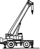 Figure A.1 — Industrial mobile crane |
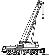 Figure A.2 — Mobile crane with telescopic jib |
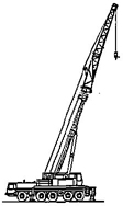 Figure A.3 — Mobile crane with telescopic and fly jib |
|
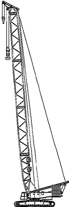 Figure A.4 — Mobile crane with luffing fly jib |
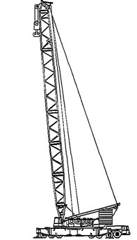 Figure A.5 — Mobile crane with lattice jib |
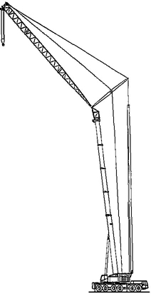 Figure A.6 — Crawler crane |
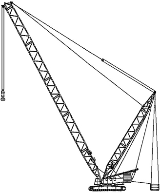 Figure A.7 — Mobile crane with additional counterweight |
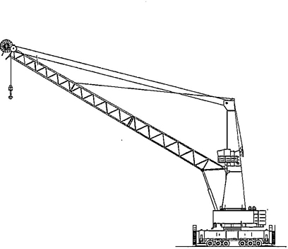 Figure A.8 — Mobile harbour crane |
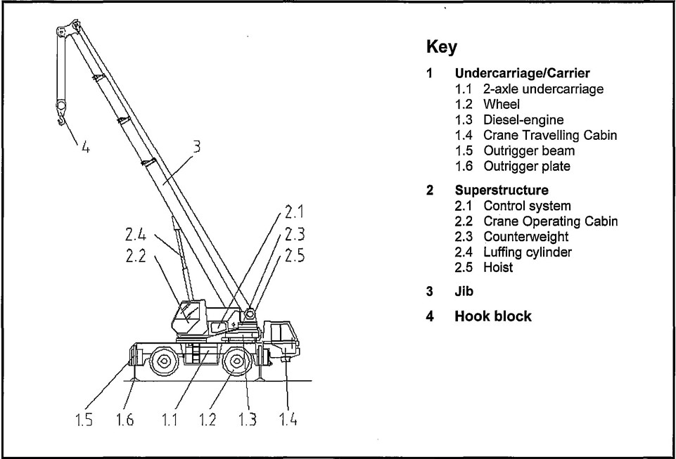
Figure B.1.1 — Examples of major parts
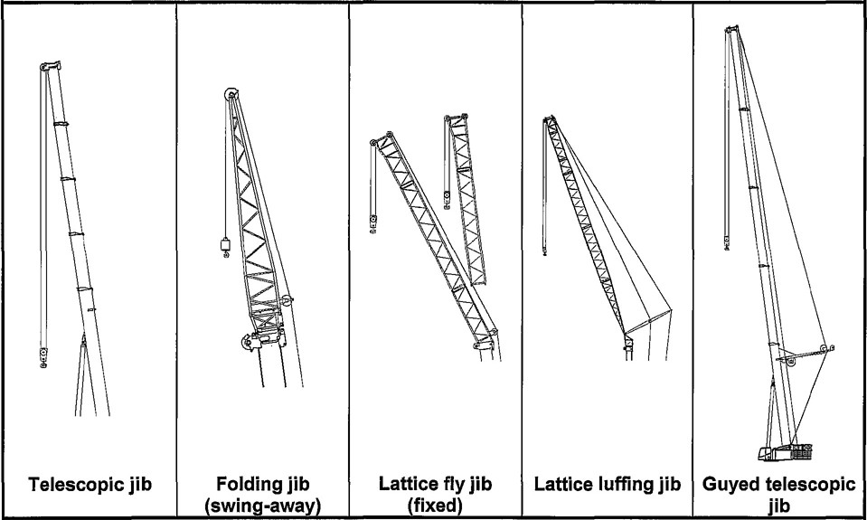
Figure B.1.2 — Examples of jibs and jib combinations
52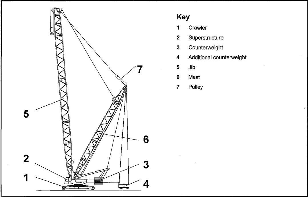
Figure B.2.1 — Examples of major parts
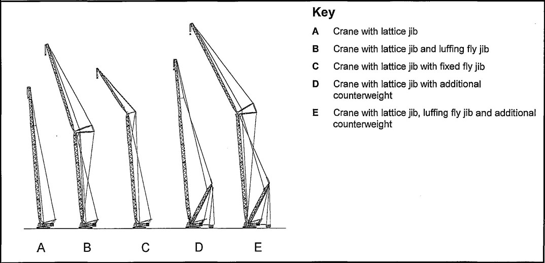
Figure B.2.2 — Examples of jibs and jib combinations
53This annex contains all the significant hazards, hazardous situations and events, as far as they are dealt with in the standard, identified by risk assessment as significant for this type of machinery and which require action to eliminate or reduce the risk.
The significant hazards are based upon EN 1050, the numbering follows the sequence of EN 1050, Table A.1. Also shown are the sub clause references to the safety requirements and/or protective measures in this standard. Before using this standard it is important to carry out a risk assessment of machine to check the hazards have been identified in the annex.
| No | Significant hazards and hazardous events | Annex A of EN ISO 12100-2: 2003 | EN ISO 12100 part 1 | EN ISO 12100 part 2 | Requirement clause(s) in this standard |
|---|---|---|---|---|---|
| 1 | Mechanical hazards due to −machine parts of workplaces − accumulation of energy inside the machinery |
1.3 1.5.3, 1.6.3 |
4.2 4.2 |
3.1, 3.2, 4 3.8, 6.2.2. |
4.1, 4.2 4.2.10 |
| 1.1 | Crushing hazard | 1.3 | 4.2.1 | 4.2.9 | |
| 1.2 | Shearing hazard | 1.3 | 4.2.1 | 4.2.2.3, 4.2.9 | |
| 1.4 | Entanglement hazard | 1.3 | 4.2.1 | 4.2.9 | |
| 1.5 | Drawing-in or trapping hazard | 1.3 | 4.2.1 | 4.2.9 | |
| 1.9 | High pressure fluid injection or ejection hazard | 1.3.2 | 4.2.1 | 3.8 | 4.2.10.2 |
| 2 | Electrical hazards | 1.5.1, 1.5.2, 1.6.3 | 4.3 | 3.9, 6.2.2 | 4.2.12, 6.2 |
| 3 3.1 |
Thermal hazards resulting in: Burns, scalds and other injuries by a possible contact of persons with objects or materials with an extreme high or low temperature, by flames or explosions and also by the radiation of heat sources |
1.5.5, 1.5.6, 1.5.7 |
4.4 |
4.2.9.5 |
|
| 3.2 | Damage to health by hot or cold working environment | 1.5.5 | 4.4 | 4.2.2.6 4.2.9.5 |
|
| 4 4.1 |
Hazards generated by noise, resulting in: Hearing loss (deafness), other physiological disorders (e.g. loss of balance, loss of awareness) |
1.5.8 |
4.5 |
3.2, 4 |
4.4.1, 4.4.2 |
| 4.2 | Interference with speech communication, acoustic signals, etc | 1.5.8 | 4.5 | 3.2, 4 | 4.2.5.2, 4.2.6.2, 4.4.1, 4.4.2 |
| 5 | Hazards generated by vibration | 1.5.9 | 4.6 | 3.2 | 4.2.4.4 |
| 7 7.1 |
Hazards generated by materials and substances (and their constituent elements) processed or exhausted by the machinery: Hazards from contact with or inhalation of harmful fluids, gases, mists, fumes and dusts |
1.1.3, 1.5.13, 1.6.5 |
4.8 |
3.3b, 3.4 |
4.2.2.6, 4.2.9.4 54 |
| 7.2 | Fire hazard or explosion hazard | 1.5.6, 1.5.7 | 4.8 | 3.4 | 4.5 |
| 8 | Hazards generated by neglecting ergonomic principles in machinery design as, e.g. hazards from: | ||||
| 8.1 | Unhealthy postures or excessive efforts | 1.1.2d, 1.1.5, 1.6.2, 1.6.4 | 4.9 | 3.6.1, 6.2.1, 6.2.3, 6.2.4, 6.2.6 |
4.2.2, 4.2.4, 4.2.5 |
| 8.2 | Inadequate consideration of hand-arm or foot-leg anatomy | 1.1.2d, 2.2 | 4.9 | 3.6.2 | 4.2.5 |
| 8.4 | Inadequate local lighting | 1.1.4 | 3.6.5 | 4.2.2.8, 4.3.2 | |
| 8.6 | Human error, human behaviour | 1.1.2d, 1.2.2, 1.2.5, 1.2.8, 1.5.4, 1.7 | 4.9 | 3.6, 3.7.8, 3.7.9,5, 6.1.1 |
4.1, 4.2.5, 4.2.6, 6, 7 |
| 8.7 | Inadequate design, location or identification of manual controls | 1.2.2 | 3.6.6, 3.7.8 |
4.2.5.2 | |
| 8.8 | Inadequate design or location of visual display units | 1.7.1 | 3.6.7, 5.2 | 4.2.6.2 | |
| 10 10.1 |
Unexpected start-up, unexpected overrun/overspeed: Failure/disorder of the control system |
1.2.7, 1.6.3 |
3.7, 6.2.2 |
4.2.5.1 |
|
| 10.2 | Restoration of energy supply after an interruption | 1.2.6 | 3.7.2 | 4.2.5.2, 4.2.5.3, 4.2.5.4 |
|
| 10.3 | External influences on electrical equipment | 1.2.1, 1.5.11, 4.1.2.8 | 3.7.11 | 4.2.12 | |
| 10.4 | Other external influences (gravity, wind, etc.) | 1.2.1 | 3.7.3 | 4.2.6.2.3 | |
| 14 | Failure of the control circuit | 1.2.1, 1.2.3, 1.2.4, 1.2.5, 1.2.7, 1.6.3 |
3.7, 6.2.2 | 4.2.5.1, 4.2.5.2, 4.2.5.4 |
|
| 15 | Errors of fitting | 1.5.4 | 4.9 | 3.7, 6.2.1 | 4.2.6, 4.2.9 |
| 18 | Loss of stability/overturning of machinery | 1.3.1 | 4.2.2 | 6.2.5 | 4.1.2, 4.1.3 |
| 19 | Slip, trip and fall of persons (related to machinery) | 1.5.15 | 4.2.3 | 6.2.4 | 4.2.9 |
| Additional hazards due to mobility | |||||
| 20 20.6 |
Additional hazards relating to the travelling function: Insufficient ability of machinery to be slowed down, stopped and immobilised |
3.3.3, 3.3.5 |
4.2.5.2, 4.2.8.2 |
||
| 21 21.1 |
Additional hazards linked to the work position Fall of persons during access to (at/from) the work position |
3.2.1, 3.2.3, 3.4.5, 3.4.7 |
4.2.9.3 |
||
| 21.2 | Exhaust gases/lack of oxygen at the work position | 3.2.1 | 4.2.9.4 | ||
| 21.3 | Fire | 3.2.1, 3.5.2 | 4.5.1, 4.5.2 | ||
| 21.4 | Mechanical hazards at the work position | 3.2.1, 3.4.3, 3.3.4, 3.4.2, 3.4.4, |
4.2.2.3 | ||
| 21.5 | Insufficient visibility from the work positions | 3.2.1 | 4.3.1 55 | ||
| 21.6 | Inadequate lighting | 3.1.2 | 4.2.2.8, 4.3.2 | ||
| 21.7 | Inadequate seating | 3.2.2 | 4.2.4 | ||
| 21.8 | Noise at the work position | 3.2.1 | 4.4, 5.3 | ||
| 21.9 | Vibration at the work position | 3.2.1, 3.2.2, 3.6.3 | 4.2.4.4 | ||
| 21.10 | Insufficient means for evacuation/emergency exit | 3.2.1 | 4.2.2.4 | ||
| 22 22.1 |
Additional hazards due to control system: Inadequate location of manual controls |
3.2.1, 3.3.1, 3.4.5 |
4.2.5.2 |
||
| 22.2 | Inadequate design of manual controls and their mode of operation | 3.2.1, 3.3.1, 3.3.3 | 4.2.5.2 | ||
| 23 | Additional hazards from handling the machine, lack of stability | 3.1.3 | 4.1.2, 4.1.3 | ||
| 24 | Additional hazards due to the power source; hazards from the engine and the batteries | 3.4.8, 3.5.1 | 4.2, 12.4 | ||
| 25 | Additional hazards from third persons, unauthorised start-up/use | 3.3.2 | 4.2.2.7, 4.2.5.3, 4.2.5.4 |
||
| 26 | Additional hazards from insufficient instructions for the driver/operator | 3.6 | 6 | ||
| Additional hazards due to lifting | |||||
| 27 27.1 |
Mechanical hazards: From load falls, collisions, machine tipping caused by: |
||||
| 27.1.1 | Lack of stability | 4.1.2.1 | 4.1.2.6 | ||
| 27.1.2 | Uncontrolled loading - overloading - overturning moments exceeded | 4.2.1.4, 4.3.3, 4.4.2a | 4.2.6 | ||
| 27.1.3 | Uncontrolled amplitude of movements | 4.1.2.6a, 4.2.1.3 | 4.1.2.6.4b, 4.2.5.1, 4.2.6.2.2, 4.2.6.2.3 |
||
| 27.1.4 | Unexpected/unintrended movement of loads | 4.1.2.6e | 4.2.5.2, 4.2.5.3, 4.2.5.4, 4.2.8 |
||
| 27.1.5 | Inadequate holding devices/accessories | 4.1.2.6e, 4.4.1 | 4.2.6.2.2 | ||
| 27.1.6 | Collision of more than one machine | 4.1.2.6b | 4.2.6.2.2 | ||
| 27.4 | From insufficient mechanical strength of parts | 4.1.2.3 | 4.1.2, 4.1.3 | ||
| 27.5 | From inadequate design of pulleys, drums | 4.1.2.4 | 4.1.2.5, 4.1.3.4 | ||
| 27.6 | From inadequate selection of chains, ropes, lifting and accessories and their inadequate integration into the machine | 4.1.2.4, 4.1.2.5, 4.3.1, 4.3.2 |
4.1.2.5, 4.1.3.4 | ||
| 27.8 | From abnormal conditions of assembly/testing/use/maintenance | 4.4.1, 4.4.2d | 4.1.2, 4.1.3, 5.2, 6.2, 6.3 |
||
| 28 | Electrical hazards from lightning | 4.1.2.8 | 6.2.2.2, 6.2.2.3 | ||
| 29 | Hazards generated by neglecting ergonomic principles, insufficient visibility from the driving position | 4.1.2.7, 4.4.2c | 4.3, 6.2.1, 6.2.2 | ||
In the case of crawler-, truck- and telescopic cranes the load is moved by hoisting (H), slewing (SI), luffing (Lu) (i.e. derricking), travelling (Tr) and telescoping (Te), see Figures D.1, D.2 and D.3.
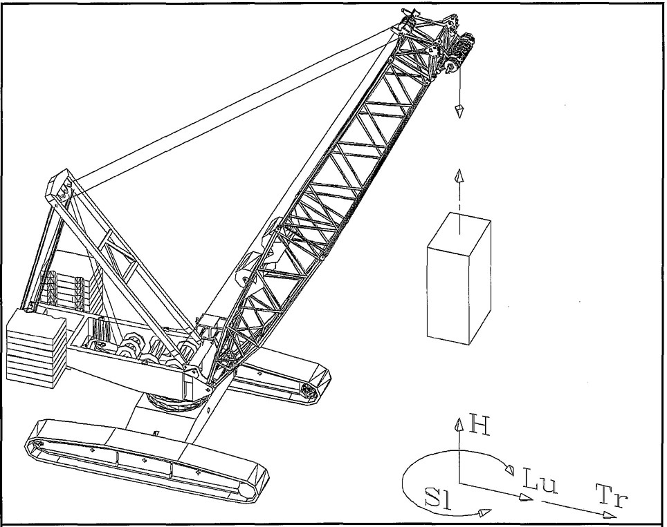
Figure D.1 — Crawler crane
57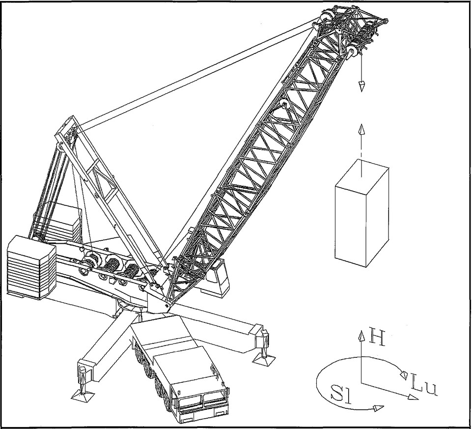
Figure D.2 — Crane on outriggers
58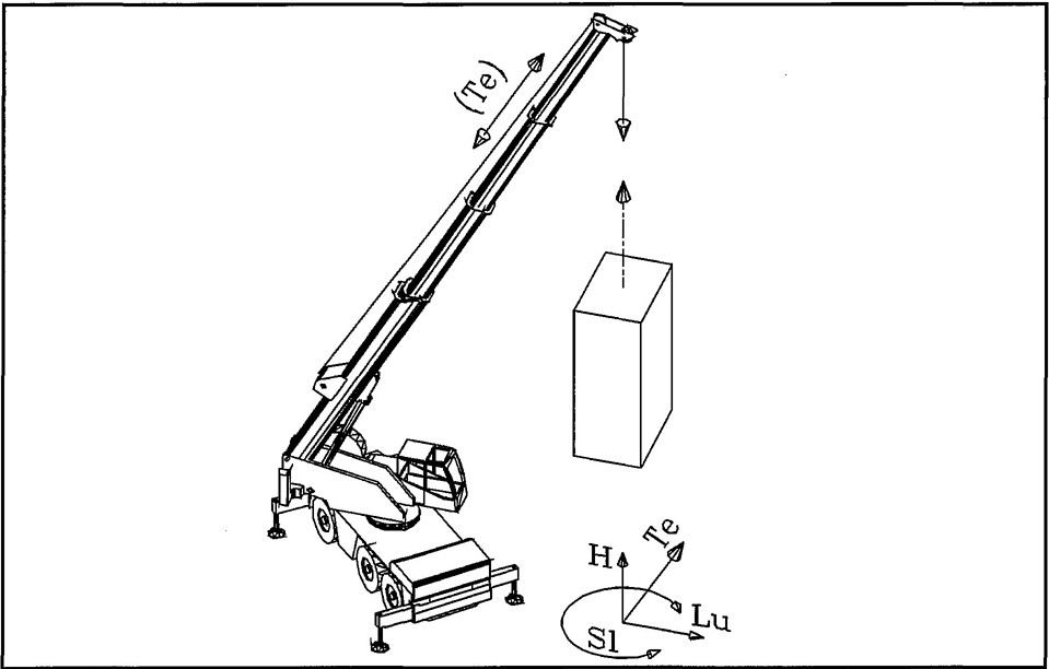
Figure D.3 — Telescopic crane on outriggers
The acceleration effects of these motions acting simultaneously on the crane depend on their control, the service conditions of the crane and whether the load is hoisted from the ground or if a suspended load is hoisted (see Table D.1).
If a mobile crane is designed to carry out simultaneous movements, the load effects of two of these movements shall be taken into account.
In case of hoisting a grounded load, only the effect of hoisting acceleration shall be considered.
| Hoisting a grounded load; Load combinations A1, B1, C1 |
Hoisting a suspended load; Load combinations A2-A4, B2-B4, C3 |
|---|---|
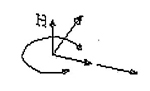 |
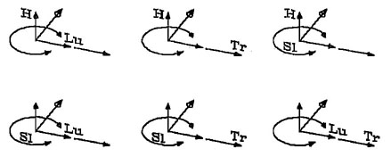 |
| NOTE Load combinations A, B, C are according to Table 3 of ISO 8686-1:1989. | |
In special cases the effects of three or more simultaneous movements can be considered, to be decided by the designer (see Table D.2).
| Hoisting a suspended load | Moving a suspended load |
|---|---|
 |
 |
This annex specifies dimensions and adjustments range for upright crane driver seats for use on mobile cranes.
for the crane driver’s seat and related adjustments shall be in accordance with Figure E.1 and Table E.1. All seat dimensions and adjustments (if provided) are referenced to the S.I.P as defined in EN 25353.
Nominal values of dimensions regarding seat elements, their mutual locations and adjustments shall be established on the basis of ergonomic requirements taking into consideration crane driver sizes (according to EN 23411:1988) from 5th percentile female through 95th percentile male.
Dimensions and adjustments other than those in this annex E may be used only if they provide better accommodation of the crane driver.
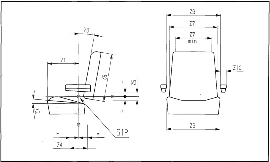
Figure E.1 — Seat dimensions (see Table E.1)
61| Dimension | Description | Key | Minimum | Nominal | Maximum |
|---|---|---|---|---|---|
| Z1 | Seat cushion length | 1 | 215 mm | 265 mm | 315 mm |
| Z2 | Seat cushion angle | 1, 2 | 5° | 10° | 15° |
| Adjustment | 1, 3 | +/−3° | +/−5° | − | |
| Z3 | Seat cushion width | 1 | 430 mm | − | 500 mm |
| Z4 | Forward/backward adjustment | 1, 4 | 100 mm | 150 mm | − |
| Z5 | Vertical adjustment | 1, 4 | 60 mm | − | − |
| Z6 | Back cushion height | 1, 5 | 150 mm | 400 mm | − |
| Z7 | Back cushion width | 1, 6 | 300 mm | 500 mm | − |
| Z8 | Back cushion angle | 1, 7 | 5° | 10° | 15° |
| (if applicable) | 1, 3 | +/−3° | +/−5° | − | |
| Z9 | Lateral gap between armrests | 1, 8 | 450 mm | 500 mm | 550 mm |
| Z10 | Armrest width | 1, 8 | 50 mm | 75 mm | − |
|
Key
|
|||||
Instead of an exact calculation of the load effect due to acceleration (see 4.1.2.6.4) the following simplified calculation procedure can be used. For the purpose of the simplified calculation procedure it can be assumed that the crane is operating on a level surface if the capacity charts permit up to 1 % gradient only.
The calculation shall show that the tipping angle for all rated capacities in all configurations slewed in the least stable direction is greater than or equal to the given minimum tipping angle (see Table F.1).
The tipping angle is indicated in Figure F.1.
To fix the height of the centre of gravity of the loaded crane the load shall be considered to be concentrated at the axle of the top sheaves of the jib.
| crane configuration/condition | min. tipping angle |
|---|---|
| on outriggers/crawlers in stationary condition | 4,0° |
| on wheels (tyres) in stationary condition | 4,5° |
| on crawlers/wheels (tyres) when travel speed up to 0,4 m/s is permissible | 4,5° |
| on crawlers/wheels (tyres) when travel speed greater than 0,4 m/s is permissible | 5,0° |
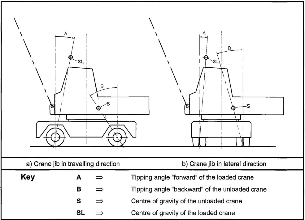
Figure F.1—Crane jib in travelling and in lateral direction
64This noise test code specifies all the information necessary to carry out efficiently and under standardized conditions the determination, declaration and verification of the noise emission characteristics of mobile cranes. It specifies the noise emission measurement methods that are available and the configuration and conditions that shall be used for the test.
Noise emission characteristics include emission sound pressure levels at workstations and the sound power level. The determination of these quantities is necessary for:
— manufacturers to declare the noise emitted;
— comparing the noise emitted by mobile cranes on the market;
— purposes of noise control at source at the design stage.
The use of this noise test code ensures the reproducibility of the determination of the noise emission characteristics within specified limits determined by the grade of accuracy of the basic noise measurement method used. Noise measurement methods of grade 2 are allowed by this standard.
This annex incorporates by dated or undated reference provisions from other publications. These normative references are cited at the appropriate places in the annex, and the publications are listed hereafter. For dated references, subsequent amendments to or revisions of any of these publications apply to this annex only when incorporated in it by amendment or revision. For undated references the latest edition of the publication referred to applies (including amendments).
EN ISO 4871, Acoustics—Declaration and verification of noise emission values of machinery and equipment (ISO 4871:1996).
Definitions of acoustical terms are given in the basic standards (see G.1.2).
This noise test code applies to all mobile cranes covered by this standard. The determination of sound power level (LWA) and emission sound pressure level(LpA) shall be carried out with the same test conditions.
Any modification to noise generating components shall result in a new series of measurements.
65The A-weighted sound power level of the mobile crane shall be determined using the basic standard EN ISO 3744, except with regard to the number and location of microphones (see G.1.5.3).
The measurement surface shall be a hemisphere, the radius of which shall be preferably 16 m. Other radii according to EN ISO 3744 shall be used if the crane does not fit into the 16 m hemisphere.
The mobile crane is installed so that geometric centre of the engine that drives the crane motions coincides with the radial centre of the hemisphere. The driving direction of the undercarriage is in the direction + × and the jib of the upper structure is in direction— ×. If the driving direction of the undercarriage is the same as the working direction of the jib (non slewing crane), the whole crane is aligned to direction— × (see Figure G.1).
If the mobile crane is equipped with only one engine for both driving and crane operation, the mobile crane is installed such that the middle point of the hemisphere is in the middle between the engine and the hoist(s) of the crane.
NOTE Sound power levels in frequency bands may also be determined using EN ISO 3744.
Microphone positions on the hemisphere shall be those indicated in Figure G.1.
NOTE The microphone positions given in Figure G.1 differ in number and location from those specified in EN ISO 3744. Experience with the determination of noise emission from mobile cranes shows that results obtained with the array of microphones of Figure G.1 do not differ significantly from those obtained with the microphone array specified in EN ISO 3744.
The measurement and calculation procedure in EN ISO 3744 shall be followed.
The A-weighted sound power level shall be determined for each part of the work cycle following the procedure of EN ISO 3744.
The A-weighted sound power level LWA cycle combined over the cycle shall be determined using the following equation:
— LWAi ⇒ is the A-weighted sound power level for part i of the work cycle.
— ai ⇒ is a percentage for each part i of the work cycle.
If telescoping is applicable, i=1 to 4, see G.1.8.2
a1 = 0,40 for a)
a2 = 0,25 for b)
a3 = 0,25 for c)
66a4=0,10 for d)
If telescoping is not applicable, i=1 to 3, see G.1.8.2
a1 = 0,40 for a)
a2 = 0,30 for b)
a3 = 0,30 for c)
The A-weighted emission sound pressure level at the operator position of a mobile crane shall be measured using EN ISO 11201.
NOTE Emission sound pressure levels at the operator position in frequency bands may also be measured using EN ISO 11201.
The operator position is that of a person seated at the crane operating controls in the crane operating cabin. This person shall wear standard working clothes.
Where a separate crane travelling cabin is provided this shall not be considered as the operator position.
The microphones shall be placed at 200 mm±20 mm on each side of the mid-plane of the head in the alignment of the eyes. They shall be placed perpendicularly to the mid-plane of the head and directed towards the front.
NOTE To facilitate the positioning of the microphones, it may be convenient to place them on a frame, to fix them to the safety helmet or to fit them onto a harness placed on the shoulders of the operator.
If the cabin is fitted with an air conditioning and/or ventilation system, then the readings shall be taken with all doors and windows closed and with the air conditioning and/or ventilation system in operation at 100% of their nominal working speed. If a high speed for rapid cooling is provided (not intended for normal operation) it shall be not in operation.
If it is anticipated that one can work in the cabin with doors and windows open, and there is no air conditioning and/or ventilation system fitted, then the readings shall be taken both with doors and windows closed and then with doors and windows open.
The maximum admissible wind speed is 8 m/s, measured at 1,5 m above ground level.
If the maximum allowable wind speed specified by the manufacturer of the microphone is exceeded, a wind shield shall be fitted to the microphone.
The measurement and calculation procedures in EN ISO 11201 shall be followed.
The maximum of the two measured A-weighted sound pressure level values (right ear or left ear) shall be retained.
67The A-weighted emission pressure level at the operator position, LpA to be determined shall be calculated from the values of the A-weighted emission sound pressure levels, LpAi measured for each part i of the work cycle using the following equation:
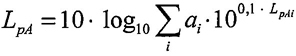
—LpAi⇒is the A-weighted sound pressure level for part i of the work cycle,
— the values of ai to be taken has given in G.1.5.4.
If the crane is equipped with outriggers, they shall be fully extended and the crane shall be levelled on its outrigger plates in mid position of possible support height.
The mobile crane to be tested shall be presented in its standard version as described by the manufacturer. The engine power considered for determining noise emission shall be the nominal power of the engine when used for crane motions. The crane shall be equipped with its maximum permitted counterweight mounted on the slewing structure.
Before carrying out any measurement, the engine and the hydraulic system of the mobile crane shall be brought to their normal working temperature following the instructions of the manufacturer and all relevant safety-related procedures given in the instruction manual shall be carried out.
If the mobile crane is equipped with several engines, the engine for the crane functions shall be used. The carrier engine shall be turned off.
If the engine of the mobile crane is fitted with a ventilator, it shall run during the test. If the ventilator can be operated at several speeds, the test shall be carried out with the ventilator running at the highest speed.
The mobile crane shall be measured under the following 3 or 4 operating conditions (a–c) or (a–d). Constant conditions for (a–d) are:
— engine speed at 3/4 of maximum speed specified for crane operation mode with a tolerance of ± 2 %.
— acceleration and deceleration at the maximum value without dangerous movements of the load or the hook block.
— motions at maximum possible speed as given in the instruction manual under the conditions given below.
NOTE If during the tests significant noise peaks occur, this should be reported.
a) Hoisting
68The mobile crane shall be loaded with a load which creates 50% of the maximum rope force. The test consists of the hoisting of the load and the immediately following lowering to the starting position. The length of the boom shall be chosen so that the full test lasts 15 s to 20 s.
b) Slewing
With the boom adjusted to an angle of 40°to50° to the horizontal and without load the upper carriage shall be slewed 90° to the left immediately followed by slewing back to the starting position. The jib shall be at its minimum length. The observation period shall be the time needed to carry out the working cycle.
c) Derricking
The test shall start with raising the shortest jib from the lowest working position immediately followed by the lowering of the jib to this original position. This movement shall be executed without load. The duration of the test shall be at least 20 s.
d) Telescoping (if applicable)
With the jib adjusted to an angle of 40°to50° to the horizontal, without load and the jib fully retracted, the telescoping cylinder for the first section only shall be extended together with the first section to its full length and immediately retracted together with the first section.
NOTE This can result in synchronous motion(s) of other sections.
The observation period shall be the time needed to carry out the working cycle.
The measurement uncertainty of the noise emission data provided by this noise test code is specific to the basic standard used. It is expressed in terms of the standard deviation of reproducibility. The grade of accuracy obtained is grade 2 (engineering) which is the preferred grade for noise declaration purposes.
The standard deviation of reproducibility of A-weighted sound power levels obtained using EN ISO 3744 is equal to 1,5 dB.
The standard deviation of reproducibility of A-weighted emission sound pressure levels at the operator position obtained using EN ISO 11201 is equal to 2,5 dB.
The information to be recorded is as required by the basic standards used, see G.1.2.
The information to be reported is as required by the basic standards used, see G.1.2. The contents of the test report shall be as shown in annex G.2.
The declaration of the noise emission values of a mobile crane is the responsibility of the manufacturer of the crane. It shall be done:
The noise declaration shall mention the fact that the noise emission values have been obtained according to this noise test code. In other cases, the noise declaration shall indicate clearly the deviations from this noise test code and/or from the basic standards used.
The noise declaration shall give the A-weighted sound power level for each part of the work cycle.
If undertaken, a verification shall be carried out by using the same configuration and operating conditions as used for the determination of the noise emission values.
NOTE Additional noise emission quantities such as sound power levels in frequency bands may also be given. In this case, care should be taken to avoid confusion between this additional information and the declared dual-number noise emission values.
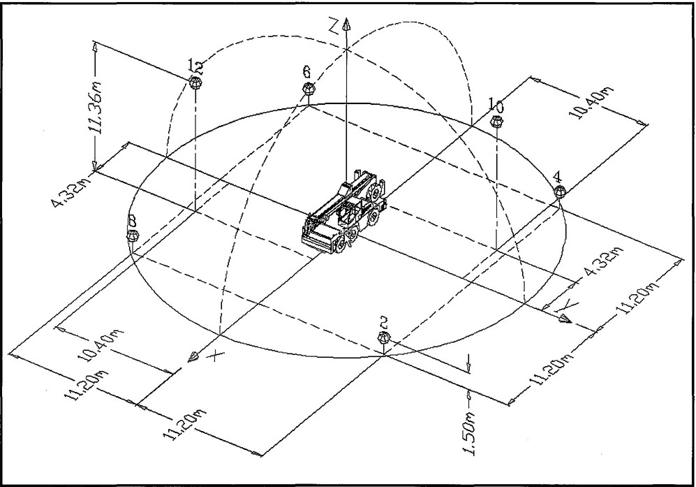
Figure G.1—Test conditions–exact position of the crane; in relation to the radial centre of the hemisphere see G.1.5.1 and G.1.5.2
70The following minimum data shall be given in each report, the format of the report is a proposal only:
| a) | Manufacturer reference | ||||||
| Name: | |||||||
| Address: | |||||||
| b) | Mobile crane reference | ||||||
| Manufacturer: | Type: | Version: | |||||
| Dimensions: L= | [m]; | B= | [m]; | H= | [m] | ||
| c) | Engine reference | ||||||
| Manufacturer: | Type: | ||||||
| Revs: | [1/min] (nominal value as declared) | ||||||
| Power: | [kW] (corresponding to speed; 80/1269/EEC) | ||||||
| Exhaust system | |||||||
| Manufacturer: | Type: | ||||||
| Air filter | |||||||
| Manufacturer: | Type: | ||||||
| d) | Test conditions | ||||||
| Indicate measurement points according to crane if other than in Figure G.1 | |||||||
| Ground type of test area: | |||||||
| Meteorological conditions | |||||||
| Weather general: | |||||||
| Temperature: | |||||||
| Barometric pressure: | |||||||
| Wind speed: | |||||||
| Relative humidity: | |||||||
| e) | Measuring instruments used | ||||||
| Manufacturer: | |||||||
| Type: | |||||||
| f) | Measurement results (see G.2.2) | ||||||
| Date: | |||||||
| Location: | |||||||
| Hoisting (up and down) |
Test | Sound pressure level at the measurement points |
Sound pressure in the operating cabin LpA |
||||||||
|---|---|---|---|---|---|---|---|---|---|---|---|
| 2 | 4 | 6 | 8 | 10 | 12 | LpAm | 1* | 2* | 3* | ||
| Load | No.1 | ||||||||||
| Radius | No.2 | ||||||||||
| No.3 | |||||||||||
| R = 16m | LWA=LpAm+10log(S/S0) = dB(A) | ||||||||||
| Derricking (up and down) |
Test | Sound pressure level at the measurement points |
Sound pressure in the operating cabin LpA |
||||||||
|---|---|---|---|---|---|---|---|---|---|---|---|
| 2 | 4 | 6 | 8 | 10 | 12 | LpAm | 1* | 2* | 3* | ||
| No.1 | |||||||||||
| No.2 | |||||||||||
| No.3 | |||||||||||
| R = 16 m | LWA = LpAm + 10log(S/S0) = d B(A) | ||||||||||
>
| Slewing (left and right) |
Test | Sound pressure level at the measurement points |
Sound pressure in the operating cabin LpA |
||||||||
|---|---|---|---|---|---|---|---|---|---|---|---|
| 2 | 4 | 6 | 8 | 10 | 12 | LpAm | 1* | 2* | 3* | ||
| Radius | No.1 | ||||||||||
| No.2 | |||||||||||
| No.3 | |||||||||||
| R = 16 m | LWA=LpAm+10log(S/S0) = dB(A) | ||||||||||
>
| Telescoping (in and out) |
Test | Sound pressure level at the measurement points |
Sound pressure in the operating cabin LpA |
||||||||
|---|---|---|---|---|---|---|---|---|---|---|---|
| 2 | 4 | 6 | 8 | 10 | 12 | LpAm | 1* | 2* | 3* | ||
| No.1 | |||||||||||
| No.2 | |||||||||||
| No.3 | |||||||||||
| R = 16 m | LWA=LpAm+10log (S/S0) = dB(A) | ||||||||||
| 1*: Doors and windows open 2*: Doors and windows closed without air conditioning and fan 3*: Doors and windows closed with air conditioning and fan |
|||||||||||
Calculation: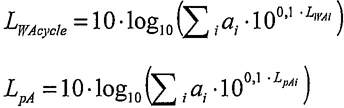 If telescoping is applicable, i = 1 to 4, see G.1.8.2 a1 = 0,40 for a) a2 = 0,25 for b) a3 = 0,25 for c) a4 = 0,10 for d) If telescoping is not applicable, i = 1 to 3, see G.1.8.2 a1 = 0,40 for a) a2 = 0,30 for b) a3 = 0,30 for c) Result: LWA cycle=———LpAi=——— |
>
| Signature | |
|---|---|
| Tested by (name): | Date and Place: |
| Organisation (name): | Signature: |
| Grade of Steel | Type | Yield Pointa [N/mm2] |
Tensile Strengthb [N/mm2] |
Shear Modulus [N/mm]2] |
Youngs Modulus of Elasticity [N/mm2] |
|---|---|---|---|---|---|
| Structural Steel | S 235 / (Fe 360) EN 10025 |
235 | 360 | 81 000 | 210 000 |
| Structural Steel | S 355 / (Fe 510) EN 10025 |
355 | 510 | ||
| Fine Grained Steel | S 460 / (FeE 460) EN 10113-2 |
460 | 570 | ||
| Fine Grained Steel | S 690 / (FeE 690) EN 10137-2 |
690 | 790 | ||
| Fine Grained Steel | S 890 / (FeE 885) EN 10137-2 |
890 | 940 | ||
| Fine Grained Steel | S 960 EN 10137-2 |
960 | 980 | ||
| a Standard value for thickness up to 50 mm b Minimum |
|||||
The information given is mandatory, the format of presentation is a proposal only.
| Technical Specification of Hoist gears/Derrick gears | |||
|---|---|---|---|
| General information | |||
| manufacturer | |||
| type (ordering code) | |||
| intended purpose | |||
| model | |||
| with brake/without brake | |||
| type of brake | |||
| use of brake | holding brake / dynamic brake | ||
| General data (dimensions, transmission ratio, drive) | |||
| dimensions see drawing no. | |||
| transmission ratio | iG | ||
| drive motor (manufacturer, type) | |||
| motor model | |||
| Information about duration of use and group classification | |||
| total duration of use (see annex A of FEM 1.001:1998, part 2) |
TH max | [h] | |
| group classification according to FEM 1.001:1998 | class of utilisation | ||
| spectrum class | |||
| mechanism group | |||
| Load effects | |||
| max. output torque (or max. drum torque) *1) | max TL | [kNm] | |
| average output torque *1) | TL,m | [kNm] | |
| output torque due to special loading condition: “test/load” *2) | TFg | [kN] | |
| max. output revolutions (or revolutions of drum) *3) | max n | [1/min] | |
| average output revolutions *3) | nm | [1/min] | |
| static torque of the brake *4) | TBR | [kNm] | |
| dynamic torque of the brake *5) | [kNm] | see enclosure | |
| Information about assembly and maintenance | |||
| admissible ambient temperatures | tmin | [°C] | |
| tmax | [°C] | ||
| type of gear oil | |||
| interval of oil change (operating hours) | [h] | ||
| Miscellaneous | |||
| mass (weight) (with oil/without oil) | [kg] | ||
| *1), *2), *3), *4), *5) Definitions/explanations see as follows. 75 | |||
The information given is mandatory, the format of presentation is a proposal only.
| Technical Specification of slewing gears | |||
|---|---|---|---|
| *1) | max T S | ⇒ | Maximum output torque — e. g. the output torque determined from slewing of the crane with load against in-service wind and against the maximum in-service permissible inclination and for this case intended slewing acceleration (see 2.5 and 2.6 of FEM 1.001:1998, Part 2). Occurring friction losses shall be taken in consideration. |
| T S,m | ⇒ | Average output torque calculated under consideration of the spectrum class according to T.2.1.3.3 of FEM 1.001:1998, Part 2. | |
 |
|||
| *2) | maxn | ⇒ | Maximum output revolutions |
| nm | ⇒ | Average output revolutions occurring at the same time to TS,m | |
| *3) | TBr | ⇒ | Required static holding torque of the brake — e. g. the holding torque due to in-service wind pressure on the crane and the load and due to the admissible in-service inclination. Special cases (e.g. the holding torque due to out-of-service wind and admissible out-of-service inclination) shall be considered additionally. |
| *4) | The dynamic braking torque results from both the maximum output torque (max TS) and the dynamic torque resulting from the required brake deceleration. Normally additional data is required to calculate and to produce a dynamic brake. Therefore this data shall be specified in an enclosure to the technical specification. The enclosure shall include the adequate explanations and comments. |
||
| General information | |||
| manufacturer | |||
| type (ordering code) | |||
| intended purpose | |||
| model | |||
| with brake / without brake | |||
| type of brake | |||
| use of brake | holding brake / dynamic brake | ||
| General data (dimensions, transmission ratio, drive) | |||
| dimensions see drawing no. | |||
| transmission ratio | iG | ||
| drive motor (manufacturer, type) | |||
| motor model | |||
| Information about duration of use and group classification | |||
| total duration of use (see annex A of FEM 1.001:1998, part 2) |
TH max | [h] | |
| group classification according to FEM 1.001:1998 | class of utilisation | ||
| spectrum class | |||
| mechanism group | |||
| Load effects | |||
| max. output torque*1) | max TS | [kNm] | |
| average output torque*1) | TS,m | [kNm] | |
| max. output revolutions*2) | maxn | [1/min] | |
| average output revolutions*2) | nm | [1/min] | |
| static torque of the brake*3) | TBr | [kNm] | |
| dynamic torque of the brake*4) | [kNm] | see enclosure | |
| Information about assembly and maintenance | |||
| admissible ambient temperatures | tmin | [°C] | |
| tmax | [°C] | ||
| type of gear oil | |||
| interval of oil change (operating hours) | [h] | ||
| Miscellaneous | |||
| mass (weight) (with oil/without oil) | [kg] | ||
| *1), *2), *3), *4) Definitions/explanations see as follows. 77 | |||
The information given is mandatory, the format of presentation is a proposal only.
| Technical Specification of Travel gears | |||
|---|---|---|---|
| *1) | The technical specification does not apply to travel gears (e.g. gear boxes or axle gears) of on-road mobile cranes. | ||
| NOTE Commercially purchased gearboxes for on-road use can be considered as acceptable for on site travel (with or without load). | |||
| *2) | max TTr | ⇒ | Maximum output torque according to 2.5 and 2.6 of FEM 1.001:1998, part 2, 2.6.4.2 case III applies normally. |
| TTr,m | ⇒ | Average output torque calculated under consideration of the spectrum class according to T.2.1.3.3 of FEM 1.001:1998, part 2. | |
 |
|||
| *3) | max n | ⇒ | Maximum output revolutions |
| nm | ⇒ | Average output revolutions occurring at the same time to TTr,m | |
| *4) | Loads which are not caused through drive torque but through exterior load effects (e. g. vertical supporting forces, wheel loads, horizontal transverse reactions due to travelling action) and acting on the gear or on parts of the gear shall be specified in an enclosure to the specification. The enclosure shall include adequate explanations and comments. | ||
| *5) | TBr | ⇒ | Required static holding torque of the brake — e. g. the required holding torque due to in-service wind pressure on the crane and the load and due to the passable inclination with load. Special cases (the holding torque due to out-of-service wind and the passable inclination without load) shall be considered additionally. |
| *6) | The dynamic braking torque results from the required brake deceleration. Normally additional data is required to calculate and to produce a dynamic brake. Therefore this data shall be specified in an enclosure to the specification. The enclosure shall include adequate explanations and comments. |
||
| General information | |||
| manufacturer | |||
| type(ordering code) | |||
| intended purpose *1) | |||
| model | |||
| with brake/without brake | |||
| type of brake | |||
| use of brake | holding brake/dynamic brake | ||
| General data (dimensions, transmission ratio, drive) | |||
| dimensions see drawing no. | |||
| transmission ratio | iG | ||
| drive motor (manufacturer, type) | |||
| motor model | |||
| Information about duration of use and group classification | |||
| total duration of use (see annex A of FEM 1.001:1998, part 2) |
TH max | [h] | |
| group classification according to FEM 1.001:1998 | class of utilisation | ||
| spectrum class | |||
| mechanism group | |||
| Load effects | |||
| max output torque *2) | max TTr | [kNm] | |
| average output torque *2) | TTr,m | [kNm] | |
| max. output revolutions *2) | max n | [1/min] | |
| average output revolutions *3) | nm | [1/min] | |
| additional loads *4) | see enclosure | ||
| static torque of the brake *5) | TBr | [kNm] | |
| dynamic torque of the brake *6) | [kNm] | see enclosure | |
| Information about assembly and maintenance | |||
| admissible ambient temperatures | tmin | [°C] | |
| tmax | [°C] | ||
| type of gear oil | |||
| interval of oil change (operating hours) | [h] | ||
| Miscellaneous | |||
| mass (weight) (with oil/without oil) | [kg] | ||
| *1), *2), *3), *4), *5), *6) Definitions/explanations see as follows. 79 | |||
The information given is mandatory, the format of presentation is a proposal only.
| Technical Specification of Hoist drums/ Derrick drums | |||
|---|---|---|---|
| *1) | e. g. ISO 4308-1, DIN 15061-2:1977. | ||
| *2) | According to the group classification of the mechanism belonging to the drum (see annex J.1). | ||
| *3) | See Table 1 of FEM 5.004:1994, case 1. The friction losses shall be considered. | ||
| *4) | Average data FR,m, nDr,m calculated considering the spectrum class according FEM 1.001:1998 part 2. | ||
 |
|||
| nDr,m ⇒ Average output revolutions occuring at the same time to FR,m | |||
| *5) | Maximum value max FR due to the special loading condition (during crane erection or dismantling, test load) that gives rise to the maximum stress in the drum. | ||
| General information | |||
| manufacturer | |||
| type of mechanism | hoist mechanism/derrick mechanism | ||
| delivery condition | finished product/moulded blank | ||
| drawing no. | |||
| type of drum | single drum/dual drum | ||
| max number of rope layers | |||
| type of groove thread | normal thread/parallel thread(Lebus system) | ||
| groove profile (standard used) *1) | |||
| Main dimensions | |||
| dimensions see drawing no. | |||
| rope diameter | dR | [mm] | |
| rope length (max, winding length) | IR | [m] | |
| nominal diameter of drum (pitch dia, related to middle of first layer) |
dDr | [mm] | |
| diameter of last rope layer (related to middle of rope) | dDr(n) | [mm] | |
| drum width (between the flanges) | bDr | [mm] | |
| outer diameter of flanges | dF1 | [mm] | |
| pitch of groove thread | t | [mm] | |
| Group classification of mechanism | |||
| group classification according to FEM 1.001:1998 *2) | class of utilisation | ||
| spectrum class | |||
| mechanism group | |||
| Load effects | |||
| nominal rope force *3) | FR | [kN] | |
| Data for determination of fatigue life *4) | |||
| average rope force | FR,m | [kN] | |
| average revolutions | nDr,m | [1/min] | |
| Data for checking for ultimate strength *5) | |||
| max. rope force due to special load case | max FR | [kN] | |
| Information about material and manufacturing process | |||
| manufacturing process | welding/casting | ||
| Material | |||
| Miscellaneous | |||
| mass (weight) (in delivery condition) | [kg] | ||
| *1), *2), *3), *4), *5) Definitions/explanations see as follows. 81 | |||
The information given is mandatory, the format of presentation is a proposal only.
| Technical Specification of Lifting Hooks | |||
|---|---|---|---|
| *1) e. g.: single hook DIN 15401, Part 1:1982 and Part 2:1983–GSN–M | |||
| *2) e. g.: DIN 15400:1990 | |||
| *3) e. g.: metric thread ISO 261, knuckle thread DIN 15403:1969. | |||
| *4) e. g.: drop forged, hammer forged. | |||
| General Information | |||
| manufacturer | |||
| ordering code *1) | |||
| form of hook | single hook/ramshorn hook | ||
| boss for safety catch | with boss/without boss | ||
| Lifting capacity, Classification | |||
| nominal lifting load | LH | [t] | |
| lifting load in accordance to (standard used) *2) | |||
| strength class/grade *2) | |||
| mechanism group (ISO 4301-1) | |||
| Dimensions | |||
| standard of hook dimensions | |||
| type and standard of shank thread *3) | |||
| Information about manufacturing process and material | |||
| manufacturing process *4) | |||
| material | |||
| Miscellaneous | |||
| marking (standard used) | |||
| certificate (standard used) | |||
| mass (weight) | [kg] | ||
| *1), *2), *3), *4) Definitions/explanations see as follows | |||
The information given is mandatory, the format of presentation is a proposal only.
| Technical Specification of Sheaves | |||
|---|---|---|---|
| *1) e. g. ISO 4308-1, DIN 15061-1 | |||
| *2) see 2.1.4 of FEM 1.001:1998, part 2 | |||
| *3) see Table 1 of FEM 5.004:1994, case 1. Friction losses have to be considered. | |||
*4) Average data FR,m, γR,m, calculated under consideration of the spectrum class according to FEM 1.001:1998, part 2. with:  |
|||
| *5) Maximum values of max FR, max γR from special load case (during erection, dismantling or test load), that gives rise to the maximum stress in the sheave. | |||
| *6) Special requirements for plastic sheaves (e.g. interference fit of hub bore, minimal diameter of hub bore, minimal hub width) shall be specified in an enclosure to the specification or in an general agreement. | |||
| General information | |||
| manufacturer | drawing no. | ||
| groove profile (standard used) *1) | |||
| bearing application | plain bearing / roller bearing (bearings are not included in the scope of supply) | ||
| no. and type of bearings | |||
| Main dimensions | |||
| dimensions see drawing no. | |||
| rope diameter (nominal) | dR | [mm] | |
| loop angle | βR | [°] | |
| nominal diameter (related to center rope) | dSh,1 | [mm] | |
| diameter of hub bore | dSh,2 | [mm] | |
| hub width | lSh,2 | [mm] | |
| axle diameter | dSh,3 | [mm] | |
| Information about duration of use and group classification | |||
| max. number of stress cycles | nC | ||
| group classification according to FEM 1.001:1998 *2) | class of utilisation | ||
| spectrum class | |||
| mechanism group | |||
| Load effects | |||
| nominal rope force *3) | FR | [kN] | |
| Data for determination of strength *4) | |||
| average rope force | FR,m | [kN] | |
| average diagonal pull angle | γR,m | [°] | |
| average revolutions | nSh,m | [1/min] | |
| Data for checking the safety margin against ultimate strength *5) | |||
| max. rope force due to special load case | max FR | [kN] | |
| max. diagonal pull angle | max γR | [°] | |
| Material specification | |||
| kind of material *6) | steel/plastic/light metal | ||
| Miscellaneous | |||
| mass (weight) | [kg] | ||
| *1), *2), *3), *4), *5), *6) Definitions/explanations see as follows. 84 | |||
The information given is mandatory, the format of presentation is a proposal only.
| Technical Specification of Hook Blocks | |||
|---|---|---|---|
| *1) see Figure K.3.1 | |||
| *2) Minimum requirements for technical specification of lifting hooks see annex K.1 | |||
| *3) Minimum requirements for technical specification of sheaves see annex K.2 | |||
| *4) Agreement between the designer of the crane and the manufacturer of the hook block | |||
| General Information | |||
| manufacturer | |||
| dimensions see drawing no. | |||
| model *1) | single/double/multiple hook block | ||
| Lifting capacity, Classification | |||
| nominal lifting load | LH | [t] | |
| mechanism group (ISO 4301-1) | |||
| Information about ropes and no. of falls *1) | |||
| rope diameter | dR | [mm] | |
| max. number of ropes | |||
| max. number of falls | |||
| Lifting hook | |||
| technical specification of lifting hook *2) | |||
| Sheaves | |||
| number of sheaves *1) | |||
| technical specification of sheaves *3) | |||
| Miscellaneous | |||
| marking (agreement) *4) | |||
| certificate (agreement) *4) | |||
| mass (weight) | [kg] | ||
| *1), *2), *3), *4) Definitions/explanations see as follows | |||
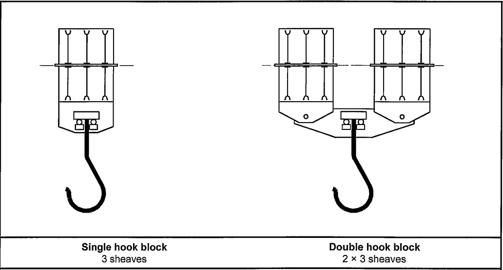
Figure K.3.1 — Model of hook blocks (examples):
87The information given is mandatory, the format of presentation is a proposal only.
| Technical Specification of Hydraulic Cylinders | |||
|---|---|---|---|
| *1) e. g. outrigger cylinder (vertical, horizontal), luffing cylinder, telescoping cylinder, jib restraining cylinder, suspension cylinder, axle blocking cylinder, hydro-accumulator cylinder, working cylinder (general). | |||
| *2) e.g. pulling cylinder, pushing cylinder, differential cylinder. | |||
| General information | |||
| manufacturer | |||
| type (ordering code) | |||
| dimensions see drawing no. | |||
| intended purpose *1) | |||
| model *2) | |||
| Main dimensions (see drawing) | |||
| piston diameter | d1 | [mm] | |
| piston rod diameter | d2 | [mm] | |
| outer diameter | d3 | [mm] | |
| stroke length | h | [mm] | |
| overall length (retracted) | l0 | [mm] | |
| Information about duration of use and group classification | |||
| max. number of stress cycles | nC | ||
| group classification according to FEM 1.001:1998 | class of utilisation | ||
| spectrum class | |||
| mechanism group | |||
| Load effects (permissible loads, pressures, piston speed) | |||
| maximum operating pressure, pressure, piston side | Pc,1 | [bar] | |
| maximum operating pressure, piston rod side | Pc,3 | [bar] | |
| test pressure, piston side | PT,1 | [bar] | |
| test pressure, piston rod side | PT,3 | [bar] | |
| max. pushing force (retracted) | Fc,1 | [N] | |
| max. pushing force (extended) | Fc,2 | [N] | |
| max. pulling force | Fc,3 | [N] | |
| max. piston speed | vc | [m/s] | |
| Information about assembly and maintenance | |||
| admissible ambient temperatures | tmin | [°C] | |
| tmax | [°C] | ||
| medium (type of hydraulic fluid) | |||
| Miscellaneous | |||
| type of corrosion prevention (e.g. piston rode) | |||
| layer thickness | [μm] | ||
| mass (weight) (with/without fluid) | [kg] | ||
| *1), *2) Definitions/explanations see as follows 88 | |||
The information given is mandatory, the format of presentation is a proposal only.
| Technical Specification of Slew Rings | |||
|---|---|---|---|
| 1* The load limiting diagram (load moment as a function of axial load) shall include curves showing at least the permissible static and dynamic loads for slew ring and rollers/balls and permissible static and dynamic loads for bolt/screw connections, test load curve. | |||
| 2* e.g.: Ball type slew ring, roller type slew ring (single row bearing, triple row bearing etc.) | |||
| 3* e.g.: Shank bolts–ISO 4014:1999 | |||
| General information | |||
| manufacturer | drawing no.(manufacturer) | ||
| load limiting diagram no. *1) | |||
| type / model *2) | |||
| General dimensions | |||
| outer diameter | |||
| inner diameter | |||
| height(between the connecting surfaces) | |||
| Gear tooth geometry | |||
| type of gearing | internal gear / external gear | ||
| no. of teeth | |||
| diametrical pitch | |||
| tooth width | |||
| profile correction (x.m) | |||
| Fixing bolts/screws for superstructure | |||
| no. of bolts/screws | i | ||
| type of bolts/screws (standard used) *3) | |||
| bolt/screw thread size | |||
| strength class | |||
| assembly method | torque controlled/hydraulic tension method | ||
| mounting torque | MA | [Nm] | |
| tension force | FA | [kN] | |
| Fixing bolts/screws for carrier | |||
| no. of bolts/screws | i | ||
| type of bolts/screws (standard used) *3) | |||
| bolt thread size | |||
| strength class | |||
| assembly method | torque controlled/hydraulic tension method | ||
| mounting torque | MA | [Nm] | |
| tension force | FA | [kN] | 90 |
| Admissible loads (additional information for load limiting diagram) | |||
| permissible tangential force of gearing | max FU | [kN] | |
| Permissible radial force | max FR | [kN] | |
| Miscellaneous | |||
| type of grease (standard used) | |||
| mass (weight) | [kg] | ||
| *1),*2),*3) Definitions/explanations see as follows. | |||
The objective of this annex is to prove theoretically and/or by experiment that a mobile crane, taking into account the expected service conditions agreed between the user, designer and/or manufacturer, as well as the states during erection, dismantling and transport, has been designed to be in conformity with the safety requirements to prevent mechanical hazards.
The theoretical proof of competence is based on the comparison of the limit states with calculated nominal load effects. The calculations for the proof of competence of (steel) structures shall allow either the method of permissible stresses (see L.2.2) or the method of partial safety coefficients and limiting stresses (see L.2.3) – where appropriate.
The experimental proof of competence shall provide a systematic, non-destructive procedure for determining the stresses in structures under equivalent static loads and load combinations.
The proof of competence for rigid body stability shall prevent any lack of stability of the crane in-and out-of-service, during its intended use, erection and dismantling.
By evaluation of the load effects and the definition of the limit states of the crane structure and its components the proof of competence shall be carried out to show adequate safety for any hazard due to loss of mechanical strength and/or loss of stability.
The determination of stresses, which depend on the loading condition and the type of analysis, shall not exceed the permissible stresses or the limiting stresses. In addition the required safety margins shall be fulfilled.
These required minimum safety margins in comparison between the maximum values of load effects established by calculation or experiment and the limit states are given in the following sub-clauses.
The theoretical proof of competence shall be made in accordance with FEM5.004:1994. The experimental proof of competence is covered by L.6.
The calculation and analysis for the proof of competence shall be made according to either the method of permissible stresses or the method of partial safety coefficients and limiting stresses. The selection of the method to be applied shall be made in accordance with clause 6 of FEM 5.004:1994.
The minimum required safety factors for structural components and for welds shall be taken from Tables 3 and 4 of FEM 5.004:1994.
The partial safety coefficients shall be taken from Table 5 of FEM 5.004:1994.
The minimum required safety factors for structural components and for welds shall be taken from Tables 6 and 7 of FEM 5.004:1994.
92The theoretical proof of competence shall be made with the same minimum required safety factors as for steel structures. Additional effects of non-metallic materials, e.g. long time behaviour, environmental influences (e.g. temperature, humidity) and ageing of plastic materials, shall be considered according to the state of art.
The experimental proof of competence is covered by L.6.
The theoretical proof of competence shall be made in accordance with the following subclauses. The experimental proof of competence is covered by L.6.
A written agreement between the manufacturer of the crane and the manufacturer of the component shall state clearly that the loading, environmental and service conditions (classification) are permissible during the total intended lifetime of the component.
The general design principles and safety margins shall be in accordance with FEM 1.001:1998 Part 4.
The minimum requirements for the written agreements are laid down in the relevant parts of annex J.
The proof of competence for ropes shall be made as a comparison of the actual safety factor – calculated by the load (increased by adequate factors due to friction) and the limit state for the rope (minimum breaking load)–with the minimum values for Zp given by ISO 4308-2.
For test load cases of special configurations (e. g. crane with additional counterweight – see Figure A.7) the minimum Zp value for luffing/derricking ropes shall not be less than 3.35.
The proof of competence for the end termination of a rope system shall be as follows:
a) The end termination of running ropes shall permit a minimum breaking load not less than 80% of the minimum breaking load of the rope itself;
b) The end termination of stationary ropes shall permit a minimum breaking load not less than 90% of the minimum breaking load of the rope itself;
c) In any case where the minimum breaking load of a rope system is reduced by the end termination, the safety factors for the rope systems shall not be less than the values for erection given in Table 1 of ISO 4308-2:1988;
d) The attachment of the rope to the hoist drum shall be in a way that 2.5 times the rope force can be taken up taking into account the friction of the rope remaining on the hoist drum. The friction factor between the rope and the hoist drum shall be taken as μ=0,1.
The proof of competence for chains shall be done either by the manufacturer of the chains or by a simplified calculation by the manufacturer of the crane.
In the case of the simplified calculation, the minimum breaking load of a chain shall not be less than 4 times the nominal load in the chain without consideration of friction losses, under the loading conditions according to group classification A1 of ISO 4301-1.
93The end termination shall be in accordance with 4.1.1 of FEM 1.001:1998 part 4.
The proof of competence for other components shall be made in accordance with general design principles. The minimum requirements for the written agreements between the manufacturer of the components and the manufacturer of the crane are laid down in annex K.
The proof of competence for rigid body stability shall verify that the stabilising moment of the crane is greater or equal than the overturning moment under static and/or dynamic conditions as specified in 4.1.2.6.
This proof shall either be done by theoretical proof of competence (calculation according to ISO 4305 verified by tests according to ISO 4310) or by an experimental proof of competence, see L.6.
The experimental proof of competence to determine the stresses induced in the crane structure(s) and load bearing components requires a systematic, non-destructive procedure under specified conditions. The procedure shall be in accordance with ISO/CD 11662-2. The required minimum safety margins for different load combinations shall be in accordance with L.2.
The experimental proof of competence of rigid body stability of the crane as a whole according to ISO 11662-1 shall be verified by, as a minimum, the stability tests as specified by ISO 4310. Additional experiments shall be made for backward stability and tipping due to acceleration (see annex F) showing that the same level of safety as for calculation is achieved. When testing the stability of the crane, the limits of structural strength and other limits of components shall be observed.
94The test shall be conducted on a surface offering good adhesion (e. g. concrete, asphalt).
The crane shall be unloaded and in normal travel order.
The crane shall be driven from straight ahead into a spiral with a turning radius as given in Table M.1 at a speed of 10 km/h. The steering effort shall be measured at the nominal radius of the steering control. At least one measurement of each steering movement shall be made to the right and to the left.
The test shall be carried out for both the infact steering and the steering with a simulated failure (e. g. failure of power assistance).
NOTE If the steering is purely mechanical, simulated failure test does not apply. In the EU-Directive 70/311/EEC mechanical failures are not specified.
Steering control efforts shall not exceed the values given in Table M.1.
| Steering intact | Steering with a simulated failure | ||
|---|---|---|---|
| Maximum effort (daN) |
Turning radius (m) |
Maximum effort (daN) |
Turning radius (m) |
| a or full lock if 15 m is not possible | |||
| 30 | 15a | 60 | 30 |
| Beaufort Grade | 3 | 4 | 5a | 5 | 6 | 7a | 7 | 8 | 9 | 10 | |
|---|---|---|---|---|---|---|---|---|---|---|---|
| a | In-service wind: | ||||||||||
| 1 light = 10.1 [m/s] ⇒ for z = 10[m] ⇒ q(z) = 125[N/m2] |
|||||||||||
| 2 normal = 14,3 [m/s] ⇒ for z = 10[m] ⇒ q(z) = 250[N/m2] |
|||||||||||
| b | Upper Beaufort Limit | ||||||||||
| [m/s]b |
5,4 | 7,9 | 10,1 | 10,7 | 13,8 | 14,3 | 17,1 | 20,7 | 24,4 | 28,4 | |
| z[m] | ν(z) [m/s] | ||||||||||
| 10 | 7,6 | 11,1 | 14,1 | 15,0 | 19,3 | 20,0 | 23,9 | 29,0 | 34,2 | 39,8 | |
| 20 | 8,1 | 11,9 | 15,2 | 16,1 | 20,7 | 21,5 | 25,7 | 31,1 | 36,6 | 42,7 | |
| 30 | 8,5 | 12,4 | 15,8 | 16,8 | 21,6 | 22,4 | 26,8 | 32,4 | 38,2 | 44,5 | |
| 40 | 8,7 | 12,8 | 16,3 | 17,3 | 22,3 | 23,1 | 27,6 | 33,4 | 39,4 | 45,8 | |
| 50 | 8,9 | 13,1 | 16,7 | 17,7 | 22,8 | 23,6 | 28,3 | 34,2 | 40,3 | 46,9 | |
| 60 | 9,1 | 13,3 | 17,0 | 18,0 | 23,3 | 24,1 | 28,8 | 34,9 | 41,1 | 47,9 | |
| 70 | 9,3 | 13,5 | 17,3 | 18,3 | 23,6 | 24,5 | 29,3 | 35,5 | 41,8 | 48,7 | |
| 80 | 9,4 | 13,7 | 17,6 | 18,6 | 24,0 | 24,8 | 29,7 | 36,0 | 42,4 | 49,4 | |
| 90 | 9,5 | 13,9 | 17,8 | 18,8 | 24,3 | 25,1 | 30,1 | 36,4 | 42,9 | 50,0 | |
| 100 | 9,6 | 14,1 | 18,0 | 19,1 | 24,6 | 25,4 | 30,4 | 36,9 | 43,4 | 50,6 | |
| 110 | 9,7 | 14,2 | 18,2 | 19,2 | 24,8 | 25,7 | 30,8 | 37,2 | 43,9 | 51,1 | |
| 120 | 9,8 | 14,3 | 18,3 | 19,4 | 25,1 | 25,1 | 31,1 | 37,6 | 44,3 | 51,6 | |
| 130 | 9,9 | 14,5 | 18,5 | 19,6 | 25,3 | 26,2 | 31,3 | 37,9 | 44,7 | 52,0 | |
| 140 | 10,0 | 14,6 | 18,7 | 19,8 | 25,5 | 26,4 | 31,6 | 38,2 | 45,1 | 52,5 | |
| 150 | 10,0 | 14,7 | 18,8 | 19,9 | 25,7 | 26,6 | 31,8 | 38,5 | 45,4 | 52,9 | |
| 160 | 10,1 | 14,8 | 18,9 | 20,1 | 25,9 | 26,8 | 32,1 | 38,8 | 45,7 | 53,2 | |
| 170 | 10,2 | 14,9 | 19,1 | 20,2 | 26,0 | 27,0 | 32,3 | 39,1 | 46,0 | 53,6 | |
| 180 | 10,3 | 15,0 | 19,2 | 20,3 | 26,2 | 27,1 | 32,5 | 39,3 | 46,3 | 53,9 | |
| 190 | 10,3 | 15,1 | 19,3 | 20,4 | 26,4 | 27,3 | 32,7 | 39,5 | 46,6 | 54,2 | |
| 200 | 10,4 | 15,2 | 19,4 | 20,6 | 26,5 | 27,4 | 32,8 | 39,8 | 46,9 | 54,6 | |
>
| [m/s]: |
Mean wind speed at 10 m elevated (upper limit of Beaufort grade) over a period of 10 minutes |
| z [m]: | Elevation above even ground |
| ν(z) [m/s]: | 3-second wind gust speed acting at elevation z and decisive for calculations |
| q(z) [N/m2]: | quasi-static impact pressure acting at elevation z and calculated based on ν(z), see annex N.2 |
| Beaufort Grade | 3 | 4 | 5a | 5 | 6 | 7a | 7 | 8 | 9 | 10 | |
|---|---|---|---|---|---|---|---|---|---|---|---|
| [m/s]b |
5,4 | 7,9 | 10,1 | 10,7 | 13,8 | 14,3 | 17,1 | 20,7 | 24,4 | 28,4 | |
| z[m] | q(z) [N/m2] | ||||||||||
| 10 | 35,7 | 76,5 | 125,0 | 140,3 | 233,3 | 250,0 | 358,2 | 524,9 | 729,3 | 988,0 | |
| 20 | 41,1 | 88,0 | 143,8 | 161,4 | 268,5 | 287,7 | 412,2 | 604,1 | 839,4 | 1 137,1 | |
| 30 | 44,7 | 95,7 | 156,4 | 175,5 | 292,0 | 312,9 | 448,3 | 657,0 | 912,8 | 1 236,6 | |
| 40 | 47,5 | 101,6 | 166,1 | 186,4 | 310,1 | 332,3 | 476,2 | 697,8 | 969,6 | 1 313,5 | |
| 50 | 49,8 | 106,5 | 174,2 | 195,5 | 325,1 | 348,4 | 499,2 | 731,5 | 1 016,4 | 1 376,9 | |
| 60 | 51,8 | 110,8 | 181,0 | 203,2 | 338,0 | 362,2 | 519,0 | 760,5 | 1 056,6 | 1 431,4 | |
| 70 | 53,5 | 114,5 | 187,1 | 210,0 | 349,3 | 374,3 | 536,4 | 786,0 | 1 092,1 | 1 479,5 | |
| 80 | 55,0 | 117,8 | 192,6 | 216,1 | 359,5 | 385,2 | 552,0 | 808,9 | 1 123,9 | 1 522,6 | |
| 90 | 56,5 | 120,8 | 197,5 | 221,7 | 368,8 | 395,1 | 566,2 | 829,7 | 1 152,8 | 1 561,8 | |
| 100 | 57,8 | 123,6 | 202,1 | 226,8 | 377,3 | 404,3 | 579,3 | 848,9 | 1 179,5 | 1 597,9 | |
| 110 | 59,0 | 126,2 | 206,3 | 231,6 | 385,2 | 412,7 | 591,4 | 866,7 | 1 204,2 | 1 631,3 | |
| 120 | 60,1 | 128,6 | 210,3 | 236,0 | 392,6 | 420,6 | 602,8 | 883,3 | 1 227,2 | 1 662,6 | |
| 130 | 61,2 | 130,9 | 214,0 | 240,2 | 399,5 | 428,1 | 613,4 | 898,8 | 1 248,9 | 1 691,9 | |
| 140 | 62,2 | 133,1 | 217,5 | 244,1 | 406,0 | 435,1 | 623,4 | 913,6 | 1 269,3 | 1 719,6 | |
| 150 | 63,1 | 135,1 | 220,8 | 247,8 | 412,2 | 441,7 | 632,9 | 927,5 | 1 288,7 | 1 745,9 | |
| 160 | 64,0 | 137,0 | 224,0 | 251,4 | 418,1 | 448,0 | 642,0 | 940,8 | 1 307,1 | 1 770,8 | |
| 170 | 64,9 | 138,9 | 227,0 | 254,8 | 423,7 | 454,1 | 650,6 | 953,4 | 1 324,7 | 1 794,7 | |
| 180 | 65,7 | 140,6 | 229,9 | 258,0 | 429,1 | 459,8 | 658,9 | 965,5 | 1 341,6 | 1 817,5 | |
| 190 | 66,5 | 142,3 | 232,6 | 261,1 | 434,3 | 465,4 | 666,8 | 977,2 | 1 357,7 | 1 839,3 | |
| 200 | 67,3 | 144,0 | 235,3 | 264,1 | 439,3 | 470,7 | 674,5 | 988,3 | 1 373,2 | 1 860,4 | |
| a | In-service wind | ||||||||||
| 1 light = 10,1 [m/s] ⇒ for z = 10 [m] ⇒ q(z) = 125 [N/m2] |
|||||||||||
| 2 normal = 14,3 [m/s] ⇒ for z = 10 [m] ⇒ q(z) = 250 [N/m2] |
|||||||||||
| b | Upper Beaufort Limit | ||||||||||
>
| [m/s]: |
Mean wind speed at 10 m elevated (upper limit of Beaufort grade) over a period of 10 minutes. |
| z[m]: | Elevation above even ground |
| ν(z) [m/s]: | 3-second wind gust speed acting at elevation z and decisive for calculations, see annex N.1. |
| q(z) [N/m2]: | quasi-static impact pressure acting at elevation z and calculated based on ν(z). |
The following map indicates regions where same mean storm wind velocities are applicable. Wind speeds for the areas A to D, see 4.1.2.2.3.
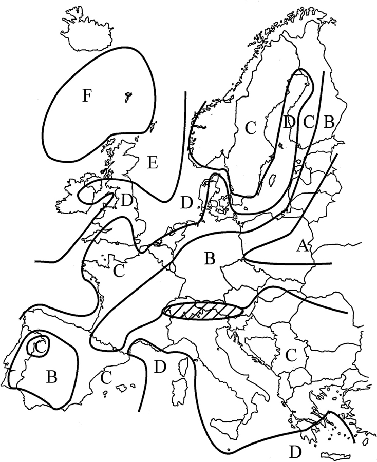
The influence of friction losses of sheave sets shall be calculated by the efficiency of the sheave as described below.
The efficiency of a rope drive, for calculation of the rope pulling force is determined as:
ηS = (ηR)i ηF
with
ηS efficiency of the rope drive,
ηR efficiency of one individual sheave,
i number of fixed sheaves between the rope drum and the sheave set or load,
n number of rope plies on one sheave block. One sheave block consists of the sum total of all the rope plies and sheaves for one rope winding onto a rope drum,
ηF efficiency of the sheave block.
with
ηR efficiency of one sheave.
The efficiency of a rope pulley is dependent on the ratio of the rope pulley diameter to the rope diameter (D : d), on the rope design and on the rope lubrication, in addition to being dependent on the type of bearing arrangement of the pulley (plain bearings or antifriction bearings).
In so far as more accurate values have been proven by means of trials, the following shall be assumed for calculations:
for plain bearings ηR = 0,96
for antifriction bearings ηR = 0,98 … 0,99 (depending on type of bearing, lubrication and seal friction).
It has to be proven that the unloaded hook/hook block can be lowered under the specified working conditions.
99The information given in Figure 1 is mandatory, the format of presentation is a proposal only.
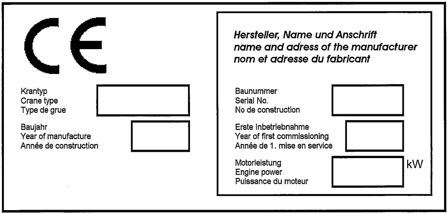
Figure Q. 1 - Example of a Manufacturer’s sign
NOTE CE-mark should be in accordance with EU-Directive 98/37/EC.
100The information given in Table R.1 is mandatory, the format of presentation is a proposal only.
| Wire Rope Certificatea Rope Manufacturer (Name of Company) |
|
|---|---|
| General Information | |
| type of rope date of certificate signature of manufacturer |
|
| Geometric and Material Information | |
| nominal rope diameter [mm] rope length [m] construction of the rope construction of termination kind of lay number of load bearing wires in outer strands surface mass (weight) per unit length [kg/100m] |
|
| Information regarding Limit States | |
| tensile strength of wires [N/mm2] calculated aggregate breaking load [N] minimum breaking load of rope [N] Minimum breaking load of end termination [N] (if provided by rope manufacturer) permissible working conditions: a) Classification of the crane according to ISO 4301-1 b) Service life cycles according to manufacturers' testb, test conditions: Dld = 20, steel sheave Line pull = min. breaking load/4.5 Geometry according to ISO 4308-1 c) Code of practice for examination and discard if not covered by ISO 4309 |
|
| Other Comments | |
| … | |
| a example for certificate - filled in and signed by the rope manufacturer b voluntary information-if available |
|
The information given in Table S.1 is mandatory, the format of presentation is a proposal only.
| Chain Certificatea Chain Manufacturer (Name of company) |
|---|
| General Information |
| type of chain number of certificate date of certificate identification of inspector (name, function) signature of manufacturer |
| design of chain according to standard thread of chain combination of chain batch number quantity of chains shipped quantity by reference manufacturer quantity of links by chain |
| Information regarding Limit States |
| prior test sample: minimum breaking load of chain according to standard: reference Wöhler curve for chain: |
| Other Information |
| specification for assembly reference: specification for cleaning/maintenance reference: others: |
| a example for certificate - filled in and signed by the chain manufacturer |
Figure T.1 gives guideline for the selection of test loads. Test loads may be applied by increasing loads or by increasing radius/outreach.
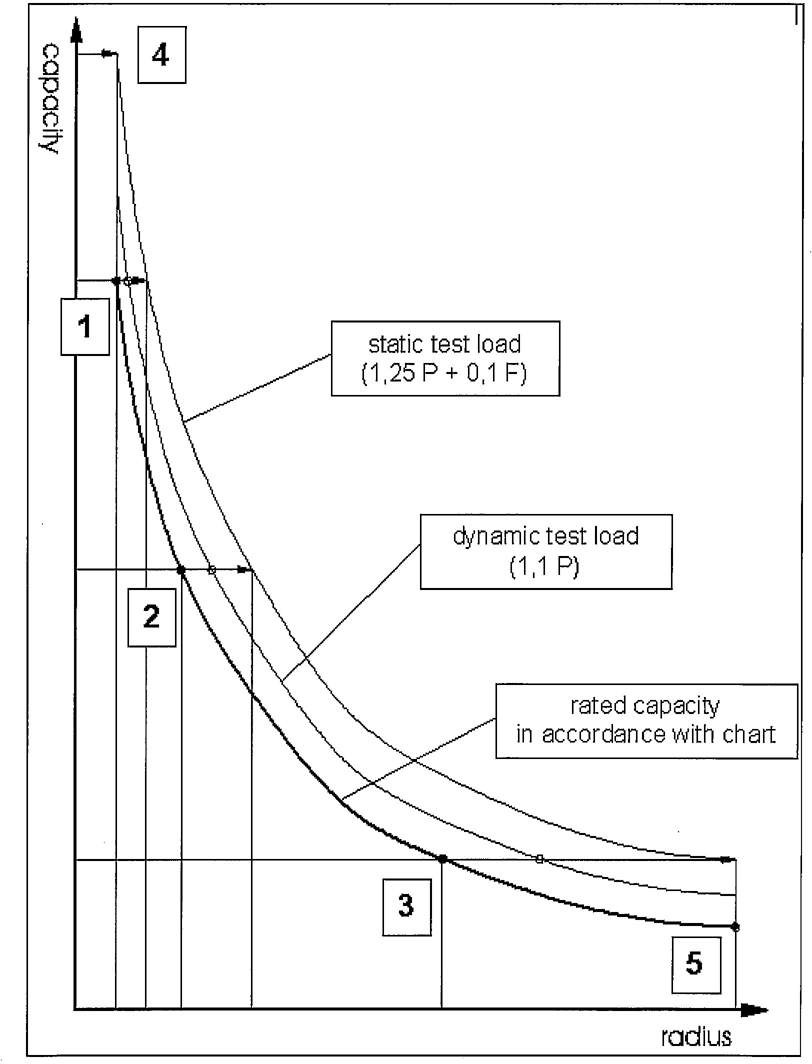
Figure T.1 — Selection of load cases
Static test load (1,25 P + 0,1 F) see ISO 4305:1991 Table 1 and ISO 4310:1981.
Dynamic test load (1,1 P) see ISO 4305:1991 Table 2 and ISO 4310:1981.
103The information given is in Table U.1 is mandatory, the format of presentation is a proposal only.
| Certificate of individual verification | ||
|---|---|---|
| Crane type: | Serial No.: | |
| The visual inspections, functional checks and load tests to validate the conformity of the above mentioned crane with the essential health and safety requirements of the Machine Directive, the corresponding documentation and the duty charts have been carried out according to clause 5 of EN 13000:2004. | ||
| All capacity charts listed in the documentation of the crane are valid, the load limiting and indicating device has been tested and adjusted for correct operation according to the rated capacities given. The load tests were carried out with maximum test loads according to ISO 4310. In case of increased tolerances of the load limiting and indicating device the tolerance shall be given hereby and the test load or additional factors to be applied to the test load shall be listed hereby. | ||
| The load tests have been carried out on samples of configurations. The procedure of the manufacturer for the selection of these samples ensures that all relevant components of the crane have been subjected to maximum loads under the conditions which may occur when the crane is used as intended. | ||
| The Table below shows the tested configurations to provide information for periodic inspection. The load combinations shall be as follows if no specific knowledge allows selection of special load cases. | ||
| test loads at or near to the minimum, medium and maximum radius where the static and dynamic test load can be applied by increasing radius or load, | ||
| a static test load for the minimum radius. | ||
| After the tests the crane was thoroughly examined. The visual inspection, the functional checks and the load tests and the examination itself was supervised by an expert of the manufacturer. | ||
| There have been no findings restricting the safe use of the crane. Other findings are listed in this certificate. | ||
| Date of test: | Date, place, signature: | Location of test: |
| Tested configurations | ||
| Configuration | Chart specification | Remarks/Findings |
| Is there a product standard in the following list that suits the application? | |
| EN 13000 | Cranes — Mobile cranes |
| prEN 14439 | Cranes — Tower cranes |
| Wl 00147 031 | Cranes — Slewing jib cranes |
| Wl 00147 032 | Cranes — Bridge and gantry cranes |
| EN 13852-1 | Cranes — Offshore cranes — Part 1: General purpose offshore cranes |
| prEN 13852-2 | Cranes — Offshore cranes — Part 2: Floating cranes |
| prEN 14492-1: | Cranes — Power driven winches and hoists — Part 1: Power driven winches |
| prEN 14492-2 | Cranes — Power driven winches and hoists — Part 2: Power driven hoists |
| EN 12999 | Cranes — Loader cranes |
| EN 13157 | Cranes — Safety — Hand powered cranes |
| EN 13155 | Cranes — Non-fixed load lifting attachments |
| prEN 14238 | Cranes — Manually controlled load manipulating devices |
| YES | NO |
| Use it directly, plus the standards that are referred to | |
| Use the following: | |
| Wl 00147 005 | Cranes — Terminology |
| prEN 13001-1 | Cranes — General design — Part 1: General principles and requirements |
| prEN 13001-2 | Cranes — General design — Part 2: Load actions |
| prCEN/TS 13001-3-1 | Cranes — General design — Part 3-1: Limit states and proof of competence of steel structures |
| prCEN/TS 13001-3-2 | Cranes — General design — Part 3-2: Limit states and proof of competence of wire ropes |
| prCEN/TS 13001-3-3 | Cranes — General design — Part 3-3: Limit states and proof of competence of wheel/rail contacts |
| prCEN/TS 13001-3-4 | Cranes — General design — Part 3-4: Limit states and proof of competence of machinery |
| EN 13135-1: | Cranes — Equipment — Part 1: Electrotechnical equipment |
| prEN 13135-2 | Cranes — Equipment — Part 2: Non-electrotechnical equipment |
| prEN 13557 | Cranes — Controls and control stations |
| EN 12077-2: | Cranes safety — Requirements for health and safety — Part 2: Limiting and indicating devices |
| Wl 00147 018 | Cranes — Guarding |
| EN 13586 | Cranes — Access |
| prEN 14502-1 | Cranes — Equipment for the lifting of persons — Part 1: Suspended baskets |
| prEN 14502-2 | Cranes — Equipment for the lifting of persons — Part 2: Elevating control stations |
| prEN 14502-3 | Cranes — Equipment for the lifting of persons — Part 3: Spreader beams |
| EN 126441 | Cranes — Information for use and testing — Part 1: Instructions |
| EN 12644-2 | Cranes — Information for use and testing — Part 2: Marking |
| prEN 12644-3 | Cranes — Information for use and testing — Part 3: Fitness for purpose |
This European Standard has been prepared under a mandate given to CEN by the European Commission and the European Free Trade Association to provide one means of conforming to Essential Requirements of the New Approach Directive Machinery 98/37/EC amended by 98/79/EC.
Once this standard is cited in the Official Journal of the European Communities under that Directive and has been implemented as a national standard in at least one Member State, compliance with the normative clauses of this standard except clause 4.2.6.3.2 confers, within the limits of the scope of this standard, a presumption of conformity with the relevant Essential Requirements of that Directive and associated EFTA regulations.
WARNING: Other requirements and other EU Directives may be applicable to the product(s) falling within the scope of this standard.
106BSI —British Standards Institution
BSI is the independent national body responsible for preparing British Standards. It presents the UK view on standards in Europe and at the international level. It is incorporated by Royal Charter.
Revisions
British Standards are updated by amendment or revision. Users of British Standards should make sure that they possess the latest amendments or editions.
It is the constant aim of BSI to improve the quality of our products and services. We would be grateful if anyone finding an inaccuracy or ambiguity while using this British Standard would inform the Secretary of the technical committee responsible, the identity of which can be found on the inside front cover. Tel:+44 (0)20 8996 9000. Fax: +44 (0)20 8996 7400.
BSI offers members an individual updating service called PLUS which ensures that subscribers automatically receive the latest editions of standards.
Buying standards
Orders for all BSI. international and foreign standards publications should be addressed to Customer Services. Tel:+44 (0)20 8996 9001. Fax:+44 (0)20 8996 7001. Email: orders@bsi-global.com. Standards are also available from the BSI website at http://www.bsi-global.com.
In response to orders for international standards, it is BSI policy to supply the BSI implementation of those that have been published as British Standards, unless otherwise requested.
Information on standards
BSI provides a wide range of information on national, European and international standards through its Library and its Technical Help to Exporters Service. Various BSI electronic information services are also available which give details on all its products and services. Contact the Information Centre. Tel:+44 (0)20 8996 7111. Fax:+44 (0)20 8996 7048. Email:info@bsi-global.com.
Subscribing members of BSI are kept up to date with standards developments and receive substantial discounts on the purchase price of standards. For details of these and other benefits contact. Membership Administrator. Tel: +44 (0)20 8996 7002. Fax: +44 (0)20 8996 7001. Email: membership@bsi-global.com.
Information regarding online access to British Standards via British Standards Online can be found at http://www.bsi-global.com//bsonline.
Further information about BSI is available on the BSI website at http://www.bsi-global.com.
Copyright
Copyright subsists in all BSI publications. BSI also holds the copyright, in the UK. of the publications of the international standardization bodies. Except as permitted under the Copyright, Designs and Patents Act 1988 no extract may be reproduced, stored in a retrieval system or transmitted in any form or by any means —electronic, photocopying, recording or otherwise—without prior written permission from BSI.
This does not preclude the free use, in the course of implementing the standard, of necessary details such as symbols, and size, type or grade designations. If these details are to be used for any other purpose than implementation then the prior written permission of BSI must be obtained.
Details and advice can be obtained from the Copyright & Licensing Manager.
Tel: +44 (0)20 8996 7070. Fax: +44 (0)20 8996 7553.
Email: copyright@bsi-global.com.
BSI
389 Chiswick High Road
London
W4 4AL