
In order to promote public education and public safety, equal justice for all, a better informed citizenry, the rule of law, world trade and world peace, this legal document is hereby made available on a noncommercial basis, as it is the right of all humans to know and speak the laws that govern them.
ASSE Standard #1037
Revised: March, 1990
Neither this Standard, nor any portion thereof, may be reproduced without the written consent of the American Society of Sanitary Engineering.
Although this Standard may be used as a benchmark for in-house evaluation, no product may be said to be A.S.S.E. approved unless the manufacturer has applied to the A.S.S.E., has had his product tested by an official A.S.S.E. recognized independent laboratory, according to the applicable A.S.S.E. Standard, and when the product has passed the test, displays the A.S.S.E. Seal on the product. Instructions for receiving the authorization to display the Seal are available from the A.S.S.E. Central Office.
It is recommended that all devices designed for plumbing systems, especially those which pertain to public health and safety, should be installed consistent with local codes by qualified and trained professionals.
American Society of Sanitary Engineering
Bay Village, Ohio
Copyright © 1990, 1986
All rights reserved.
Until the adoption of A.S.S.E. Standard 1037 in 1986, the only specification applicable to flushometer devices and similar products providing a forceful action for flushing water closets and urinals was Federal Specification MIL 29193. With the effort to phase out Federal Specifications, an A.S.S.E. Standard Sub-Committee was formed in the early 1980’s to prepare a draft specification for pressurized fixture flushing devices. This Standard (A.S.S.E. 1037) identifies the necessary performance requirements for such devices, so a proper flushing action in water closets and urinals is achieved with their use.
In June 1989, a Working Group was formed to consider the incorporation of an air-gap separation test for the device as a measure of backflow protection. The A.S.S.E. Product Standards Committee reviewed the proposed changes during its annual meeting in Las Vegas, Nevada, during October 1989, and the draft was then submitted to the A.S.S.E. Board of Directors. The Board voted to approved the revised draft in February, 1990.
Although many of the material specifications are detailed within Section 1.3 of this Standard, it is the responsibility of the manufacture to comply with the requirements of the Safe Drinking Water Act, United States Public Law 93-523.
iiiStuart F. Asay, P.E., Ph.D.
A.S.S.E. Standards Coordinator
Northglenn, Colorado
Robert C. Smith, P.E.
Standards Committee Chairman
U.S. Testing Company, Tulsa, Oklahoma
George Bliss
United Association, Washington, D.C.
Robert DuPont, C.I.P.E.
State of Wisconsin DILHR, Madison, Wisconsin
Richard Emmerson
Chicago Faucet Company, Des Plaines, Illinois
John Gallagher
City of Chicago, Chicago. Illinois
Larry Galowin, Ph.D.
National Institute of Standards and Technology, Gaithersburg, Maryland
Patrick J. Higgins
P.J. Higgins & Associates, Frederick, Maryland
Valentine Lehr, P.E.
Lehr Associates, New York, New York
Herb Panzer, P.E., F.A.S.S.E.
Warren & Panzer Engineers, P.C., New York, New York
Clifford Storm
Broward County Building Inspector, Fort Lauderdale, Florida
Morris Weinberg, P.E., F.A.S.S.E.
Atlantic City, New Jersey
Stuart F. Asay, P.E., Ph.D.
A.S.S.E. Standards Coordinator, Northglenn, Colorado
Rand H. Ackroyd
Watts Regulator Company
Ted Beyke
Honeywell-Braukmann
Sidney Cavanaugh
Water Control International
Bernard D. Clarke
Backflow Preventer Tester
William Dunmire
CMB Industries - FEBCO
Les Englemann
Ames Company
Leo Fleury
Hersey/Grinnell Products
Patrick J. Higgins
P.J. Higgins & Associates
Axel Nelson
Sloan Valve Co.
R. Bruce Martin (alternate)
Water Control International
John Mayfield
Microphor
Richard Myers
Ford Meter Box Company
Burton Preston
Mansfield Plumbing Products
Shabbir Rawalpindiwala
I.A.P.M.O.
Sally Remedios
Canadian Standards Association
James Sargent
Kohler Company
| Section I | 1 | ||
| 1.0 | General | 1 | |
| 1.1 | Scope, Purpose, Construction, Instruction | 1 | |
| 1.2 | Design | 1 | |
| 1.3 | Materials | 2 | |
| 1.4 | Instructions for Marking and Installation | 3 | |
| 1.5 | Accessories | 3 | |
| 1.6 | Classifications | 3 | |
| 1.7 | Recommendations | 3 | |
| Section II | 4 | ||
| 2.0 | Performance Tests and Requirements | 4 | |
| 2.1 | Samples for Test | 4 | |
| 2.2 | Working Pressure and Structural Strength Requirements | 4 | |
| 2.3 | Hydrostatic Test | 4 | |
| 2.4 | Backflow Protection | 4 | |
| Figure 1 | 6 | ||
| Figure 2 | 6 | ||
| Figure 3 | 6 | ||
| Figure 4 | 6 | ||
| 2.5 | Packing and Seals | 7 | |
| 2.6 | Replacement Parts | 7 | |
| 2.7 | Seating Members in Control Stops | 7 | |
| 2.8 | Life Cycle and Flushing Discharge Performance Test | 7 | |
| 2.9 | Life Cycle Test | 8 | |
| 2.10 | Flushing Discharge | 8 | |
| Section III | 8 | ||
| 3.0 | Definitions | 8 | |
| Appendix A | 10 | ||
| A1.0 Scope | 10 | ||
| A2.0 Scope | 10 | ||
| A3.0 Scope | 11 | ||
| A4.0 Scope | 12 | ||
| A5.0 Scope | 13 | ||
| A6.0 Scope | 13 | ||
Pressurized Flushing Devices (Flushometers) for Plumbing Fixtures
This standard establishes basic performance requirements for pressurized flushing devices, for the safe and sanitary operation of plumbing fixtures. Its purpose is also to serve as a guide for producers, distributors, architects, engineers, contractors, home builders, manufacturers, and installers; to form a basis for fair competition, and to provide a basis for identifying devices that conform to this standard.
1.1.2.1 This standard establishes physical requirements, basic performance requirements, and test procedures for pressurized flushing devices for the safe, sanitary operation of plumbing fixtures.
1.1.2.2 While this standard covers the performance requirements for pressurized flushing devices and describes these performance requirements in terms of methods of test applicable to all such units, a number of different materials, designs and methods of operation may be used to meet these requirements.
The following reference standards, which are cited in this Standard, are applicable to pressurized flushing devices and the latest editions shall be used:
ANSI A112.19.2M - Vitreous China Plumbing Fixtures
ANSI A112.19.5 - Trim for Water Closet Bowls, Tanks, and Urinals
ANSI B1.1 -1982 Unified Inch Screw Threads (UN and UNR Thread Form)
ANSI B1.20.1 - Pipe Threads (except dryseal)
ANSI B16.10 - Copper Alloy Solder Joints
ANSI B16.18 - Cast Bronze Solder - Joint Pressure Fittings
ANSI B16.22 - Wrought Copper and Bronze Solder Joint Pressure Fittings
ANSI Z124.4 - Plastic Water Closet Bowls and Tanks
ASTM2 B604 - Decorative Electroplated Coating of Copper/Nickel/Chromium on Plastics
ASTM B456 - Electrodeposited Coatings of Nickel/Chromium
NSF Standard 143
UL4 #73 - Motor Operated Appliances
Required pipe sizes and inlet connections shall be specified by the pressurized flushing device (flushometer) manufacturer.
1Outlet connections shall provide pressure-tight connections to the fixture to which it is assembled, as referenced in American National Standards, specified in ANSI A112.19.2M Vitreous China Plumbing Fixtures.
Tapered pipe threads shall conform to American National Standard ANSI B1.20.1 Pipe Threads (except Dryseal). Straight threads shall conform to American National Standard B1.1 -1982 Unified Inch (UN - UNR) Thread Form, Standard ANSI B16.10 Copper Alloy Solder Joints and B16.22 Wrought Copper and Bronze Solder-Joint Pressure Fittings.
Pressurized flushing devices shall be designed and built such that, after installation, servicing and the replacement of parts may be accomplished using standard tools. Construction shall permit field service without damage or marring the significant surface on the device.
1.2.5.1 Workmanship
Materials used in pressurized flushing devices shall be free of defects, which affect serviceability of operation. The components shall withstand normal handling and installation without damage or permanent distortion of any part.
Materials used shall be free from defects, which would adversely affect the performance of maintenance of individual components or of the overall assembly. Materials not specified herein shall be at least of the same quality used for the intended purpose in commercial practice.
Pressurized flushing device accessories shall be made from materials suitable for the intended purpose, provided such services conform to the performance requirements cited in this standard.
All plastic materials in contact with the potable water shall be evaluated by a recognized testing agency as complying with the applicable sections of NSF Standard #14. Metals presently approved for use in water distribution systems may be used.
1.3.4.1 Metallic Base
If plated, valves and fittings of metallic base materials shall need the performance requirements of Visual Defects, Adhesion, Ductility and Corrosion Testing of the Product Requirements of ASTM B456. Standard Specification for Electrodeposited Coatings of Copper plus Nickel and Chromium.
1.3.4.2 If plated, valves and fittings of plastic base materials shall meet the performance requirements of Appearance, Ductility, Corrosion Testing, Thermal Cycle Testing and Adhesion of the Product Requirements of ASTM B604, Standard Specification for Decorative Electroplated Coatings of Copper, Nickel, Chromium on Plastic.
2The product shall be marked with the manufacturer’s name and model number.
The package shall be marked with the manufacturer’s name and model number.
Installation instructions shall be provided with each unit. The instructions shall include valve adjustment information, and any special rough-in or finishing installation or repair procedures for accessory devices or replacement parts.
Solenoid operated units shall be approved in accordance with the applicable standards.
Pedal, push button, push disk, and remote control devices may be provided.
Pressurized plumbing fixture flushing devices may be classified as exposed or pedal.
Operation methods shall include push button, push disc, remote control, solenoid, and other designs.
All units shall be provided with a backflow prevention device in accordance with applicable standards.
It is recommended that the following paragraph be included with the architect’s and builder’s specifications:
“Pressurized plumbing fixture flushing devices (flushometers) shall be installed in accordance with manufacturer’s recommendations. The supply piping to these devices shall be securely anchored to the building structure to prevent the installed device from unnecessary movement when operated by the user. Care shall be exercised when installing the device to prevent marring the exposed significant surface.”
A control stop is recommended for all pressurized flushing devices installations. Such stops may include an integral check valve. When provided, the control stop shall be tested in accordance with the applicable standards.
3Unless otherwise indicated, three devices (from production runs) for each size and model shall be submitted to the testing agency. One device from each lot shall be selected for testing.
The pressurized flushing device shall be designed to function with cold water at pressures from twenty (20) to one hundred twenty-five (125) p.s.i. (138 to 862 kPa) and shall withstand intermittent shock pressures to one hundred eighty (180) p.s.i. (1240 kPa).
Where applicable, shall withstand, either separately or assembled, a pressure of twenty-five (25) plus or minus one (1) p.s.i.g. (172 +/− 7 kPa) for sixty (60) minutes.
Plastic pressurized flushing devices shall be tested to comply with the loading test in Sections 4.3, 4.4.2, 4.5.3, 4.5.4 of ANSI Z124.4 Plastic Water Closet Bowls and Tanks.
All assembled devices subject to supply line pressure shall withstand a hydrostatic test of five hundred (500) plus or minus twenty (20) p.s.i.g. (3450 +/− 140 kPa).
Hydrostatic pressure shall be applied for a period not less than five (5) minutes.
Units shall show no sign of leakage or permanent distortion.
In the case of products that incorporate an acceptable pressure relief system, tests will be conducted at two (2) times the maximum working pressure of the relief. Discharge into the fixture shall be contained within the product design.
Flushometer tanks shall be provided with backflow protection, which complies with the following tests:
All flushometer tank systems shall pass both the air gap (vacuum) test (See Section 2.4.1 of this Standard) and the plunger test (See Section 2.4.2 Plunger Test of this Standard), or meet the requirements of Section 2.4.3 Backflow Test of this Standard.
42.4.1.1 Procedure
Assemble the flushometer tank to the bowl. Fill the bowl to the flood level rim with water and a dark contrasting dye. A small tube shall be inserted into the up leg of the fixture (bowl) to vent the trapped air and to maximize filling. Remove this tube after filling the trap. With the water supply turned off and the flushometer tank empty, hold the flushometer valve fully open by a mechanical means and apply a constant vacuum of at least twenty-five (25) inches (63.5 cm) of Mercury for a time period of thirty (30) seconds, directly to the shank after fully blocking open all backchecks/backflow devices, and plugging any air ports upstream of the vessel. Then apply intermittent vacuums of two (2), five (5), ten (10), fifteen (15) and twenty-five (25) inches (5.08, 12.7, 25.4,38.1, and 63.5 cm) of Mercury for a time period of thirty (30) minutes. Each application shall be for five (5) seconds on and five (5) seconds off.
2.4.1.2 Criteria
No dye from the bowl shall appear in the flushometer tank.
2.4.2.1 Procedure
Plug the outlet of a closet bowl and empty the flushometer tank. Assemble the flushometer tank to the bowl. Fill the bowl to the flood level rim with water and dark, contrasting dye. A small tube shall be inserted into the up leg of the fixture to vent the trapped air and to maximize filling. Remove this tube after filling the trap. Using a closet plunger, pump the fixture outlet one hundred (100) times. Upon completion of this plunging, remove the flushometer tank and inspect for signs of dye entry into the tank.
2.4.2.2 Criteria
No dye shall enter the flushometer tank during the test.
2.4.3.1 Back Siphonage
2.4.3.1.1 Purpose
There shall be no back siphonage of water from the flushometer tank into the supply line, should all check valve seats become scored or fouled with debris and a vacuum is created in the inlet of the device and the downstream pressure is zero (0) gauge or atmospheric.
2.4.3.1.2 Procedure
All checking members shall be fouled with an appropriate thirty-two thousandths (0.032) inch (8.81 mm) diameter fouling wire, in the location shown for the type of valve construction. (See Figures 2, 3, and 4 of this Standard.) The device shall be installed as in Figure 1 of this Standard, after adding dye solution of the flushometer tank and pressurizing until to the manufacturers recommended working pressure, to establish the normal water level in the flushometer tank with the flushometer tank at atmospheric pressure. The test equipment shall be capable of developing a vacuum of at least a twenty-five (25) inch (63.5 cm) column of Mercury. The tests shall be conducted in sequence as follows:
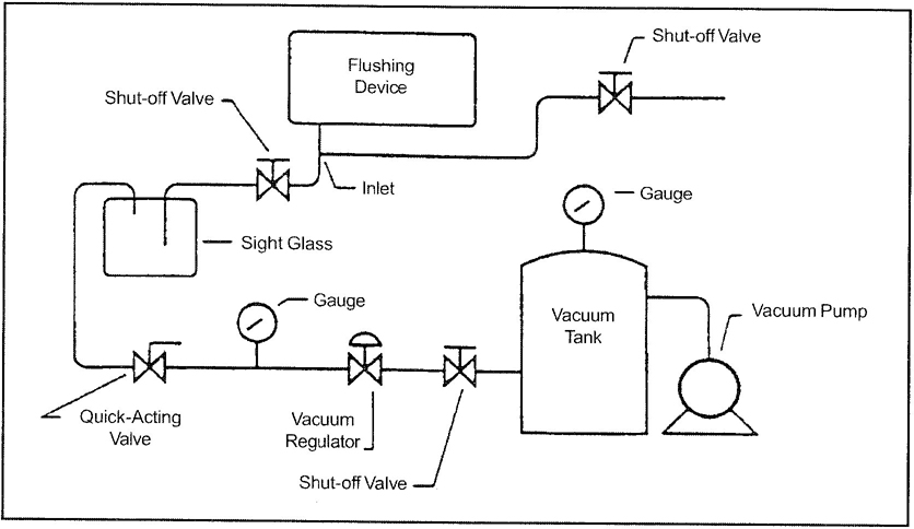
Figure 1
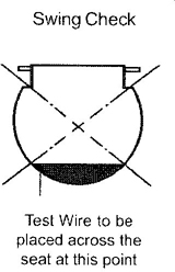
Figure 2
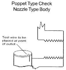
Figure 3
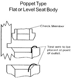
Figure 4
2.4.3.1.3 Criteria
Any colored water in the sight glass shall be cause for rejection of the device.
2.4.3.2 Back Pressure
2.4.3.2.1 Purpose
There shall be no backflow of water from the flushometer tank into the supply, should one check valve seat become scored or fouled with debris and a vacuum is created in the inlet of the device and there is a positive pressure in the flushometer tank.
2.4.3.2.2 Procedure
2.4.3.2.3 Criteria
Any indication of flow of colored water from the inlet of the flushometer tank, which shows in the sight glass, shall be cause for the rejection of the device.
*Note: It shall not be deemed a failure when the design of a flushometer system does not allow for completion of the test.
Packing and seals shall be of such design and quality as to ensure leakproof joints and be capable of provided satisfactory field service.
Joints requiring disassembly to replace worn parts after the fitting is installed shall be designed so that they may be disassembled and reassembled without damaging or marring the significant surface of the fitting using standard tools.
Where seat discs are employed and side expansion of the disc is to be restrained, then the walls of the restraining housing shall show no sign or failure after the life test 2.8.1.
The disc arrangement shall be so made that:
When closed, control stops shall not leak at any test pressure up to two hundred fifty (250) p.s.i.g. (1725 kPa) applied for minimum time period of five (5) minutes.
The pressurized flushing device shall be subjected to the life cycle test for one hundred fifty thousand (150,000) cycles. Average discharge flow rate and running pressure shall be recorded for three consecutive flushes at the start of the test and after each twenty-five thousand (25,000) cycles.
72.8.2.1 Three (3) units shall be tested. Each shall be set up on an individual test stand consisting of the pressurized flushing device affixed to a water supply line with fifty (50) plus or minus ten (10) p.s.i.g. (345 +/− 69 kPa). The units selected for this test shall be typical of standard production quality.
2.8.2.2 Means for the regular discharge of the pressurized flushing device shall be made. Each pressurized flushing device shall be flushed continuously until the required total cycles are completed. The interval between discharges shall be sufficient so as to allow the pressurized flushing device to fully recover.
Upon completion of the cycle tests, units shall be subjected to a static test of one hundred twenty five (125) p.s.i.g. (862 kPa). Units shall be capable of continuous operation without sticking, chattering, or leaking. The average volume per flush shall not vary more than fifteen hundredths (0.15) gallons (0.57 L) or ten (10) percent.
Control stops shall be life cycle tested for five hundred (500) cycles.
2.10.1 Manufacturers Testing
Manufacturers of pressurized flushing devices shall test their products with representative fixtures from three (3) different fixture manufacturers in each of the product categories as listed in ANSI A112.19.2M for which the pressurized flushing device product is intended, to determine conformance with flushing performance to that and other applicable standards. Test methods and procedures shall be as stated in ANSI A112.19.2M or other applicable standards.
2.10.2 Test Reporting
Manufacturers shall report in their literature the classification of plumbing fixtures for which their pressurized flushing devices have been tested and found acceptable.
Definitions not found in this Section may be located in the Plumbing Dictionary, Fourth Edition, published by the A.S.S.E.
The following definitions shall apply to this standard:
Air Gap
The air gap in a water supply system is the unobstructed vertical distance through the free atmosphere between the lowest opening of any pipe of faucet supply water to a tank or plumbing fixture and the flood-level rim of the receptacle.
Accessory
A component which can, at the discretion of the user, be readily added, removed, or replaced and which, when removed, will not prevent the device from fulfilling its primary function.
8Backflow Preventer
Any mechanical device, whether used singly or in combination with other controls, designed to automatically prevent an unintentional reverse flow in a potable water distribution system.
Cold Water
For test purposes, water at a temperature of forty (40) to seventy (70)degrees Fahrenheit (4 to 21 degrees Celsius).
Consumption
Measures volume of water used per flushing cycle.
Control Stop
Valve which is used to control the flow of water into the pressurized flushing device.
Discharge Fitting
Any component installed downstream of the shut-off assembly.
Exposed Fitting
A fitting where the body is mounted above or in front of the fixtures.
Fixture
A receptor that receives water or water borne wastes and discharges such wastes into a drainage system.
Flow Rate
Volume in GPM flowing from the pressurized flushing device outlet.
Flushing Cycle
The complete operating sequence of a water closet, urinal or similar fixture in emptying the contents, cleansing the inside surfaces, and refilling the water seal.
Flushometer Valve
A valve attached to a pressurized water supply pipe and so designed that when actuated, it opens the line for direct flow into the fixture at a rate and quantity to properly operate the fixture and then gradually closes in order to avoid water hammer.
The pipe to which this device is connected is, in itself, of sufficient size that when open, will allow the device to deliver water at a sufficient rate of flow for flushing purposes.
Flushometer Tank
A valve whose function is defined in flushometer valve above but integrated within an accumulator vessel affixed and adjacent to the fixture inlet so as to cause an effective enlargement of the supply line immediately before the flushometer valve.
Gravity Type Flushing System
Products which predominantly rely on storage vessels, open to atmospheric pressure, for flushing plumbing fixtures.
Inlet
Supply opening to the pressurized plumbing fixture flushing device.
Outlet
Discharge opening from the flushometer.
9Pressurized Plumbing Fixture Flushing Devices
A product which uses the water supply to create a pressurized discharge to flush the fixture exclusive of gravity type flushing systems. Flushometer valves and flushometer tanks are examples of pressurized plumbing fixture flushing devices. This term may be substituted for a pressurized flushing device (flushometer) in this standard.
Rough-In
Dimension from finished wall or floor to center of waste or supply opening, or mounting holes.
Running Pressure
The residual pressure in the water supply pipe at the pressurized flushing device or water outlet while the water outlet is open and flowing.
Shall
When used, indicates a mandatory requirement.
Should
When used, indicates a recommended procedure, technique or requirement.
Significant Surface
Any exposed surface which, if marred, would spoil the appearance of the fitting.
Spud
A fitting which is used to connect a pressurized flushing device to a water closet or urinal.
Standard Tools
Tools, such as a screw driver, key wrench, flat jawed wrench, or pliers, which are normally carried by plumbers for the installation and maintenance of plumbing.
Static Pressure
The force per unit of area that is exerted by a fluid upon a surface at rest relative to the fluid.
Trim
Parts, regularly supplied with fixture, as for example, closet spuds, wall hangers, and tank trim. Trim does not include fittings. Reference ANSI A112.19.5 Trim for Water Closet Bowls, Tanks, and Urinals.
This appendix covers requirements of the civil and military agencies of the Federal Government for the procurement of Flushometer Assembly.
The following documents, of the issues in effect on date of invitation for bids or request for proposal, form a part of this appendix to the extent specified herein.
Military Specification
MIL-P-12808 - Plumbing Fixtures and Accessories, Packaging of.
10Military Standard
MIL-STD-105 - Sampling Procedures and Tables for Inspection by Attributes.
(Copies of Government documents required by contractor in connection with specific acquisition functions should be obtained from the contracting activity or from the Commanding Officer, Naval Publication and Forms Center, 5801 Tabor Avenue, Philadelphia, PA 19120).
Definitive Part Number(DPN)
The Flushometer assembly covered by this standard shall be identified by a DPN. This part number is intended for cataloging and ordering purposes (see 16) and not for surface marking on the product. The DPN shall be written as shown:
DPN ______________ 1037 - XXXXXX
ASSE document number_________
Part numbers_________
A3.1.1 Part numbers
A3.2 Standard Commercial Product.
The Flushometer assembly shall, as a minimum, be in accordance with the requirements of this standard. Additional or better features which are not specifically prohibited by this standard but which are a part of the manufacturer’s standard commercial product, shall be included in the Flushometer being furnished. A standard commercial product is a product which has been sold or is being currently offered for sale on the commercial market through advertisements or manufacturer’s catalogs, or brochures, and represents the latest production model.
A3.3 Finish
All exposed parts, trim and hardware shall be polished chrome plated; stainless steels shall be polished commercial finish.
A4.1 Responsibility for Inspection
The contractor shall be responsible for the performance of all inspection requirements as specified herein. The contractor may use his own or any other facilities suitable for the performance of the inspection requirements unless disapproved by the Government. The Government reserves the right to perform any of the inspections set forth in the standard where such inspections are deemed necessary to assure supplies and services conform to prescribed requirements.
A4.2 Quality Conformance Inspection
Except as specified herein, the quality conformance inspection shall be performed on each sample selected (see A4.3) to determine compliance with this standard and shall include the following:
A4.3 Sampling
Sampling and inspection procedures shall be in accordance with MIL-STD-105. The unit of product shall be one complete flushing device. All flushing devices of the same description offered for delivery at one time shall be considered a lot for the purpose of inspection. If an inspection lot is rejected, the contractor may reword it to correct the defects, or screen out the defective units, and resubmit for a complete inspection. Resubmitted lots shall be reinspected using tightened inspection. If the rejected lot was screened, reinspection shall be limited to the defect causing rejection. If the lot was reprocessed, reinspection shall be performed for all defects. Rejected lots shall be separate from new lots, and shall be clearly identified as reinspected lots.
The packaging, packing, and marking shall be in accordance with MIL-P-12808, with the level of preservation and packing as specified (see A6.0).
Acquisition documents should specify the following: