
In order to promote public education and public safety, equal justice for all, a better informed citizenry, the rule of law, world trade and world peace, this legal document is hereby made available on a noncommercial basis, as it is the right of all humans to know and speak the laws that govern them.
ASME B30.5-2004
(Revision of ASME B30.5-2000)
Mobile and Locomotive Cranes
Safety Standard for Cableways, Cranes, Derricks, Hoists, Hooks, Jacks, and Slings
AN AMERICAN NATIONAL STANDARD


ASME B30.5-2004
(Revision of ASME B30.5-2000)
SAFETY STANDARD FOR CABLEWAYS, CRANES, DERRICKS, HOISTS, HOOKS, JACKS, AND SLINGS
iDate of Issuance: September 27, 2004
The next edition of this Standard is scheduled for publication in 2007. There will be no addenda issued to this edition.
ASME issues written replies to inquiries concerning interpretations of technical aspects of this Standard. Interpretations are published on the ASME Web site under the Committee Pages at http://www.asme.org/codes/as they are issued, and will also be published within the next edition of the Standard.
ASME is the registered trademark of The American Society of Mechanical Engineers.
This code or standard was developed under procedures accredited as meeting the criteria for American National Standards. The Standards Committee that approved the code or standard was balanced to assure that individuals from competent and concerned interests have had an opportunity to participate. The proposed code or standard was made available for public review and comment that provides an opportunity for additional public input from industry, academia, regulatory agencies, and the public-at-large.
ASME does not “approve,” “rate,” or “endorse” any item, construction, proprietary device, or activity.
ASME does not take any position with respect to the validity of any patent rights asserted in connection with any items mentioned in this document, and does not undertake to insure anyone utilizing a standard against liability for infringement of any applicable letters patent, nor assume any such liability. Users of a code or standard are expressly advised that determination of the validity of any such patent rights, and the risk of Infringement of such rights, is entirely their own responsibility.
Participation by federal agency representative(s) or person(s) affiliated with industry is not to be interpreted as government or industry endorsement of this code or standard.
ASME accepts responsibility for only those interpretations of this document issued in accordance with the established ASME procedures and policies, which precludes the issuance of interpretations by individuals.
No part of this document may be reproduced in any form,
in an electronic retrieval system or otherwise,
without the prior written permission of the publisher.
The American Society of Mechanical Engineers
Three Park Avenue, New York, NY 10016-5990
Copyright © 2004 by
THE AMERICAN SOCIETY OF MECHANICAL ENGINEERS
All rights reserved
Printed in U.S.A.
| Foreword | v | |
| Committee Roster | vi | |
| B30 Series Introduction | viii | |
| Summary of Changes | xi | |
| Chapter 5-0 | Scope, Definitions, and References | 1 |
| Section 5-0.1 | Scope of B30.5 | 1 |
| Section 5-0.2 | Definitions | 1 |
| Section 5-0.3 | References | 7 |
| Chapter 5-1 | Construction and Characteristics | 8 |
| Section 5-1.1 | Load Ratings | 8 |
| Section 5-1.2 | Stability (Backward and Forward) | 9 |
| Section 5-1.3 | Boom Hoist, Load Hoist, and Telescoping Boom Mechanisms | 14 |
| Section 5-1.4 | Swing Mechanism | 15 |
| Section 5-1.5 | Crane Travel | 15 |
| Section 5-1.6 | Controls | 15 |
| Section 5-1.7 | Ropes and Reeving Accessories | 18 |
| Section 5-1.8 | Cabs | 19 |
| Section 5-1.9 | General Requirements | 20 |
| Section 5-1.10 | Structural Performance | 21 |
| Section 5-1.11 | Cranes Used for Other Than Lifting Service | 22 |
| Chapter 5-2 | Inspection, Testing, and Maintenance | 23 |
| Section 5-2.1 | Inspection — General | 23 |
| Section 5-2.2 | Testing | 24 |
| Section 5-2.3 | Maintenance | 25 |
| Section 5-2.4 | Rope Inspection, Replacement, and Maintenance | 25 |
| Chapter 5-3 | Operation | 28 |
| Section 5-3.1 | Qualifications for and Conduct of Operations and Operating Practices | 28 |
| Section 5-3.2 | Operating Practices | 30 |
| Section 5-3.3 | Signals | 33 |
| Section 5-3.4 | Miscellaneous | 33 |
| Figures | ||
| 1 | Commercial Truck-Mounted Crane — Telescoping Boom | 1 |
| 2 | Commercial Truck-Mounted Crane — Nontelescoping Boom | 2 |
| 3 | Crawler Crane | 2 |
| 4 | Crawler Crane — Telescoping Boom | 2 |
| 5 | Locomotive Crane | 3 |
| 6 | Wheel-Mounted Crane (Multiple Control Stations) | 3 |
| 7 | Wheel-Mounted Crane — Telescoping Boom (Multiple Control Stations) | 4 |
| 8 | Wheel-Mounted Crane (Single Control Station) | 4 |
| 9 | Wheel-Mounted Crane — Telescoping Boom (Single Control Station, Rotating) | 4 |
| 10 | Wheel-Mounted Crane — Telescoping Boom (Single Control Station, Fixed) | 5 |
| 11 | Work Areas | 10 |
| 12 | Telescopic Boom Crane Control Diagram | 16 |
| 13 | Nontelescopic Boom Crane Control Diagram | 17 iii |
| 14 | Dead Ending Rope in a Socket | 19 |
| 15 | Core Failure in 19 × 7 Rotation-Resistant Rope | 26 |
| 16 | Examples of Typical Unequal Outrigger Extension Positions | 32 |
| 17 | Standard Hand Signals for Controlling Crane Operations | 34 |
| 18 | Danger Zone for Cranes and Lifted Loads Operating Near Electrical Transmission Lines | 37 |
| Tables | ||
| 1 | Crane Load Ratings | 8 |
| 2 | Required Clearance for Normal Voltage in Operation Near High-Voltage Power Lines and Operation in Transit With No Load and Boom or Mast Lowered | 39 |
This American National Standard, Safety Standard for Cableways, Cranes, Derricks, Hoists, Hooks, Jacks, and Slings, has been developed under the procedures accredited by the American National Standards Institute (formerly the United States of America Standards Institute). This Standard had its beginning in December 1916 when an eight-page Code of Safety Standards for Cranes, prepared by an ASME Committee on the Protection of Industrial Workers, was presented to the annual meeting of the ASME.
Meetings and discussions regarding safety on cranes, derricks, and hoists were held from 1920 to 1925, involving the ASME Safety Code Correlating Committee, the Association of Iron and Steel Electrical Engineers, the American Museum of Safety, the American Engineering Standards Committee (later changed to American Standards Association and subsequently to the USA Standards Institute), Department of Labor — State of New Jersey, Department of Labor and Industry — State of Pennsylvania, and the Locomotive Crane Manufacturers Association. On June, 11, 1925, the American Engineering Standards Committee approved the ASME Safety Code Correlating Committee's recommendation and authorized the project with the U.S. Department of the Navy, Bureau of Yards and Docks, and ASME as sponsors.
In March 1926, invitations were issued to 50 organizations to appoint representatives to a Sectional Committee. The call for organization of this Sectional Committee was sent out October 2, 1926, and the committee organized November 4, 1926, with 57 members representing 29 national organizations. The Safety Code for Cranes, Derricks, and Hoists, ASA B30.2-1943, was created from the eight-page document referred to in the first paragraph. This document was reaffirmed in 1952 and widely accepted as a safety standard.
Due to changes in design, advancement in techniques, and general interest of labor and industry in safety, the Sectional Committee, under the joint sponsorship of ASME and the Naval Facilities Engineering Command, U.S. Department of the Navy, was reorganized as an American National Standards Committee on January 31, 1962, with 39 members representing 27 national organizations.
The format of the previous code was changed so that separate volumes (each complete as to construction and installation; inspection, testing, and maintenance; and operation) would cover the different types of equipment included in the scope of B30.
In 1982, the Committee was reorganized as an Accredited Organization Committee, operating under procedures developed by ASME and accredited by the American National Standards Institute.
This Standard presents a coordinated set of rules that may serve as a guide to government and other regulatory bodies and municipal authorities responsible for the guarding and inspection of the equipment falling within its scope. The suggestions leading to accident prevention are given both as mandatory and advisory provisions; compliance with both types may be required by employers of their employees.
In case of practical difficulties, new developments, or unnecessary hardship, the administrative or regulatory authority may grant variances from the literal requirements or permit the use of other devices or methods, but only when it is clearly evident that an equivalent degree of protection is thereby secured. To secure uniform application and interpretation of this Standard, administrative or regulatory authorities are urged to consult the B30 Committee, in accordance with the format described in Section III of the Introduction, before rendering decisions on disputed points.
Safety codes and standards are intended to enhance public safety. Revisions result from committee consideration of factors such as technological advances, new data, and changing environmental and industry needs. Revisions do not imply that previous editions were inadequate.
Suggestions for the improvement of this volume of the Standard are welcome. They should be addressed to The American Society of Mechanical Engineers; Secretary, B30 Main Committee; Three Park Avenue; New York, NY 10016-5990.
This volume of the Standard, which was approved by the B30 Committee and by ASME, was approved by ANSI and designated as an American National Standard on May 25, 2004.
vSafety Standards for Cableways, Cranes, Derricks, Hoists, Hooks, Jacks, and Slings
(The following is the roster of the Committee at the time of approval of this Standard.)
STANDARDS COMMITTEE OFFICERS
P. S. Zorich, Chair
B. D. Closson, Vice Chair
J. D. Wendler, Secretary
STANDARDS COMMITTEE PERSONNEL
N. E. Andrew, Sverdup Technology, Inc.
W. T. Hargrove, Alternate, ManTech International Corp.
R. E. Bluff, Gantry Constructors, Inc.
R. J. Bolen, E. I. du Pont de Nemours & Co., Inc.
G. B. Hetherston, Alternate, E. I. du Pont de Nemours & Co., Inc.
A. D. Brown, A. D. Brown Co.
L. D. DeMark, International Union of Operating Engineers
S. C. Buck, Alternate, International Union of Operating Engineers
T. A. Christensen, Alliance of American Insurers/Liberty Mutual Insurance Co.
M. W. Mills, Alternate, Liberty Mutual Group
B. D. Closson, NACB Technical Services, Inc.
T. L. Blanton, Alternate, NACB Group, Inc.
J. P. Colletti, John P. Colletti & Associates, Inc.
R. A. Dahlin, Walker Magnetics Group, Inc.
J. W. Downs, Jr., Alternate, Downs Crane & Hoist Co., Inc.
D. W. Eckstine, Eckstine & Associates
R. J. Edwards, Schwing America, Inc.
R. H. Fowler, U.S. Department of the Air Force
J. L. Franks, Consultant
R. C. Slater, Alternate, McKay International Engineering
J. L. Gordon, FKI Industries, Inc.
R. R. Reisinger, Alternate, FKI Industries, Inc.
N. C. Hargreaves, Power Crane and Shovel Association/Terex Corp.
E. D. Fidler, Alternate, Terex Corp.
J. J. Headley, Crane Institute of America, Inc.
R. M. Parnell, Alternate, Industrial Training International
C. W. Ireland, National Oilwell
A. Egging, Alternate, National Oilwell
L. S. Johnson, AMECO
R. M. Kohner, Landmark Engineering Services
H. I. Shapiro, Alternate, Howard I. Shapiro & Associates Consulting Engineers
H. G. Leidich, Ingersoll-Rand
J. T. Perkins, Alternate, Ingersoll-Rand
C. E. Lucas, The Crosby Group
P. A. Boeckman, Alternate, The Crosby Group
E. K. Marburg, Columbus McKinnon Corp.
M. G. Miller, Alternate, Columbus McKinnon Corp.
L. D. Means, Wire Rope Technical Board/Means Engineering and Consulting
D. M. Sleightholm, Alternate, Bridon America Corp.
K. J. Miller, Jacobs Engineering Group
D. W. Smith, Alternate, Chicago Bridge and Iron Co.
G. L. Owens, Granite Construction Co.
J. E. Richardson, U.S. Department of the Navy
J. W. Rowland III, Association of Iron and Steel Engineers/Bethlehem Steel Corp.
E. E. Rudy, U.S. Department of the Army
J. C. Ryan, Boh Bros. Construction Co.
A. Ruud, Alternate, Phillips and Jordan
D. Sayenga, Associated Wire Rope Fabricators
D. J. Bishop, Alternate, Bishop Lifting Products, Inc.
G. W. Shields, Caterpillar, Inc.
R. G. Strain, Advanced Automation Technologies, Inc.
A. R. Toth, Morris Material Handling
B. E. Weir, Jr., National Erectors Association/Norris Brothers Co., Inc.
J. Conant, Alternate, Conant Crane Rental Co.
J. D. Wendler, ASME International
R. C. Wild, U.S. Army Corps of Engineers
S. G. Testerman, Alternate, U.S. Army Corps of Engineers
D. N. Wolff, National Crane Corp.
A. L. Calta, Alternate, National Crane Corp.
P. S. Zorich, RZP International Ltd.
HONORARY MEMBERS
viJ. M. Kilbert, Lift-All Co., Inc.
R. W. Parry, Consultant
B30.5 SUBCOMMITTEE PERSONNEL
J. C. Ryan, Chair, Boh Bros. Construction Co.
R. J. Bolen, E. I. du Pont de Nemours & Co., Inc.
L. D. DeMark, International Union of Operating Engineers
S. C. Buck,Alternate, International Union of Operating Engineers
D. E. Dickie, Construction Safety Association of Ontario
D. W. Eckstine, Eckstine & Associates
N. C. Hargreaves, Power Crane and Shovel Association/Terex Corp.
E. D. Fidler, Alternate, Terex Corp.
L. S. Johnson, AMECO
G. L. Owens, Alternate, Granite Construction Co.
R. M. Kohner, Landmark Engineering Services
J. Lanning, Manitowoc Crane Group
D. Ritchie, The Construction Safety Council
W. P. Rollins, Manitowoc Crane Group
T. E. Ward-Robichaux, Alternate, Equipment Solutions LLC
J. W. Rowland III, Association of Iron and Steel Engineers/Bethlehem Steel Corp.
R.C. Wild, U.S. Army Corps of Engineers
D. N. Wolff, National Crane Corp.
A. L. Calta, Alternate, National Crane Corp.
SAFETY STANDARD FOR CABLEWAYS, CRANES, DERRICKS, HOISTS, HOOKS, JACKS, AND SLINGS
This Standard is one of a series of safety standards on various subjects that have been formulated under the general auspices of the American National Standards Institute. One purpose of the Standard is to serve as a guide to governmental authorities having jurisdiction over subjects within the scope of the Standard. It is expected, however, that the Standard will find a major application in industry, serving as a guide to manufacturers, purchasers, and users of the equipment.
For the convenience of the user, the Standard has been divided into separate volumes.
| B30.1 | Jacks |
| B30.2 | Overhead and Gantry Cranes (Top Running Bridge, Single or Multiple Girder, Top Running Trolley Hoist) |
| B30.3 | Construction Tower Cranes |
| B30.4 | Portal, Tower, and Pedestal Cranes |
| B30.5 | Mobile and Locomotive Cranes |
| B30.6 | Derricks |
| B30.7 | Base Mounted Drum Hoists |
| B30.8 | Floating Cranes and Floating Derricks |
| B30.9 | Slings |
| B30.10 | Hooks |
| B30.11 | Monorails and Underhung Cranes |
| B30.12 | Handling Loads Suspended From Rotorcraft |
| B30.13 | Storage/Retrieval (S/R) Machines and Associated Equipment |
| B30.14 | Side Boom Tractors |
| B30.15 | Mobile Hydraulic Cranes Note: B30.15-1973 has been withdrawn. The revision of B30.15 is included in the latest edition of B30.5. |
| B30.16 | Overhead Hoists (Underhung) |
| B30.17 | Overhead and Gantry Cranes (Top Running Bridge, Single Girder, Underhung Hoist) |
| B30.18 | Stacker Cranes (Top or Under Running Bridge, Multiple Girder With Top or Under Running Trolley Hoist) |
| B30.19 | Cableways |
| B30.20 | Below-the-Hook Lifting Devices |
| B30.21 | Manually Lever Operated Hoists |
| B30.22 | Articulating Boom Cranes |
| B30.23 | Personnel Lifting Systems |
| B30.24 | Container Cranes1 |
| B30.25 | Scrap and Material Handlers |
| B30.26 | Rigging Hardware1 |
| B30.27 | Material Placement Systems1 |
| B30.28 | Balance-Lifting Units1 |
| 1 B30.24, B30.26, B30.27, and B30.28 are in the developmental stage. | |
If these standards are adopted for governmental use, the references to other national codes and standards in the specific volumes may be changed to refer to the corresponding regulations of the governmental authorities.
The use of cableways, cranes, derricks, hoists, hooks, jacks, and slings is subject to certain hazards that cannot be met by mechanical means but only by the exercise of intelligence, care, and common sense. It is therefore essential to have personnel involved in the use and operation of equipment who are competent, careful, physically and mentally qualified, and trained in the safe operation of the equipment and the handling of the loads. Serious hazards are overloading, dropping or slipping of the load caused by improper hitching or slinging, obstructing the free passage of the load, and using equipment for a purpose for which it was not intended or designed.
The Standards Committee fully realizes the importance of proper design factors, minimum or maximum sizes, and other limiting dimensions of wire rope or chain and their fastenings, sheaves, sprockets, drums, and similar equipment covered by the Standard, all of which are closely connected with safety. Sizes, strengths, and similar criteria depend on many different factors, often varying with the installation and uses. These factors depend on the condition of the equipment or material; the loads; the acceleration or speed of the ropes, chains, sheaves, sprockets, or drums; the type of attachments; the number, size, and arrangement of sheaves or other parts; environmental conditions causing corrosion or wear; and many variables that must be considered in each individual case. The rules given in the Standard must be interpreted accordingly, and judgment must be used in determining their application.
The Standards Committee will be glad to receive criticisms of this Standard's requirements and suggestions
viiifor its improvement, especially those based on actual experience in application of the rules.
Suggestions for changes to the Standard should be submitted to the Secretary of the B30 Committee, ASME, Three Park Avenue, New York, NY 10016-5990, and should be in accordance with the following format:
(a) Cite the specific paragraph designation of the pertinent volume.
(b) Indicate the suggested change (addition, deletion, revision, etc.).
(c) Briefly state the reason and/or evidence for the suggested change.
(d) Submit suggested changes to more than one paragraph in the order that the paragraphs appear in the volume.
The B30 Committee will consider each suggested change in a timely manner in accordance with its procedures.
This Standard applies to the construction, installation, operation, inspection, and maintenance of jacks; power-operated cranes, monorails, and crane runways; power-operated and manually operated derricks and hoists; lifting devices, hooks, and slings; and cableways.
This Standard does not apply to track and automotive jacks, railway or automobile wrecking cranes, shipboard cranes, shipboard cargo-handling equipment, well-drilling derricks, skip hoists, mine hoists, truck body hoists, car or barge pullers, conveyors, excavating equipment, or equipment falling within the scope of the following Committees: A10, A17, A90, A92, A120, B20, B56, and B77.
This Standard is designed to
(a) guard against and minimize injury to workers, and otherwise provide for the protection of life, limb, and property by prescribing safety requirements
(b) provide direction to owners, employers, supervisors, and others concerned with, or responsible for, its application
(c) guide governments and other regulatory bodies in the development, promulgation, and enforcement of appropriate safety directives
Upon request, the B30 Committee will render an interpretation of any requirement of the Standard. Interpretations can only be rendered in response to a written request sent to the Secretary of the B30 Committee, ASME, Three Park Avenue, New York, NY 10016-5990.
The request for interpretation should be clear and unambiguous. It is further recommended that the inquirer submit his request utilizing the following format.
| Subject: | Cite the applicable paragraph number(s) and provide a concise description. |
| Edition: | Cite the applicable edition of the pertinent volume for which the interpretation is being requested. |
| Question: | Phrase the question as a request for an interpretation of a specific requirement suitable for general understanding and use, not as a request for approval of a proprietary design or situation. The inquirer may also include any plans or drawings that are necessary to explain the question; however, they should not contain any proprietary names or information. |
Requests that are not in this format will be rewritten in this format by the Committee prior to being answered, which could change the intent of the original request.
ASME procedures provide for reconsideration of any interpretation when or of additional information that might affect an interpretation is available. Further, persons aggrieved by an interpretation may appeal to the cognizant ASME Committee or Subcommittee. ASME does not “approve,” “certify,” “rate,” or “endorse” any item, construction, proprietary device, or activity.
(a) Effective Date. The effective date of this volume for the purpose of defining new and existing installations shall be 1 year after its date of issuance.
(b) New Installations. Construction, installation, inspection, testing, maintenance, and operation of equipment manufactured and facilities constructed after the effective date of this volume shall conform to the mandatory requirements of this volume.
(c) Existing Installations. Inspection, testing, maintenance, and operation of equipment manufactured and facilities constructed prior to the effective date of this volume shall be done, as applicable, in accordance with the requirements of this volume.
It is not the intent of this volume to require retrofitting of existing equipment. However, when an item is being modified, its performance requirement shall be reviewed relative to the current volume. If the performance differs substantially, the need to meet the current requirement shall be evaluated by a qualified person selected by the owner (user). Recommended changes shall be made by the owner (user) within 1 year.
ixMandatory rules of this volume are characterized by use of the word shall. If a provision is of an advisory nature, it is indicated by use of the word should and is a recommendation to be considered, the advisability of which depends on the facts in each situation.
This Standard contains SI (metric) units and U.S. Customary units. The values stated in U.S. Customary units are to be regarded as the standard. The SI units are a direct (soft) conversion from the U.S. Customary units.
xFollowing approval by the ASME B30 Committee and ASME, and after public review, ASME B30.5-2004 was approved by the American National Standards Institute on May 25, 2004.
ASME B30.5-2004 includes editorial changes, revisions, and corrections introduced in ASME B30.5a-2002, as well as the following changes identified by a margin note, (04).
| Page | Location | Change |
|---|---|---|
| viii-x | B30 Series Introduction | General and Section VI revised |
| 1 | Section 5-0.1 | Third paragraph revised |
| 2,5,6 | 5-0.2.2 | (1) Definition for luffing attachment added (2) Definition of operational aid revised |
| 7 | Section 5-0.3 | B30.23 reference added |
| 8 | Table 1 | Converted from in-text table and revised |
| 18, 19 | 5-1.7.2 | Revised in its entirety |
| Fig. 14 | Corrected by errata | |
| 20 | 5-1.9.3(d) | Added |
| 21 | 5-1.9.9 | Revised |
| 22 | Section 5-1.11 | Added |
| 24, 25 | 5-2.1.6(c) | Revised |
| 5-2.2.1(a)(7) | Added | |
| 5-2.2.2 | Revised | |
| 5-2.3.1(a) | Revised | |
| 5-2.3.3(b)(2) | Revised | |
| 29 | 5-3.1.3(c) | Revised |
| 30 | 5-3.2.1.1(c) | Revised |
| 5-3.2.1.1(d) | Revised | |
| 5-3.2.1.2(a) | Revised | |
| 5-3.2.1.2(b) | Revised | |
| 31 | 5-3.2.1.5(h) | Revised in its entirety |
| 32 | Fig. 16 | Added |
| 5-3.2.2 | Revised in its entirety | |
| 33 | Section 5-3.3 | Revised in its entirety |
| 34-36 | Fig. 17 | Redesignated from Fig. 16 |
| 37, 38 | Fig. 18 | Redesignated from Fig. 17 xi |
| 39, 40 | Table 2 | Redesignated from Table 1 |
| 5-3.4.5.2(e) | Revised | |
| 5-3.4.5.3(j) | Revised | |
| 5-3.4.5.4(g) | Revised |
SPECIAL NOTE:
The interpretations to ASME B30.5 are included in this edition as a separate section for the user's convenience.
xiiMOBILE AND LOCOMOTIVE CRANES
Within the general scope defined in Section 1, American National Standard B30.5 applies to crawler cranes, locomotive cranes, wheel-mounted cranes, and any variations thereof that retain the same fundamental characteristics. The scope includes only cranes of the above types that are basically powered by internal combustion engines or electric motors. Side boom tractors and cranes designed for railway and automobile wreck clearance, digger derricks, cranes manufactured specifically for, or when used for, energized electrical line service, knuckle boom, trolley boom cranes, and cranes having a maximum rated capacity of one ton or less are excluded.
Special adaptions to the general types of machines covered by this volume, where applicable, fall under this scope.
Some basic machine types within this scope are used alternatively for lifting service and for applications not considered to be lifting service. All of the requirements of this volume are applicable to such machines when used for lifting service. However, at a minimum, Section 5-1.11, Chapter 5-2, and Section 5-3.1 of this volume apply to machines when used in other than lifting service.
commercial truck-mounted crane: a crane consisting of a rotating superstructure (center post or turntable), boom, operating machinery, and one or more operator's stations mounted on a frame attached to a commercial truck chassis, usually retaining a payload hauling capability whose power source usually powers the crane. Its function is to lift, lower, and swing loads at various radii (see Figs. 1 and 2).
crawler crane: a crane consisting of a rotating superstructure with a power plant, operating machinery, and boom, mounted on a base and equipped with crawler treads for travel. Its function is to lift, lower, and swing loads at various radii (see Figs. 3 and 4).
locomotive crane: a crane consisting of a rotating superstructure with a power plant, operating machinery, and boom, mounted on a base or car equipped for travel on a railroad track. It may be self-propelled or propelled by an outside source. Its function is to lift, lower, and swing loads at various radii (see Fig. 5).
wheel-mounted crane (multiple control stations): a crane consisting of a rotating superstructure, operating machinery, and operator's station and boom, mounted on a crane carrier equipped with axles and rubber-tired wheels for travel, a power source(s), and having separate stations for driving and operating. Its function is to lift, lower, and swing loads at various radii (see Figs. 6 and 7).
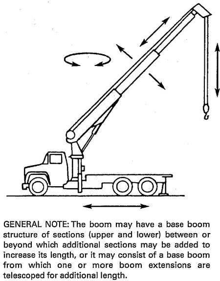
Fig. 1 Commercial Truck–Mounted Crane – Telescoping Boom
1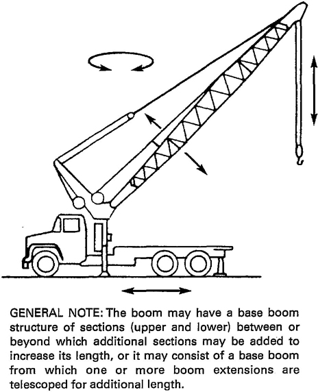
Fig. 2 Commercial Truck-Mounted Crane— Nontelescoping Boom
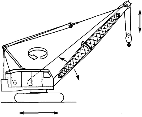
Fig. 3 Crawler Crane
wheel-mounted crane (single control station): a crane consisting of a rotating superstructure, operating machinery, and boom, mounted on a crane carrier equipped with axles and rubber-tired wheels for travel, a power source, and having a single control station for driving and operating. Its function is to lift, lower, and swing loads at various radii (see Figs. 8,9, and 10).
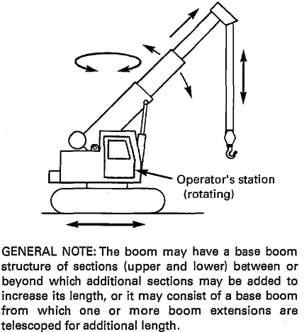
Fig. 4 Crawler Crane — Telescoping Boom
accessory: a secondary part of assembly of parts that contributes to the overall function and usefulness of a machine.
administrative or regulatory authority: a governmental agency or the employer in the absence of governmental jurisdiction.
angle indicator (boom): an accessory that measures the angle of the boom to the horizontal.
anti-two-block device: a device that, when activated, disengages all crane functions whose movement can cause two-blocking.
appointed: assigned specific responsibilities by the employer or the employer's representative.
authorized: appointed by a duly constituted administrative or regulatory authority.
auxiliary hoist: a secondary hoist rope system used either in conjunction with, or independently of, the main hoist system.
axis of rotation: the vertical axis around which the crane superstructure rotates.
axle: the shaft or spindle with which or about which a wheel rotates. On wheel-mounted cranes it refers to a type of axle assembly including housings, gearing, differential, bearings, and mounting appurtenances.
axle (bogie): two or more axles mounted in tandem in a frame so as to divide the load between the axles and permit vertical oscillation of the wheels.
ballast: weight used to supplement the weight of the machine in providing, stability for lifting working loads
2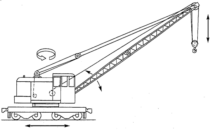
Fig. 5 Locomotive Crane
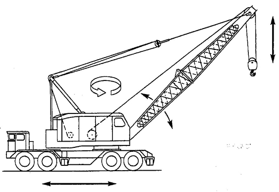
Fig. 6 Wheel-Mounted Crane (Multiple Control Stations)
(the term ballast is normally associated with locomotive cranes).
base (mounting): the traveling base on which the rotating superstructure of a locomotive or crawler crane is mounted.
boom (crane): a member hinged to the rotating superstructure and used for supporting the hoisting tackle.
boom angle: the angle above or below horizontal of the longitudinal axis of the base boom section.
boom hoist mechanism: means for supporting the boom and controlling the boom angle.
boom point: the outer extremity of the crane boom, containing the hoist sheave assembly.
boom point sheave assembly: an assembly of sheaves and pin built as an integral part of the boom point.
boom stop: a device used to limit the angle of the boom at the highest recommended position.
brake: a device used for retarding or stopping motion.
cab: a housing that covers the rotating superstructure machinery or the operator's or driver's station.
clutch: a means for engagement or disengagement of power.
commercial truck vehicle: a commercial motor vehicle designed primarily for the transportation of property in connection with business and industry.
3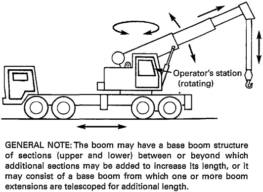
Fig. 7 Wheel-Mounted Crane— Telescoping Boom (Multiple Control Stations)
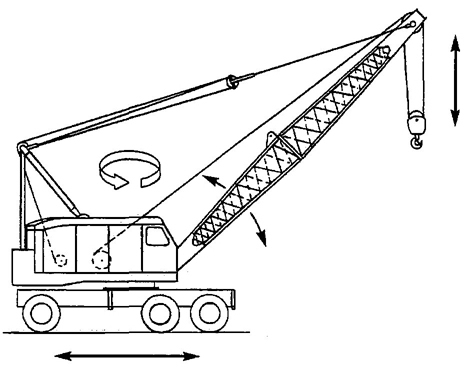
Fig. 8 Wheel-Mounted Crane (Single Control Station)
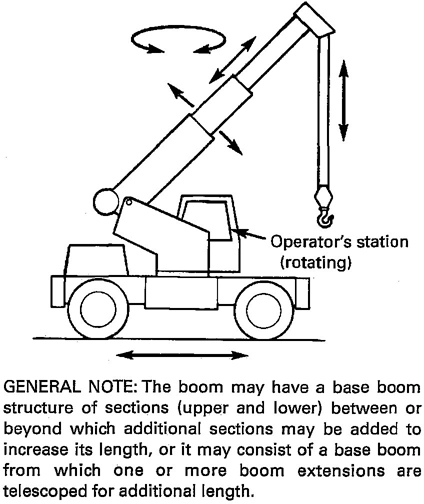
Fig. 9 Wheel-Mounted Crane — Telescoping Boom (Single Control Station, Rotating)
4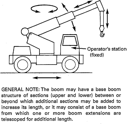
Fig. 10 Wheel-Mounted Crane—Telescoping Boom (Single Control Station, Fixed)
counterweight: weight used to supplement the weight of the machine in providing stability for lifting working loads.
crane carrier: the undercarriage of a wheel-mounted crane specifically designed for transporting the rotating crane superstructure. It may or may not provide its own travel mechanism. It is distinguished from a commercial truck vehicle in that it is not designed to transport personnel, materials, or equipment other than the crane rotating superstructure.
cross-over points: in multiple layer spooling of rope on a drum, those points of rope contact where the rope crosses the preceding rope layer.
designated person: a person selected or assigned by the employer or the employer's representative as being competent to perform specific duties.
drum: the cylindrical member around which a rope is wound for lifting and lowering the load or boom.
dynamic (loading): loads introduced into the machine or its components due to accelerating or decelerating forces.
flange point: a point of contact between rope and drum flange where the rope changes layers.
gantry (A-frame): a structural frame, extending above the superstructure, to which the boom support ropes are reeved.
hoist mechanism: a hoist drum and rope reeving system used for lifting and lowering loads.
jib: an extension attached to the boom point to provide added boom length for lifting specified loads. The jib may be in line with the boom or offset to various angles in the vertical plane of the boom.
jib backstop: a device that will restrain the jib from turning over backward.
jobsite: work area defined by the construction contract.
load (working): the external load in pounds (kilograms) applied to the crane, including the weight of load-at-teaching equipment such as lower load block, shackles, and slings.
load block, lower: the assembly of hook or shackle, swivel, sheaves, pins, and frame suspended by the hoisting ropes.
load block, upper: the assembly of shackle, swivel, sheaves, pins, and frame suspended from the boom point.
load indicator: a device that measures the weight of the load.
load ratings: crane ratings in pounds (kilograms) established by the manufacturer in accordance with Section 5-1.1.
luffing attachment: a front end attachment for a mobile crane that uses an upper working boom or jib, which is capable of changing angle during operation and is mounted on top of a lower main boom. This is distinguished from a fixed jib where the operating angle cannot be changed during operation. Typically, the lower boom operating angle can also be changed.
mast (boom): a frame hinged at or near the boom hinge for use in connection with supporting a boom. The head of the mast is usually supported and raised or lowered by the boom hoist ropes.
mast (jib): a frame hinged at or near the boom point for use in connection with supporting a jib.
normal operating conditions
cab-or station-operated cranes: conditions during which a crane is performing functions within the manufacturer's operating recommendations. Under these conditions, the operator is at the operating control devices on the crane; no other persons, except those appointed, are to be on the crane.
ground-or floor-operated cranes: conditions during which a crane is performing functions within the manufacturer's operating recommendations. Under these conditions, the operator is at the operating control devices that are mounted to the crane but operated with the operator off the crane; no other persons, except those appointed, are to be on the crane.
remote-operated cranes: conditions during which a crane is performing functions within the manufacturer's operating recommendations. Under these conditions, the operator is at the operating control devices that are not mounted to any part of the crane; no other persons, except those appointed, are to be on the crane.
5operational aid: an accessory that provides information to facilitate operation of a crane or that takes control of particular functions without action of the operator when a limiting condition is sensed. Examples of such devices include, but are not limited to, the following: anti-two-block device, rated capacity indicator, rated capacity (load) limiter, boom angle or radius indicator, lattice boom hoist disconnect device, boom length indicator, crane level indicator, drum rotation indicator, load indicator, and wind speed indicator.
outriggers: extendable or fixed members attached to the mounting base, which rest on supports at the outer ends used to support the crane.
pawl (dog): a device for positively holding a member against motion in one or more directions.
payload: that load or loads being transported by the commercial truck chassis from place to place.
pendant: a rope or strand of specified length with fixed end connections.
power-controlled lowering: a system or device in the power train, other than the load hoist brake, that can control the lowering rate of speed of the load hoist mechanism.
qualified operator: an operator who has met the requirements of paras. 5-3.1.2(a) through (c).
qualified person: a person who, by possession of a recognized degree in an applicable field or certificate of professional standing, or who, by extensive knowledge, training, and experience, has successfully demonstrated the ability to solve or resolve problems relating to the subject matter and work.
rail clamp: a tong-like metal device mounted on a locomotive crane car, which can be connected to the track.
rated capacity indicator: a device that automatically monitors radius, load weight, and load rating and warns the crane operator of an overload condition.
rated capacity (load) limiter: a device that automatically monitors radius, load weight, and load rating and prevents movements of the crane, which would result in an overload condition.
reeving: a rope system in which the rope travels around drums and sheaves.
repetitive pickup point: when operating on a short cycle operation, the rope being used on a single layer and being spooled repetitively over a short portion of the drum.
rope: refers to wire rope unless otherwise specified.
rotation-resistant rope: a wire rope consisting of an inner layer of strand laid in one direction covered by a layer of strand laid in the opposite direction. This has the effect of counteracting torque by reducing the tendency of the finished rope to rotate.
running rope: a rope that travels around sheaves or drums.
shall: the term used to indicate that the rule is mandatory and must be followed.
should: the term used to indicate that the rule is a recommendation, the advisability of which depends on the facts in each situation.
side loading: a load applied to an angle to the vertical plane of the boom.
stabilizer: stabilizers are extendable or fixed members attached to the mounting base to increase the stability of the crane, but that may not have the capability of relieving all of the weight from wheels or tracks.
standby crane: a crane that is not in regular service but that is used occasionally or intermittently as required.
standing (guy) rope: a supporting rope that maintains a constant distance between the points of attachment to the two components connected by the rope.
structural competence: the ability of the machine and its components to withstand the stresses imposed by applied loads.
superstructure: the rotating upper frame structure of the machine and the operating machinery mounted thereon.
swing: rotation of the superstructure for movement of loads in a horizontal direction about the axis of rotation.
swing mechanism: the machinery involved in providing rotation of the superstructure.
swivel: a load-carrying member with thrust bearings to permit rotation under load in a plane perpendicular to the direction of the load.
swiveling: the rotation of the load attachment portion (hook or shackle) of a load block (lower) or hook assembly about its axis of suspension in relation to the load line(s).
tackle: an assembly of ropes and sheaves arranged for lifting, lowering, or pulling.
telescoping boom: consists of a base boom from which one or more boom sections are telescoped for additional length.
transit: the moving or transporting of a crane from one jobsite to another.
travel: the function of the machine moving under its own power from one location to another on a jobsite.
two-block damage prevention feature: a system that will stall when two-blocking occurs without causing damage to the hoist rope or crane machinery components.
two-block warning feature: a warning device to alert the operator of an impending two-blocking condition.
two-blocking: the condition in which the lower load block or hook assembly comes in contact with the upper load block or boom point sheave assembly.
6wheel base: the distance between centers of front and rear axles. For a multiple axle assembly the axle center for wheel base measurement is taken as the midpoint of the assembly.
whipline (runner or auxiliary): a secondary rope system usually of lighter load capacity than that provided by the main rope system.
winch head: a power-driven spool for handling loads by means of friction between fiber or wire rope and the spool.
The following is a list of publications referenced in this Standard.
ANSI A1264.1-1989, Safety Requirements for Workplace Floor and Wall Openings, Stairs, and Railing Systems
ANSI Z26.1-1983, Safety Code for Glazing Materials for Glazing Motor Vehicles Operating on Land Highways
Publisher: American National Standards Institute (ANSI), 11 West 42nd Street, New York, NY 10036
ANSI/AWS D1.1-1988, Structural Welding Code—Steel1
ANSI/AWS D14.3-1982, Welding Specifications for Earth Moving and Construction Equipment1
Publisher: American Welding Society (AWS), 550 N.W. LeJeune Road, Miami, FL 33135
ANSI/SAE J185-JUN81, Access Systems for Off-Road Machines1
ANSI/SAE J765-OCT80, Crane Load Stability Test Code1
ANSI/SAE J983-OCT80, Crane and Cable Excavator Basic Operating Control Arrangements1
ANSI/SAE J987-OCT80, Crane Structures — Method of Test1
ANSI/SAE J1026-JUN82, Braking Performance — In-Service Crawler Tractors and Crawler Loaders1
ANSI/SAE J1028-OCT80, Mobile Crane Working Area Definitions1
ANSI/SAE J1063-OCT80, Cantilevered Boom Crane Structures — Method of Test1
Publisher: Society of Automotive Engineers (SAE), 400 Commonwealth Drive, Warrendale, PA 15096
ASME B30.8-1988, Floating Cranes and Floating Derricks1
ASME B30.9-1990, Slings1
ASME B30.10-1987, Hooks1
ASME B30.23-1998, Personnel Lifting Systems1
Publisher: The American Society of Mechanical Engineers (ASME), Three Park Avenue, New York, NY 10016-5990; Order Department: 22 Law Drive, Box 2300, Fairfield, NJ 07007-2300
U.S. DOT Safety Appliance Standards and Power Brakes Requirements (January 1973, Revised and September 1977), DOT Standards, Federal Railroad Administration, United States Department of Transportation (DOT)
Publisher: Superintendent of Documents, Washington, DC
1 May also be obtained from the American National Standards Institute, 11 West 42nd Street, New York, NY 10036.
7(a) The margin of stability for determination of load ratings, with booms of stipulated lengths at stipulated working radii for the various types of crane mountings, is established by taking a percentage of the loads that will produce a condition of tipping or balance with the boom in the least stable direction relative to the mounting. With the indicated types of mounting under conditions stipulated in paras. 5-1.1.1(b) and (c), the load ratings shall not exceed the percentages for cranes given in Table 1.
(b) The following stipulations shall govern the application of the values in para. 5-1.1.1(a) for locomotive cranes:
(1) The crane shall be standing on a track that is level within 1% grade.
(2) The radius of the load is the horizontal distance from a projection of the axis of rotation to the rail support surface, before loading, to the center of the vertical hoist line or tackle with load applied.
(3) Tipping loads from which ratings are determined shall be applied under static conditions only, i.e., without the dynamic effect of lifting, lowering, swinging, or booming.
(4) The weight of all auxiliary handling devices such as lower load block, hooks, and slings shall be considered as part of the load.
(c) Stipulations governing the application of the values in para. 5-1.1.1(a) shall be in accordance with ANSI/SAE J765.
(d) The effectiveness of these preceding stability factors will be influenced by such additional factors as freely suspended loads, track, wind, or ground conditions, condition and inflation of rubber tires, boom lengths, proper operating speeds for existing conditions, and, in general, careful and competent operation. Any standard attachments to the boom such as jibs and auxiliary or whip lines shall be considered as affecting stability and a deduction shall be made from load ratings in accordance with the manufacturer's instructions. The effect of lights, pile lead adaptors, or other nonstandard attachments shall also be deducted from load ratings. All of these shall be taken into account.
(e) When cranes included in the scope of B30.5 are mounted on barges or pontoons, factors in addition to
| Type of Crane Mounting | Maximum Load Ratings, % |
|---|---|
| Locomotive, without outrigger (stabilizer) support [Note (1)] | |
| Booms 60 ft (18 m) or less | 85 |
| Booms over 60 ft (18 m) | 85 [Note (2)] |
| Locomotive, using outriggers (stabilizers) fully extended and set | 80 |
| Crawler, without outrigger support | 75 |
| Crawler, using outriggers fully extended and set | 85 |
| Wheel mounted, without outrigger support | 75 |
| Wheel mounted, using outrigger fully extended and set, with tires off supporting surface | 85 |
| Wheel mounted, using outrigger beams partially extended and set, with tires off supporting surface | Notes (3) and (4) |
| Commercial truck vehicle mounted, with stabilizers extended and set | 85 |
| Commercial truck mounted, using stabilizers partially extended and set | Notes (3) and (4) |
NOTES:
|
|
those stipulated in paras. 5-1.1.1 and 5-1.1.2 will influence the stability and structural competence. The load rating for a crane on a barge or pontoon shall be modified as recommended by the manufacturer or a qualified person (refer to ASME B30.8).
8(a) Load ratings for some radii are limited by the stability of the crane. However, in some of the operating ranges the rating may be limited by factors other than stability, such as the conditions described below.
(1) The loads that will produce a condition of tipping increase rapidly and reach extreme values as the minimum operating radius and tipping fulcrum of the machine are approached. At some radii, these loads are of such magnitude that they cannot be fully taken into account in the crane structure design without excessive weight, which would severely limit performance and ratings at the longer radii where most work is done. Hence, load ratings at some radii may be based on structural competence of the machine rather than stability.
(2) A nonsymmetrical mounting requires a higher loading to produce a condition of tipping in a direction other than that of least stability on which the load ratings are established. Therefore, if the crane specification includes additional ratings for directions other than the least stable, such ratings may also be governed by structural competence rather than stability. For such specified additional ratings, the work area shall be indicated; for those ratings that might be governed by tipping loads, the applicable percentage factors in para. 5-1.1.1(a) shall not be exceeded.
(b) For all operational applications, the crane load ratings established by the manufacturer shall not be exceeded (refer to para. 5-3.2.1).
(a) A durable rating chart(s) with legible letters and figures shall be provided with each crane and attached in a location accessible to the operator while at the controls. The data and information to be provided on these charts shall include, but not be limited to, the following:
(1) A full and complete range of manufacturer's crane load ratings at all stated operating radii, boom angles, work areas, boom lengths and configurations, jib lengths and angles (or offset), as well as alternate ratings for use and nonuse of optional equipment on the crane, such as outriggers and extra counterweights, which affect ratings.
(2) A work area chart for which capacities are listed in the load rating chart (see Fig. 11).2
(3) Where ratings are limited by structural, hydraulic, or factors other than stability, the limitations shall be shown and emphasized on the rating charts.
(4) In areas where no load is to be handled, the work area figure and load rating chart shall so state.
(5) Recommended reeving for the hoist lines shall be shown.
(b) In addition to the data required on the load rating chart, the following information shall be shown either on the rating chart or in the operating manual:
(1) recommended parts of hoist reeving, size, and type of rope for various crane loads
(2) recommended boom hoist reeving diagram, where applicable; size, type, and length of rope
(3) tire pressure, where applicable
(4) cautionary or warning notes relative to limitations on equipment and operating procedures, including indication of the least stable direction
(5) position of the gantry and requirements for intermediate boom suspension, where applicable
(6) instructions for boom erection and conditions under which the boom, or boom and jib combinations, may be raised or lowered
(7) whether the hoist holding mechanism is automatically controlled, manually controlled, whether free-fall is available, or any combination thereof
(8) the maximum telescopic travel length of each boom telescopic section
(9) whether sections are telescoped with power or manually
(10) the sequence and procedure for extending and retracting the telescopic boom section
(11) maximum loads permitted during the actual boom extending operation, and any limiting conditions or cautions
(12) hydraulic relief valve settings specified by the manufacturer
The backward stability of a crane is its ability to resist overturning in the direction opposite the boom point while in the unloaded condition. The resistance to backward overturning is reflected in the margin of backward stability.
The general conditions for the determination of the backward stability margin, applicable to all cranes within the scope of this chapter, are as follows:
(a) crane to be equipped for crane operation with shortest recommended boom
(b) boom positioned at maximum recommended boom angle
(c) crane to be unloaded (lower load block on support)
(d) outriggers free of the bearing surface when the crane is counterweighted for “on tires or on wheels“ operation unless specified by the manufacturer for stationary use
2 Sketches (a) through (d) or Fig. 11 are reproduced from ANSI/SAE J1028, Recommended Practice, by permission of the Society of Automotive Engineers, Inc.
9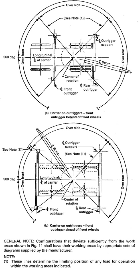
Fig. 11 Work Areas
10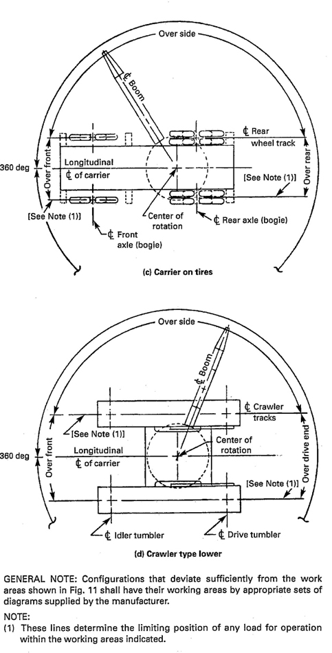
Fig. 11 Work Areas (Cont’d)
11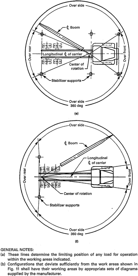
Fig. 11 Work Areas (Cont’d)
12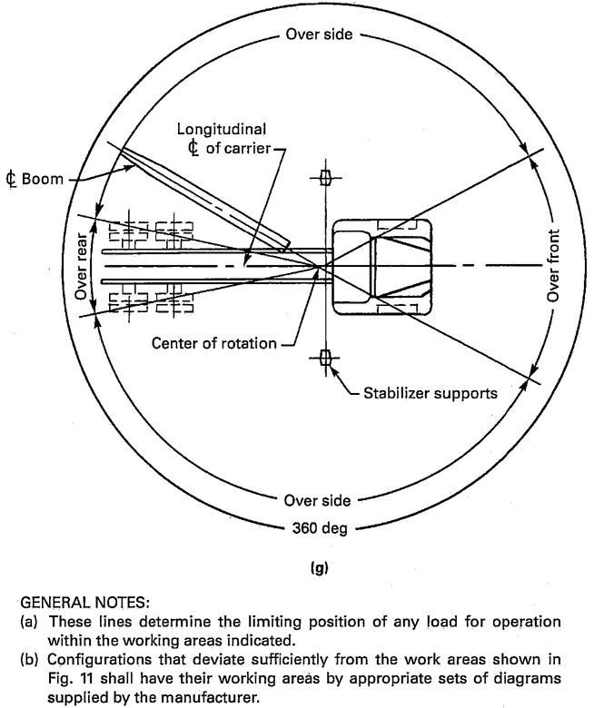
Fig. 11 Work Areas (Cont’d)
(e) crane to be standing on a firm supporting surface, level within 1% grade; locomotive cranes to be standing on a level track
(f) all fuel tanks to be at least half full and all other fluid levels as specified
The following are minimum acceptable backward stability conditions:
(a) Locomotive Cranes. The horizontal distance between the center of gravity of the crane and the axis of rotation shall not exceed 39% of the track gage.
(b) Crawler Cranes. The horizontal distance between the center of gravity of the crane and the axis of rotation shall not exceed 70% of the radial distance from the axis of rotation to the backward tipping fulcrum in the least stable direction.
(c) Wheel-Mounted Cranes (Counterweighted for “on Tires or on Wheels” Operation)
(1) With the longitudinal axis of the rotating super-structure of the crane at 90 deg to the longitudinal axis of the carrier, the total load on all wheels on the side of the carrier under the boom shall not be less than 15% of the total weight of the crane.
(2) With the longitudinal axis of the rotating super-structure of the crane in line with the longitudinal axis of the carrier in either direction, the total load on all wheels under the lighter loaded end of the carrier shall not be less than 15% of the total weight of the crane in the manufacturer's specified work area and not be less than 10% of the total weight of the crane in an area not specified as a work area (see Fig. 11).
(d) Wheel-Mounted Cranes (Counterweighted for “on Outrigger” Operation). Under the conditions of paras. 5-1.2.2(a), (b), (c), (e), and (f), and with the machine supported level on fully extended outriggers with all tires free of the supporting surface, the resistance to overturning in a backward direction shall be equivalent
13to those conditions specified in paras. 5-1.2.3(c)(1) and (2).
Cranes may not have sufficient forward stability (in the direction of the boom) to handle some boom lengths. Information shall be provided on the load rating chart stating any limitations in boom length or boom angle for specified operating conditions of outriggers, direction of boom, or other requirements.
The boom hoist may use a rope drum for its drive or hydraulic cylinder(s), and the supporting structure may be a gantry or the same hydraulic cylinder(s) used to elevate the boom.
(a) The boom hoist shall be capable of elevating and controlling the boom with its rated load (for rope boom hoists when reeved according to the manufacturer's specifications) and shall be capable of supporting the boom and rated load without action by the operator.
(b) In a rope-supporting and elevating arrangement, boom lowering shall be done only under power control. Free-fall lowering of the boom shall not be permitted.
(1) The boom hoist drum shall have sufficient rope capacity to operate the boom in all positions, from the lowest permissible to the highest recommended, when using the manufacturer's recommended reeving and rope size. No less than two full wraps of rope shall remain on the drum with the boom point lowered to the level of the crane-supporting surface. The drum end of the rope shall be anchored to the drum by an arrangement specified by the crane or rope manufacturer.
(2) The drum shall provide a first layer rope pitch diameter of not less than 15 times the nominal diameter of the rope used.
(c) On rope boom support machines, a braking mechanism and a ratchet and pawl or other locking device shall be provided to prevent inadvertent lowering of the boom.
(d) An integrally mounted holding device (such as a load hold check valve) shall be provided with boom support hydraulic cylinder(s) to prevent uncontrolled lowering of the boom in the event of a hydraulic system failure (e.g., supply hose rupture).
The hoist mechanism may consist of a drum or hydraulic cylinder(s) with necessary rope reeving.
(a) Load Hoist Drums. The load hoist drum assemblies shall have power and operational characteristics sufficient to perform all load lifting and lowering functions required in crane service when operated under recommended conditions.
(1) Where brakes and clutches are used to control the motion of the load hoist drums, they shall be of a size and thermal capacity sufficient to control all rated crane loads with minimum recommended reeving (where maximum rated loads are being lowered with near maximum boom length or operations involving long lowering distances, power-controlled lowering is usually desirable to reduce demand on the load brake). Brakes and clutches shall be provided with adjustments where necessary to compensate for lining wear and to maintain force in springs, where used.
(2) Load hoist drums shall have rope capacity with the recommended rope size and reeving sufficient to perform crane service within the range of boom lengths, operating radii, and vertical lifts specified by the manufacturer.
(a) No less than two full wraps of rope shall remain on the drum when the hook is in the extreme low position.
(b) The drum end of the rope shall be anchored to the drum by an arrangement specified by the crane or rope manufacturer.
(c) The drum flange shall extend a minimum of ½ in. (13 mm) over the top layer of rope at all times.
(3) The load hoist drums shall provide a first layer rope pitch diameter of not less than 18 times the nominal diameter of the rope used.
(4) A means controllable from the operator's station shall be provided to hold the drum from rotating in the lowering direction and be capable of holding the rated load without further action by the operator. Foot-operated brakes having a continuous mechanical linkage between the actuating and braking means, capable of transmitting full braking force, and equipped with a positive mechanical means to hold the linkage in the applied position, meet this requirement.
(5) Drum rotation indicators should be provided and located to afford sensing by the operator.
(b) Load Hoist Brakes
(1) When power-operated brakes having no continuous mechanical linkage between the actuating and braking means are used for controlling loads, an automatic means shall be provided to set the brake to prevent the load from falling in the event of loss of brake control power.
(2) Foot-operated brake pedals shall be constructed so that the operator's feet, when in proper position, will not slip off, and a means shall be provided for holding the brakes in the applied position without further action by the operator.
(c) Power-Controlled Lowering. When provided, a power-controlled lowering system shall be capable of handling rated loads and speeds as specified by the manufacturer. Such a system is recommended to assist
14in precision lowering and to reduce demand on the load brake.
(d) Cylinders With Rope Reeving. Cranes using a load hoist mechanism with hydraulic cylinder(s) and rope reeving shall have power and operational characteristics sufficient to perform all load lifting and lowering functions required in crane service when operated under recommended conditions. Sheaves used in multiple rope reeving shall have a pitch diameter not less than 16 times the nominal diameter of the rope and shall comply with para. 5-1.7.4.
(a) Extension and retraction of boom sections may be accomplished through hydraulic, mechanical, or manual means.
(b) The powered retract function shall be capable of controlling any rated load that can be retracted.
(c) An integrally mounted holding device (such as a load hold check value) shall be provided with the telescopic hydraulic cylinder(s) to prevent uncontrolled retraction of the boom in the event of a hydraulic system failure (e.g., supply hose rupture).
The swing mechanism shall start and stop with controlled acceleration and deceleration.
(a) A braking means with holding power in both directions shall be provided to restrict movement of the rotating superstructure, when desired during normal operation. The braking means shall be capable of being set in the holding position and remaining so without further action by the operator.
(b) A device or boom support shall be provided to prevent the boom and superstructure from rotating when in transit. It shall be constructed to minimize inadvertent engagement or disengagement.
(a) On all crane types with a single control station, the controls for the travel function shall be located at the operator's station.
(b) On all wheel-mounted multiple control station cranes, the travel controls shall be located in the carrier cab. Auxiliary travel controls may also be provided in the crane cab. If there is an operator in the crane cab when the crane is traveling, communication shall be provided between the cabs. Use of audible signalling devices will meet this requirement.
(a) On locomotive cranes, when the travel mechanism must be temporarily deactivated in the normal course of the requirements of the user, provision shall be made to disengage the travel mechanism from the cab or outside the crane body.
(b) On a crawler crane, the travel and steering mechanism shall be arranged so that it is not possible for both crawlers to freewheel without operator control. Control shall be effected from the operator's position on the revolving superstructure.
(a) On crawler cranes, brakes or other locking means shall be provided to hold the machine stationary during working cycles on a level grade or while the machine is standing on the maximum grade recommended for travel. Such brakes or locks shall be arranged to remain in engagement in the event of loss of operating pressure or power.
(b) On locomotive cranes, brakes shall be provided to bring the crane to a stop while descending the maximum grade recommended for travel. Also, manual brake engagement means shall be provided to hold the machine stationary on the maximum grade recommended for travel. Such means shall be arranged to remain in engagement in the event of loss of operating air pressure.
(c) On wheel-mounted cranes, means shall be provided to control completely the crane carrier travel when descending maximum grades specified by the manufacturer under maximum loading conditions. Brakes shall be provided to bring the machine to a stop on level ground within a distance of 32 ft (10 m) from a speed of 15 mph (6.7 m/s). Where long or steep grades are to be negotiated, a retarder or similar device should be provided. Means shall be provided to hold the machine stationary on the maximum grade for travel recommended by the manufacturer. Where travel brakes are operated by air pressure, means shall be provided for manually or automatically stopping the vehicle when the operating pressure falls below the specified minimum level.
(d) Vehicle-mounted cranes on commercial trucks shall meet the requirements of the U.S. Department of Transportation Standards.
(a) Basic controls (see Figs. 12 and 13) used during the crane operating cycle shall be located within reach of the operator while at the operator's station.
(b) Controls for load hoist, boom hoist, swing, and boom telescope (when applicable) shall be provided
15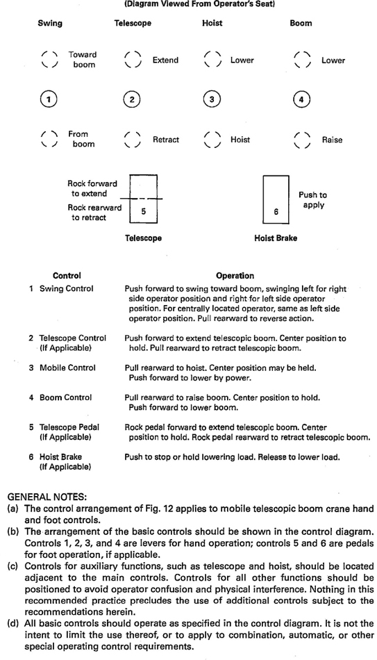
Fig. 12 Telescopic Boom Crane Control Diagram (Suggested Mobile Telescopic Boom Crane Basic Operating Control Arrangement for New Cranes)
16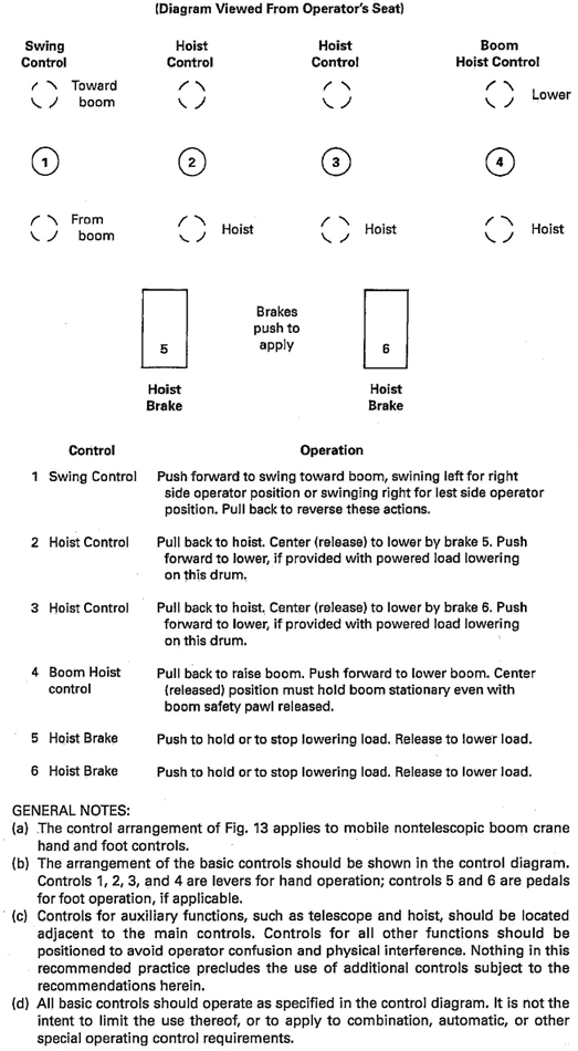
Fig. 13 Nontelescopic Boom Crane Control Diagram (Suggested Mobile Nontelescopic Boom Crane Basic Operating Control Arrangement for New Cranes)
17with means for holding in the neutral position, without the use of positive latches.
(c) On machines equipped with telescoping-type booms, the arrangements of controls should be as shown in Fig. 12. On machines not equipped with telescoping-type booms, the arrangements of controls should be as shown in Fig. 13.
(d) Remote-operated cranes shall function so that if the control signal for any crane motion becomes ineffective, the crane motion shall stop.
(e) Provisions shall be made for emergency stop in the event of a device malfunction for remote-operated cranes.
(a) Forces shall not be greater than 35 lb (156 N) on hand levers and not greater than 50 lb (222 N) on foot pedals.
(b) Travel distance on hand levers shall not be greater than 14 in. (356 mm) from neutral position on two-way levers and not greater than 24 in. (610 mm) on one-way levers. Travel distance on foot pedals shall not be greater than 10 in. (254 mm).
Controls for operating a superstructure mounted power plant shall be within reach of the operator and shall include the means to
(a) start and stop
(b) control the speed of internal combustion engines
(c) stop two-cycle diesel engines under emergency conditions
(d) shift selective transmissions
All cranes with a direct mechanical or hydrodynamic (such as torque converter or fluid coupling) drive to any crane function shall be provided with a clutch or other means for disengaging power. The controls shall be within reach of the operator's station.
(a) For supporting rated loads and for supporting the boom and working attachments at recommended travel or transit positions and boom lengths,
(1) the design factor for live or running ropes that wind on drums or travel over sheaves shall not be less than 3.5.
(2) the design factor for boom pendants or standing ropes shall not be less than 3.0.
(b) For supporting the boom under recommended boom erection conditions,
(1) the design factor for live or running ropes shall not be less than 3.0.
(2) the design factor for boom pendants or standing ropes shall not be less than 2.5.
(c) Rotation-resistant ropes shall have a design factor of 5 or greater [The design factor of 5 or greater for rotation-resistant ropes may be modified by the crane user by complying with the provisions of para. 5-3.2.1.1(d)].
(d) The design factor specified in paras. 5-1.7.1(a) through (c) shall be the total minimum breaking strength of all ropes in the system divided by the load imposed on the rope system when supporting the static weights of structure and crane rated load.
NOTE: minimum breaking strength was formerly referred to as nominal breaking strength.
(a) The ropes shall be of a construction recommended by the rope or crane manufacturer or a qualified person.
(b) Fiber core ropes shall not be used for boom hoist or luffing attachment reeving.
(c) Rotation-resistant ropes shall not be used for boom hoist reeving as normally defined in Section 5-1.3.
(d) Rotation-resistant ropes may be used as boom hoist reeving when load hoists are used as boom hoists for attachments such as luffing attachments or boom and mast attachments systems. Under these conditions, the following requirements shall be met:
(1) All the requirements of the boom hoist mechanism (see para. 5-1.3.1), with the exception of the drum, shall provide a first-layer rope pitch diameter of not less than 18 times the nominal diameter of the rope used.
(2) All the requirements of the boom hoist mechanism (see para. 5-1.3.2).
(3) All sheaves used in the boom hoist reeving system shall have a rope pitch diameter of not less than 18 times the nominal diameter of the rope used.
(4) The design factor for the boom hoist reeving system shall not be less than 5.
(5) The design factor specified in para. 5-1.7.2(d)(4) shall be the total minimum breaking force of all parts of ropes in the system divided by the load imposed on the rope system when supporting the static weights of the structure and the crane rated load.
(6) The frequency of inspection of the wire rope shall be increased when using rotation-resistant rope in boom hoist or luffing attachment service.
(e) Rotation-resistant rope shall be given special care during installation as it is easily damaged.
(f) Socketing shall be done in the manner specified by the manufacturer of the wire rope or fitting.
(g) If a load is supported by more than one part of rope, the tension in the parts shall be equalized.
18(h) Wherever exposed to ambient temperatures at the rope in excess of 180°F (82°C), rope having an independent wire-rope or wire-strand core, or other temperature damage-resistant core, shall be used.
(a) Eye splices shall be made in a manner recommended by the rope or crane manufacturer, and rope thimbles should be used in the eye.
(b) Wire rope clips shall be drop-forged steel of the single-saddle- (U-bolt) or double-saddle-type clip. Malleable cast iron clips shall not be used. For spacing, number of clips, and torque values, refer to the clip manufacturer's recommendation. Wire rope clips attached with U-bolts shall have the U-bolt over the dead end of the rope and the live rope resting in the clip saddle. Clips shall be tightened evenly to the recommended torque. After the initial load is applied to the rope, the clip nuts shall be retightened to the recommended torque to compensate for any decrease in rope diameter caused by the load. Rope clip nuts should be retightened periodically to compensate for any further decrease in rope diameter during usage.
(c) Swaged, compressed, or wedge socket fittings shall be applied as recommended by the rope, crane, or fitting manufacturer. Any new poured socket or swaged socket assembly used as a boom pendant shall be proof tested to the crane or fitting manufacturer's recommendation, but in no case greater than 50% of the nominal strength of the component wire rope or structural strand.
(d) Wire rope clips used in conjunction with wedge sockets shall be attached to the unloaded dead end of the rope only (see Fig. 14). This does not preclude the use of devices specially designed for dead ending rope in a wedge socket.
(a) Sheave grooves shall be free from surface defects that could cause rope damage. The cross-sectional radius at the bottom of the groove should be such as to form a close-fitting saddle for the size of rope used. The sides of the groove shall be tapered outward and rounded at the rim to facilitate entrance of the rope into the groove. Flange rims shall run true about the axis of rotation.
(b) Sheaves carrying ropes that can be momentarily unloaded shall be provided with close-fitting guards or other devices to guide the rope back into the groove when the load is reapplied.
(c) The sheaves in the lower load block shall be equipped with close-fitting guards that will prevent ropes from becoming fouled when the block is lying on the ground with loose ropes.
(d) All sheave bearings, except for permanently lubricated bearings, shall be provided with means for lubrication.
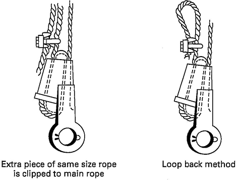
(04) Fig. 14 Dead Ending Rope in a Socket
(a) Boom-hoisting sheaves shall have pitch diameters of not less than 15 times the nominal diameter of the rope used.
(b) Load-hoisting sheaves shall have pitch diameters not less than 18 times the nominal diameter of the rope used.
(c) Load block (lower) sheaves shall have pitch diameters not less than 16 times the nominal diameter of the rope used.
Load hooks, ball assemblies, and load blocks shall be of sufficient weight to overhaul the line from the highest hook position for boom or boom and jib lengths, and the number of parts of line in use. All hook and ball assemblies and load blocks shall be labeled with their rated capacity and weight. Hooks shall be equipped with latches unless the application makes the use of a latch impractical. When provided, the latch shall bridge the throat opening of the hook for the purpose of retaining slings or other lifting devices under slack conditions (refer to ASME B30.10).
(a) Insofar as is practical, all cabs and enclosures shall be constructed to protect the superstructure machinery, brakes, clutches, and operator's station from the weather.
(b) All cab glazing shall be safety glazing material as defined in ANSI Z26.1. Windows shall be provided in the front and on both sides of the cab or operator's compartment with visibility forward and to either side. Visibility forward shall include a vertical range adequate.
19to cover the boom point at all times. The front window may have a section that can be readily removed or held open, if desired. If the section is of the type held in the open position, it shall be secured to prevent inadvertent closure. A windshield wiper should be provided on the front window.
(c) All cab doors, whether of the sliding or swinging type, shall be restrained from inadvertent opening or closing while traveling or operating the machine. The door adjacent to the operator, if of the swinging type, should open outward and, if of the sliding type, should slide rearward to open.
(d) A clear passageway shall be provided from the operator's station to an exit door on the operator's side.
(e) A seat belt shall be provided in all single-control-station, wheel-mounted cranes for use during transit and travel.
(a) Principal walking surfaces shall be of a skid-resistant type.
(b) Outside platforms, if furnished, shall be provided with guardrails in accordance with ANSI/SAE J185. Where platforms are too narrow to use guardrails, handholds shall be provided at convenient points above the platform.
(a) On locomotive cranes, handholds and steps shall be provided for access to the car and cab. Their construction shall conform to the requirements of the Safety Appliance Standards and Power Brakes Requirements of the Federal Railroad Administration.
(b) On all crawler and wheel-mounted cranes, handholds, steps, or both shall be provided, as needed, to facilitate entrance to and exit from the operator's cab and the carrier cab.
(c) Principal walking surfaces shall be of a skid-resistant type.
Where necessary for rigging or service requirements, a ladder or steps shall be provided to give access to the cab roof. The ladder or steps shall conform to the requirements of ANSI/SAE J185. Where necessary, areas of the cab roof shall be capable of supporting, without permanent distortion, the weight of a 200 1b (90 kg) person.
(a) Boom Stops. Stops shall be provided to resist the boom falling backwards. Boom stops should be of one of the following types:
(1) a fixed or telescoping bumper
(2) a shock-absorbing bumper
(3) hydraulic boom elevation cylinder(s)
(b) Jibs shall be restrained from backward over-turning.
(c) A boom angle or radius indicator readable from the operator's station shall be provided.
(d) A boom hoist disconnect, shutoff, or hydraulic relief shall be provided to automatically stop the boom hoist when the boom reaches a predetermined high angle.
(e) A boom length indicator readable from the operator's station shall be provided for telescoping booms unless the load rating is independent of the boom length.
(f) Booms, boom sections, and jibs shall be identified and shall be used only for the purposes recommended by the manufacturer.
Engine exhaust gases shall be piped to the outside of the cab and discharged in a direction away from the operator. All exhaust pipes shall be guarded or insulated to prevent contact with personnel when performing normal duties.
(a) Means shall be provided to hold all outriggers in the retracted position while traveling and in the extended position when set for operating.
(b) Power-actuated jacks, where used, shall be provided with the means (such as integral load hold check valves on hydraulic cylinders, mechanical locks, etc.) to prevent loss of support under load.
(c) Means shall be provided for fastening outrigger floats to outriggers when in use.
(04) (d) Partially Extended Outrigger Beams, Outrigger Beam Position
(1) A device or system shall be provided that accurately locates the outrigger beam(s) to coincide with the partially extended outrigger position(s) on the load capacity chart.
(2) Visible indication of the manufacturer's specified outrigger positions shall be provided by means such as stripes painted on the outrigger beams or an electronic display.
(a) Truck Wedges or Jacks. Locomotive crane cars shall be provided with removable wedges or jacks for transmitting loads from the crane body directly to the wheels without permitting the truck springs to function when handling heavy loads. These wedges shall be removable, or the jacks releasable, in a manner positive for transit.
(b) Truck Center Pins. Each truck center pin shall be provided with a connecting means, such as a king bolt, to permit truck weight to contribute to crane stability.
20All welding procedures and welding operator qualifications shall be in accordance with ANSI/AWS D14.3 when welding is to be performed on load-sustaining members. Where special steels or other materials are used, the manufacturer shall provide welding procedures.
(a) Exposed moving parts (such as gears, set screws, projecting keys, chains, chain sprockets, and reciprocating or rotating parts) that might constitute a hazard under normal operating conditions shall be guarded.
(b) Guards shall be fastened and shall be capable of supporting, without permanent distortion, the weight of a 200 lb (90 kg) person unless the guard is located where it is impossible for a person to step on it.
Dry friction brakes and clutches shall be protected against rain and other liquids such as oil and lubricants.
Exposed lines subject to damage shall be protected in so far as it is practical.
The crane and/or device manufacturer’ instructions shall describe the purpose of the device. The crane and/or device manufacturer shall provide recommendations for continued operation or shutdown of the crane if operational aids are inoperative or malfunctioning. Without such recommendations and any prohibitions from the manufacturer against further operation, the requirements of para. 5-3.2.1.2(b) shall apply.
5-1.9.9.1 Two-blocking Features
(a) Telescopic boom cranes shall be equipped with an anti-two-block device or a two-block damage prevention feature for all points of two-blocking (i.e., jibs, extensions; see Section IV, New and Existing Installations).
(b) Lattice boom cranes shall be equipped with an anti-two-block device or a two-block warning feature that functions for all points of two-blocking (see Section IV, New and Existing Installations).
5-1.9.9.2 Load Indicators, Rated Capacity Indicators, and Rated Capacity Limiters. All cranes with a maximum rated load capacity of 3 tons or more shall have a load indicator, rated capacity indicator, or rated capacity (load) limiter (see Section IV, New and Exisiting Installations).
5-1.9.9.3 For boom angle or radius indicator, see para. 5-1.9.1(c).
5-1.9.9.4 For boom hoist disconnect, shutoff, or hydraulic relief, see para. 5-1.9.1(d).
5-1.9.9.5 For boom length indicator, see para. 5-1.9.1(e).
5-1.9.9.6 For crane level indicator, see para. 5-1.9.11(d).
5-1.9.9.7 For drum rotation indicator, see para. 5-1.3.2(a)(5).
Lubricating points should be accessible without the necessity of removing guards or other parts.
(a) The fuel tank filler pipe shall be located or protected so as not to allow spill or overflow to run onto the engine, exhaust, or electrical equipment of the machine being fueled.
(b) Toolbox. A metal receptacle should be secured to the crane for storing tools and lubricating equipment.
(c) An audible signal device shall be provided. The control for the device shall be within reach of the operator (refer to para. 5-3.3.4).
(d) Means shall be provided for the operator to visually determine the levelness of the crane.
(e) Hydraulic relief valves used to limit maximum pressure developed within the hydraulic system shall have pressure settings to permit operation under rated loading conditions and also to meet the requirements of para. 5-1.3.1(a).
(f) Means shall be provided for checking the manufacturer's specified pressure settings in each hydraulic circuit.
(g) A sign shall be installed, visible from the operator's station, warning that electrocution or serious bodily injury may occur, unless a minimum clearance of 10 ft (3m) is maintained between the crane or load for energized power lines up to 50 kV, and that greater clearances are required for higher voltages [refer to para. 5-3.4.5(a)(1)].
(a) Prototype booms, jibs, gantries, masts, outriggers, carrier frames, and upper frames of production models of rope-supported lattice boom cranes shall meet the performance requirements of ANSI/SAE J987. On special designs (not production models) or specific lift situations, calculations that verify the equipment's ability to meet the performance requirements of ANSI/SAE J987, done by the crane manufacturer or a qualified person, are acceptable.
(b) Prototype booms, jibs, masts, lattice extensions (jibs), outriggers, carrier frames, and upper frames of production models of telescopic cantilever boom cranes shall meet the performance requirements of ANSI/SAE J1063. On special designs (not production models) or
21specific lift situations, calculations that verify the equipment's ability to meet the performance requirements of ANSI/SAE J1063, done by the crane manufacturer or a qualified person, are acceptable.
(a) When cranes within the scope of this volume are used for service other than lifting service, the manufacturer or (when not available from the manufacturer) a qualified person shall establish the ratings, operating limitations, maintenance, testing, and inspection requirements that apply during that use. The manufacturer or qualified person shall consider, as minimum requirements, the maintenance, testing, and inspection requirements in Chapter 5-2 and the conduct of operators provisions in Section 5-3.1.
(b) Documentation supporting the ratings, operating limitations, maintenance, testing, and inspection requirements of para 5-1.11.1 shall be maintained.
22The manufacturer shall furnish required field assembly, operation, and maintenance information.
(a) Initial Inspection. Prior to initial use, all new and altered cranes shall be inspected by a qualified person to verify compliance with the provisions of this volume.
(b) Regular Inspection. Inspection procedure for cranes in regular service is divided into two general classifications based on the intervals at which inspection should be performed. The intervals depend on the nature of the critical components of the crane and the degree of their exposure to wear, deterioration, or malfunction. The two general classifications are herein designated as frequent and periodic, with respective intervals between inspections as defined.
(1) Frequent Inspection. Daily to monthly intervals by a designated person.
(2) Periodic Inspection. One to 12-months intervals, or as specifically recommended by the manufacturer or a qualified person.
Items such as the following shall be inspected by a designated person for defects at intervals as defined in para. 5-2.1.1(b)(1) or as specifically indicated by the manufacturer, including observation during operation for any deficiencies that might appear between regular inspections. Any deficiencies shall be carefully examined and a determination made as to whether they constitute a hazard.
(a) All control mechanisms for maladjustment interfering with proper operation: daily, when used.
(b) All control mechanisms for excessive wear of components and contamination by lubricants or other foreign matter.
(c) Operational aids for malfunction: daily, when used.
(d) All hydraulic hoses, particularly those that flex in normal operation of crane functions, should be visually inspected once every working day, when used.
(e) Hooks and latches for deformation, chemical damage, cracks, and wear (refer to ASME B30.10).
(f) Rope reeving for compliance with crane manufacturer's specifications.
(g) Electrical apparatus for malfunctioning, signs of excessive deterioration, dirt, and moisture accumulation.
(h) Hydraulic system for proper oil level: daily, when used.
(i) Tires for recommended inflation pressure.
Complete inspections of the crane shall be performed by a qualified person at intervals as generally defined in para. 5-2.1.1(b)(2), depending on the crane's activity, severity of service, and environment, or as specifically indicated below. These inspections shall include the requirements of para. 5-2.1.2 and items such as the following. Any deficiencies shall be examined and determination made as to whether they constitute a hazard.
(a) deformed, cracked, or corroded members in the crane structure and entire boom
(b) loose bolts or rivets
(c) cracked or worn sheaves and drums
(d) worn, cracked, or distorted parts such as pins, bearings, shafts, gears, rollers, and locking devices
(e) excessive wear on brake and clutch system parts, linings, pawls, and rachets
(f) any significant inaccuracies of operational aids [refer to para. 5-2.6(b)]
(g) lack of performance and compliance with safety requirements of gasoline, diesel, electric, or other power plants
(h) excessive wear of chain drive sprockets and excessive chain stretch
(i) cracked crane hooks
(j) malfunctioning travel steering, braking, and locking devices
(k) excessively worn or damaged tires
(l) hydraulic and pneumatic hose, fittings, and tubing
(1) evidence of leakage at the surface of the flexible hose or its junction with the metal and couplings.
(2) blistering or abnormal deformation of the outer covering of the hydraulic or pneumatic hose.
(3) leakage at threaded or clamped joints that cannot be eliminated by normal tightening or recommended procedures.
(4) evidence of excessive abrasion or scrubbing on the outer surface of a hose, rigid tube, or fitting. Means shall be taken to eliminate the interference of elements in contact or otherwise protect the components.
23(m) hydraulic and pneumatic pumps and motors
(1) loose bolts or fasteners
(2) leaks at joints between sections
(3) shaft seal leaks
(4) unusual noises or vibration
(5) loss of operating speed
(6) excessive heating of the fluid
(7) loss of pressure
(n) hydraulic and pneumatic valves
(1) cracks in valve housing
(2) improper return of spool to neutral position
(3) leaks at spools or joints
(4) sticking spools
(5) failure of relief valves to attain correct pressure setting
(6) relief valve pressures as specified by the manufacturer
(o) hydraulic and pneumatic cylinders
(1) drifting caused by fluid leaking across the piston
(2) road seals leakage
(3) leaks at welded joints
(4) scored, nicked, or dented cylinder rods
(5) dented case (barrel)
(6) loose or deformed rod eyes or connecting joints
(p) hydraulic filters
(1) evidence of rubber particles on the filter element, which may indicate hose, “O” ring, or other rubber component deterioration. Metal chips or pieces on the filter may denote failure in pumps, motors, or cylinders. Further checking will be necessary to determine the origin of the problem before corrective action can be taken.
(a) A crane that has been idle for a period of 1 month or more, but less than 6 months, shall be given an inspection by a qualified person conforming with the requirements of paras. 5-2.1.2 and 5-2.4.2(a) before being placed in service.
(b) A crane that has been idle for a period of over 6 months shall be given a complete inspection by a qualified person conforming with the requirements of paras 5-2.1.2, 5-2.1.3, and 5-2.4.2 before being placed in service.
(c) Standby cranes shall be inspected by a qualified person at least semiannually in accordance with the requirements of paras. 5-2.1.2 and 5-2.4.2(a). Cranes that are exposed to adverse environmental conditions should be inspected more frequently.
Dated records for periodic inspections shall be made on critical items such as brakes, crane hooks, ropes, hydraulic and pneumatic cylinders, and hydraulic and pneumatic relief pressure valves. Records should be kept where they are available to appointed personnel.
(a) Prior to daily operation, operational aids shall be checked in accordance with the device/crane manufacturer's recommended procedures to determine if they are functioning properly.
(b) Operational aids shall be inspected and tested by a qualified person in accordance with the device/crane manufacturer's recommended procedures as part of the periodic inspection of para. 5-2.1.3.
(04) (c) When operational aids are inoperative or malfunctioning, the crane and/or device manufacturer's recommendations for continued operation or shutdown of the crane shall be followed until the problems are corrected [refer to para. 5-3.2.1.2(b)(1)]. Without such recommendations and any prohibitions from the manufacturer against further operation, the requirements of para. 5-3.2.1.2(b) shall apply.
(a) Each new production crane shall be tested by the manufacturer to the extent necessary to ensure compliance with the operational requirements of this section, including for functions such as the following:
(1) load lifting and lowering mechanisms
(2) boom lifting and lowering mechanisms
(3) boom extension and retraction mechanism
(4) swinging mechanism
(5) travel mechanism
(6) safety devices
(04) (7) operational aids
(b) Where the complete production crane is not supplied by one manufacturer, such tests shall be conducted at final assembly.
(c) Operational crane test results shall be made available.
(a) Prior to initial use, all cranes in which load-sustaining parts have been altered, replaced, or repaired should be load tested by, or under the direction of, a qualified person. The replacement of the rope is specifically excluded from this requirement. However, a functional test of the crane under a normal operating load should be made prior to putting the crane back in service.
(1) Test loads shall not exceed 110% of the manufacturer's load rating.
(2) Written reports that show test procedures and confirm the adequacy of repairs or alterations shall be furnished by an appointed or authorized person.
(3) Operational aids that function to restrict the capacity of the crane may be temporarily overridden
24during the performance of the rated load test, if required, to handle the test load.
(b) Where rerating is necessary:
(1) Crawler and wheel-mounted cranes shall be tested in accordance with paras. 5-1.1.1(a) and 5-1.1.1(c) for load ratings where stability governs. Ratings governed by structural competence shall be established by the manufacturer or a qualified person and tested to 110% of the rating.
(2) Locomotive cranes shall be tested in accordance with paras. 5-1.1.1(a) and 5-1.1.1(b) of this volume.
(3) The rerating test report shall be made available.
(4) No crane shall be rerated in excess of the original load ratings unless such rating changes are approved by the crane manufacturer or a qualified person.
(c) If a Rated Load Test is required by an administrative or regulatory authority, the crane shall be tested in accordance with paras. 5-2.2.2(a) and (b).
(04) (a) A preventive maintenance program shall be established and should be based on the recommendations outlined in the crane manufacturer's manual. If a qualified person determines it is appropriate, the program should also include that individual′s additional recommendations based on a review of the crane application and operations. Dated records should be placed on file.
(b) It is recommended that replacements parts be obtained from the original equipment manufacturer.
(a) Before adjustments and repairs are started on a crane, the following precautions shall be taken as applicable:
(1) Place crane where it will cause the least interference with other equipment or operations in the area.
(2) Set all controls in the off position and ensure all operating features are secured from inadvertent motion by brakes, pawls, or other means.
(3) Render starting means inoperative.
(4) Stop power plant or disconnect at power take off.
(5) Lower the boom to the ground, if possible, or otherwise secure against dropping.
(6) Lower the lower load block to the ground or otherwise secure against dropping.
(7) Relieve hydraulic oil pressure from all hydraulic circuits before loosening or removing hydraulic components.
(b) “Warning” or “Out of Order” signs shall be placed on the crane controls. For locomotive cranes, blue flag protection shall be employed. Signs or flags shall be removed only by authorized personnel.
(c) After adjustments and repairs have been made, the crane shall not be returned to service until all guards have been reinstalled, trapped air removed from the hydraulic system, safety devices reactivated, and maintenance equipment removed.
(a) Any hazardous conditions disclosed by the inspection requirements of Section 5-2.1 shall be corrected before operation of the crane is resumed. Adjustments and repairs shall be done only by designated personnel.
(b) Adjustments shall be made within the manufacturer's specified tolerances to maintain correct functioning of components. The following are examples:
(1) functional operating mechanisms
(04) (2) operational aids
(3) pneumatic, electronic, hydraulic, and mechanical control systems
(4) power plants
(5) braking systems
(c) Repairs or replacements shall be provided as needed for operation. The following are examples:
(1) critical parts of functional operating mechanisms that are cracked, broken, corroded, bent, or excessively worn.
(2) critical parts of the crane structure that are cracked, bent, broken, or excessively corroded.
(3) damaged or worn hooks as described under Maintenance in ASME B30.10 Repairs by welding or reshaping are not recommended.
(d) Replacement parts or repairs shall have at least the original design factor.
(e) Instructions shall be provided by the manufacturer for the removal of air from hydraulic circuits.
(a) All moving parts of the crane for which lubrication is specified should be regularly lubricated. Lubricating systems should be checked for proper delivery of lubricant. Care should be taken to follow the manufacturer's recommendations as to the points and frequency of lubrication, maintenance of lubricant levels, and types of lubricant to be used.
(b) Machinery shall be stationary while lubricants are being applied and protection provided as called for in paras. 5-2.3.2(a)(2) through 5-2.3.2(a)(5), unless equipped for automatic or remote lubrication.
Due to crane design configuration to maintain mobility, sheave diameters, drum diameters, and rope design factors are limited. Because of these limited design
25
Fig. 15 Core Failure in 19 × 7 Rotation-Resistant Rope (Note the lengthening of lay and reduction of diameter)
parameters, inspection to detect deterioration in accordance with para. 5-2.4.2 and timely replacement in accordance with para. 5-2.4.3 are essential.
(a) Frequent Inspection
(1) All running ropes in service should be visually inspected once each working day. A visual inspection shall consist of observation of all rope that can reasonably be expected to be in use during the day's operations. These visual observations should be concerned with discovering gross damage that may be an immediate hazard, including the following:
(a) distortion of the rope such as kinking, crushing, unstranding, birdcaging, main strand displacement, or core protrusion. Loss of rope diameter in a short rope length or unevenness of outer strands should provide evidence that the rope or ropes must be replaced.
(b) general corrosion.
(c) broken or cut strands.
(d) number, distribution, and type of visible broken wires [see paras. 5-2.4.3(b)(1), (2), and (7) for further guidance].
(e) core failure in rotation-resistant ropes (see Fig. 15). When such damage is discovered, the rope shall be either removed from service or given an inspection as detailed in para. 5-2.4.2(b).
(2) Care shall be taken when inspecting sections of rapid deterioration such as flange points, crossover points, and repetitive pickup points on drums.
(3) Care shall be taken when inspecting certain ropes such as the following:
(a) rotation-resistant ropes, because of their higher susceptibility to damage and increased deterioration when working on equipment with limited design parameters. The internal deterioration of rotation-resistant ropes may not be readily observable.
(b) boom hoist ropes, because of the difficulties of inspection and the important nature of these ropes.
(b) Periodic Inspection
(1) The inspection frequency shall be determined by a qualified person and shall be based on such factors as expected rope life as determined by experience on the particular installation or similar installations, severity of environment, percentage of capacity lifts, frequency rates of operation, and exposure to shock loads. Inspections need not be at equal calendar intervals and should be more frequent as the rope approaches the end of its useful life. This inspection shall be performed at least annually.
(2) Periodic inspections shall be performed by a qualified person. This inspection shall cover the entire length of the rope. Only the surface wires of the rope need be inspected. No attempt should be made to open the rope. Any deterioration resulting in an appreciable loss of original strength, such as the conditions, described below, shall be noted and determination made as to whether further use of the rope would constitute a hazard.
(a) points listed in para. 5-2.4.2(a)
(b) reduction of rope diameter below nominal diameter due to loss of core support, internal or external corrosion, or wear of outside wires
(c) severely corroded or broken wires at end connections
(d) severely corroded, cracked, bent, worn, or improperly applied end connections
(3) Care shall be taken when inspecting sections of rapid deterioration, such as the following:
(a) sections in contact with saddles, equalizer sheaves, or other sheaves where rope travel is limited
(b) sections of the rope at or near terminal ends where corroded or broken wires may protrude
(a) No precise rules can be given for determination of the exact time for rope replacement since many variable factors are involved. Once a rope reaches any one of the specified removal criteria, it may be allowed to operate to the end of the work shift, based on the judgment of a qualified person. The rope shall be replaced after that work shift, at the end of the day, or at the latest time prior to the equipment being used by the next work shift.
(b) Removal criteria for rope replacement shall be as follows:
(1) Broken Wires
(a) in running ropes, six randomly distributed broken wires in one lay or three broken wires in one strand in one lay.
26(b) in rotation-resistant ropes, two randomly distributed broken wires in six rope diameters or four randomly distributed broken wires in 30 rope diameters. For special conditions relating to rotation-resistant rope, refer to para. 5-3.2.1.1(d)(1)(b).
(2) one outer wire broken at the point of contact with the core of the rope that has worked its way out of the rope structure and protrudes or loops out from the rope structure. Additional inspection of this section is required.
(3) wear of one-third the original diameter of outside individual wires.
(4) kinking, crushing, birdcaging, or any other damage resulting in distortion of the rope structure.
(5) evidence of any heat damage from any cause.
(6) reductions from nominal diameter of more than the following:
(a) 1/64 in. (0.4 mm) for diameters up to and including 5/16 in. (8.0 mm)
(b) 1/32 in. (8.0 mm) for diameters from ⅜ in. (9.5 mm) to and including ½ in. (13.0 mm)
(c) 3/64 in. (1.2 mm) for diameters from 9/16 in. (14.5 mm) to and including ¾ in. (19.0 mm)
(d) 1/16 in. (1.6 mm) for diameters from ⅞ in. (22.0 mm) to and including 1⅛ in. (29.0 mm)
(e) 3/32 in. (2.4 mm) for diameters from 1¼; in. (32.0 mm) to and including 1½ in. (38.0 mm)
(7) in standing ropes, more than two broken wires in one lay in sections beyond end connections or more than one broken wire at an end connection.
(c) Broken wire removal criteria cited in this volume apply to wire rope operating on steel sheaves and drums. The user shall contact the sheave, drum, or crane manufacturer, or a qualified person, for broken wire removal criteria for wire ropes operating on sheaves and drums made of material other than steel.
(d) Replacement rope shall have a strength rating at least as great as the original rope furnished or recommended by the crane manufacturer. Any deviation from the original size, grade, or construction shall be specified by a rope manufacturer, the crane manufacturer, or a qualified person.
(e) Ropes Not in Regular Use. All rope that has been idle for a period of a month or more due to shutdown or storage of a crane on which it is installed shall be given an inspection in accordance with para. 5-2.4.2(b) before it is placed in service. This inspection shall be for all types of deterioration and shall be performed by an appointed or authorized person.
(f) Inspection Records
(1) Frequent Inspection. No records required.
(2) Periodic Inspection. To establish data as a basis for judging the proper time for replacement, a dated report of rope condition at each periodic inspection shall be kept on file. This report shall cover points of deterioration listed in para. 5-2.4.2(b)(2). If the rope is replaced, only that part need be recorded.
(g) A long-range inspection program should be established and should include records on the examination of ropes removed from service so that a relationship can be established between visual observation and actual condition of the internal structure.
(a) Rope should be stored to prevent damage or deterioration.
(b) Unreeling or uncoiling or rope shall be done as recommended by the rope manufacturer and with care to avoid kinking or inducing a twist.
(c) Before cutting a rope, seizings shall be placed on each side of the place where the rope is to be cut to prevent unlaying of the strands. On preformed rope, one seizing on each side of the cut is required. On non-preformed ropes of 7/8 in. (22 mm) diameter or smaller, two seizings on each side of the cut are required, and for nonpreformed rope of 1 in. (26 mm) diameter or larger, three seizings on each side of the cut are required.
(d) During installation, care should be exercised to avoid dragging of the rope in dirt or around objects that will scrape, nick, crush, or induce sharp bends in it.
(e) Rope should be maintained in a well-lubricated condition. It is important that lubricant applied as part of a maintenance program shall be compatible with the original lubricant, and to this end, the rope manufacturer should be consulted; lubricant applied shall be of the type that does not hinder visual inspection. Those sections of rope that are located over sheaves or otherwise hidden during inspection and maintenance procedures require special attention when lubricating rope. The object of rope lubrication is to reduce internal friction and to prevent corrosion.
(f) When an operating rope shows greater wear at well-defined localized areas than on the remainder of the rope, rope life can be extended (in cases where a reduced rope length is adequate) by cutting off a section at the worn end, and thus shifting the wear to different areas of the rope.
27(a) Cranes shall be operated only by the following personnel:
(1) those who have met the requirements of paras. 5-3.1.2(a) through (c).
(2) those who have met the requirements of para. 5-3.1.2(d) and who are training for the type of crane being operated. While operating the crane, the trainee must be under the direct supervision of a designated, qualified operator.
(3) maintenance personnel who have completed all operator trainee qualification requirements. Operation by these persons shall be limited to those crane functions necessary to perform, maintenance on the crane or to verify the performance of the crane after maintenance has been performed.
(4) inspectors who have completed all operator trainee qualification requirements. Operation by these persons shall be limited to those crane functions necessary to accomplish the inspection.
(b) Only the personnel specified in (a) above, oilers, supervisors, and those specific persons authorized by supervisors, shall enter a crane cab. Persons shall only enter the cab when their duties require them to do so, and then only with the knowledge of the operator or other appointed persons.
Operators shall be required to successfully meet the qualifications for the specific type of crane (see Figs. 1 through 10) that they are operating.
(a) Operator and operator trainees shall meet the following physical qualifications unless it can be shown that failure to meet the qualifications will not affect the operation of the crane. In such cases, specialized clinical or medical judgments and tests may be required.
(1) vision of at least 20/30 Snellen in one eye and 20/50 in the other, with or without corrective lenses.
(2) ability to distinguish colors, regardless of position, if color differentiation is required.
(3) adequate hearing to meet operational demands, with or without hearing aid.
(4) sufficient strength, endurance, agility, coordination, and speed of reaction to meet the operation demands.
(5) normal depth perception, field of vision, reaction time, manual dexterity, coordination, and no tendencies to dizziness or similar undesirable characteristics.
(6) a negative result for a substance abuse test. The level of testing will be determined by the standard practice for the industry where the crane is employed and this test shall be confirmed by a recognized laboratory service.
(7) no evidence of having physical defects or emotional instability that could render a hazard to the operator or others, or that in the opinion of the examiner could interfere with the operator's performance. If evidence of this nature is found, it may be sufficient cause for disqualification.
(8) no evidence of being subject to seizures or loss of physical control; such evidence shall be sufficient reason for disqualification. Specialized medical tests may be required to determine these conditions.
(b) Operator requirements shall include, but not be limited to, the following:
(1) evidence of successfully passing a physical examination as defined in para. 5-3.1.2(a)
(2) satisfactory completion of a written examination covering operational characteristics, controls, and emergency control skills, such as response to fire, power line contact, loss of stability, or control malfunction, as well as characteristic and performance questions appropriate to the crane type for which qualification is being sought
(3) demonstrated ability to read, write, compre-hend, and use arithmetic and a load/capacity chart, in the language of the crane manufacturer's operation and maintenance instruction materials
(4) satisfactory completion of a combination written and verbal test on load/capacity chart usage that covers a selection of the configurations (the crane may be equipped to handle) for the crane type for which qualification is being sought
(5) satisfactory completion of an operation test demonstrating proficiency in handling the specific crane type, including both prestart and poststart inspection, maneuvering skills, shutdown, and securing procedures
(6) demonstrated understanding of the applicable sections of the B30 Standard and federal, state, and local requirements
28(c) Operators who have successfully qualified for a specific crane type shall be required to be requalified if supervision deems it necessary. Requalification shall include, but not be limited to, the following:
(1) evidence of successfully passing a current physical examination as defined in para. 5-3.1.2(a)
(2) satisfactory completion of a written examination covering operational characteristics, controls, and emergency control skills, such as response to fire, power line contact, loss of stability, or control malfunction, as well as characteristic and performance stability questions appropriate to the crane type for which requalification is being sought
(3) demonstrated ability to read, write, compre-hend, and use arithmetic and a load/capacity chart, in the language of the crane manufacturer's operation and maintenance instruction materials
(4) satisfactory completion of a combination written and verbal test on load/capacity chart usage that covers a selection of the configurations (the crane may be equipped to handle) for the crane type for which requalification is being sought
(5) satisfactory completion of an operation test demonstrating proficiency in handling the specific crane type for which requalification is being sought, including both prestart and poststart inspections, maneuvering skills, shutdown, and securing procedures
(6) demonstrated understanding of the applicable sections of the B30 Standard and federal, state, and local safety requirements
(d) Trainee qualification requirements shall include, but not be limited to, the following:
(1) evidence of successfully passing a current physical examination as defined in para 5-3.1.2(a)
(2) satisfactory completion of a written examination covering safety, operational characteristics and limitations, and controls of the crane type for which qualification is being sought
(3) demonstrated ability to read, write, compre-hend, and use arithmetic and load/capacity chart, in the language of the crane manufacturer's operations and maintenance instruction materials
(4) satisfactory completion of a combination written and verbal test on load/capacity chart usage covering various crane configurations
(e) Trainee qualification, operator qualification, and operator requalification shall be performed by a designated person who, by experience and training, fulfills the requirements of a qualified person.
(f) Operator physical examinations shall be required every 3 years as defined in para. 5-3.1.2(a), or more frequently if supervision deems it necessary.
(a) The operator shall not engage in any practice that will divert his/her attention while operating the crane.
(b) When physically or mentally unfit, an operator shall not operate equipment.
(04) (c) The operator shall understand the use of signals as given in Section 5-3.3 and shall repond to signals from the person who is directing the lift or an appointed signal person. When a signal person or a crane follower is not required as part of the crane operation, the operator is then responsible for the lifts. However, the operator shall obey a stop signal at all times, no matter who gives it.
(d) Each operator shall be held responsible for those operations under the operator's direct control. When-ever there is any doubt as to safety, the operator shall consult with the supervisor before handling the loads.
(e) Before leaving the crane unattended, the operator shall
(1) land any load, bucket, lifting magnet, or other device
(2) disengage the master clutch
(3) set travel, swing, boom brakes, and other locking devices
(4) put controls in the off or neutral position
(5) secure the crane against accidental travel
(6) stop the engine
(7) An exception to (6) above may exist when crane operation is frequently interrupted during a shift and the operator must leave the crane. Under these circumstances, the engine may remain running and the following conditions [including those in paras. 5-3.1.3(e)(1) through (e)(5)] shall apply:
(a) The operator shall be situated where unauthorized entry of the crane can be observed.
(b) The crane shall be located within an area protected from unauthorized entry.
(8) When a local weather storm warning exists, consideration shall be given to the recommendations of the manufacturer for securing the crane.
(f) If there is a warning sign on the switch or engine starting controls, the operator shall not close the switch or start the engine until the warning sign has been removed by an appointed person.
(g) Before closing the switch or starting the engine, the operator shall see that all controls are in the off or neutral position and that all personnel are in the clear.
(h) If power fails during operations, the operator shall
(1) set all brakes and locking devices
(2) move all clutches or other power controls to the off or neutral position
(3) if practical, land the suspended load under brake control
(i) The operator shall be familiar with the equipment and its proper care. If adjustments or repairs are necessary, the operator shall promptly report this to the appointed person and shall also notify the next operator.
29(j) All controls shall be tested by the operator at the start of a new shift. If any controls fail to operate properly, they shall be adjusted or repaired before operations are begun.
(k) The manufacturer's boom assembly and disassembly procedures should be followed. Any deviation from the manufacturer's procedure shall require blocking of the boom or boom sections to prevent inadvertent dropping of the boom.
(l) When removing pins or bolts from a boom, workers should stay out from under the boom.
(m) Each outrigger shall be visible to the operator or to a signal person during extension or setting.
5-3.2.1.1 Size of Load
(a) No crane shall be loaded beyond the specifications of the load rating chart, except for test purposes as provided in Section 5-2.2.
(b) The load to be lifted shall be within the rated capacity of the crane in its existing configuration [refer to para. 5-1.1.1(d)].
(04) (c) When loads that are not accurately known are to be lifted, the designated person responsible for supervising the lifting operations shall ascertain that the weight of the load does not exceed the crane ratings at the maximum radius at which the load is to be handled.
(04) (d) When rotation-resistant ropes are used for load hoisting with an operating design factor less than 5, but in no case less than 3.5, the following special provisions shall apply:
(1) For each such lifting assignment
(a) an appointed person shall direct each lift.
(b) a qualified person shall ascertain that the rope is in satisfactory condition [paras. 5-2.4.2(a)(1)(a) through (e)] both before and after lifting; more than one broken wire in any one lay shall be sufficient reason to consider not using the rope for such lifts.
(c) operations shall be conducted in such a manner and at such speeds as to minimize dynamic effects.
(2) Each lift under these provisions shall be recorded in the crane inspection record and such prior uses shall be considered before permitting another such lift.
(3) These provisions are not intended to permit duty cycle or repetitive lifts to be made with operating design factors less than 5.
5-3.2.1.2 Operational Aids
(04) (a) In all cases, verified weights, measured radii, and manufacturer's load/capacity chart capacities and instructions shall take precedence over operational aids when handling a load. If it is necessary to temporarily override an operational aid to handle a rated capacity load within the limits established by the manufacturer's load capacity chart and instructions, the user shall comply with paras. 5-3.2.1.1(a) through (c).
(04) (b) When operational aids are inoperative or malfunctioning, the crane and/or device manufacturer's recommendations and any prohibitions from the manufacturer against further operation, the following requirements shall apply:
(1) Recalibration or repair of the operational aid shall be accomplished as soon as is reasonably possible, as determined by a qualified person.
(2) When a load indicator, rated capacity indicator, or rated capacity limiter is inoperative or malfunctioning, the designated person responsible for supervising the lifting operations shall establish procedures for determining load weights and for conducting the lifts in accordance with paras. 5-3.2.1.1(a) through (c).
(3) When a boom angle or radius indicator is inoperative or malfunctioning, radii or boom angle shall be determined by measurement.
(4) When an anti-two-block device, two-block damage prevention device, or two-block warning device is inoperative or malfunctioning, the designated person responsible for supervising the lifting operations shall establish procedures, such as assigning an additional signal person, to furnish equivalent protection. This does not apply when lifting personnel. Personnel shall not be lifted when two-block devices are not functioning properly.
(5) When a boom length indicator is inoperative or malfunctioning, the designated person responsible for supervising the lifting operations shall establish procedures for conducting the lifts in accordance with paras. 5-3.2.2.1(a) through (c).
(6) When a level indicator is inoperative or malfunctioning, other means shall be used to level the crane within the level requirements specified by the manufacturer.
5-3.2.1.3 Attaching the Load
(a) The hoist rope shall not be wrapped around the load.
(b) The load shall be attached to the hook by means of slings or other devices of sufficient capacity.
5-3.2.1.4 Holding the Load
(a) The operator shall not leave the controls while the load is suspended.
(b) No person should be permitted to stand or pass under a suspended load.
(c) If the load hoist mechanism is not equipped with an automatic brake and the load must remain suspended for any considerable length of time, the operator shall hold the drum from rotating in the lowering direction by activating the device specified in para. 5-1.3.2(a)(4).
30The boom hoist brakes shall be set and the device specified in para. 5-1.3.1(c) shall be engaged.
(d) As an exception to para. 5-3.2.1.4(a), under those circumstances requiring a load to be held suspended for a period of time exceeding normal lifting operations, the operator may leave the controls provided that, prior to that time, the appointed individual and operator shall establish the requirements for restraining the boom hoist, telescoping, load, swing, and outrigger functions, and provide notices, barricades, or whatever other precautions may be necessary.
5-3.2.1.5 Moving the Load
(a) The person directing the lift shall see that
(1) the crane is level and, where necessary, blocked.
(2) the load is well secured and balanced in the sling or lifting device before it is lifted more than a few inches.
(3) the lift and swing path is clear of obstructions.
(4) all persons are clear of the swing radius of the crane counterweight.
(b) Before starting to lift, the following conditions should be noted:
(1) The hoist rope shall not be kinked.
(2) Multiple-part lines shall not be twisted around each other.
(3) The hook shall be brought over the load in such a manner as to minimize swinging.
(4) If there is a slack rope condition, it shall be determined that the rope is seated on the drum and in the sheaves as the slack is removed.
(5) The effect of ambient wind on the load and on crane stability.
(c) During lifting operations, care shall be taken that
(1) there is no sudden acceleration or deceleration of the moving load.
(2) load, boom, or other parts of the machine do not contact any obstruction.
(d) Side loading of booms shall be limited to freely suspended loads. Cranes shall not be used for dragging loads sideways.
(e) The operator should avoid carrying loads over people.
(f) On wheel-mounted cranes, no loads shall be lifted over the front area, except as specified by the crane manufacturer.
(g) The operator shall test the brakes each time a load approaching the rated load is handled by lifting it a few inches and applying the brakes.
(04) (h) Any time outriggers are used, the outriggers shall be extended or deployed per the crane manufacturer's load/capacity chart specifications and set to remove the machine weight from the wheels, except for locomotive cranes. [For locomotive cranes, refer to para. 5-3.2.1.5(j).] When partially extended outriggers are used, the following requirements, when applicable, shall be met:
(1) Crane operation with partially extended outriggers shall only be undertaken if approved by the crane manufacturer.
(2) Outriggers shall be set at equal positions that correspond to the load/capacity charts supplied by the manufacturer for those positions. Only the load chart(s) corresponding to the outrigger positions shall be used for operation.
(3) When situations arise where outriggers must be set at unequal positions that correspond to the load/capacity charts supplied by the manufacturer (see Fig. 16), the load/capacity charts corresponding with the individual quadrants of operation shall be used. The manufacturer or qualified person shall be consulted to determine if any capacity reductions, special operating procedures, or limitations are required.
(a) The crane operator shall approve the setup of the crane. If a crane operator has a supervisor involved in crane setup, the operator has a supervisor shall discuss and agree upon any required limitations.
(b) A means shall be provided to limit crane movement or to warn the operator of proximity to prohibited operational ranges or areas.
(4) When situations arise that will not permit outriggers to be set at positions that correspond to the locations established by the manufacturer's load/capacity chart(s), the crane manufacturer shall be consulted to determine if any capacity reductions, special operating procedures, or limitations are required. If required information is not available from the manufacturer, a qualified person shall be consulted.
(i) Neither the load nor the boom shall be lowered below the point where less than two full wraps of rope remain on their respective drums.
(j) When lifting loads with locomotive cranes without using outriggers, the manufacturer's instructions shall be followed regarding truck wedges or screws. When using outriggers to handle loads, the manufacturer's instructions shall be followed.
(k) When two or more cranes are used to lift one load, one designated person shall be responsible for the operation. That person shall analyze the operation and instruct all personnel involved in the proper positioning, rigging of the load, and the movements to be made. Decisions such as the necessity to reduce crane ratings, load position, boom location, ground support, and speed of movement shall be in accordance with this analysis.
(l) While in transit, the following additional precautions shall be exercised:
(1) The boom should be carried in line with the direction of motion.
(2) The superstructure shall be secured against rotation (or the boom placed in a boom rack mounted on the carrier), except when negotiating turns when there is an operator in the cab or the boom is supported on a dolly.
31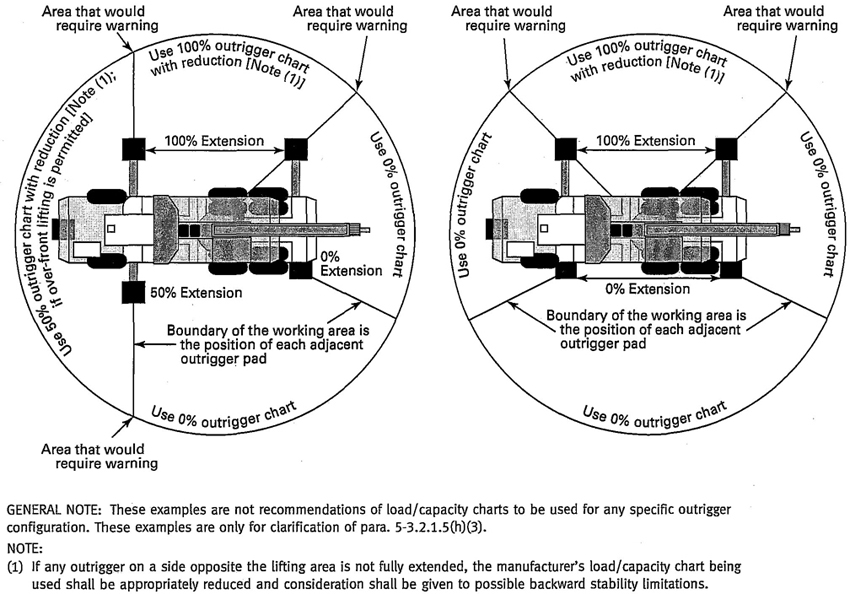
(04) Fig. 16 Examples of Typical Unequal Outrigger Extension Positions
(3) The empty hook shall be lashed or otherwise restrained so that it cannot swing freely.
(m) Before traveling a crane with a load, it shall be determined that this practice is not prohibited by the manufacturer. If not, a designated person shall be responsible for the operation. Decisions such as the necessity to reduce crane ratings, load position, boom location, ground support, travel route, and speed of movement shall be in accordance with that person′s determination. Specified tire pressure shall be maintained. The boom should be carried in line with the direction of travel. Sudden starts and stops should be avoided. Tag or restraint lines should be used to control swinging of the load.
(n) A crane with or without a load shall not be traveled with the boom so high that it may bounce back over the cab.
(o) When rotating the crane, sudden starts and stops shall be avoided. Rotational speed shall be such that the load does not swing out beyond the radius at which it can be controlled. A tag or restraint line shall be used when rotation of the load is hazardous.
(p) When a crane is to be operated with the boom at a fixed angle, the boom-hoist pawl or other positive holding device shall be engaged.
(q) Use of Winch Heads
(1) Fiber and wire rope shall not be handled on a winch head without the knowledge of the operator.
(2) While a winch head is being used, the operator shall be within convenient reach of the power unit control lever.
(r) Personnel shall not be permitted to ride the bare hook or a load of material suspended from the hook.
This volume recognizes that mobile and locomotive cranes are designed and intended for handling materials and not personnel. Personnel are only permitted to ride in a personnel platform supported by the crane load line attachment or boom-mounted platform when used in accordance with the requirements of ASME B30.23 and the crane manufacturer′s instructions. The crane shall not be used for other purposes while handling personnel. (Refer to ASME B30.23.)
32(a) Communication between the crane operator and the signal person shall be maintained continuously during all crane movements. If at any time communication is disrupted, the operator shall stop all crane movements until communication is restored and a proper signal is given and understood.
(b) If the operator has any concerns regarding the requested movement of the crane or needs to communicate with the signal person, the operator shall stop all crane movement. Crane movement shall not resume until the operator and the signal person agree the issue at hand has been resolved.
(c) If it is desired to give instructions to the operator, other than those provided by the established signal system, the crane movements shall be stopped.
Standard signals to the operator shall be in accordance with the standards prescribed in para. 5-3.3.4 or para. 5-3.3.5. Signals shall be discernible or audible at all times. No response shall be made unless signals are clearly understood.
Prior to signaling crane operations, all signal persons shall be tested by a designated person and demonstrate their qualifications in the following areas:
(a) basic understanding of crane operation and limitations
(b) standard hand signals described in para. 5-3.3.4 whenever hand signals are used
(c) standard voice signals described in para. 5-3.3.5 whenever voice signals are used
Hand signals shall be as shown in Fig. 17 and shall be posted conspicuously at the job site.
Prior to beginning lifting operations using voice signals, the signals shall be discussed and agreed upon by the person directing lifting operations, the crane operator, and the appointed signal person.
(a) Telephones, radios, or equivalent, if used, shall be tested before lifting operations begin. If the system is battery powered, extra batteries should be available at the job site.
(b) Prior to commencing a lift, the operator and signal person shall contact and identify each other.
(c) All directions given to the crane operator by the signal person shall be given from the operator′s direction perspective (e.g., swing right).
(d) Each series of voice signals shall contain three elements stated in the following order:
(1) function and direction
(2) distance and/or speed
(3) function stop
NOTE: These are some examples of signals.
(a) swing right 50 feet, 25 feet, 15 feet, 10 feet, 5 feet, 2 feet, swing stop
(b) load down 100 feet, 50 feet, 40 feet, 30 feet, … 2 feet, load stop
(c) load up slow, slow, slow, load stop
(e) For lifting operations using voice signals, the person directing lifting operations shall consider the complexity of the lift, the capabilities of the particular crane, the experience and skill of the operator and signal person, and the ability to communicate the necessary signals before permitting multiple simultaneous crane function signals.
For operations or crane attachments not covered by para. 5-3.3.4, para. 5-3.3.5, or para. 5-3.3.7, additions to or modifications of the standard signal procedures may be required. In all such cases, the required special signals shall be agreed upon in advance by the person directing lifting operations, the crane operator, and the signal person. These special signals should not be in conflict with the standard signals.
When moving the vehicle, the following signals shall be used:
(a) STOP: one short audible signal
(b) GO AHEAD: two short audible signals
(c) BACK UP: three short audible signals
Emergency signals can be given by anyone. The signal used shall be agreed upon for each job site location and it shall meet the requirements of para. 5-3.3.6 (e.g., multiple short audible signals or a continuous audible signal).
Rail clamps, if used, should have some slack between the point of attachment to the rail and the end fastened to the crane. Rail clamps shall not be used as a means of restraining tipping of a locomotive crane.
Cranes shall not be operated without the ballast or counterweight being in place as specified by the crane manufacturer. Under specific conditions, such as during crane assembly or unusual boom configurations, the crane manufacturer′s recommendations for the amount of ballast or counterweight shall be adhered to. The
33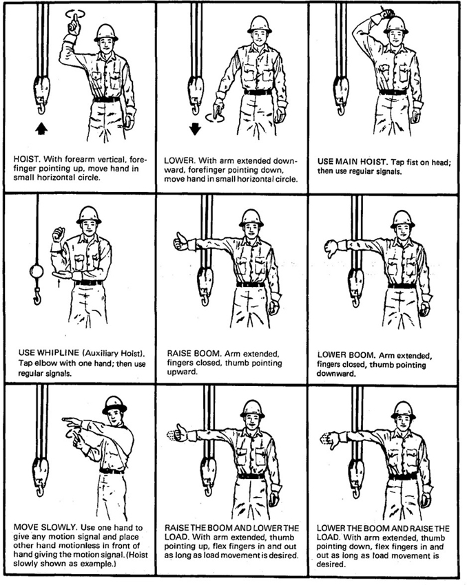
(04) Fig. 17 Standard Hand Signals for Controlling Crane Operations
34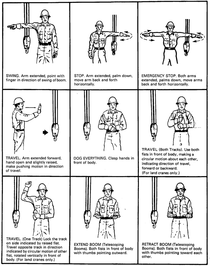
Fig. 17 Standard Hand Signals for Controlling Crane Operations (Cont’d)
35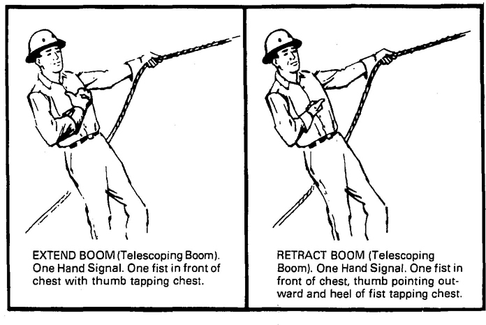
Fig. 17 Standard Hand Signals for Controlling Crane Operations (Cont’d)
maximum ballast or counterweight approved by the manufacturer for use on a given machine shall not be exceeded. Unauthorized addition of ballast or counter-weight constitutes a hazard in two ways.
(a) The structural competence of the various parts of the machine may be exceeded, causing failure.
(b) The manufacturer′s margin of backward stability may be exceeded and the crane may turn over backwards or damage various parts of the machine.
If a locomotive crane has been derailed, a wrecking frog or car replacer (or its equivalent) should be used and the crane should be hauled back onto the track by external power.
A locomotive crane shall not be swung into a position where railway cars on an adjacent track might strike it, until it has been ascertained that cars are not being moved on the adjacent track and that proper flag protection has been established.
5-3.4.5.1 General. This volume recognizes that operating mobile cranes where they can become electrified from electric power lines is an extremely hazardous practice. It is advisable to perform the work so there is no possibility of the crane, load line, or load becoming a conductive path. [See Fig. 18, sketches (a) and (b).] Cranes shall not be used to handle materials stored under electric power lines unless any combination of boom, load, load line, or machine component cannot enter the prohibited zone. Operating mobile cranes where they can become electrified with electric power lines is not recommended unless there is no less hazardous way to perform the job.
Any overhead wire shall be considered to be an energized line unless and until the person owning such line or the electrical utility authorities indicate that it is not an energized line. Crane operators shall not rely on the coverings of wires for their protection. Four conditions to consider when operating a mobile crane near electric power lines are the following:
(a) power lines de-energized and grounded as in para. 5-3.4.5.2
(b) power lines energized, crane operating less than the erected/fully extended boom length away as in para. 5-3.4.5.2 [see Fig. 18, sketch (c)]
(c) power lines energized, crane within prohibited zone as in para. 5-3.4.5.4
(d) crane in transit, no load, and boom lowered as in para. 5-3.4.5.5
5-3.4.5.2 Crane Operation Near De-energized and Grounded Electric Power Lines. This is the preferred condition under which the operation can be performed. The hazard of injury or death due to electrocution has been removed.
The following steps shall be taken to ensure de-energization of the power lines:
(a) The power company or owner of the power lines shall de-energize the lines.
(b) The lines shall be visibly grounded to avoid electrical feedback and appropriately marked at job site location.
36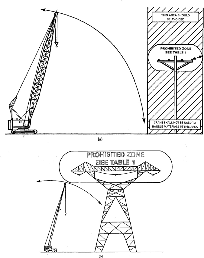
(04) Fig. 18 Danger Zone for Cranes and Lifted Loads Operating Near Electrical Transmission Lines
37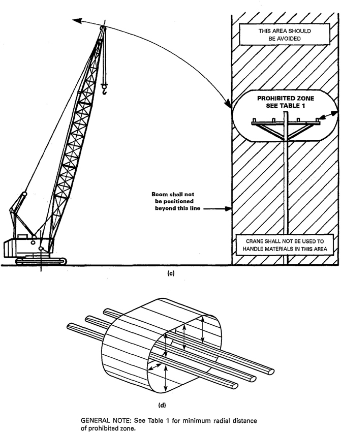
Fig. 18 Danger Zone for Cranes and Lifted Loads Operating Near Electrical Transmission Lines (Cont’d)
38| Normal Voltage, kV (Phase to Phase) |
Minimum Required Clearance, ft (m) [Note (1)] |
|---|---|
| Operation Near High-Voltage Power Lines | |
| to 50 | 10 (3.05) |
| Over 50 to 200 | 15 (4.60) |
| Over 200 to 350 | 20 (6.10) |
| Over 350 to 500 | 25 (7.62) |
| Over 500 to 750 | 35 (10.67) |
| Over 750 to 1,000 | 45 (13.72) |
| Operation in Transit With No Load and Boom or Mast Lowered | |
| to 0.75 | 4 (1.22) |
| Over 0.75 to 50 | 6 (1.83) |
| Over 50 to 345 | 10 (3.05) |
| Over 345 to 750 | 16 (4.87) |
| Over 750 to 1,000 | 20 (6.10) |
| NOTE: (1) Environmental conditions such as fog, smoke, or precipitation may require increased clearances. |
|
(c) A qualified representative of the owner of the lines or a designated representative of the electrical utility shall be on the side to verify that the steps of paras. 5-3.4.5.2(a) and (b) have been completed and that the lines are not energized.
(d) Durable signs shall be installed at the operator's station and on the outside of the crane warning that electrocution or serious bodily injury may occur unless minimum clearances, as specified in Table 2 [see Table 2 and Fig. 18, sketch (d)], are maintained between the crane or the load being handled and energized power lines.
(04) (e) If cage-type boom guards, insulating links, or proximity warning devices are used on cranes, such devices shall not be a substitute for the requirements of para. 5-3.4.5, even if such devices are required by law or regulation. In view of the complex, invisible, and lethal nature of the electrical hazard involved and to lessen the potential of false security, instructions on the electrical hazard involved, operating conditions for the devices, limitations of such devices, and testing requirements prescribed by the device manufacturer, if used, shall be understood by the crane operator, crew, and load-handling personnel. The required clearances to electrical lines, established in Table 2 of para. 5-3.4.5, shall be maintained, regardless of any devices used on the crane.
5-3.4.5.3 Crane Operation Within the Erected/Fully Extended Boom Length of the Prohibited Zone, With the Power Lines Energized. The following steps shall be taken to minimize the hazard of electrocution or serious injury as a result of contact between the energized power lines and the crane, load line, or load [see Fig. 18, sketch (c)].
(a) An on-site meeting between project management and a qualified representative of the owner of the lines or a designated representative of the electrical utility shall take place to establish the procedures to safely complete the operations.
(b) The specified clearance between the power lines and the crane, load line, and load shall be maintained at all times [see Table 2 and Fig. 18, sketch (d)].
(c) Load control, when required, shall use tag lines of a nonconductive type.
(d) A qualified signal person(s), whose sole responsibility is to verify that the required clearance is maintained, shall be in constant contact with the crane operator.
(e) No one shall be permitted to touch the crane or the load unless the signal person indicates it is safe to do so.
(f) Operation of boom and load over electric power lines is extremely dangerous, due to perception of distance and multiple contact points as viewed from the position of the operator and/or position of the signal person. The operator should avoid operating the crane, with or without a load in this area.
(g) The horizontal and vertical distance of movement of long span lines due to the wind shall be added to the minimum clearance distance as specified in Table 2 [see Table 2 and Fig. 18, sketch (d)]. A qualified representative of the owner of the lines or a designated representative of the electrical utility shall be consulted for specific distances.
(h) Devices such as ribbons or balls should be attached by a qualified person to the power lines to improve visibility, or equivalent means employed to aid in location of the prohibited zone.
(i) Durable signs shall be installed at the operator's station and on the outside of the crane warning that electrocution or serious bodily injury may occur unless minimum clearances, as specified in Table 2 [see Table 2 and Fig. 18, sketch (d)], are maintained between the crane or the load being handled and energized power lines.
(04) (j) If cage-type boom guards, insulating links, or proximity warning devices are used on cranes, such devices shall not be a substitute for the requirements of para. 5-3.4.5, even if such devices are required by law or regulation. In view of the complex, invisible, and lethal nature of the electrical hazard involved and to lessen the potential of false security, instructions on the electrical hazard involved, operating conditions for the devices, limitations of such devices, and testing requirements prescribed by the device manufacturer, if used, shall be understood by the crane operator, crew, and load-handling personnel. The required clearances to electrical
39lines, established in Table 2 of para. 5-3.4.5, shall be maintained, regardless of any devices used on the crane.
5-3.4.5.4 Crane Operation Within the Prohibited Zone With the Electric Power Lines Energized. Steps shall be taken to minimize the hazard of electrocution or serious injury as a result of contact between the energized power lines and the crane, load line, or load.
(a) Before such operations take place, a qualified person together with a qualified representative of the utility or an engineer qualified in power line transmission shall, after visiting the site, determine if this is the most feasible way to complete the operation and set minimum required clearances and procedures for such operations. These operations shall be under their supervision. The following may be required:
(1) crane/load grounded to line neutral by the utility.
(2) electrical system protective devices that automatically reenergize the circuit after a power line contact occurrence should be blocked or disengaged to inhibit this function.
(3) insulated barriers that are not a part of nor an attachment to the crane and will not allow contact between the energized electric power lines and the crane, load lines, or load.
(4) nonconductive barricades to restrict access to the crane work area.
(b) Load control, when required, shall use tag lines of a nonconductive type.
(c) A qualified signal person(s), whose sole responsibility is to verify that the clearances established in para. 5-3.4.5.4(a) are maintained, shall be in constant contact with the crane operator.
(d) The person(s) responsible for the operation shall alert and warn the crane operator and all persons working around or near the crane about the hazard of electrocution or serious injury and instruct them on how to avoid the hazard.
(e) All nonessential personnel shall be removed from the crane work area.
(f) No one shall be permitted to touch the crane or the load unless the signal person indicates it is safe to do so.
(04) (g) If cage-type boom guards, insulating links, or proximity warning devices are used on cranes, such devices shall not be a substitute for the requirements of para. 5-3.4.5, even if such devices are required by law of regulation. In view of the complex, invisible, and lethal nature of the electrical hazard involved and to lessen the potential of false security, instructions on the electrical hazard involved, operating conditions for the devices, limitations of such devices, and testing requirements prescribed by the device manufacturer, if used, shall be understood by the crane operator, crew, and load-handling personnel. The required clearances to electrical lines, established in Table 2 of para. 5-3.4.5, shall be maintained, regardless of any devices used on the crane.
5-3.4.5.5 Operations in Transit With No Load and Boom Lowered
(a) While in transit with no load and boom and boom support system lowered, the clearance shall be as specified in Table 2 [see Table 2 and Fig. 18, sketch (d)].
(b) When planning transit of the crane, the effect of speed and terrain on boom and crane movement shall be considered.
Firm footing under both crawler tracks, all tires, or individual outrigger pads should be level within 1%. Where such a footing is not otherwise supplied, it should be provided by timbers, cribbing, or other structural members to distribute the load so as not to exceed the allowable bearing capacity of the underlying material.
(a) Necessary clothing and personal belongings shall be stored in such a manner as to not interfere with access or operation.
(b) Tools, oil cans, waste, and other necessary articles shall be stored in the toolbox, and shall not be permitted to lie loose in or about the cab.
(a) When refueling with gasoline using a portable container, it shall be a safety-type can equipped with an automatic closing cap and a flame arrester.
(b) Machines shall not be refueled while the engine is running.
(c) Smoking or open flames shall be prohibited in the refueling area.
(a) A portable fire extinguisher, with a basic minimum extinguishers rating of 10 BC, shall be installed in the cab or at the machinery housing.
(b) Operating and maintenance personnel shall be familiar with the use and care of the fire extinguishers provided.
40FOREWORD
This publication includes all of the written replies issued between the indicated dates by the Secretary, speaking for the ASME B30 Committee, Safety Standards for Cableways, Cranes, Derricks, Hoists, Hooks, Jacks, and Slings, to inquiries concerning interpretations to technical apsects of ASME B30.5, Mobile and Locomotive Cranes.
These replies are taken verbatim from the original letters, except for any typographical corrections and some minor editorial corrections made for the purpose of improved clarity.
These interpretations were prepared in accordance with the accredited ASME procedures. ASME procedures provide for reconsideration of these interpretations when or if additional information is available which the inquirer believes might affect the interpretation. Further, persons aggrieved by this interpretation may appeal to the cognizant ASME Committee or Subcommittee. ASME does not “approve,” “certify,” “rate,” or “endorse” any item, construction, proprietary device, or activity.
I-1Interpretation: 5-71
Subject: ASME B30.5-1994, para. 5-2.4.3(b)(5)
Date Issued: January 28, 2002
Question: Does para. 5-2.4.3(b)(5), pertaining to “evidence of heat damage from any cause” apply to the end of the rope after it passes through the wedge socket (as in flame cutting and welding)?
Reply: No.
Interpretation: 5-72
Subject: ASME B30.5-2000 and B30.5a-2002, New and Existing Installations
Date Issued: November 1, 2002
Question: Would a crane that was manufactured prior to the effective date (March 29, 2003) without meeting the provisions of para. 5-1.9.9.2 and purchased or operated after the effective date be in compliance with ASME B30.5a-2002?
Reply: Yes.
Interpretation: 5-73
Subject: ASME B30.5-2000, para. 5-3.1.2, Qualification of Operators
Date Issued: January 31, 2003
Question: Does B30.5 prohibit a person with monocular vision from operating a crane?
Reply: Paragraph 5-3.1.2(a) includes the phrase, “unless it can be shown that failure to meet the qualification will not affect the operation of the crane.” Hence, if it can be demonstrated that an individual can safely operate a crane, then this requirement of the volume has been satisfied.
Interpretation: 5-74
Subject: ASME B30.5-2000, para. 5-1.2.1, Backward Stability
Date Issued: January 31, 2003
Question (1): Would a crane that loses its load, unexpectedly coming unloaded, still be required to have the proper backward stability in accordance with para. 5-1.2.1?
Reply (1): The backward stability conditions only apply prior to a load being lifted.
Question (2): Is a crane losing its load beyond the constraints of this volume?
Reply (2): Yes.
Interpretation: 5-75
Subject: ASME B30.5-2000, para. 5-3.1.2(b)(3); Reconsideration of ASME B30 Interpretation 5-61
Date Issued: September 12, 2003
The B30 Committee reaffirms Interpretation 5-61.
I-2 I-3 I-4 I-5ASME B30.5-2004