
In order to promote public education and public safety, equal justice for all, a better informed citizenry, the rule of law, world trade and world peace, this legal document is hereby made available on a noncommercial basis, as it is the right of all humans to know and speak the laws that govern them.
ANSI Z90.4-1984
C-78-11
American National Standard
for Protective Headgear – for Bicyclists
ANSI®
Z90.4-1984
Secretariat
Snell Memorial Foundation, Inc
Approved March 12, 1984
American National Standards Institute, Inc
American National Standard
Approval of an American National Standard requlres verification by ANSI that the requirements for due process, consensus, and other criteria for approval have been met by the standards developer.
Consensus is established when, in the judgment of the ANSI Board of Standards Review, substantial agreement has been reached by directly and materially affected interests. Substantial agreement means much more than a simple majority, but not necessarily unanimity. Consensus requires that all views and objections be considered, and that a concerted effort be made toward their resolution.
The use of American National Standards is completely voluntary; their existence does not in any respect preclude anyone, whether he has approved the standards or not, from manufacturing, marketing, purchasing, or using products, processes, or procedures not conforming to the standards.
The American National Standards Institute does not develop standards and will in no circumstances give an interpretation of any American National Standard. Moreover, no person shall have the right or authority to issue an interpretation of an American National Standard, in the name of the American National Standards Institute. Requests for interpretations should be addressed to the secretariat or sponsor whose name appears on the title page of this standard.
CAUTION NOTICE: This American National Standard may be revised or withdrawn at any time. The procedures of the American National Standards Institute require that action be taken to reaffirm, revise, or withdraw this standard no later than five years from the date of approval. Purchasers of American National Standard may receive current information on all standards by calling or writing the American National Standards Institute.
Published by
American National Standards Institute
1430 Broadway, New York, New York 10018
Copyright © 1984 by American National Standards Institute, Inc
All rights reserved.
No part of this publication may be reproduced in any form, in an electronic retrieval system or otherwise, without the prior written permission of the publisher.
Printed in the United States of America
A1M984/7
3(This Foreword is not part of American National Standard Z90.4-1984.)
On December 9, 1960, the Sports Car Club of America requested that the American Standards Association (now American National Standards Institute, Inc) initiate a project to prepare specifications for road users’ helmets. A general conference was held at the ASA headquarters in April 1961 that was attended by representatives from various consumer groups, helmet manufacturers, testing organizations, and branches of the military service including both Army and Navy. The Safety Standards Board established American National Standards Committee Z90 and charged it with the responsibility for establishing a safety code for vehicular head protection. The scope of the committee is to establish safety requirements for head protection for automobile drivers engaged in high hazard activities or occupations and for motorcyclists.
Following nearly five years of deliberations by the committee, its resulting proposals were approved by the Safety Standards Board on June 22, 1966. Subsequent experience with the specifications as originally adopted indicated a need for certain clarification and simplification. The specifications have been revised three times to incorporate the modifications deemed appropriate by the committee. The committee considered other hazardous activities and as a consequence developed this standard for recreational bicycle riders.
CAUTION: It is essential that any specific complete standard be applied or utilized only within the scope of its intended application, because there exists a great number of types of protective headgear with widely varying uses. The resulting differences in design requirements may result in very necessary compromise involving factors that include comfort, weight, visual, and auditory requirements as well as degree and extent of protection.
Suggestions for improvement of this standard will be welcome. They should be sent to the Snell Memorial Foundation, P.O. Box 733, Wakefield, RI 02880.
This standard was processed and approved for submittal to ANSI by American National Standards Committee on Vehicular Head Protection, Z90. Committee approval of the standard does not necessarily imply that all committee members voted for its approval. At the time it approved this standard the Z90 Committee had the following members:
George G. Snively,* Chairman
| Organization Represented | Name of Representative |
|---|---|
| American Association for Automotive Medicine | George G. Snively* |
| American Medical Association | H.A. Fenner, Jr |
| American Power Boat Association | John Langley |
| American Sports Company | Victor J. Padilla |
| Ballen Helmet Company | Harold Bailen |
| Bell Helmets, Inc | Dean Fisher |
| California Association of Bicycling Organizations | Alan Wachtel |
| California Highway Patrol | Hal Eldridge |
| Hanna-Pro Enterprises | Harold Stock |
| Mountain Safety Research | Ted McCoy |
| National Bureau of Standards | Nick Calvano |
| Safety Helmet Council of America | Ivan J. Wagar |
| Skid-Lid Manufacturing Company | R. Kevin Montgomery |
| Snell Memorial Foundation, Inc | C. O. Chichester† |
| Sports Car Club of America | George G. Snively* |
| U.S. Air Force Logistics Command | William C. Chilcott |
| U.S. Army, Aeromedical | Joseph Haley |
| U.S. Army, Quartermaster Research Command | Bruce Buckland |
| U.S. Naval Aviation | Channing L. Ewing |
| Washington Area Bicycle Association | Randolph Swart |
| *Deceased. †Present Chairman. |
|
| Independent Experts | |
|---|---|
| George R. Henderson | A.L. Lastnik |
| Harry Hurt | James H. McElhaney |
| A. Marshall Irving | Verne Roberts |
| Arthur James | |
| SECTION | PAGE | |
|---|---|---|
| 1. | Scope, Purpose, and Requirements | 7 |
| 1.1 Scope | 7 | |
| 1.2 Purpose | 7 | |
| 1.3 Requirements | 7 | |
| 2. | Referenced Standards | 7 |
| 3. | Definitions | 7 |
| 4. | Construction | 10 |
| 4.1 General | 10 | |
| 4.2 Projections | 10 | |
| 5. | Materials | 10 |
| 6. | Marking | 11 |
| 7. | Samples for Testing | 11 |
| 7.1 Condition and Attachments | 11 | |
| 7.2 Number of Samples | 11 | |
| 8. | Test Schedule | 11 |
| 9. | Conditioning Environments | 11 |
| 9.1 Ambient Conditions | 11 | |
| 9.2 Low Temperature | 11 | |
| 9.3 High Temperature | 11 | |
| 9.4 Water Immersion | 11 | |
| 10. | Extent of Protection | 11 |
| 11. | Peripheral Vision | 11 |
| 12. | Tests of Impact Energy Attenuation | 12 |
| 12.1 Measurement of Impact Energy Attenuation | 12 | |
| 12.2 Acceptable Acceleration Levels | 12 | |
| 12.3 Impact Sites | 12 | |
| 13. | Test of Retention System Strength | 12 |
| 13.1 Dynamic Test Description | 12 | |
| 13.2 Apparatus | 12 | |
| 13.3 Procedure | 12 | |
| 13.4 Interpretation of Results | 12 | |
| 14. | Requirements for Test Equipment | 12 |
| 14.1 Equipment and Environment | 12 | |
| 14.2 Instrumentation Check | 15 | |
| 14.3 Velocity-Sensing System | 15 | |
| 15. | Reference Marking | 15 |
| 16. | Records of Tests | 15 |
| 17. | Test Headforms | 15 |
| 17.1 General | 15 | |
| 17.2 Material of Headforms | 15 | |
| 17.3 Mass of Headforms | 15 | |
| Tables | ||
| Table 1 Polar Coordinates of Horizontal Half-Sections | 8 | |
| Table 2 Reference Marking Dimensions | 13 5 | |
| Figures | ||
| Figure 1 Typical Headform | 7 | |
| Figure 2 Extent of Protection and Clearance for Goggles | 9 | |
| Figure 3 Headform Elevation | 9 | |
| Figure 4 Horizontal Half-Sections at Datum Levels | 10 | |
| Figure 5 Apparatus for Tests for Impact Energy Attenuation | 13 | |
| Figure 6 Apparatus for Test for Retention System Strength | 14 | |
American National Standard for Protective Headgear - for Bicyclists
1.1 Scope. This standard specifies minimum performance criteria and describes test methods for protective headgear for wear by bicyclists.
1.2 Purpose. The purpose of this standard is to provide bicyclists with minimum acceptable levels of head protection, acknowledging the desirability of light weight and ventilation.
1.3 Requirements. Tests of the protective-headgear assembly shall be conducted to ensure compliance, under specific environmental conditions, with the requirements in this standard for:
(1) Impact attenuation properties of the protective headgear
(2) Adequacy of the strength of the retention system
This standard is intended for use in conjunction with the following standards:
ISO/DIS 6220-1983, Headforms for Use in the Testing of Protective Helmets1
SAE J211-JUN80, Instrumentation for Impact Tests2
3.1 Basic Plane. A plane at the level of the external auditory meatus (external ear opening) and the inferior margin of the orbit (lower edge of the eye socket). (See Figure 1.)
3.2 Midsagittal Plane. A longitudinal plane passing through the vertex of the headform, perpendicular to
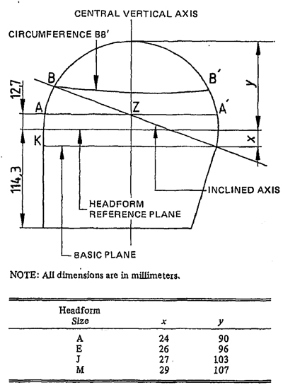
Figure 1
Typical Headform
the basic plane, that geometrically bisects the headform. (See Figure 2.)
3.3 Reference Plane. A plane at a given distance above and parallel to the basic plane. (See Figure 1.)
3.4 Reference Headform. A measuring device contoured to the dimensions of one of the four headforms described in Figures 3 and 4, with surface markings indicating the locations of the basic, midsagittal, and reference planes and the centers of the external ear openings.
1Available from American National Standards Institute, 1430 Broadway, New York, NY 10018.
2Available from the Society of Automotive Engineers, 400 Commonwealth Drive, Warrendale, PA 15096.
7| Headform Size A: Dimension y = 90 mm | |||||||||||||
|---|---|---|---|---|---|---|---|---|---|---|---|---|---|
| Height above reference plane |
0° Front |
15° | 30° | 45° | 60° | 75° | 90° | 105° | 120° | 135° | 150° | 165° | 180° Back |
| 0 | 88,0 | 86,5 | 83,0 | 75,5 | 70,0 | 67,0 | 66,5 | 69,5 | 73,5 | 78,5 | 84,0 | 87,0 | 88,0 |
| 20 | 85,5 | 84,5 | 82,5 | 75,5 | 70,0 | 67,0 | 66,5 | 69,5 | 73,5 | 78,5 | 84,0 | 87,0 | 87,0 |
| 40 | 80,0 | 79,5 | 79,0 | 72,0 | 67,5 | 65,0 | 64,5 | 67,0 | 71,0 | 76,0 | 80,5 | 82,0 | 81,5 |
| 50 | 75,0 | 75,0 | 74,5 | 68,5 | 63,5 | 61,0 | 60,5 | 63,5 | 67,0 | 72,0 | 76,0 | 77,0 | 77,0 |
| 60 | 68,0 | 68,0 | 67,5 | 62,5 | 57,5 | 66,5 | 55,0 | 68,0 | 61,6 | 66,0 | 70,0 | 70,0 | 70,5 |
| 70 | 56,0 | 56,0 | 56,5 | 53,0 | 49,5 | 47,0 | 47,0 | 49,0 | 53,0 | 57,0 | 61,5 | 61,0 | 61,0 |
| 80 | 37,0 | 37,5 | 37,0 | 36,5 | 35,5 | 34,0 | 34,0 | 36,0 | 39,5 | 44,5 | 49,0 | 49,0 | 48,5 |
| 85 | 23,0 | 24,0 | 23,0 | 22,0 | 22,0 | 23,0 | 24,0 | 24,5 | 29,5 | 33,5 | 36,0 | 36,5 | 37,0 |
| Headform Size E: Dimension y = 96 mm | |||||||||||||
|---|---|---|---|---|---|---|---|---|---|---|---|---|---|
| Height above reference plane |
0° Front |
15° | 30° | 45° | 60° | 75° | 90° | 105° | 120° | 135° | 150° | 165° | 180° Back |
| 0 | 94,5 | 93,0 | 90,0 | 82,0 | 76,5 | 73,5 | 73,0 | 76,0 | 80,0 | 85,0 | 91,0 | 94,0 | 94,5 |
| 20 | 92,5 | 91,5 | 89,0 | 82,0 | 76,5 | 73,6 | 73,0 | 76,0 | 80,0 | 85,0 | 90,5 | 93,5 | 94,0 |
| 40 | 87,0 | 87,5 | 85,0 | 79,5 | 74,5 | 71,0 | 71,5 | 74,0 | 77,5 | 82,5 | 88,0 | 89,0 | 89,0 |
| 50 | 82,5 | 83,0 | 81,0 | 76,0 | 71,0 | 68,0 | 68,0 | 70,5 | 74,0 | 79,5 | 83,5 | 84,5 | 84,5 |
| 60 | 76,5 | 76,5 | 76,5 | 71,0 | 66,5 | 63,5 | 63,5 | 66,0 | 69,5 | 74,0 | 78,5 | 79,0 | 79,0 |
| 70 | 66,5 | 66,5 | 66,5 | 63,0 | 59,0 | 68,5 | 56,5 | 58,5 | 62,0 | 66,5 | 70,5 | 71,0 | 71,0 |
| 80 | 52,0 | 52,0 | 52,0 | 50,0 | 47,5 | 46,0 | 46,5 | 48,0 | 61,0 | 56,0 | 59,6 | 60,0 | 60,0 |
| 85 | 41,5 | 41,5 | 41,5 | 40,5 | 39,5 | 39,0 | 39,5 | 41,0 | 44,0 | 48,0 | 61,5 | 52,0 | 52,0 |
| 90 | 28,0 | 28,0 | 28,5 | 28,5 | 28,6 | 29,0 | 30,0 | 31,0 | 34,0 | 37,5 | 41,5 | 42,0 | 42,0 |
| 95 | 10,0 | 10,0 | 10,0 | 10,0 | 10,0 | 10,5 | 11,0 | 12,0 | 13,5 | 15,0 | 16,0 | 16,0 | 16,0 |
| Headform Size J: Dimension y=103 mm | |||||||||||||
|---|---|---|---|---|---|---|---|---|---|---|---|---|---|
| Height above reference plane |
0° Front |
15° | 30° | 45° | 60° | 75° | 90° | 105° | 120° | 135° | 150° | 165° | 180° Back |
| 0 | 101,0 | 99,5 | 95,5 | 87,5 | 82,5 | 79,5 | 79,5 | 82,0 | 86,0 | 92,0 | 97,0 | 100,5 | 101,0 |
| 20 | 99,0 | 97,0 | 93,5 | 87,6 | 82,0 | 79,5 | 79,5 | 82,0 | 86,0 | 92,0 | 96,5 | 99,5 | 100,0 |
| 40 | 93,0 | 92,5 | 90,0 | 85,5 | 80,0 | 77,5 | 77,5 | 80,6 | 84,0 | 89,0 | 93,0 | 95,5 | 95,5 |
| 50 | 90,0 | 89,0 | 87,0 | 83,0 | 77,0 | 74,5 | 75,0 | 77,5 | 81,0 | 86,0 | 90,0 | 91,5 | 91,5 |
| 60 | 84,0 | 83,0 | 81,5 | 77,0 | 73,0 | 70,0 | 71,0 | 73,0 | 77,0 | 81,0 | 85,6 | 87,0 | 87,0 |
| 70 | 76,0 | 75,5 | 74,0 | 71,0 | 67,0 | 65,0 | 65,6 | 67,0 | 71,5 | 75,0 | 79,0 | 80,0 | 80,0 |
| 80 | 65,0 | 65,0 | 64,0 | 61,0 | 58,5 | 56,0 | 57,0 | 59,0 | 62,5 | 66,5 | 69,5 | 71,0 | 71,0 |
| 85 | 58,0 | 58,0 | 56,5 | 54,5 | 52,0 | 50,0 | 51,0 | 52,5 | 56,6 | 60,5 | 64,5 | 65,0 | 65,0 |
| 90 | 48,5 | 48,0 | 47,0 | 45,5 | 43,5 | 43,0 | 44,0 | 46,0 | 49,5 | 54,0 | 57,0 | 58,5 | 58,5 |
| 95 | 37,0 | 36,5 | 35,0 | 34,0 | 33,0 | 33,5 | 34,5 | 36,0 | 39,0 | 43,0 | 46,5 | 47,0 | 47,0 |
| 100 | 20,0 | 20,0 | 19,5 | 19,0 | 18,5 | 18,5 | 19,0 | 20,5 | 23,5 | 27,5 | 31,0 | 31,5 | 31,0 |
| Headform Size M: Dimension y = 107 mm | |||||||||||||
|---|---|---|---|---|---|---|---|---|---|---|---|---|---|
| Height above reference plane |
0° Front |
15° | 30° | 45° | 60° | 75° | 90° | 105° | 120° | 135° | 150° | 165° | 180° Back |
| 0 | 106,0 | 104,0 | 101,0 | 93,5 | 87,0 | 84,5 | 84,0 | 86,5 | 91,0 | 96,0 | 102,0 | 106,0 | 106,0 |
| 20 | 103,5 | 102,5 | 99,5 | 93,0 | 87,0 | 84,5 | 84,0 | 88,5 | 91,0 | 96,0 | 101,5 | 105,5 | 105,5 |
| 40 | 99,0 | 98,5 | 96,5 | 90,5 | 86,0 | 82,6 | 82,0 | 84,0 | 88,5 | 93,5 | 96,0 | 100,5 | 100,5 |
| 50 | 95,5 | 94,5 | 93,0 | 87,5 | 82,0 | 79,6 | 79,0 | 81,5 | 85,5 | 90,0 | 93,0 | 97,0 | 97,0 |
| 60 | 89,5 | 89,6 | 88,0 | 83,0 | 77,5 | 76,0 | 75,0 | 77,0 | 81,6 | 86,5 | 91,0 | 92,0 | 92,0 |
| 70 | 82,0 | 82,0 | 81,0 | 77,0 | 72,0 | 69,5 | 69,5 | 71,5 | 75,5 | 81,0 | 84,0 | 85,5 | 85,5 |
| 80 | 71,5 | 71,5 | 71,0 | 68,0 | 64,0 | 61,5 | 61,5 | 64,0 | 67,0 | 72,0 | 76,0 | 77,0 | 77,0 |
| 85 | 64,5 | 64,5 | 64,0 | 61,5 | 59,0 | 57,0 | 67,0 | 58,5 | 61,5 | 66,5 | 71,0 | 72,0 | 72,0 |
| 90 | 56,5 | 56,5 | 56,5 | 55,0 | 53,0 | 51,5 | 51,5 | 53,0 | 56,0 | 60,5 | 64,5 | 66,0 | 66,0 |
| 95 | 46,5 | 46,5 | 47,0 | 46,5 | 45,5 | 44,0 | 44,0 | 45,5 | 48,5 | 63,0 | 57,5 | 59,0 | 58,5 |
| 100 | 32,0 | 32,0 | 32,5 | 33,0 | 34,0 | 34,0 | 34,5 | 35,5 | 38,5 | 43,0 | 46,5 | 48,5 | 48,0 |
| 106 | 12,0 | 12,0 | 13,0 | 14,0 | 16,0 | 16,0 | 17,6 | 19,5 | 21,0 | 25,0 | 29,5 | 30,0 | 30,0 |
| NOTE: All dimensions are in millimeters. | |||||||||||||
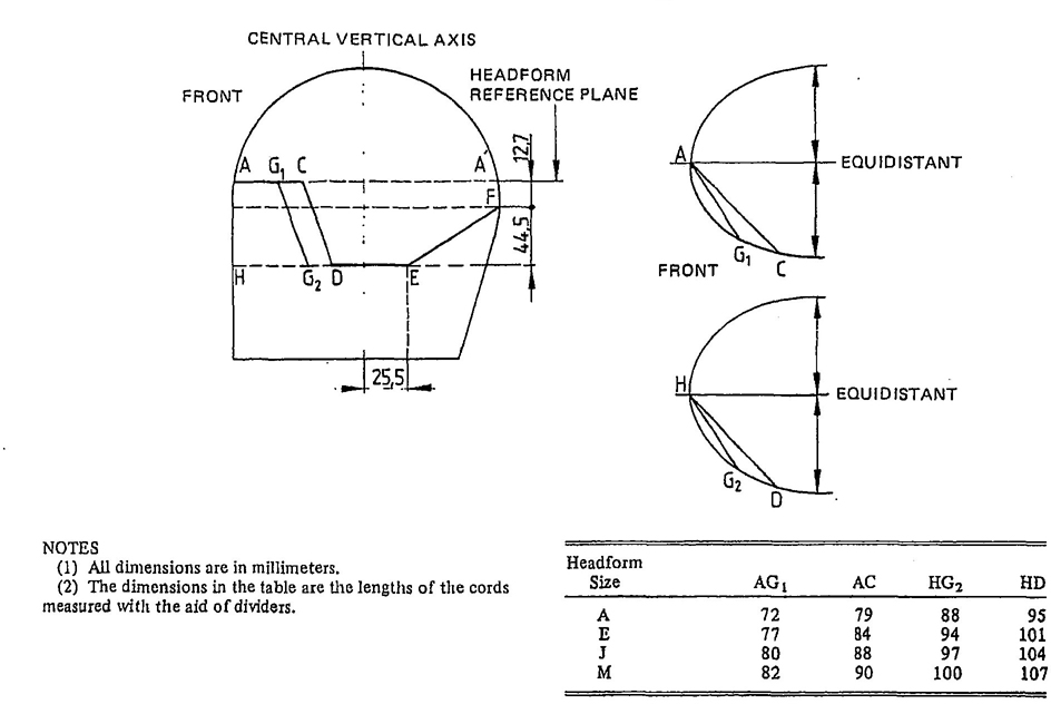
Figure 2
Extent of Protection and Clearance for Goggles
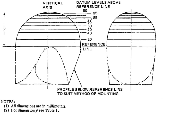
Figure 3
Headform Elevation
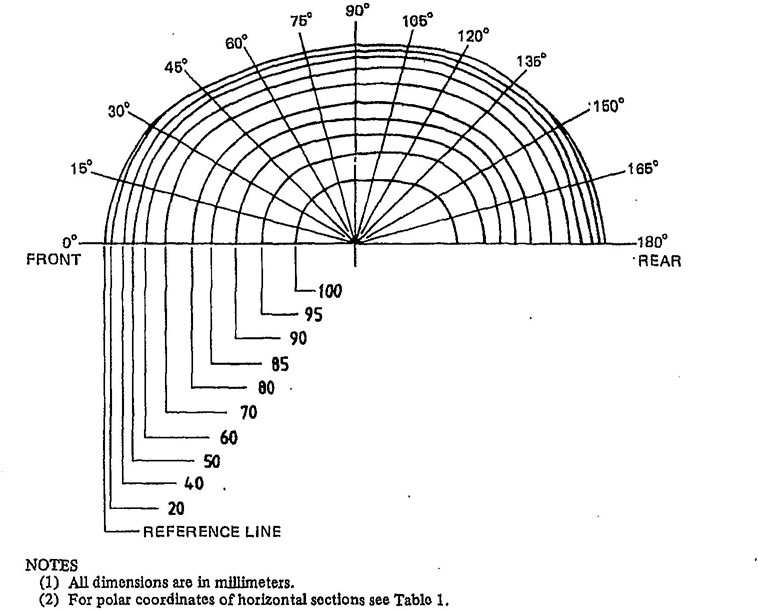
Figure 4
Horizontal Half-Sections at Datum Levels
3.5 Test Headform. A test device contoured to the dimensions of the four headforms described in Figures 3 and 4 and Table 1 for all surface areas that contact the helmet, with surface markings indicating the locations of the basic, midsagittal, and reference planes, Headforms shall be as defined in ISO/DIS 6220-1983.
3.6 Retention System. The complete assembly that maintains the protective headgear in a stabilized position on the wearer′s head.
3.7 Projection. Any part of the protective headgear, internally or externally, that juts out or extends beyond the surface in an abrupt fashion.
3.8 Positioning Index. The distance from the lowest point of the brow at the lateral midpoint of the helmet to the basic plane of a reference headform at which the helmet is considered firmly and properly positioned on the reference headform.
3.9 Bicyclist. A bicyclist is a person operating a people-powered surface vehicle with one or more wheels.
3.10 Shell. The outer surface of the protective device.
4.1 General. The helmet shall be constructed to absorb impact energy and to provide a retention system.
4.2 Projections. There shall be no permanent external projections greater than 5 mm above the outer surface of the shell. Rivet heads shall be radiused and shall not project more than 2 mm above the outer surface of the shell. There shall be no inward-facing sharp edges on the inside of the helmet. Rigid internal projections shall be covered with padding.
The characteristics of the materials used in the manufacture of helmets shall not undergo appreciable alteration due to aging or normal use, such as exposure to sun, extremes of temperature, and rain.
If hydrocarbons, cleaning fluids, paints, or transfers and other additions will affect the helmet adversely, a warning shall be provided.
10The materials used for those parts of the helmet coming into contact with the skin shall not undergo appreciable alteration because of sweat or of toiletries. Materials that cause skin disorders shall not be used.
Bicyclist′ headgear offered for sale shall have permanent and legible marking that will give traceability, identification of the manufacturer, date of manufacture, and size. The headgear shall be labeled with the following instructions:
(1) “This helmet is designed only for bicycle use.”
(2) “No helmet can protect the wearer against all for seeable impacts. However, for maximum protection, the helmet must be of good fit and all retention straps must be securely fastened.”
(3) “This helmet is so constructed that the energy of an impact may be absorbed through partial destruction of the headgear, though damage may not be visible to the naked eye. If it suffers such an impact, it should either be returned to the manufacturer for competent inspection or destroyed and replaced”
(4) “This helmet can be seriously damaged by some common substances without visible damage. Apply only the following: (Recommended cleaning agents, paints, adhesives, and the like) as appropriate.”
7.1 Condition and Attachments. For all testing, protective headgear shall be tested in the condition as offered for sale. Attachments shall not be installed on the helmet during testing.
7.2 Number of Samples. Four samples for each available headform size are required for testing. Each test sample, following exposure to the environmental condition specific to it (described in Section 9) shall be subjected to the tests described in Section 8.
For each set of four samples:
(1) Each helmet shall be examined for extent of protection (see Section 10) and peripheral vision (see Section 11).
(2) Each helmet shall be conditioned to one of the environments specified in 9.1, 9.2, 9.3, or 9.4 as required by the test sequence for impact energy attenuation given in 12.3.1.
(3) Each helmet shall be subjected to the tests for impact energy attenuation and retention system strength us described in Sections 12 and 13, respectively.
Testing shall begin immediately after removal from the conditioning equipment. The maximum time during which the protective headgear may be out of the conditioning environment shall not exceed 5 minutes. The helmet shall then be returned to the conditioning environment for a minimum of 15 minutes before again being withdrawn. This process shall be continued until a specific item has been put through all necessary testing.
9.1 Ambient Conditions. The first protective headgear shall be conditioned in the environment defined in 14.1 for a period of not less than 4 hours.
9.2 Low Temperature. The second protective headgear shall be conditioned by being exposed to a temperature of - 10°C ± 2°C for not less than 4 hours in a controlled environmental temperature apparatus.
9.3 High Temperature. The third protective headgear shall be conditoned by being exposed to an air temperature of 50° ±2°C for a period of not less than 4 hours in a circulating air oven.
9.4 Water Immersion. The fourth protective headgear shall be immersed in water at a temperature of 18°C to 27°C for a period of not less than 4 hours.
The entire area of the headgear above the test line stipulated in 15.1 shall attenuate impact energy to the minimum requirements specified in 12.2 and 12.3.
The helmet shall provide peripheral vision clearance of a minimum of 105 degrees horizontally to each side of the midsagittal plane through the point K (see Figure 1). This angle shall be measured while the helmet is mounted on the smallest headform appropriate to the size range of the helmet.
1112.1 Measurement of Impact Energy Attenuation. Impact energy attenuation shall be measured by determining imparted acceleration to an appropriately instrumented standard test headform specified in Section 17. The subject protective headgear shall be placed on the headform and the assembly shall be dropped in a guided fall, vertical within 13 mm per 5.0 meters of height, onto a steel anvil fixed on a rigid base. (see Figure 5.)
12.2 Acceptable Accleration Levels. The peak acceleration, as measured by the instrumented test headform, resulting from the impacts delivered to each of the four preconditioned protective headgear, shall not exceed 300 units of gravity ((G′)s)
12.3 Impact Sites
12.3.1 Each helmet shall be impacted once at each of four sites onto a flat steel anvil and a hemispherical steel anvil as specified in 12.3.5 and 12.3.6. The impact sites shall be placed at any point on the area above the test line described in 15.1 and separated by a distance not less than one-fifth of the maximum circumference of the helmet. If there are mechanical fasteners in the test area, at least one shall be impacted. At least one impact shall be 12 mm above the test line at the front, rear, or side of helmet. In each test series, impacts shall be equally divided between flat and hemispherical anvils.
12.3.2 The heights of the guided-free-fall drop for the helmet and test headform combination onto the hemispherical anvil and flat anvil shall be at least 1.0 meter and achieve an impact velocity of 4.57 m/s + 0%, −5%.
12.3.3 The weight of the drop assembly, as specified in Table 2, shall be the combined weight of the instrumented test headform and supporting assembly for the drop test. The weight of the supporting assembly shall not exceed 25% of the weight of the drop assembly. The center of gravity of the combined test headform and supporting assembly shall lie within a cone having its axis vertical and forming a 10° included angle with the vertex as the point of impact.
12.3.4 The acceleration transducer shall be mounted at the center of gravity of the combined test headform and supporting assembly with the sensitive axis aligned to within 5° of the vertical when the test headform is in the impact position. The acceleration data channel shall comply with the requirements in SAE J211-JUN80 for channel Class 1000.
12.3.5 The flat anvil shall be constructed of steel with an impact face having a minimum diameter of 125 mm. The hermispherical anvil shall be constructed of steel with an impact face having a radius of 50 mm.
12.3.6 The rigid mount for both of the anvils shall consist of a solid mass of at least 135 kg, the upper surface of which shall consist of a steel plate with a minimum thickness of 25 mm and minimum surface area of 0.3 m2.
12.3.7 Impact velocity shall be measured during each test and shall be within the limits specified in 12.3.2. This measurement shall correlate with pretest and posttest G calibration of the drop system as specified in 13.1.1.
13.1 Dynamic Test Description. The dynamic test of the retention system shall be conducted by delivering a 19.6 J impact to the retention system by dropping a mass of 2 kg a distance of 1 meter. (See Figure 6 for a typical test apparatus.)
13.2 Apparatus. The test apparatus shall provide for a 1-meter drop of a cylindrical mass that has, along its axis, a hole of sufficient diameter to allow it to fit around a steel rod that is square or circular with a diameter of 12 to 15 mm. The rod shall have a steel end stop and a minimum length of 1 meter plus the height of the cylinder. The mass of the entire loading apparatus excluding the 2-kg cylindrical mass shall be 1.5 kg ± 0.1 kg.
13.3 Procedure. The helmet shall be placed on the headform. The retention system shall be secured through rollers so that the entire dynamic test apparatus hangs freely on this retention system. The strap of the retention system shall be fastened under a stirrup that approximately conforms to the shape of the bone structure of the lower jaw. This stirrup shall consist of two metal rollers each with a diameter of 12.5 mm + 0.5 mm that have a center separation of 76.0 mm ± 0.5 mm. Then the 2-kg mass shall be raised 1 meter and allowed to fall freely against the rigid end stop.
13.4 Interpretation of Results.
When tested the retention system shall not fail. The system shall remain intact so that the loading device does not become detached from the retention system. Maximum elongation of the retention system shall not exceed 25 mm.
14.1 Equipment and Environment. Prior to testing, all equipment shall be turned on and allowed to warm up for at least 30 minutes or until equilibrium is reached, whichever time is greater.
12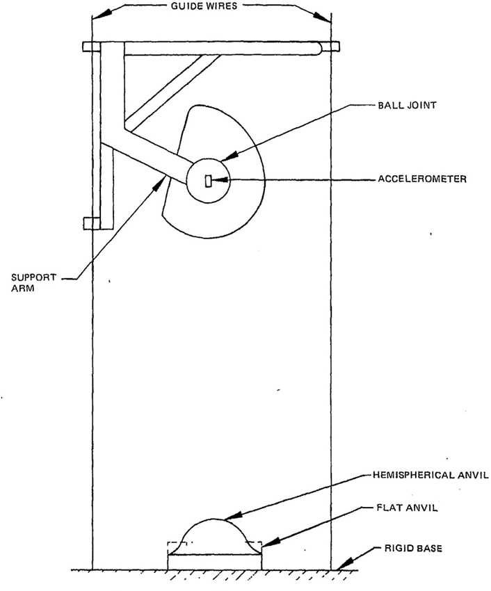
Figure 5
Apparatus for Tests for Impact Energy Attenuation
| Headform Size |
h | a | i | b | j |
|---|---|---|---|---|---|
| A | 55 | 29.3 | 30 | 29.3 | 5 |
| E | 55 | 31.5 | 30 | 31.5 | 5 |
| J | 58 | 33.7 | 33 | 33.7 | 8 |
| M | 60 | 35.3 | 35 | 35.3 | 10 |
| NOTE: All dimensions are in millimeters. | |||||
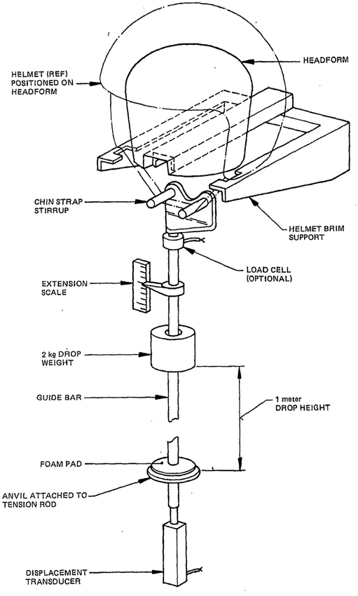
Figure 6
Apparatus for Test for Retention System Strength
The following environmental conditions shall be maintained throughout the period of calibration and testing:
Relative humidity: 20%-80%
Temperature: 18°C-27°C
14.2 Instrumentation Check. The entire instrumentation system shall be checked before and after each series of tests by impacting a standard calibrating medium capable of producing an acceleration-time history of 400 G′s, and a time duration of at least 1 ms, at 200 G′s. At least three such impacts shall be recorded before and after testing and made part of the test report. If the posttest average of the three impacts differs from the pretest average by more than 5%, the entire test series shall be discarded.
Periodically it shall be demonstrated that the average peak acceleration of three impacts of the headform on a standard calibrating medium has not drifted more than ± 5% since the last independent calibration of the instrumentation traceable to the National Bureau of Standards (NBS).
In addition to the above calibration, the velocity of free fall shall be measured at a point within the last 25 mm of travel prior to headform-calibration medium contact. This value shall be used to correlate calibration with velocity values measured during each headgear impact test.
14.3 Velocity-Sensing System. The velocity-sensing system shall include an appropriate transducer that will produce a discrete output resolvable within 200 microseconds.
15.1 A reference headform that is firmly seated with the basic plane horizontal shall be used for reference marking. The complete helmet to be tested shall be placed on the applicable reference headform whose circumference is not greater than the internal circumference of the headband when adjusted to its largest setting, or, if no headband is provided, to the corresponding interior surface of the helmet.
A static force of 50 newtons (N) shall be applied normal to the apex of the helmet. The helmet shall be centered laterally and seated firmly on the applicable reference headform according to its helmet positioning index.
Maintaining the force and position described above, a test line shall be drawn on the outer surface of the helmet coinciding with portions of the intersection of that surface of the helmet with the following planes:
(1) A plane h mm above and parallel to the reference plane in the anterior portion of the reference headform;
(2) A vertical transverse plane a mm in front of the external ear opening in a side view;
(3) A plane i mm above and parallel to the reference plane of the reference headform;
(4) A vertical transverse plane b mm behind the center of the external ear opening in a side view; and
(5) A plane j mm above and parallel to the reference plane in the posterior portion of the reference headform.
For the dimensions to be used for the different headform sizes, see Table 2.
15.2 Prior to each test, fix the helmet on a test headform in the position that conforms to its helmet-positioning index. The helmet shall be secured so that it does not shift position prior to impact or to application of force during testing.
In testing as specified in Section 12, the retention system shall be positioned so that it does not interfere with free fall or impact.
A permanent record of each test shall be retained consisting of a record of each impact, showing calibration of time and G scales. A photograph of the acceleration time curve taken from suitable oscillographic or oscilloscope equipment can be used as a minimum record.
17.1 General. Only that part of a headform above the reference plane shall be designed to represent the human head. Below the reference plane, the profile may vary to suit the method of mounting. In all sizes of headform, the inclined axis passes through a point Z on the central vertical axis, 12.7 mm above the reference plane. This point shall be taken as the center of gravity of the human head (see Figure 1). Headforms used in the tests shall comply with the details specified in Figures 3 and 4. The sizes used shall be A, E, J, and M as defined in Table 2.
17.2 Material of Headforms. Headforms shall be made of low-resonant-frequency material and shall exhibit no resonant frequencies below 3000 Hz.
17.3 Mass of Headforms. The mass of each headform shall be such that the headform, together with the supporting assembly, weighs 5 kg ± 0.05 kg.
15Are you seeking a standard vital to your interests? Turn to the American National Standards Institute, which performs a unique function as America′s clearinghouse and information center for national, international, regional, and foreign standards.
ANSI is the sole source of all approved American National Standards. In addition, the Institute is the U.S. source for all international standards and drafts of the International Organization for Standardization (ISO), International Electrotechnical Commission (IEC), and of the publications of ISO member bodies. And that′ not all . . .
Here′s a capsule summary of the wealth of materials available from ANSI –
STANDARDS
CATALOGS
Available in Microform
American National Standards are available in microform from: Information Handling Services, Inverness Business Park, 15 Inverness Way East, P. O. Box 1154, Englewood, Colorado 80110; tel (303) 779-0600: and from Information Marketing, Inc, 13251 Northend Street, Oak Park, Michigan 48237; tel (313) 546-6706. All ISO and IEC standards may be obtained in microform from Information Handling Services.
16 17The standard in this booklet is one of 8000 standards approved to date by the American National Standards Institute.
The Standards Institute provides the machinery for creating voluntary standards. It serves to eliminate duplication of standards activities and to weld conflicting standards into single, nationally accepted standards under the designation “American National Standards.”
Each standard represents general agreement among maker, seller, and user groups as to the best current practice with regard to some specific problem. Thus the completed standards cut across the whole fabric of production, distribution, and consumption of goods and services. American National Standards, by reason of Institute procedures, reflect a national consensus of manufacturers, consumers, and scientific, technical, and professional organizations, and governmental agencies. The completed standards are used widely by industry and commerce and often by municipal, state, and federal governments.
The Standards Institute, under whose auspices this work is being done, is the United States clearinghouse and coordinating body for voluntary standards activity on the national level. It is a federation of trade associations, technical societies, professional groups, and consumer organizations. Some 1000 companies are affiliated with the Institute as company members.
The American National Standards Institute is the United States member of the International Organization for Standardization (ISO) and the International Electrotechnical Commission (IEC). Through these channels U.S. standards interests make their positions felt on the International level. American National Standards are on file in the libraries of the national standards bodies of more than 60 countries.
American National Standards Institute, Inc
1430 Broadway
New York, N.Y. 10018