
In order to promote public education and public safety, equal justice for all, a better informed citizenry, the rule of law, world trade and world peace, this legal document is hereby made available on a noncommercial basis, as it is the right of all humans to know and speak the laws that govern them.
SUPERSEDED
ANSI Z89.2-1971
American National Standard
safety requirements for
industrial protective helmets
for electrical workers, class B

ANSI
Z89.2-1971
Partial Revision of Z2.1-1959
Secretariat
United States Department of the Navy
Approved April 14, 1971
American National Standards Institute, Inc
American National Standard
An American National Standard implies a consensus of those substantially concerned with its scope and provisions. An American National Standard is intended as a guide to aid the manufacturer, the consumer, and the general public. The existence of an American National Standard does not in any respect preclude anyone, whether he has approved the standard or not, from manufacturing, marketing, purchasing, or using products, processes, or procedures not conforming to the standard. American National Standards are subject to periodic review and users are cautioned to obtain the latest editions.
CAUTION NOTICE: This American National Standard may be revised or withdrawn at any time. The procedures of the American National Standards Institute require that action be taken to reaffirm, revise, or withdraw this standard no later than five years from the date of publication. Purchasers of American National Standards may receive current information on all standards by calling or writing the American National Standards Institute.
Published by
American National Standards Institute
1430 Broadway, New York, New York 10018
Copyright ©1971 by American National Standards Institute, Inc
All rights reserved.
No part of this publication may be reproduced in any form, in an electronic retrieval system or otherwise, without the prior written permission of the publisher.
Printed in the United States of America
W1M972/325
vi vii(This Foreword is not a part of American National Standard Safety Requirements for Industrial Protective Helmets for Electrical Workers, Class B, Z89.2-1971.)
This standard is a partial revision of American National Standard Safety Code for Head, Eye, and Respiratory Protection, Z2.1-1959. In 1962 the Safety Standards Board approved the division of the Z2 Committee into three separate projects: Z87—Industrial Eye Protection, Z88—Respiratory Protection, and Z89—Industrial Head Protection.
In August 1962, the Safety Standards Board approved the scope of the Z89 Standards Committee:
Safety requirements for the protection of the heads of occupational workers from impact and electrical shock.
Soon after the first organizational meeting in October 1963, the task of developing a standard for industrial head protection was assigned to a Specifications Subcommittee.
After a careful review of the first draft standard, which included all the types and classes of protective helmets under consideration, it was decided that the interests of all concerned would best be served by developing two separate standards—one for general head protection, Z89.1, and one for electrical (high-voltage) protection, Z89.2.
American National Standard Safety Requirements for Industrial Head Protection, Z89.1-1969, was approved by the Standards Institute on December 17, 1969. American National Standard Safety Requirements for Industrial Protective Helmets for Electrical Workers, Class B, Z89.2-1971, was approved by the Standards Institute on April 14, 1971.
Suggestions for improvement gained in the use of this standard will be welcome. They should be sent to the American National Standards Institute, 1430 Broadway, New York, N.Y. 10018.
At the time it approved this standard, American National Standards Committee on Safety Code for Industrial Head Protection, Z89, had the following members:
Robert W. Webster, Chairman
| Organization Represented | Name of Representative |
|---|---|
| American Federation of Labor & Congress of Industrial Organizations | C. F. Moran Lloyd D. Utter Walter J. Feltz (Alt) |
| American Gas Association | J. F. McGuigan Albert L. Phillips (Alt) |
| American Insurance Association | Robert Conroy |
| American Mutual Insurance Alliance | Edward J. Baxa Frederick H. Deeg (Alt) |
| American Society of Mechanical Engineers | E. L. Davison J. L. Ryan, Jr (Alt) |
| American Society of Safety Engineers | Raymond I. Pfeifer Edward N. Deck (Alt) |
| Associated General Contractors of America | Henry V. Carvill |
| Association of American Railroads | W. C. Laraway |
| Canadian Standards Association (Liaison) | D. P. Russell |
| Edison Electric Institute | A. L. Lewis A. T. Higgins (Alt) |
| General Services Administration | Ralph M. Greene |
| Industrial Medical Association | W. Garret Hume |
| Industrial Safety Equipment Association | H. A. Raschke R. G. Tressler M. F. Shields (Alt) Harley N. Trice (Alt) |
| International Association of Fire Chiefs | Joseph M. Redden |
| International Association of Governmental Labor Officials | Craig H. Haaren Edmund McHale (Alt) |
| National Fire Protection Association | Paul R. Lyons |
| National Safety Council | F. M. Livingston, Jr C. S. Wolff (Alt) 1 2 |
| Society of the Plastics Industry | Harley N. Trice |
| The Telephone Group | W. E. Bray |
| United Mine Workers of America | Lewis E. Evans |
| U.S. Department of the Army | Edward R. Gloyd |
| U.S. Department of Labor, Bureau of Labor Standards | F. A. Van Atta Patrick F. Cestrone (Alt) |
| U.S. Department of the Navy | J. N. Cornette |
The Specifications Subcommittee, which developed this standard, had the following members:
| P. W. O’Donnell, Chairman* | W. G. Bush |
| R. G. Tressler, Chairman | J. R. Cambron |
| G. W. Elg | |
| H. A. Raschke | |
| M. F. Shields | |
| R. W. Webster | |
| * Deceased. | |
| SECTION | PAGE | ||
|---|---|---|---|
| 1. | Scope and Purpose | 7 | |
| 1.1 | Scope | 7 | |
| 1.2 | Purpose | 7 | |
| 2. | Definitions | 7 | |
| 3. | Types and Class | 7 | |
| 4. | Recommended Supplemental Requirements | 7 | |
| 4.1 | Protective Helmets | 7 | |
| 4.2 | Availability of Helmets | 7 | |
| 4.3 | Exposure to Hazards | 7 | |
| 4.4 | Head Protection | 7 | |
| 4.5 | Care of Helmets | 8 | |
| 4.6 | Manufacturer's Designations | 8 | |
| 4.7 | Precautions | 8 | |
| 5. | General Requirements | 8 | |
| 5.1 | General | 8 | |
| 5.2 | Shell | 8 | |
| 5.3 | Headband | 8 | |
| 5.4 | Crown Straps | 8 | |
| 5.5 | Accessories | 8 | |
| 5.6 | Instructions | 8 | |
| 5.7 | Marking | 8 | |
| 6. | Detailed Requirements | 8 | |
| 6.1 | Shell | 8 | |
| 6.2 | Headband | 8 | |
| 6.3 | Crown Straps | 8 | |
| 7. | Physical Requirements | 8 | |
| 7.1 | Insulation Resistance | 8 | |
| 7.2 | Impact Resistance | 9 | |
| 7.3 | Penetration Resistance | 9 | |
| 7.4 | Weight | 9 | |
| 7.5 | Flammability | 9 | |
| 7.6 | Water Absorption | 9 | |
| 8. | Methods of Test | 9 | |
| 8.1 | Preparation of Samples | 9 | |
| 8.2 | Insulation Resistance Test | 9 | |
| 8.3 | Impact Resistance Tests | 10 | |
| 8.4 | Penetration Resistance Test | 11 | |
| 8.5 | Flammability Test | 11 | |
| 8.6 | Water Absorption Test | 11 | |
| 9. | Revision of American National Standards Referred to in This Document | 14 | |
| Tables | |||
| Table 1 Comparative Hat and Cap Sizes | 9 | ||
| Table 2 Transmitted Forces in Pounds | 11 | ||
| Figures | |||
| Fig. 1 Brinell Hardness Penetrator Assembly | 12 | ||
| Fig. 2 Suggested Apparatus for Measurement of Crown Clearance | 13 5 | ||
| Appendix Recommendations and Precautions Concerning Helmet Use and Maintenance | 14 | ||
| A1. | Laces | 14 | |
| A2. | Cleaning | 14 | |
| A3. | Periodic Inspection | 14 | |
| A4. | Limitation of Protection | 14 | |
| A5. | Sizes | 14 | |
| A6. | Precautions | 14 | |
| A7. | Safe Voltage | 14 | |
| A8. | Inspection | 14 | |
American National Standard Safety Requirements for Industrial Protective Helmets for Electrical Workers, Class B
1.1 Scope. This standard establishes specifications for Industrial protective helmets for the protection of heads of electrical workers from impact and penetration from falling or flying objects and from high-voltage electric shock and burn.
1.2 Purpose. This standard contains general, detailed, and physical requirements for the procurement of helmets affording optimum protection for electrical workers. It also includes supplemental safety requirements (see Section 4) recommended for authorities considering establishment of regulations or codes concerning the use of protective helmets for electrical workers.
brim. An integral part of the shell extending outward over the entire circumference to protect the face, neck, and shoulders.
chin strap. An adjustable strap, attached directly or indirectly to the shell, and fitting under the chin to secure the helmet to the head.
crown straps. That part of the suspension which passes over the head.
headband. That part of the suspension which encircles the head.
helmet. A rigid device that is worn to provide protection for the head, or portions thereof, against impact, flying particles, or electric shock, or any combination thereof; and which is held in place by a suitable suspension.
nape strap. An adjustable strap, attached directly or indirectly to the shell, and fitting behind the head to secure the helmet to the head.
peak. An integral part of the shell extending forward over the eyes only.
shell. A helmet less suspension, accessories, and fittings.
suspension. The internal cradle of the helmet which holds it in place on the head and is made up of the headband and crown straps.
sweatband. That part of the headband, integral or replaceable, which comes in contact with at least the wearer's forehead.
winter liner. A snug-fitting cover worn under the helmet to protect the head, ears, and neck from the cold.
Protective helmets shall be of the following types and class:
Type 1 — Helmet, full brim
Type 2 — Helmet, brimless with peak
Class B — High-voltage protection
4.1 Protective Helmets. Protective helmets of the types specified in this standard shall be required where there is a reasonable probability of injury that can be prevented or moderated by such protection.
4.2 Availability of Helmets. Under conditions described in 4.1. employers shall provide protective helmets that are readily accessible and suitable for the work to be performed, and employees shall use such protective helmets.
4.3 Exposure to Hazards. No unprotected person shall knowingly be subjected to a hazardous environmental condition.
4.4 Head Protection. Industrial protective helmets shall meet the following minimum requirements:
(1) They shall provide adequate protection against the particular hazards for which they are designed.
7(2) They shall be reasonably comfortable when worn under the designated conditions.
(3) They shall not unduly interfere with the movements of the wearer.
(4) They shall be durable.
(5) They shall be capable of being disinfected.
(6) They shall be easy to clean.
4.5 Care of Helmets. Protective helmets shall be kept clean and in good repair.
4.6 Manufacturer's Designation. So that the proper suspension can be procured for a protective helmet shell, the shell and suspension shall be distinctly marked to facilitate identification of the manufacturer.
4.7 Precautions. When precautions or limitations are indicated by the manufacturer, they shall be transmitted to the user and care taken to see that such precautions and limitations are strictly observed.
5.1 General. Each helmet shall consist essentially of a shell and suspension. Provision shall be made for ventilation between the headband and the shell.
5.2 Shell. The shell shall be dome-shaped, of one-piece seamless construction. There shall be no holes through the shell for any purpose, and the area under the peak or front of the brim may be covered with a nonconducting, antiglare material.
5.3 Headband. Headbands shall be made of leatherette, plastic, or other suitable materials that are comfortable.
5.3.1 Sweatband. Sweatbands shall be made of leatherette or other suitable materials that are comfortable.
5.4 Crown Straps. Crown straps should be made of plastic, closely-woven webbing, or other suitable material, and conform comfortably to the shape of the wearer's head.
5.5 Accessories
5.5.1 Chin Strap and Nape Strap. The chin strap and nape strap shall be adjustable and made of suitable non-conducting and nonabsorbent material not less than 1/2 inch in width.
5.5.2 Winter Liners. Winter liners should be made of fabric, plastic, or other suitable material. Colored materials shall be fast-dyed. The outer surface may be water resistant. There shall be no metal parts in winter liners for use with Class B helmets.
5.5.3 Face Shields. When worn in conjunction with safety helmets, face shields shall meet the requirements set forth in American National Standard Practice for Occupational and Educational Eye and Face Protection, Z87.1-1968.
5.6 Instructions. Each helmet shall be accompanied by instructions explaining the proper method of adjusting the suspension and headband.
5.7 Marking. Each helmet conforming to the requirements of this standard shall bear identification on the inside of the shell, in letters not less than ⅛ inch high, stating the name of the manufacturer, the American National Standard designation, and class. For example:
Manufacturer
ANSI Z89.2-1971
Class B
6.1 Shell. Type 1 helmet shells shall have a continuous brim not less than 1-1/4 inches wide. Type 2 shells shall include a peak extending forward from the crown. All Class B shells shall be made of material with high dielectric strength and low leakage. Any identification markers used on the shell shall be affixed without holes in the shell and without the use of any metal parts.
6.2 Headband. The headband shall be adjustable in 1/8-inch increments. The size range of commercial hat sizes, from at least 6-1/2 to 8 inclusive, shall be accommodated by one or more headbands. (See Table 1.) The size range and adjustment shall be marked on the headband in a permanently legible manner. When the headband is adjusted to the maximum designated size, there shall be sufficient clearance between the shell and headband to provide ventilation. The surface of the headband in contact with the wearer's head shall be at least one inch nominal width. Headbands (or sweatbands) should be removable and replaceable.
6.2.1 Sweatband. The sweatband may be of the removable-replaceable type or may be integral with the headband. The sweatband shall cover at least the forehead portion of the headband.
6.3 Crown Straps. The crown straps, when assembled, shall form a cradle for supporting the helmet on the wearer's head, so that the distance between the top of the head and the underside of the shell cannot be adjusted to less than 1-1/4 inches as measured under test conditions in 8.3.2.
7.1 Insulation Resistance. Class B helmets, when tested in accordance with the method specified in 8.2, shall
8| Headband Size |
Circumferential Measurement (Inches) |
|---|---|
| 6½ | 20½ |
| 6⅝ | 20⅞ |
| 6¾ | 21¼ |
| 6⅞ | 21⅝ |
| 7 | 22 |
| 7 [Illegible Text Omitted on Page 9] | 22⅜ |
| 7¼ | 22¾ |
| 7⅜ | 23⅛ |
| 7½ | 23½ |
| 7⅝ | 23⅞ |
| 7¾ | 24¼ |
| 7⅞ | 24⅝ |
| 8 | 25 |
| NOTE: The above measurements are to be made with materials that will not stretch, preferably with a tape measure. In selecting sizes, measure the circumference of the head where the helmet is normally worn. Note the nearest corresponding figure on the chart for size. Allowable tolerance of circumferential measurement shall be ± 1/8 inch. Nothing in this standard shall be construed as prohibiting larger of smaller headband sizes as specified. Headbands that incorporate an integral nape strap will not necessarily conform to the circumferential measurements tabulated above; however, they must accommodate the required head sizes. | |
withstand 20 000 volts (root mean square), ac, 60 hertz, for three minutes with leakage of not over 9 milliamperes. When tested to break down, the helmet shall not fall below 30 000 volts. Each Class B helmet tested shall first pass the mechanical proof test in 8.3.3.2.
7.2 Impact Resistance. When tested in accordance with the method specified in 8.3, the helmet shall transmit an average force of not more than 850 pounds, and no individual specimen shall transmit a force of more than 1000 pounds. When tested in accordance with the mechanical proof test in 8.3.3.2, Class B helmets shall show no evidence of substantial contact between the shell and the suspension or headform.
7.3 Penetration Resistance. When tested in accordance with the method specified in 8.4, the helmet shall not be pierced more than ⅜-inch (including the thickness of the shell material).
7.4 Weight. The weight of each helmet, complete with suspension and headband, but exclusive of accessories, shall not exceed 15.5 ounces.
7.5 Flammability. When tested in accordance with the method specified in 8.5, the thinnest section of the shell shall burn at a rate not greater than three inches per minute.
7.6 Water Absorption. When tested in accordance with the method specified in 8.6, Class B shells shall not absorb more than 0.5 percent of water.
8.1 Preparation of Samples (Insulation Resistance and Water Absorption Tests). Where it is evident that the sample helmets have a protective coating over the basic material, the exterior surface of the shell shall be abraded until the basic material is exposed using a No. 60 grit garnet paper. Tests shall be made at room temperature (23° C + 2°C or 73.4°F + 3.6°F). Controlled relative humidity of 50 percent ± 5 percent shall be used only in cases of disagreement. The temperatures specified in the various test procedures shall be interpreted as the temperature of the specimen.
8.2 Insulation Resistance Test
8.2.1 Apparatus. The test apparatus shall consist of the following:
(1) A vessel, containing fresh tap water, of sufficient size to submerge an inverted helmet shell to within 1/2 inch of the junction of the brim with the crown.
(2) A wire frame for suspending the test specimen in the water.
(3) A source of 60-hertz alternating current of 30 000 volts (root mean square).
(4) Wiring and terminals for application of voltage across the crown of the test specimen.
(5) A voltmeter of sufficient capacity.
(6) A milliammeter of sufficient capacity and accuracy to measure the specified currents.
8.2.2 Mounting of Specimens. The inside of the helmet shell (without suspension or accessories), after having been submerged in fresh tap water for 24 hours and then surface dried, shall be filled with fresh tap water to within 1/2 inch of the junction of the brim with the crown, or whatever level is required to prevent flashover at the voltage tested. The shell shall then be submerged in the same type of water to the same level as the water on the inside of the shell. The voltmeter and milliammeter shall be attached to the circuit.
8.2.3 Test Procedures. Care should be taken to keep the unsubmerged portion of the shell dry so that flash-over on application of voltage does not occur. The voltage shall be applied and increased to 20 000 volts. The shell shall then be tested for breakdown by further increasing
9the voltage to 30 000 volts at the rate of 1000 volts per second.
8.2.4 Reporting. For each specimen the leakage current, or evidence of breakdown, shall be reported.
8.3 Impact Resistance Tests
8.3.1 Apparatus. The test apparatus shall consist of the following:
(1) A standard headform. The standard headform mentioned throughout this standard is the model head known as “A.M.L. Head Size Standard” medium size.1
Test-block forms which simulate the standard headform may be employed. The head form may be low resonance magnesium K-1A, aluminum, or wood. For protection from damage, wood headforms may be provided with a steel insert in the crown.
(2) A Brinell penetrator assembly as shown in Fig. 1. The impression bar shall be of 11000-0 aluminum 1/2 X 1-1/8 inches, having a predetermined Brinell hardness of 21 to 24, as measured with a 500-kilogram load using a 10-millimeter ball. The Brinell penetrator used in the impact test shall be a hardened steel ball 1/2 inch in diameter.
(3) A steel ball approximately 3-3/4 inches in diameter and weighing 7.8 to 8.0 pounds.
(4) A Brinell microscope, or other suitable micrometer microscope, accurate to 0.05 millimeters.
8.3.2 Mounting of Specimens. For the impact absorption, mechanical proof, and penetration-resistance tests, the specimen, with adjustment lace (if any) removed, and the headband adjusted to size 7-1/4, shall be mounted on the medium size (size 7) standard headform so that the drop ball, headform, and the penetrator ball are center-aligned by means of a plumb bob. For all low-temperature tests the headband shall be adjusted on the headform prior to conditioning by “opening” the headband the equivalent of two 1/8 head-size adjustments. The center of the crown of the specimen shall be as nearly centered as possible. The specimen shall be mounted with the back toward the fulcrum of the test equipment. To determine the clearance, the shall, minus suspension, shall be placed on the headform and a dimensional reading taken, as shown in Fig. 2. The suspension shall then be installed, and another dimensional reading taken with a 25 pound weight, having a flat surface not less than two inches in diameter, applied to the crown of the shell. The difference in dimensional readings shall be the clearance, diameter, applied to the crown of the shell. The difference in dimensional readings shall be the clearance.
8.3.3 Test Procedures
8.3.3.1 Impact Absorption Test. The Brinell penetrator assembly, with headform attached, shall be placed on a substantially level concrete floor and located beneath the drop ball so that the center of the headform is aligned with the center of the drop ball by means of a plumb bob. Specimens shall be tested at 0°F and at 120°F. All specimens shall be subjected to the test temperature for at least two hours prior to impact tests. The impact test should be conducted within 15 seconds after the removal of the specimen from the temperature conditioning apparatus. The ball shall be dropped vertically on the crown from a height of 60 inches measured from the bottom of the ball to the top of the shell. The ball shall not be allowed to strike the specimen more than once. Impressions shall be spaced at least 2-1/2 diameters apart, edge to edge, and not less than 2-1/2 diameters from the edge of the bar. Elliptical impressions shall be disregarded if the difference between the minimum and maximum axis exceeds 0.3 millimeter. All impressions from double blows shall be disregarded. The minimum diameter of the impression produced on the impression bar shall then be measured to the nearest 0.1 millimeter with the Brinell microscope. For each test the average Brinell hardness number of the impression bar used shall be recorded.
8.3.3.2 Mechanical Proof Test. The procedures specified in 8.3.3.1 shall be followed, except:
(1) Helmets shall be tested at 0°F and at 140°F.
(2) The Brinell penetrator assembly is not required.
(3) A sheet of carbon paper, four inches in diameter, shall be affixed to the underside of the top of the shell with the coated side downwards.
8.3.4 Reporting. For impact absorption tests, the average force and the greatest individual force for at least three specimens tested under one group shall be computed and reported. The forces shall be computed from the impression diameter using Table 2 or the following Brinell formula:
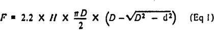
where
F = transmitted force in pounds
H = average Brinell hardness number of the impression bar
D = diameter of the impression ball in millimeters
d = diameter of the impression in millimeters
For the mechanical proof test, evidence of the presence or absence of substantial contact between the shell and the suspension or headform shall be reported.
1 The standard headform may be obtained from:
National Bureau of Standards, Washington, D.C. 20323
Acromedical Laboratory, Wright Air Development Center, Wright-Patterson Air Force Base, Ohio 45433
Nondestructive and Tool Testing Division, Laboratory Branch, Quality Assurance Section, Philadelphia Naval Shipyard. Philadelphia, Pa. 19112
10| Brinell Hardness Number | ||||||||||||||
|---|---|---|---|---|---|---|---|---|---|---|---|---|---|---|
| 18 | 19 | 20 | 21 | 22 | 23 | 24 | 25 | 26 | 27 | 28 | 29 | 30 | ||
| Diameter of impression, millimeters | ||||||||||||||
| 3.9 | 485 | 515 | 540 | 565 | 595 | 620 | 650 | 675 | 700 | 730 | 755 | 785 | 810A | |
| 4.0 | 510 | 540 | 570 | 600 | 625 | 655 | 680 | 710 | 740 | 765 | 795 | 825 | 850 | |
| 4.1 | 540 | 570 | 600 | 630 | 660 | 690 | 720 | 750 | 775 | 810 | 835 | 865 | 895 | |
| 4.2 | 565 | 600 | 630 | 660 | 690 | 720 | 755 | 785 | 815 | 850 | 880 | 910 | 940 | |
| 4.3 | 595 | 625 | 660 | 695 | 725 | 760 | 790 | 825 | 860 | 890 | 925 | 955 | 990B | |
| 4.4 | 625 | 660 | 690 | 725 | 760 | 795 | 830 | 865 | 900 | 935 | 970 | 1000 | 1040 | |
| 4.5 | 650 | 690 | 725 | 760 | 795 | 835 | 870 | 905 | 940 | 975 | 1015 | 1050 | 1085 | |
| 4.6 | 680 | 720 | 760 | 795 | 835 | 870 | 910 | 950 | 985 | 1025 | 1060 | 1100 | 1135 | |
| 4.7 | 715 | 755 | 790 | 830 | 870 | 910 | 950 | 990 | 1030 | 1070 | 1110 | 1150 | 1190 | |
| 4.8 | 745 | 785 | 825 | 870 | 910 | 950 | 990 | 1035 | 1075 | 1115 | 1155 | 1200 | 1240 | |
| 4.9 | 780 | 820 | 865 | 905 | 950 | 995 | 1035 | 1080 | 1125 | 1165 | 1210 | 1255 | 1295 | |
| 5.0 | 810 | 850 | 900 | 945 | 990 | 1040 | 1080 | 1130 | 1175 | 1220 | 1265 | 1310 | 1355 | |
| 5.1 | A845 | 895 | 940 | 985 | 1035 | 1080 | 1130 | 1175 | 1220 | 1270 | 1315 | 1365 | 1410 | |
| 5.2 | 880 | 930 | 980 | 1030 | 1080 | 1125 | 1175 | 1225 | 1275 | 1325 | 1370 | 1420 | 1470 | |
| 5.3 | 920 | 970 | 1020 | 1070 | 1120 | 1175 | 1225 | 1275 | 1325 | 1375 | 1430 | 1480 | 1530 | |
| 5.4 | 955 | 1005 | 1060 | 1115 | 1165 | 1220 | 1270 | 1325 | 1375 | 1430 | 1485 | 1535 | 1590 | |
| 5.5 | B990 | 1045 | 1100 | 1155 | 1210 | 1265 | 1320 | 1375 | 1430 | 1485 | 1540 | 1595 | 1650 | |
| 5.6 | 1030 | 1085 | 1140 | 1200 | 1255 | 1310 | 1370 | 1425 | 1480 | 1540 | 1600 | 1655 | 1710 | |
| NOTE 1: Values below line A exceed or are equal to the specified average force. NOTE 2: Values below line B exceed or are equal to the specified individual force. |
||||||||||||||
8.4 Penetration Resistance Test
8.4.1 Apparatus. The apparatus shall consist of the following:
(1) A standard headform as specified in 8.3.1(1).
(2) A one-pound plumb bob of steel with a point having an included angle of 35 degrees ±1 degree, and a maximum point radius of 0.010 inch.
8.4.2 Mounting of Specimens. Specimens shall be mounted as specified in 8.3.2.
8.4.3 Test Procedures. The headform should be placed on a substantially level concrete floor beneath the plumb bob. The plumb bob shall be dropped ten feet to strike the shell within a three-inch diameter circle, the center of which will be the geometric center of the shall. The plumb bob shall not fall on any ridges or injection points. Penetration shall be measured along the side of the point of the plumb bob and shall include the thickness of the shell.
8.4.4 Reporting. The depth of penetration shall be reported as the average for three specimens.
8.5 Flammability Test. American National Standard Method of Test for Flammability of Self-Supporting Plastics, K65.21-1969 (ASTM D 635-1969),2 shall be employed to determine conformance to 7.5. Three strips shall be used in lieu of the ten specimens required in American National Standard K65.21-1969. The specimens shall be cut from the brim or side of the crown, whichever is thinner.
8.5.1 Reporting. The burning rate, in inches per minute, shall be reported as the average for three specimens.
8.6 Water Absorption Test
8.6.1 Apparatus. The test apparatus shall consist of the following:
(1) An oven of sufficient size where an even and consistent temperature of 120°F can be maintained for at least four hours.
(2) A vessel containing fresh tap water of sufficient size to completely submerge a helmet shell.
8.6.2 Mounting of Specimens. A helmet shall be placed in the oven to heat for at least four hours at 120°F.
8.6.3 Test Procedures. After heat conditioning for at least four hours at 120°F, the shell shall be weighed, then submerged in fresh tap water for 24 hours at atmospheric pressure and room temperature. After removal from the water, the shell shall be wiped lightly with an absorbent cloth or paper towel in order to remove surface moisture and then reweighed.
8.6.4 Reporting. The difference in weight (before and after immersion) multiplied by 100, and divided by the initial weight, equals the percent water absorption.
2 Available from American Society for Testing and Materials, 1916 Race Street, Philadelphia, pa 19103.
11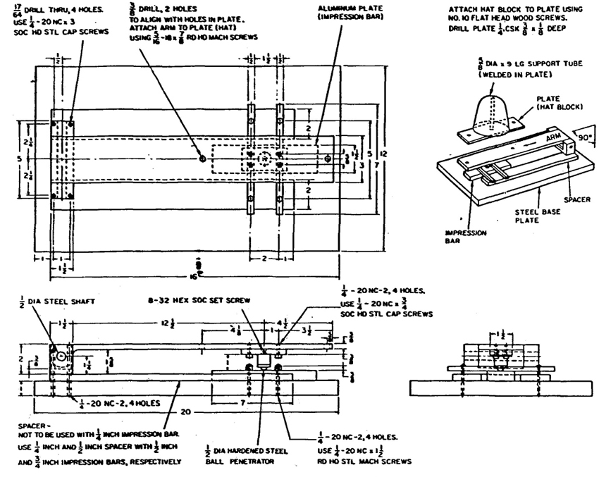
Fig. 1
Brinell Hardness Penetrator Assembly
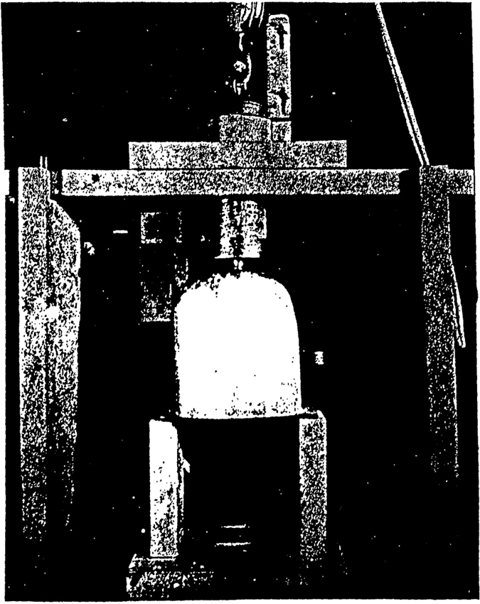
Fig. 2
Suggested Apparatus for Measurement of Crown Clearance
The percent water absorption shall be reported as the average for three specimens.
Revision of American National Standards Referred to in This Document
When the following standards referred to in this document are superseded by a revision approved by the American National Standards Institute, the revision shall apply:
American National Standard Method of Test for Flammability of Self-Supporting Plastics, K65.21-1969 (ASTM D 635-1969)
American National Standard Practice for Occupational and Educational Eye and Face Protection, Z87.1-1968
14(This Appendix is not a part of American National Standard Specifications for Industrial Protective Helmets for Electrical Workers, Class B, Z89.2-1971, but is included for information purposes only.)
Recommendations and Precautions Concerning Helmet Use and Maintenance
Laces, if any, should always be tied securely with a square knot.
A common method of cleaning and sterilizing shells is dipping them in hot water (approximately 140° F), containing a good detergent, for at least a minute. Shells should then be scrubbed and rinsed in clear water (approximately 140° F). After rinsing, the shell should be carefully inspected for any signs of damage.
All components, shells, suspensions, headbands, sweatbands, and any accessories should be visually inspected daily for signs of dents, cracks, penetration, or any other damage due to impact, rough treatment, or wear that might reduce the degree of safety originally provided. Any industrial protective helmet that requires replacement, or replacement of any worn, damaged, or defective part, should be removed from service until the condition of wear or damage has been corrected.
Industrial protective helmets in accordance with this standard are designed to provide optimum protection under average conditions. Users are cautioned that if unusual conditions prevail (such as higher or lower extremes of temperature than described, or other unusual conditions), or if there are signs of abuse or mutilation of the helmet or any component, the margin of safety may be reduced.
Provisions may be made by the manufacturers of industrial protective helmets for extra-small or extra-large sizes.
Industrial protective helmets should not be stored or carried on the rear-window shelf of an automobile since sunlight and extreme heat may adversely affect the degree of protection. Also, in the case of emergency stops or accident, the helmet might become a hazardous missile.
The addition of accessories to the helmet may adversely affect the original degree of protection.
Neither the “mechanical proof test” specified in 8.3.3.2 nor the “minimum breakdown voltage test” requirement specified in 8.2.3 should be construed to mean the safe voltage on which insulating safety headgear may be used. Although insulating safety headgear specified in this standard will provide some protection throughout all voltage ranges, the degree of positive protection will depend upon the user's “factor of safety” applied between the “minimum breakdown voltage” and the voltage on which it is used. The maximum voltage against which insulating safety headgear will protect the wearer depends upon a number of variable factors, such as the characteristics of the electrical circuit and the equipment involved, the care exercised in maintenance of equipment, and weather conditions. Therefore, the safe and proper local use of insulating safety headgear is beyond the scope of this standard.
Insulating safety headgear is not normally intended to be in contact with energized conductors or equipment. Periodic visual inspection and periodic electrical tests are considered necessary and are recommended. This is especially desirable in that this equipment is also used as protection against impact hazards, and dielectric strength may be impaired by impact. Frequency of such tests will depend upon usage, but insulating safety headgear must always be visually inspected before each usage for cracks and signs of impact and rough treatment.
15 16 17The standard in this booklet is one of nearly 4,500 standards approved to date by the American National Standards Institute, formerly the USA Standards Institute.
The Standards Institute provides the machinery for creating voluntary standards. It serves to eliminate duplication of standards activities and to weld conflicting standards into single, nationally accepted standards under the designation “American National Standards.”
Each standard represents general agreement among maker, seller, and user groups as to the best current practice with regard to some specific problem. Thus the completed standards cut across the whole fabric of production, distribution, and consumption of goods and services. American National Standards, by reason of Institute procedures, reflect a national consensus of manufacturers, consumers, and scientific, technical, and professional organizations, and governmental agencies. The completed standards are used widely by industry and commerce and often by municipal, state, and federal governments.
The Standards Institute, under whose auspices this work is being done, is the United States clearinghouse and coordinating body for standards activity on the national level. It is a federation of trade associations, technical societies, professional groups, and consumer organizations. Some 1,000 companies are affiliated with the Institute as company members.
The American National Standards Institute is the United States member of the International Organization for Standardization (ISO), the International Electrotechnical Commission (IEC), and the Pan American Standards Commission (COPANT). Through these channels American Industry makes its position felt on the international level. American National Standards are on file in the libraries of the national standards bodies of more than 50 countries.
For a free list of all American National Standards, write:
American National Standards Institute, Inc
1430 Broadway New York, N. Y. 10018