
In order to promote public education and public safety, equal justice for all, a better informed citizenry, the rule of law, world trade and world peace, this legal document is hereby made available on a noncommercial basis, as it is the right of all humans to know and speak the laws that govern them.
ANSI Z87.1-2003
AMERICAN NATIONAL STANDARD
Occupational and Educational
Personal Eye and Face
Protection Devices

ANSI®
Z87.1-2003
Secretariat
American Society of Safety Engineers
1800 East Oakton Street
Des Plaines, Illinois 60018-2187
Approved June 19, 2003
American National Standards Institute, Inc.
Effective August 19, 2003
1American National Standard
An American National Standard implies a consensus of those substantially concerned with its scope and provisions. An American National Standard is intended as a guide to aid the manufacturer, the consumer, and the general public. The existence of an American National Standard does not in any respect preclude anyone, whether he/she has approved the standard or not, from manufacturing, marketing, purchasing, or using products, processes, or procedures not conforming to the standard. American National Standards are subject to periodic review and users are cautioned to obtain the latest editions.
The American National Standards Institute does not develop standards and will in no circumstances give an interpretation of any American National Standard. Moreover, no person shall have the right or authority to issue an interpretation of an American National Standard in the name of the American National Standards Institute.
CAUTION NOTICE: This American National Standard may be revised or withdrawn at any time. The procedures of the American National Standards Institute require that action be taken to reaffirm, revise, or withdraw this standard no later than five years from the date of approval. Purchasers of American National Standards may receive current information on all standards by calling or writing the American National Standards Institute.
Published by
American Society of Safety Engineers
1800 East Oakton Street, Des Plaines, Illinois 60018-2187
Copyright © 2003 by American Society of Safety Engineers
All rights reserved.
No part of this publication may be reproduced in any form, in an electronic retrieval system or otherwise, without the prior written permission of the publisher.
Printed in the United States of America
2
For additional copies contact:
American Society of Safety Engineers
1800 East Oakton Street
Des Plaines, Illinois 60018-2187
8476-699-2929
(This Foreword is not a part of American National Standard Z87.1-2003)
The history of Z87 began with the first edition of the Z2 standard for head and eye protection and was developed from a set of safety standards originally prepared cooperatively by the War and Navy Departments and the National Bureau of Standards.
The second edition of Z2 was developed by a standards committee organized under the American Standards Association and was published in 1922 as the National Bureau of Standards Handbook H2.
In 1938, Z2 was revised to include respiratory protection and was published as the National Bureau of Standards Handbook H24.
In 1946, Z2 was revised to include advances in safety equipment technology such as the use of plastics for eye protection. Three subcommittees were organized. A subcommittee on eye protection was organized under the supervision of the National Bureau of Standards. A subcommittee on respiratory protection was organized under the supervision of the U.S. Bureau of Mines and a subcommittee for head protection was organized under the Department of the Navy. In 1959, Z2 was approved as the American Standard Safety Code for Head, Eye and Respiratory Protection, Z2.1-1959.
On November 24, 1961, the Standards Safety Board approved to divide the Z2 project into three separate standards: Z87 - Industrial Eye Protection; Z88 - Industrial Respiratory Protection; Z89 - Industrial Head Protection. The Z87.1 Standards Committee under the procedures of the USA Standards Institute, formally the American Standards Association, revised the 1959 version, which was approved on September 18, 1968 as the USA Standard Z87.1 - 1968. The USA Standards Institute changed its name in October 1969 to the American National Standards Institute and the Z87.1 Standard became the American National Standard for Occupational and Educational Eye and Face Protection, ANSI Z87.1 - 1968.
In the Z87 Standards Committee, membership was reconstituted and broadened in 1973 to include all organizations with a substantial interest in the design or use of eye and face protection. The Committee revised the 1968 version, which was approved on February 27, 1979 as the American National Standard for Occupational and Educational Eye and Face Protection, ANSI Z87.1 - 1979.
In 1980 the Z87 Standards Committee reconvened to begin their update of the 1979 version. In order to better accommodate advancements in safety equipment technology more emphasis was placed on developing performance oriented standards. A Bureau of Labor Statistics study revealed that most eye injuries to those wearing protectors were caused by insufficient angular protection. Therefore, angular impact testing requirements were included. In 1983, an American Welding Society study was used to update and improve the transmittance requirements for filter lenses. The standard was approved on February 2, 1989 as the American National Standard Practice for Occupational and Educational Eye and Face Protection, ANSI Z87.1-1989. The standard was subsequently reaffirmed by the Z87 Committee per ANSI procedure in 1998 and is still cited by reference by the U.S. Occupational Safety and Health Administration, (OSHA).
This newest edition of the Z87 Standard is considered by the committee members to be significant, as it will strengthen the impact resistance requirements of the standard while still allowing for future technologies and science. This standard once again while voluntary also offers an enhanced user selection chart, which indicates a system of selecting eyewear appropriate to identified hazards. Of importance to users is the knowledge that different types of products, (spectacles, goggles, and face shields) are tested to different levels of impact resistance, thus, it is incumbent upon the user to select a product being tested to the hazard being exposed to.
Suggestions for improvement of this standard are welcome. They should be sent to the American Society of Safety Engineers, 1800 East Oakton Street, Des Plaines, IL 60018 - 2187.
3This standard was processed and approved for submittal to ANSI by the Accredited Standards Committee on Safety Standards for Eye Protection, Z87. Committee approval of the standard does not necessarily imply that all committee members voted for its approval. At the time it approved this standard, the Z87 Committee had the following members:
Tod Turriff, Chairman
Daniel Torgersen, Vice-Chairman
Timothy R. Fisher, CSP, ARM, CPEA, Secretary
Patrick Arkins, Assistant Secretary
| Organization Represented | Name of Representative |
|---|---|
| Alliance for Telecommunications | Steve Barclay |
| Industry Solutions | |
| American Academy of Ophthalmology | Paul F. Vinger, M.D. |
| American Academy of Optometry | Bernard A. Morewitz, O.D., F.A.A.O. |
| American Ceramic Society | W. Paul Holbrook, Executive Director |
| American Gas Association | Phillip Bennett |
| Kimberly Denbow | |
| American Insurance Association | John Arlington |
| American Optometric Association | Lowell Glatt, O.D. |
| Gregory Good, Ph.D | |
| American Society of Safety Engineers | Jack B. Hirschmann |
| Richard Casey, CSP | |
| American Welding Society | Philip M. Johnson |
| Jean Francois Laterre | |
| Edison Electric Institute | Richard Montgomery, CSP |
| Charles J. Kelly | |
| Glass Lens Council | John Miller |
| Dick Emery | |
| International Safety Equipment Association | John E. Salce |
| Janice Comer Bradley, CSP | |
| National Education Association | Richard Verdugo |
| National Association of Optometrists and Opticians | Lee Handel |
| Franklin D. Rozak | |
| National Institute for Occupational | Larry L. Jackson, Ph. D. |
| Safety and Health (NIOSH) | James R. Harris, P.E. |
| Optical Laboratories Association | Daniel Torgersen |
| Jeffrey Kosh | |
| Opticians Association of America | John M. Young |
| Prevent Blindness America | Tod Turriff |
| Society of the Plastics Industry | Hugh Patrick Toner |
| U.S. Department of Labor/OSHA | Joseph Pipkin |
| U.S. Department of the Air Force | Anthony Okoren, Lt. Colonel |
| U.S. Dept. of the Army | Donald McDuffie, Lt. Colonel |
| U.S. Dept. of the Navy | Dale Barrette, Commander |
| United Auto Workers Union | Jim Howe, CIH |
| Tim McClain | |
| Vision Council of America | Kenneth Wood |
| David Devine | |
| ANSI Z80 Committee Ophthalmic Lenses | Robert Dziuban |
| Jeffrey Kosh | |
| ANSI Z88 Committee Respiratory Protection | William E. Newcomb, CSP |
| Z89 Committee Head Protection | James K. Byrnes |
| Janice C. Bradley, CSP | |
| ICS Laboratories, Inc. | Dale B. Pfriem, Individual Expert |
| Individual Expert | Michael W. Schaus |
| TOPIC | PAGE | |
|---|---|---|
| FORWARD | 2 | |
| 1 | Preface | 9 |
| 2 | Scope, Purpose, Application, Exceptions, Interpretations | 9 |
| 2.1 | Scope | 9 |
| 2.2 | Purpose | 9 |
| 2.3 | Application | 9 |
| 2.4 | Exceptions | 10 |
| 2.5 | Interpretations | 10 |
| 3 | Eye Incident Injury Data/History | 10 |
| 4 | Definitions | 10 |
| 5 | Referenced Publications | 13 |
| 6 | Selection, Use and Maintenance of Protectors | 14 |
| 6.1 | Protectors | 14 |
| 6.2 | Hazard Assessment and Protector Selection | 18 |
| 7 | Spectacles | 22 |
| 7.1 | Introduction | 22 |
| 7.2 | Spectacle Frame Tests | 22 |
| 7.3 | Basic Impact Lens Requirements | 22 |
| 7.4 | Plano Spectacle Lens Requirements | 23 |
| 7.5 | Non-Plano Spectacle Lens Requirements | 24 |
| 7.6 | Flammability | 24 |
| 7.7 | Corrosion Resistance | 25 |
| 7.8 | Cleanability | 25 |
| 7.9 | Replacement Spectacle Lenses | 25 |
| 7.10 | Marking | 25 |
| 8 | Goggles | 26 |
| 8.1 | Introduction | 26 |
| 8.2 | Impact Testing Requirements | 26 |
| 8.3 | High Impact Testing Requirements | 27 |
| 8.4 | Optical Requirements for Plano Goggle Lenses | 27 |
| 8.5 | Optical Requirements for Non-Plano Goggle Performance | 28 |
| 8.6 | Flammability | 28 |
| 8.7 | Corrosion Resistance | 28 |
| 8.8 | Cleanability | 28 |
| 8.9 | Ventilation Requirements | 28 |
| 8.10 | Transmittance of Non-Lens Areas | 28 |
| 8.11 | Replacement Goggle Lenses | 28 |
| 8.12 | Marking | 29 5 |
| 9 | Faceshields | 29 |
| 9.1 | Introduction | 29 |
| 9.2 | Impact Testing Requirements | 30 |
| 9.3 | High Impact Testing Requirements | 30 |
| 9.4 | Optical Requirements for Plano Faceshield Windows | 31 |
| 9.5 | Requirements for Wire-Screen Windows | 31 |
| 9.6 | Flammability | 31 |
| 9.7 | Corrosion Resistance | 31 |
| 9.8 | Cleanability | 32 |
| 9.9 | Replacement Faceshield Windows | 32 |
| 9.10 | Marking | 32 |
| 10 | Welding Helmets and Handshields | 33 |
| 10.1 | Introduction | 33 |
| 10.2 | Impact Testing Requirements | 33 |
| 10.3 | High Impact Testing Requirements | 34 |
| 10.4 | Optical Requirements for Plano Welding Helmet Lenses | 34 |
| 10.5 | Optical Requirements for Non-Plano Welding Helmet Lenses | 35 |
| 10.6 | Flammability | 35 |
| 10.7 | Corrosion Resistance | 35 |
| 10.8 | Cleanability | 35 |
| 10.9 | Non-Lens Area Transmittance and Light Tightness | 35 |
| 10.10 | Replacement Welding Helmet Lenses | 35 |
| 10.11 | Marking | 36 |
| 10.12 | Transmittance Requirement, Automatic Darkening Welding Filter Lenses | 36 |
| 10.13 | Cover Lenses | 37 |
| 11 | Respirators | 37 |
| 11.1 | Introduction | 37 |
| 11.2 | Full Facepiece Respirators | 37 |
| 11.3 | Loose Fitting Respirators | 37 |
| 11.4 | Full Facepiece Welding Respirators | 37 |
| 11.5 | Loose Fitting Welding Respirators | 37 |
| 12 | Transmittance Requirements for Clear Lenses, Filter Lenses and Automatic Darkening Filter Lenses | 37 |
| 12.1 | Formulae | 38 |
| 12.2 | Transmittance Requirements | 39 |
| 12.3 | Switching Index Requirements | 41 |
| 13 | Instructions, Use and Maintenance | 42 |
| 13.1 | General Requirements | 42 |
| 13.2 | Instructions | 42 |
| 13.3 | Inspections | 42 |
| 13.4 | Maintenance | 42 |
| 13.5 | Care | 42 |
| 13.6 | Training | 42 6 |
| 14 | Test Methods | 42 |
| 14.1 | High Mass Impact Test | 43 |
| 14.2 | High Velocity Impact Test | 43 |
| 14.3 | Tests for High Impact Prescription Lenses | 44 |
| 14.4 | Drop-Ball Impact Test | 45 |
| 14.5 | Penetration Test | 46 |
| 14.6 | Flammability Test | 47 |
| 14.7 | Corrosion Resistance Test | 47 |
| 14.8 | Cleanability Test | 47 |
| 14.9 | Prismatic Power Test | 48 |
| 14.10 | Refractive Power, Resolving Power and Astigmatism Tests | 48 |
| 14.11 | Haze Test | 49 |
| 14.12 | Transmittance Test | 49 |
| 14.13 | Switching Index Test | 49 |
| 14.14 | Light Tightness Test | 50 |
| 15 | Warning Label | 51 |
| 15.1 | Purpose | 51 |
| 15.2 | Label or Tag Requirements | 51 |
| TABLES | ||
| Table 1 – Transmittance Requirements for Clear and Filter Lenses | 40 | |
| Table 2 – Transmittance Requirements for Special-Purpose Lenses | 41 | |
| Table 3 – Switching Index Requirements for Automatic Darkening Welding Filter Lenses | 41 | |
| FIGURES | ||
| Figure 1 – Spectacles | 14 | |
| Figure 2 – Temples | 14 | |
| Figure 3 – Fronts | 14 | |
| Figure 4 – Bridges | 15 | |
| Figure 5 – Side Protection | 15 | |
| Figure 6 – Life-front spectacles | 16 | |
| Figure 7 – Goggles | 16 | |
| Figure 8 – Faceshield | 17 | |
| Figure 9 – Welding Helmets | 18 | |
| ANNEXES | ||
| Annex A – Spectral Factor Tables (normative) | 52 | |
| Annex B – Test Apparatus (normative) | 56 | |
| Annex C – Test Apparatus (informative) | 58 | |
| Annex D – Calibration of Test Telescope (informative) | 60 | |
| Annex E – Sources for Test Apparatus (informative) | 61 | |
| Annex F – Referenced Publications (informative) | 62 | |
| Annex G – Required Marks and Marking Locations by Product Category (informative) | 63 | |
| Annex H – Eye Injury Report Form (informative) | 64 | |
| Annex I – Selection Chart | 67 | |
American National Standard Z87.1-2003 uses a column format to provide both specific requirements and supporting information.
Operating rules (safe practices) are not included, unless they are of such a nature as to be vital safety requirements, equal in weight to other requirements, or guides to assist in compliance with the standard.
The information and materials contained in this publication have been developed from sources believed to be reliable. However, the American Society of Safety Engineers (ASSE) as secretariat of the ANSI accredited Z87 Committee or individual committee members accept no legal responsibility for the correctness or completeness of this material or its application to specific factual situations. By publication of this standard, ASSE or the Z87 Committee does not ensure that adherence to these recommendations will protect the safety or health of any persons, or preserve property.
8American National Standard Occupational and Educational Personal Eye and Face Protection Devices
This standard for personal eye and face protective devices (hereinafter referred to as protectors) is, as far as possible, designed to be performance oriented. Every effort was made to develop requirements that are consistent with, or more stringent than, ANSI Z87.1-1989(R-1998). This standard recognizes the Bureau of Labor Statistics1 study that revealed the need for angular protection, in addition to frontal protection, in eye and face protectors worn in the occupational setting.
Protectors do not provide unlimited protection. In the occupational and educational environment, protectors are not substitutes for machine guards and other engineering controls. Protectors alone should not be relied on to provide complete protection against hazards, but should be used in conjunction with machine guards, engineering controls, and sound safety practices. Every effort should be made to eliminate eye and face hazards in occupational and educational settings.
In 1992, the Occupational Safety and Health Administration began regulating occupational exposure to bloodborne pathogens and, as a result, now require employers to provide personal protective equipment (PPE) including eye and face protection for employees exposed to these hazards. At the time of the publication of this standard, no standards existed for eye and face protection intended to provide protection from bloodborne pathogens. Nevertheless many employers have elected to provide their employees with PPE conforming to the requirements of ANSI Z87. These products may or may not provide adequate protection against bloodborne pathogens.
Extreme caution must be exercised in the selection and use of personal protective equipment in applications for which no performance requirements or standardized testing exists.
This standard sets forth criteria related to the description, general requirements, testing, marking, selection, care, and use of protectors to minimize or prevent injuries, from such hazards as impact, non-ionizing radiation and chemical type injuries on occupational and educational environments including, but not limited to, machinery operations, material welding and cutting, chemical handling, and assembly operations.
This standard provides minimum requirements for protectors including selection, use, and maintenance of these protectors as devices to minimize or prevent eye and face injuries.
2.3.1 The requirements of this standard apply to protectors when first placed in service.
2.3.2 Protectors bearing the marking Z87 or represented in any way as being in compliance with this standard, shall meet all requirements of this standard in their entirety. All components of eye and face protective devices shall comply with the requirements of this standard.
2.3.3 Compliance with this standard cannot always be assured when replacement components are used. End users shall exercise extreme care in the selection and installation of replacement components to ensure compliance with this standard.
1 “Accidents Involving Eye Injuries,” U.S. Department of Labor, Bureau of Labor Statistics, April 1980, Report 597.
92.3.4 Components bearing the marking Z87 shall not be used with non- complying components.
2.3.5 The use of a device that is not in compliance with this standard or the use of a protector in applications outside its scope, may result in serious injury or death.
2.4.1 This standard does not apply to hazardous exposure to bloodborne pathogens, X-rays, high-energy particulate radiation, microwaves, radio-frequency radiation, lasers, masers, and sports, nor does it address comfort and/or appearance features.
2.4.2 This standard, by setting forth its requirements, points out the need to exercise caution in the selection and use of protectors where no performance requirements or standardized testing exist. For example, these protectors may not provide adequate protection against bloodborne pathogens.
Request for interpretations of this standard shall be in writing and addressed to the secretariat of this accredited standards committee.
End users are encouraged fill out an injury report form (Annex H), if there is an incident involving an eye injury. Filling out and submitting the report will enable the committee to build a history, identify potential opportunity areas for standard revisions and increase protection. The report should be sent to American Society of Safety Engineers (ASSE) 1800 East Oakton Street Des Plaines, IIIinois 60018.
For purposes of this standard, the following definitions shall apply:
astigmatism. A condition in a lens of a protector in which there is a difference in refractive power in one meridian from that in another meridian.
Basic Impact Protectors /Lenses. Protectors that are used only in an environment where the known or presumed hazards are of low impact nature.
blue-light transmittance. Transmittance of optical radiation weighted by its ability to cause photochemical damage to the retina.
chin protector. That portion of a device that offers protection to a wearer's chin, lower face and neck.
cleanability. The ability to be made readily free of dirt or grime without being damaged.
cover lens/plate. See “lens/plate, cover”
crown protector. That portion of a device that offers protection to a whearer's forehead.
crown strap. That portion of a headgear that rests on the top of the head.
dark state. The lowest operating luminous transmittance of an automatic darkening filter lens.
diopter (D). A unit of measurement (plus or minus) used to express the power of a lens. It is expressed as the reciprocal of the focusing distance given in meters. The diopter is also used to express the curvature of surfacing tools and the refracting power of curved surfaces.
effective far-ultraviolet transmittance. Transmittance of optical radiation weighted by its ability to damage the cornea with wavelengths from 200 to 315 nanometers.
10faceshield. A protective device commonly intended to shield the wearer's face, or portions thereof, in addition to the eyes, from certain hazards, depending on faceshield type. Faceshields shall be used only in conjunction with spectacles and /or goggles.
faceshield, wedding. A faceshield intended for limited welding applications. Faceshields shall be used only in conjunction with spectacles and/or goggles.
filter lens. See “lens, filter”.
fracture. A lens will be considered to have fractured if it cracks through its entire thickness into two or more separate pieces, or if any lens material visible to the naked eye becomes detached from the inner surface.
frame. A device, which holds the lens or lenses on the wearer.
front. The part of a spectacle or goggle frame that is intended to contain the lens or lenses.
glare. Uncomfortably bright light without hazardous levels of ultraviolet or infrared radiation.
goggle. A protective device intended to fit the face surrounding the eyes in order to shield the eyes from certain hazards, depending on goggle type.
goggle, welding. A goggle intended for limited welding applications.
handshield. A hand-held welding helmet. See “welding helmet”.
haze. The percent of incident light that is not transmitted in a straight line through the lens but forward scattered, greater the 2.5° diverging.
headgear. That part of a protective helmet, hood, or faceshield that supports the device on the wearer's head.
High Impact Protectors/Lenses. Protectors that are used in an environment where the known or presumed hazards are of high velocity of high mass or a high impact nature.
hood. A device that completely covers the head, neck, and portions of the shoulders.
infrared radiation (IR). As related to this standard, electromagnetic energy with wavelengths from 780 to 2000 nanometers.
interpupillary distance (PD). The distance in millimeters between the centers of the pupils of the eyes.
lens. The transparent part of a protective device through which the wearer sees, also referred to as a plate or window for some devices.
lens, automatic darkening welding filter. A filter lens, which automatically switches from a light state to a dark state in response to a change of light intensity.
lens, cover. An expendable lens used to protect another lens surface from damage.
lens, filter. A lens that attenuates specific wavelengths of ultraviolet, visible, and infrared radiation.
lens, impact-resistant. A lens capable of withstanding the appropriate impact tests of this standard.
lens, non-removable. A lens and holder that are homogeneous and continuous.
lens, photochromic. A lens, which darkens when exposed to, and fades when removed from, ultraviolet radiation and/or sunlight.
lens, non-plano. Lenses made to an individual prescription (Rx/prescription ophthalmic) or lenses using non-prescription, non-plano lenses for magnifying purposes.
11lens, plano (non-Rx). A lens that does not incorporate a corrective prescription; this lens is not necessarily flat. A plano lens is sometimes called afocal.
lens, polarizing. A lens, which transmits light preferentially in particular planes of orientation.
lens, prescription (Rx). A lens manufactured to the wearer's individual corrective prescription.
lens, tinted. A lens with color such as amber, smoke, or cobalt, which does not meet the requirements of Table 1.
lens, welding filter. A lens specified for use for welding or brazing.
lift-front. A type of supplementary lens and holder that covers the viewing area of a protector immediately in front of the wearer's eyes and that can be positioned outside the line of sight.
light. Optical radiation weighted by its ability to cause visual sensations.
light state. The highest operating luminous transmittance of an automatic darkening welding filter lens.
luminous transmittance (TL). The fraction of light (380-780 nm) passing through a medium.
lux (lx). A unit of measurement of illuminance equal to one lumen per square meter of the illuminated surface.
millisecond (ms). One thousandth of a second; 10−3 second.
nanometer (nm). A unit of measurement of wavelength equal to one billionth of a meter; 10−9 meter.
NIOSH. National Institute for Occupational Safety and Health, the federal agency responsible for, among other things, certifying the respiratory protective properties of respirators.
optical density. A measure of the transmittance of an optical device.
optical radiation. As related to this standard, that portion of the electromagnetic spectrum ranging in wavelength from 200 nm to 2000 nm, having the nominal sub-intervals: UV-C (200-280 nm), UV-B (280-315 nm), UV-A (315-380 nm), VISIBLE (380-780 nm), IR-A (780-1400 nm), IR-B (1400-3000 nm), and IR-C (3000 nm-1 mm).
plano. See “lens, plano”.
power. See “refractive power”, “resolving power”, and “prismatic power.”.
prismatic power, “prism”. A measure of the angular deviation expressed in prism diopters(Δ) of a light ray after passing along the viewing path through a lens. (One prism diopter equals deviation of 1 cm per meter of path length.)
protective device, “protector”. A complete product meeting the requirements of this standard.
protective helmet. Headwear conforming to ANSI Z89.1-1997, or the latest revision thereof; also known as a “hard that”.
refractive power, “power”. A measure of the ability of a lens to focus light rays, expressed in diopters (D).
resolving power, “definition”. The measure of the ability of a lens to form separate distinct images of two objects close together.
respirator, full facepiece. A tight fitting respirator that covers the nose, mouth and eyes from approximately the hairline to below the chin.
12respirator, loose fitting. A respiratory inlet covering that is designed to form a partial seal with the face, or that completely covers the head and neck, and may cover portions of the shoulder.
respirator, welding. A respirator intended to provide optical radiation protection for welding operations.
retained. In this standard, the use of the word “retained” means that the lens does not separate from the frame by more the 25% of its periphery.
shall. In this standard, the use of the word “shall” indicates a mandatory requirement.
should. In this standard, the use of the word “should” indicates a recommendation.
sideshield. A part of, or attachment to, a spectacle that provides side impact resistance.
spectacles. A protective device intended to shield the wearer's eyes from certain hazards, depending on the spectacle type.
switching index. The response time of an automatic darkening welding filter lens.
temple. That part of a spectacle frame commonly attached to the front and generally extending behind the ear of the wearer.
type tests. One or more tests performed on an item to approve a material, construction, model or design to determine if it is capable of meeting the requirements of a product standard.
ultraviolet radiation (UV). In this standard, electromagnetic energy with wavelengths from 200 to 380 nanometers.
welding goggle. See “goggle, welding”.
welding faceshield. See “faceshield, welding”.
welding faceshield. A protective device intended to provide protection for the eyes and face against optical radiation and weld spatter, which shall be worn only in conjunction with spectacles or goggles.
window. The lens portion of a faceshield (see “lens”).
window, non-removable. A window and holder that are homogeneous and continuous.
The following standards contain provisions, which, through reference in this text, constitute mandatory provisions, of this standard. Other reference materials, which do not contain mandatory provisions, are listed in Annex F.
American Conference of Governmental Industrial Hygienists - ““Relative Spectral Effectiveness by Wavelength”- 1993-1994.
ANSI Z80.1-1999, American National Standard for Opthalmics - Prescription Opthalmic Lenses - Recommendations.
ANSI Z80.5-1997, American National Standard Requirements for Dress Ophthalmic Frames.
ASTM D635-1998, Test Method for Rate of Burning and/or Extent and Time of Burning of Self-Supporting Plastics in a Horizontal Position.
ASTM D1003-00, Standard Test Method for Haze and Luminous Transmittance of Transparent Plastics.
ASTM D2240-2002, Standard Test Method for Rubber Property - Durometer Hardness.
ASTM D412-1998a, Standard Test Method for Vulcanized Rubber and Thermoplastic Rubbers and Thermoplastic Elastomers - Tension.
NBS Special Publication 374.
13Protectors are personal protective devices designed to protect the wearer from potential hazards that could adversely affect a person's eyes and/or face. Depending on the potential hazard, the protector may be designed to block flying objects or hazardous liquids, filter optical radiation, or enhance the wearer's vision for performing certain visual tasks. It is also important to realize that different categories are tested at different levels of impact resistance. There are three categories of protector lenses based on transmittance: clear, filter and special purpose (tables 1 and 2). There are many types of protectors available. In the following sections, illustrations of various types of devices used to protect the eyes and face are provided for guidance only; they are not intended to show every type of device available.
6.1.1 Spectacles and Spectacle Components
Spectacles are protective devices designed to shield the wearer's eyes from various impact, or impact and optical radiation hazards. A spectacle commonly consists of the following components: a front, a lens or lenses, a pair of temples, and side protection (figure 1). Spectacle components can be assembled in various combinations to make a complete protector to provide the user with a wide selection of suitable equipment for differing applications.

Figure 1 - Spectacles
6.1.1.1 Temples
A temple (figure 2) is that component of a spectacle that extends from the front to just behind the wearer's ear or continues completely around the wearer's head and is used to secure the frame in its proper use position. Temples are usually hinged at the front to permit easy storage when not in use and they are commonly available in the following three types: (1) spatula temples, (2) cable temples, and (3) headband temples. To properly fit the wide variety of wearers, temples are adjustable and/or available in various lengths.

Figure 2 - Temples: spatula, cable and headband
6.1.1.2 Fronts
The front (figure 3) is that component of a spectacle that retains the lens or lenses in the proper orientation for viewing. The front can be a separate part from the lens (removable lens type) or can be molded as an integral part of the lens (non-removable lens type). Frames for prescription lenses usually incorporate the removable type lens front. Cover spectacles are typically the non-removable lens type.

Figure 3 - Fronts: Spectacles with non-removable lenses
146.1.1.3 Lenses
Lenses are that component of a spectacle through which the wearer sees and which provides a protective barrier. Lenses are available in various materials, shapes, thicknesses, shades and tints depending on their particular application. Lenses also can be made to refract or bend light to magnify an object or provide corrective vision to a wearer's individual prescription (Rx). Lenses that do not refract light are considered “plano” and do not provide corrected vision.
6.1.1.4 Bridges/Nose Piece
A bridge or nose piece (figure 4) is that component of a spectacle, which supports the front on a wearer's face and typically rests on the bridge of the wearer's nose. Bridges are commonly available in three types: (1) fixed bridge (non-adjustable), (2) universal/saddle, and (3) adjustable nose pad. Bridge sizes are expressed in millimeters and measured as the distance between lenses (DBL).

Figure 4 - Bridges: fixed and adjustable nose pad
6.1.1.5 Side Protection
Side protection (Figure 5) is that component of a spectacle that extends from the front to some distance between the front and the wearer's ear and provides limited protection to the wearer's eyes from lateral hazards. Side protection may be an integral part of the frame or lens, a separate sideshield that is permanently attached to the frame, or a removable part of the frame. The function and coverage of side protection are defined by the high velocity impact test (section 14.2).

Figure 5 - Side Protection: flatfold sideshields and detachable sideshields
6.1.1.6 Special Purpose Spectacles
Special purpose spectacles are those which use lenses designed for a specific application. Examples of products for such applications include, but are not limited to, sunglasses, notch filters (e.g. - didymium containing), and furnace glasses. Special purpose spectacles use lenses that meet the requirements of table (2).
6.1.1.7 Lift-Front Spectacles
A lift-front spectacle (figure 6) is a spectacle conforming to the requirements of this standard that has an additional permanent or removable front attached, that can be raised or lowered to the wearer's line of sight. The lift-front component is typically used to provide additional protection, as needed, from glare, optical radiation, or both, or is used for special viewing tasks, such as magnification, and is marked accordingly. Lift-front spectacles are
15evaluated for impact and optical performance with the lift-front in the up position. The lift-front lens is evaluated for optical performance requirements of 7.4 or 7.5.

Figure 6 - Lift-front spectacles
6.1.2 Goggles and Goggle Components
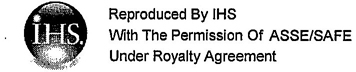
Goggles are protective devices designed to fit snugly but not necessarily seal completely to a wearer's face surrounding the wearer's eyes in order to shield the eyes. Goggles provide more protection than spectacles from impact, dust, liquid splash and optical radiation hazards. A goggle commonly consists of the following components: a frame, a lens or lenses, ventilation area and headband.
Goggles (figure 7) are commonly available in two styles: (1) eyecup goggles that cover the eye sockets completely; and (2) cover goggles, which may be worn over spectacles. Goggles are commonly available with rigid or flexible frames and are usually ventilated to minimize fogging. Three different types of ventilation are available: (1) direct ventilation, (2) indirect ventilation, and (3) goggles with no ventilation provision. Direct ventilated goggles permit the direct passage of air from the work environment into the goggle and are not recommended for use in protection against liquid splash hazards. Indirect ventilated goggles permit the passage of air and may prevent the direct passage of liquids and/or optical radiation. Goggles with no provision for ventilation minimize passage of dusts, mist, liquid splash and vapor. Goggles are available in many configurations to provide the user with a wide selection of suitable equipment.
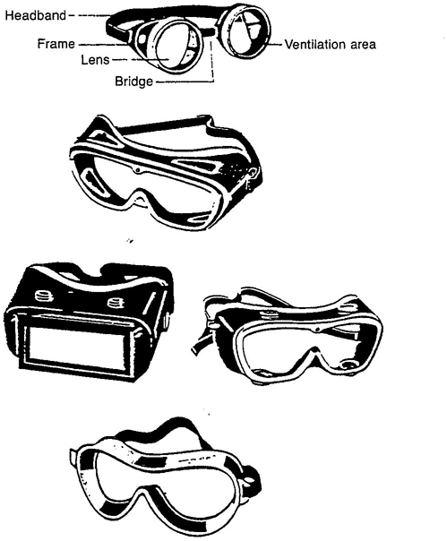
Figure 7 - Goggles: eyecup goggle (showing components), cover goggles with direct ventilation, and indirect ventilation, and non-ventilated goggles
6.1.2.1 Side Protection
Side protection is that component of a goggle that extends from the front to some distance between the front and the wearer's ear and provides limited protection to the wearer's eyes from lateral hazards. Side protection in goggles is commonly an integral part of the frame or lens. The function and coverage of side protection are defined by the high velocity impact test (section 14.2).
6.1.2.2 Lift Front
A lift-front goggle is a goggle conforming to the requirements of this standard that has an additional permanent or removable front attached, that can be raised or lowered to the wearer's line of sight. The lift-front-component is typically used to provide additional protection, as needed, from glare, optical
16radiation, or both, or is used for special viewing tasks, such as magnification, and is marked accordingly. Lift-front goggles are evaluated for impact and optical performance with the lift-front in the up position. The lift front lens is evaluated for optical performance requirements of 8.4 or 8.5
6.1.2.3 Special Purpose Goggles
Special purpose goggles are those which use lenses designed for a specific application. Examples of products for such applications include, but are not limited to, notch filters (e.g.-didymium containing) and furnace goggles. Special purpose goggles use lenses that meet the requirements of table 2.
6.1.3 Faceshields and Faceshield Components
Faceshields are protective devices designed to shield the wearer's face, or portions thereof, in addition to the eyes, from various hazards. Facesheilds shall be used only in conjunction with spectacles and/or goggles and provide a higher level of protection than spectacles or goggles alone. Faceshields are used to provide protection from impact, dust, liquid splash and optical radiation hazards. Facehields (figure 8) may be used with a headgear assembly designed to suspend a transparent window that surrounds and shields the wearer's face. Faceshields may be incorporated with head protection. Faceshields also may provide neck and chin protectors. The assembled devices are available in many combinations of the various component types to provide the user with a wide choice of suitable equipment.
Figure 8 - Faceshield
6.1.3.1 Faceshield Windows
Faceshield windows provide a protective barrier between the work environment and the wearer's eyes and face. Faceshields are available in various materials, shapes, thickness, shades and tints depending on their particular application. Commonly available windows are plastic, plastic with a glass insert, or a wire screen.
6.1.3.2 Special Purpose Facehields
Special purpose faceshields are those which use windows designed for a specific application. Special purpose faceshields may provide limited protection from impact hazards, optical radiation, or both. Special purpose faceshields meeting certain light transmittance requirements are marked as “light”, “medium”, or “dark” (section 9.4.5) or meet the requirements of table 2.
6.1.4 Welding Helmets and Handshields
Welding helmets and handshields are protective devices designed to provide protection to a wearer's eyes, face, ears, and front of the neck against optical radiation and weld spatter. Welding helmets and handshields shall be used only in conjunction with spectacles, goggles, or both. There are three types (figure 9) commonly available: (1) helmet with stationary lens, (2) lift-front helmet; and (3) handshield. A welding helmet may be mounted on a protective helmet with special accessories. A welding helmet may be the respiratory inlet covering of a loose fitting facepiece respirator.
17
Figure 9 - Welding helmets: helmet with stationary lens, lift-front helmet and handshield
6.1.4.1 Special Purpose Lenses and Windows
Special purpose lenses are designated as such because they do not meet the transmittance requirements of table 1, but do meet the transmittance requirements of table 2. A typical example is a cobalt furnace lens.
Special purpose lenses and windows are further classified and marked in accordance with the requirements of section 10.11. Only devices meeting the applicable sections of this standard shall be used with special purpose lenses. (For additional information, see ANSI Z49.1-1999.)
6.1.5 Respirators
Full facepiece respirators are NIOSH-approved, tight fitting respirators designed to provide a complete seal with the face and to provide protection to the wearer's eyes from impact hazards in addition to eye irritants. Loose fitting respirators are NIOSH-approved respirators designed to provide a partial seal with the face and to provide protection to the wearer's eyes from impact hazards in addition to eye irritants. Welding respirators are NIOSH-approved respirators designed to provide protection to the wearer's eyes from impact and optical radiation hazards in addition to eye irritants. Depending on the type of welding, the respirator may be designed to provide protection to the face, ears and front of the neck against optical radiation and weld spatter.
6.2.1 General Requirements
Protectors shall be required where there is a reasonable probability of an eye or face injury that could be minimized or prevented by the use of such protection. In such cases, employers and educational authorities shall make eye and face protectors conveniently available to employees and students for their use in the work environment, per applicable federal and state regulations. The employees and students shall use such devices. Where there is a reasonable probability of impact from flying objects, a protector with side protection shall be required.
Protectors are not substitutes for engineering controls and sound safety practices. Protectors alone should not be relied upon to provide the sole means of protection against eye and face hazards. Protectors shall be used in conjunction with engineering controls and sound safety practices. Known hazards should be removed or minimized to the extent possible.
Employers and employees should consult their federal, state and local safety and health regulatory authorities to become knowledgeable of the legal requirements applicable to their area. Under the Department of Labor, the Federal Occupational Safety and Health Administration (Fed OSHA) has codified in 29 Code of Federal Regulations (CFR) 1910 Occupational Safety and Health Standards for General Industry, and 29 CFR 1926 Occupational Safety and Health Standards for the Construction Industry specific legal requirements and guidelines that employers must follow to protect their employees adequately (see specifically 29 CFR 1910.133
18and 29 CFR 1926.102). By law, state and local government authorities can implement their own safety and health regulations if they are at least as protective as the federal regulations.
6.2.2 Hazard Assessment
It is necessary to consider certain general guidelines for assessing the eye and face hazard situations that exist in the work environment and to match the protective device to the particular hazard. The person directly responsible for a safety program should apply common sense and fundamental technical principles to accomplish these tasks. This process is subjective by nature because of the infinite variety of situations where face and eye protection may be required. At a minimum, the following recommended hazard assessment procedure should be followed in order to assess the need for eye and face protective equipment.
(1) Survey the Work Area. Conduct a walk-through survey of the area. The purpose of the survey is to identify sources of potential eye and face hazards. Consideration should be given to the six hazard categories addressed by this standard:
Impact
Heat
Chemical (Liquid Splash)
Dust
Glare
Optical Radiation(2) Identify Sources of Hazards. During the walk-through survey observe:
(a) Sources of motion; i.e., machinery or processes where any movement of tools, machine elements or particles could exist, or movement of personnel that could result in collision with stationary objects.
(b) Sources of high temperatures that could result in facial burns, eye injury or ignition of protective equipment, etc.
(c) Types of chemical exposures.
(d) Sources of dust.
(e) Sources of optical radiation, i.e., welding, brazing, cutting, furnaces, heat treating, high intensity light sources and ultraviolet lamps.
(f) Layout of workplace and location of other personnel.
(g) Any electrical hazards.(3) Organize Data. Following the walk-through survey, organize the data and information for use in the assessment of hazards. The objective is to prepare for an analysis of the hazards in the environment to enable proper selection of protective equipment.
(4) Analyze Data. Having gathered and organized data on a workplace, make an estimate of the potential for eye and face injury. Each of the basic hazards should be reviewed and a determination made as to the type and level of each of the hazards found in the area. The possibility of exposure to several hazards simultaneously should be considered.
(5) Selection. Specify the protector(s) suitable for the hazards identified (see Selection Chart, Annex I-Attached at the end of the standard).
(6) Reassessment of Hazards. A periodic reassessment of the work area should be performed on a regular basis to identify changes in the hazard situation that could affect the level of protection required. Reassess the workplace hazard situation by identifying and evaluating new equipment and processes, reviewing accident records, and reassessing the suitability of previously selected eye and face protection.
6.2.3 Protector Selection
After completing a thorough hazard assessment of the environment such as recommended in section 6.2.2, the general procedure for selection
19of protective equipment is as follows:
(1) Become familiar with the Selection Chart (Annex I - Attached at the end of the standard), the types of protective equipment that are available, their capabilities and limitations.
(2) Compare the hazards associated with the environment, i.e., impact velocities, masses, projectile shape, radiation intensities, etc., with the available protective equipment.
(3) Make a judgment in selection of the appropriate protective equipment so that the protection is consistent with the reasonably probable hazard.
(4) Basic impact protectors (lenses) may be used only in an environment where the known or presumed hazards are of low velocity, low mass and low impact nature. High impact protectors shall be used in an environment when the known or presumed hazards are of a high velocity, high mass or high impact nature.
(5) Provide and fit the user with the protective device and provide instruction on its care, use and limitations as recommended in sections 6.2.4 and 6.2.6.
(Note: Be aware that spectacles, goggles, and face shields are tested with different impact criteria so the protector selection should be consistent to the testing.)
The Selection Chart (Annex I - Attached at the end of the standard) is intended to aid in identifying and selecting the types of eye and face protectors that are available. The capabilities and limitations for the hazard “source” operations are listed in this guide. This guide is not intended to be the sole reference in selecting the proper eye and face protector.
6.2.4 Product Use and Limitations
Protectors are a personal item. They should be issued for exclusive use by a particular individual. However, in circumstances where protectors are reissued, the protectors shall be maintained in a sanitary and reliable condition as described in section 6.2.6.
Employers and educational authorities should train their employees and students in the proper use, care, application, inspection, maintenance, storage, and limitations of protective devices and provide them with all warnings, cautions, instructions and limitations.
included with the protector by the manufacturer. The wearer should follow all instructions provided by the manufacturer.
Caution shall be exercised to ensure that the level of protection provided by any protector is adequate for its intended purpose.
See the Selection Chart (Annex I - Attached at the end of the standard), for information on specific applications.
For more information regarding training please review the American National Standard, Z490. 1-2001, “Criteria for Accepted Practices in Safety, Health, and Environmental Training”.
6.2.4.1 Special Purpose Protectors and Lenses
Special purpose protectors and lenses are those which meet the requirements of table 2, but do not meet the requirements of table 1. They are designed for specific applications. They might not provide adequate ultraviolet protection, infrared protection, or ultraviolet and infrared protection when used for applications for which they are not designed. Therefore, special purpose protectors and lenses shall be used only after a complete hazard assessment and at the discretion of the individual responsible for the selection of protectors.
206.2.4.2 Prescription (Rx) Eyewear
Wearers of prescription (Rx) eyewear shall wear eye protection that incorporates the prescription in its design or that can be worn over prescription lenses without disrupting either the prescription eyewear or the protective eyewear.
Contact lens wearers should recognize that dusty and/or chemical environments may represent an additional hazard. Contact lenses are not protective devices. Wearers of contact lenses shall wear appropriate protectors in hazardous environments.
6.2.4.3 Filter Lenses and Windows
A filter lens meets the ultraviolet, luminous and infrared transmittance requirements of table 1 and is marked with a shade number that indicates its transmittance levels in accordance with table 1. Filter lenses of an appropriate shade are suitable for protection from sources of very high radiance, such as welding arcs. Filter lenses are also suitable for protection from sources of low radiance, provided that they are not so dark as to interfere with normal visual performance of the task.
6.2.4.4 Tinted Lenses and Windows
Lenses having low luminous transmittance should not be worn indoors, except when needed for protection from optical radiation. Care should be exercised in conjunction with wearing such lenses for driving vehicles with tinted windshields or for night driving. Some polarized lenses may present viewing problems when reading liquid crystal displays. Some tinted lenses may absorb certain wavelengths of visual displays or signs, rendering them unreadable.
6.2.4.5 Photochromic Lenses
Photochromic lenses darken when exposed to, and fade when removed from, ultraviolet radiation or sunlight. They are frequently used to provide comfortable vision for a wide range of ambient illumination. They should be used with care where the wearer passes from outdoors to indoors in the course of the job. Photochromic lenses that do not meet the transmittance requirements of table 1 and the switching index requirements of table 3 are not suitable for protection from direct exposure to high radiance sources (e.g., welding arcs and unshielded high intensity lamps). Photochromic lenses that do not meet the switching index requirements in table 3 are not automatic darkening welding filters. Photochromic lenses shall be used only after a complete hazard assessment and at the discretion of the person responsible for the selection of protectors, (See the Selection Chart, Annex I - Attached at the end of the standard.)
6.2.4.6 Protection from Low Radiance Sources of Ultraviolet and Visible Radiation
Some lenses that comply with the transmittance requirements of table 2, but not with all of the requirements of table 1, can provide sufficient ultraviolet attenuation to be used for protection from direct exposure to ultraviolet sources of low radiance and from indirect exposure (i.e., scattered radiation) to properly shielded ultraviolet sources of high radiance. Lenses that have some attenuation of visible light may also be suitable for protection from scattered light from properly shielded high radiance sources of visible light, (See Selection Chart, Annex I - Attached at the end of the standard.)
6.2.5 Fitting the Device
Careful consideration should be given to comfort and fit. Protectors that fit poorly will not afford the protection for which they were designed. Protectors should be fitted by qualified personnel. Continued wearing of protectors is more likely when they fit the wearer comfortably. Protectors are generally available in a variety of styles and sizes and care should be taken to ensure that the right size is selected for a particular person. For devices with adjustable fitting features, adjustments should be made on a regular and individual basis for a
21comfortable fit, which will maintain the protective device in its proper wearing position.
Some protectors may not be compatible with other personal protective equipment when worn together, such as goggles with faceshields, goggles with respirators and spectacles with goggles. The end user should carefully match protectors with other personal protective equipment to provide the protection intended. Because of individual facial characteristics, care must be exercised in fitting goggles to ensure that a snug fit around the face is achieved in order to provide adequate protection.
6.2.6 Inspection, Care and Maintenance
Wearers shall perform a visual inspection of their protectors prior to each use. Protective devices that are distorted, broken or excessively scratched or pitted are not suitable for use and shall be discarded.
Reasonable care shall be taken during the use and storage of protectors so that they are not subject to unnecessary abuse.
Protectors shall be maintained in a usable condition in accordance with manufacturer's instructions. When one protector is being used by more than one person, it is recommended that it be cleaned and disinfected prior to being used by a different individual.
Spectacles are protective devices designed to shield the wearer's eyes from certain hazards. Spectacles may be available in basic impact and high impact classes. Spectacles may in many cases be used alone. When faceshields or welding helmets are required, spectacles, goggles, or both shall be worn in conjunction with them (see Selection Chart, Annex I - Attached at the end of the standard).
Spectacle frame tests are designed to test the ability of the frame to retain a lens upon impact and to evaluate the strength of the temples and/or sideshields. For the purpose of these tests, frames shall be equipped with test lenses. The test lenses for frames designed for non-plane spectacles shall be 2.0mm, + 0.2mm, −0.0mm (0.079 in, +0.008 in, −0.0 in) thick. A test lens shall be capable of withstanding the following test criteria without failure. All spectacle frames shall meet the high mass and high velocity impact requirements of 7.2.1 and 7.2.2.
7.2.1 High Mass Impact
Spectacle frames shall be capable of resisting an impact from a pointed projectile weighing 500 g (17.6 oz) dropped from a height of 127 cm (50.0 in). The spectacles shall be tested in accordance with section 14.1. No piece shall be detached from the inner surface of any frame component, and the test lens shall be retained in the frame.
7.2.2 High Velocity Impact
Spectacle frames shall be capable of resisting impact from a 6.35 mm (0.25 in) diameter steel ball traveling at a velocity of 45.7 m/s (150 ft/s). The spectacles shall be tested in accordance with section 14.2. No piece shall be detached from the inner surface of any frame component, and the test lens shall be retained in the frame.
Basic impact spectacle lenses shall comply with all subparagraphs of this section.
7.3.1 Drop Ball Impact
Basic impact spectacle lenses shall be capable of resisting impact from a 25.4 mm (1 in) diameter steel ball dropped from a height of 127
22cm(50.0 in). The lens shall be tested in accordance with section 14.4. The lens shall not fracture as a result of this test.
Glass lenses shall be individually tested. Statistical sampling is an acceptable means of demonstrating compliance for plastic lenses. An example of an acceptable plan is in ANSI/ASQC Z1.4-1993, Sampling Procedures and Tables for Inspection by Attributes.
7.3.2 Minimum Thickness
Basic impact spectacle lenses shall be not less than 3.0 mm (0.118 in) thick, except those lenses having a plus power of 3.00 D or greater in the most plus meridian in the distance portion of the lens which shall have a minimum thickness no less than 2.5mm (0.098 in).
7.3.3 Plastic Lens Penetration Test
Basic impact plastic spectacle lenses shall be capable of resisting penetration from a weighted projectile weighing 44.2 gm (1.56 oz) dropped from a height of 127 cm (50.0 in) when tested in accordance with section 14.5. The lens shall not fracture or be pierced through as a result of this test.
7.4.1 Basic Impact Testing Requirements
Plano lens products designed to meet basic impact requirements shall comply with section 7.3.
7.4.2 High Impact Testing Requirements
7.4.2.1 Spectacle Product Tests
The spectacle product test is designed to test the capability of the complete product, both removable and non-removable lens products, to meet the requirements of this standard. For purposes of product testing, spectacles shall be tested as a complete device.
7.4.2.1.1 High Mass Impact
High impact spectacles shall be capable of resisting an impact from a pointed projectile weighing 500 g (17.6 oz) dropped from a height of 127 cm (50.0 in). The spectacles shall be tested in accordance with section 14.1. No piece shall be detached from the inner surface of any spectacle component and the lens shall be retained in the frame. In addition, the lens shall not fracture.
7.4.2.1.2 High Velocity Impact
High impact spectacles shall be capable of resisting impact from a 6.35 mm (0.25 in) diameter steel ball traveling at a velocity of 45.7 m/s (150 ft/s). The spectacles shall be tested in accordance with section 14.2. No contact with the eye of the headform is permitted as a result of impact. No piece shall be detached from the inner surface of any spectacle component and the lens shall be
retained in the frame. In addition, the lens shall not fracture.
7.4.2.1.3 Penetration Test (For Plastic lenses only)
High impact plano spectacle lenses shall be capable of resisting penetration from a weighted projectile weighing 44.2 gm(1.56 oz) dropped from a height of 127 cm(50.0 in) when tested in accordance with section 14.5. The lens shall not fracture or be pierced through as a result of this test. No piece shall be detached from the inner surface of any spectacle component and the lens shall be retained in the frame.
7.4.2.2 Thickness
When used in a frame marked Z87-2, the lenses, shall be not less than 2.0 mm (0.079 in) thick.
7.4.3 Optical Requirements
When tested alone, lens/plate shall meet all optical requirements for plano spectacles.
237.4.3.1 Optical Qualities
The lenses shall be free of striae, bubbles, waves and other visible defects and flaws which would impair their optical quality per the specifications and test methods in ANSI Z80.1 - 1999.
7.4.3.2 Prismatic Power
Complete devices shall be tested in accordance with section 14.9. The prismatic power shall not exceed 0.50 Δ in any direction. Vertical prism imbalance shall not exceed 0.25 Δ, and horizontal prism imbalance shall not exceed 0.25 Δ “Base In” or 0.50 Δ “Base Out”.
7.4.3.3 Refractive Power
Complete devices shall be tested in accordance with section 14.10. The refractive power, in any meridian, shall not exceed +/− 0.06 D. The maximum astigmatism (the absolute difference in power measured in the two extreme meridians) shall not exceed 0.06 D.
7.4.3.4 Resolving Power
Lenses shall be tested for resolving power in accordance with section 14.10. All lines in both orientations of NBS Pattern 20 shall be clearly resolved.
7.4.3.5 Haze
Clear plano lenses shall exhibit not more than 3% haze when tested in accordance with section 14.11.
7.4.3.6 Transmittance
Plano lenses shall comply with the requirements specified in table 1 for clear or filter lenses, or table 2 for special purpose lenses.
Measurements shall be taken in accordance with section 14.12.
7.5.1 Basic Impact
Basic impact non-plano lenses shall satisfy all the requirements of sections 7.3.1, and 7.3.2.
7.5.2 High Impact
High impact non-plano spectacle lenses shall comply with all subparagraphs of this section.
7.5.2.1 High Velocity Impact
High impact non-plano lenses shall be capable of resisting an impact from a 6.35 mm (0.25 in) diameter steel ball traveling at a velocity of 45.7 m/s (150 ft/s). The lenses shall be tested in accordance with section 14.3. No piece shall be detached from the inner surface of the lens. In addition, the lens shall not fracture.
7.5.2.2 Minimum Thickness
High impact non-plano lenses shall be not less than 2.0 mm thick. This requirement is in recognition of the thickness needed to maximize lens retention in the frame in a high velocity impact.
7.5.3 Optical Qualities
Non-plano spectacle lenses shall comply with the optical quality requirements of ANSI Z80.1-1999.
7.5.4 Transmittance
Non-plano lenses shall comply with the requirements specified in table 1 for clear lenses or table 2 for special purpose lenses.
Measurements shall be taken in accordance with section 14.12.
The front, temple, lens and removable sideshields shall be tested in accordance with section 14.6. The material shall not burn at a rate greater than 76 mm (3 in) per minute.
24Spectacles shall be tested in accordance with section 14.7. Metal components used in spectacles as utilized on the device shall be corrosion resistant to the degree that the function of the spectacles shall not be impaired by the corrosion. Lenses and electrical components are excluded from these requirements.
Spectacles shall be capable of being cleaned in accordance with section 14.8. The function and markings of the spectacles shall not be impaired by the cleaning process.
Since this standard allows for a great variety of spectacle lens shapes, sizes, and retention systems, compliance with this standard cannot always be assured when replacement lenses are used. Users shall exercise extreme care in the selection and installation of replacement lenses. To ensure compliance with this standard all replacement lenses shall be capable of meeting the same performance requirements as the replaced lenses. Only those replacement lenses designated by the lens manufacturer to be compatible with a particular spectacle model shall be used as a component of that spectacle, This information shall be supplied with the replacement lenses.
All markings shall be permanent, legible, and placed so that interference with the vision of the wearer is minimal. For a summary table of required markings see Annex G.
7.10.1 Frame Marking for Products with Removable Lenses
Spectacle frames including the front, both temples, and removable sideshields shall be marked with the manufacturers mark or symbol and “Z87”. If the frame is intended for non-plano lenses, the front and both temples shall be marked with the manufacturers mark or symbol and “Z87-2”.
In addition, the components of frames that are intended for non-plano use shall be marked for size in accordance with the system described in ANSI Z80.5-1997. Fronts shall be marked with the A-dimension (eye size) and DBL (distance between lenses). Temples shall be marked with their overall length.
7.10.2 Removable Lens Marking
Removable lenses shall be marked as follows:
| Mark | Indication |
|---|---|
| Mark or Logo | Identification of manufacturer. |
| Complies with Basic Impact Testing Requirements of sections 7.4.1 or 7.5.1. | |
| Mark or Logo | Identification of manufacturer. |
| + | Complies with High Impact Testing Requirements of sections 7.4.2 or 7.5.2. |
| Shade Number | Filter lens which complies with table 1. |
| S | Special purpose lens, complies with table 2, but not with table 1. |
| V | Photochromic lens. |
7.10.2.1 Examples of Lens Marking
Assume that manufacturer “K” makes a Special Purpose lens which meets basic impact requirements. That lens would be marked as follows:
25KS
Assume that manufacturer “W” makes a lens which meets the table 1 requirements of a shade 2.5 filter and meets high impact testing requirements. That lens would be marked as follows:
W + 2.5
Assume that manufacturer “Y” makes a clear lens, which meets table 1 and high impact testing requirements. That lens would be marked as follows:
Y+
7.10.3 Marking for products with Non-removable Lenses
Spectacles with non-removable lenses shall require only one marking. This marking may be placed on the front or one of the temples and shall consist of the manufacturer's identifying mark or symbol, “Z87” indicating compliance with this standard, a shade number if applicable and a “+” indicating that it meets the high impact testing requirements.
Goggles are protective devices intended to fit the face immediately surrounding the eyes in order to shield the eyes from a variety of hazards. While goggles may be used alone, they may also be used in conjunction with other protectors.
8.2.1 Goggle Frame Tests
For the purpose of these tests, goggle frames shall be equipped with test lenses. A test lens shall be capable of withstanding the specified test criteria without failure.
8.2.1.1 High Mass Impact
Goggle frames shall be capable of resisting an impact from a pointed projectile weighing 500 g (17.6 oz) dropped from a height of 127 cm (50.0 in). The goggle shall be tested in accordance with section 14.1. No piece shall be detached from the inner surface of any goggle component and the lens shall be retained in the frame. If the goggle uses only one lens, then it shall not separate from the frame along more than 25% of its periphery.
8.2.1.2 High Velocity Impact
Goggle frames shall be capable of resisting impact from a 6.35 mm (0.25 in) diameter steel ball traveling at a velocity of 76.2 m/s (250 ft/s). The goggles shall be tested in accordance with section 14.2. No contact with the eye of the headform is permitted as a result of impact. No piece shall be detached from the inner surface of any goggle component and the lens shall be retained in the frame. If the goggle uses only one lens, then it shall not separate from the frame along more than 25% of its periphery.
8.2.2 Basic Impact Lens Tests
For the purposes of these tests, goggle lenses shall be tested individually.
8.2.2.1 Drop Ball Impact
Basic impact goggle lenses shall be capable of resisting the impacts specified below. The lens shall be tested in accordance with section 14.4. The lens shall not fracture as a result of this test.
Round, removable lenses that are clear or that have shade numbers 1–3 shall be capable of resisting impact from a 25.4 mm (1 in) diameter steel ball, weighing 68 g (2.4 oz), dropped from a height of 127 cm (50.0 in). For shades higher than shade 3, round removable lenses shall be capable of resisting impact from a 22 mm (7/8 in) diameter steel ball, weighing 44.2 g (1.56 oz), dropped from a height of 1.0 m (39 in).
268.2.2.2 Minimum Thickness
Basic impact goggle lenses shall be not less than 3.0 mm (.118 in) thick at their thinnest point, except plastic, which shall be not less than 1.27 mm (.050 in) thick at its thinnest point.
8.2.2.3 Plastic Lens Penetration Test
Basic impact plastic goggle lenses shall be capable of resisting penetration from a weighted projectile weighing 44.2 g (1.56 oz) dropped from a height of 127 cm (50.0 in) when tested in accordance with section 14.5. The lens shall not fracture or be pierced through as a result of this test.
8.3.1 Goggle Product Tests
For purposes of product testing, goggles shall be tested as a complete device. Goggles with lift fronts shall be tested for impact resistance and optical requirements with the lift front in the “up” position.
8.3.1.1 High Mass Impact
High impact goggles shall be capable of resisting an impact from a pointed projectile weighing 500 g (17.6 oz) dropped from a height of 127 cm (50.0 in). The goggles shall be tested in accordance with section 14.1. No piece shall be detached from the inner surface of any goggle component and the lens shall be retained in the frame. If the goggle uses only one lens, then it shall not separate from the frame along more than 25% of its periphery. In addition, the lens shall not fracture.
8.3.1.2 High Velocity Impact
High impact goggles shall be capable of resisting impact from a 6.35 mm (0.25 in) diameter steel ball traveling at a velocity of 76.2 m/s (250 ft/s). The goggles shall be tested in accordance with section 14.2. No contact with the eye of the headform is permitted as a result of impact. No piece shall be detached from the inner surface of any goggle component and the lens shall be retained in the frame. If the goggle uses only one lens, then it shall not separate from the frame along more than 25% of its periphery. In addition, the lens closest to the eye shall not fracture.
8.3.1.3 Penetration Test
High impact goggle lenses shall be capable of resisting penetration from a weighted projectile weighing 44.2 gm (1.56 oz) dropped from a height of 127 cm (50.0 in) when tested in accordance with section 14.5. The lens closest to the eye shall not fracture or be pierced through as a result of this test. No piece shall be detached from the inner surface of a goggle component and the lens shall be retained in the frame.
When tested alone, the lens/plate shall meet all optical requirements.
8.4.1 Optical Qualities
The lenses shall be free of striae, bubbles, waves and other visible defects and flaws which would impair their optical quality.
8.4.2 Prismatic Power
Complete devices shall be tested in accordance with section 14.9. The prismatic power shall not exceed 0.25 Δ in any direction. Vertical prism imbalance shall not exceed 0.125 Δ, and horizontal prism imbalance shall not exceed 0.125 Δ “Base In” or 0.50 Δ “Base Out”.
8.4.3 Refractive Power
Complete devices shall be tested in accordance with section 14.10. The refractive power, in any meridian, shall not exceed +/− 0.06 D. The maximum astigmatism, the absolute difference in power measured in the two extreme meridians, shall not exceed 0.06 D.
278.4.4 Resolving Power
Lenses shall be tested for resolving power in accordance with section 14.10. All lines in both orientations of NBS Pattern 20 shall be clearly resolved.
8.4.5 Haze
Clear plano lenses shall exhibit not more than 3% haze when tested in accordance with section 14.11.
8.4.6 Transmittance
Plano lenses shall comply with the requirements specified in table 1 for clear lenses or table 2 for special purpose lenses. Measurements shall be taken in accordance with section 14.12.
8.5.1 Optical Requirements
Non-plano lenses shall comply with the optical requirements of ANSI Z80.1-1999.
8.5.2 Transmittance
Non-plano lenses shall comply with the requirement specified in table 1 for clear or filter lenses, or table 2 for special purpose lenses. Measurements shall be taken in accordance with section 14.12. Note: Most non-plano lenses do not comply with the requirements of table 1.
The frame, lens and lens housing or carrier shall be tested in accordance with section 14.6. The material shall not burn at a rate greater than 76 mm (3 in) per minute.
Goggles shall be tested in accordance with section 14.7. Metal components used in goggles shall be corrosion resistant to the degree that the function of the goggles shall not be impaired by the corrosion. Lenses and electrical components are excluded from these requirements.
Goggles shall be capable of being cleaned in accordance with section 14.8. The function and markings of the goggles shall not be impaired by the cleaning process.
When goggles are provided with openings to allow circulation of air, venting shall be consistent with the intended application of the goggles.
8.9.1 Direct Ventilation
The vented portion of a goggle shall be such that openings shall exclude spherical objects 1.5 mm (0.059 in) in diameter or larger.
8.9.2 Indirect Ventilation
The vented portion of a goggle shall be such that no direct, straight line passage from the exterior to the interior of the goggle exists.
When tested in accordance with section 14.12, non-lens areas of welding goggles with removable lenses shall transmit no more optical radiation than that permitted by table 1 for shade number 8. Non-lens areas of welding goggles with non-removable lenses shall transmit no more optical radiation than that of their lens.
Since this standard allows for a great variety of goggle lens shapes, sizes, and retention systems, compliance with this standard cannot always be assured when replacement lenses are used. Users shall exercise extreme care in the selection and installation of replacement lenses. To ensure compliance with this standard all replacement lenses shall be capable of
28meeting the same performance requirements as the replaced lenses. Except for 50 mm (1.97 in) round and 51 × 108 mm (2.00 × 4.25 in) rectangular lenses, only those replacement lenses designated by the manufacturer to be compatible with a particular goggle model shall be used as a component of that goggle. This information shall be supplied with the replacement lens(es).
50 mm (1.97 in) round and 51 × 108 mm (2.00 × 4.25 in) rectangular lenses shall have dimensional tolerances of: Round +/-0.2 mm (0.008 in) and Rectangular +/-0.8 mm (0.031 in).
All markings shall be permanent, legible, and placed so that interference with the vision of the wearer is minimal. For a summary table of required markings see Annex G.
8.12.1 Frame Marking
Goggles, including the frame and lens housing or carrier, shall bear the manufacturer's identifying mark or symbol and shall be marked “Z87” indicating compliance with this standard.
8.12.2 Removable Lens Marking
Lenses shall be marked as follows:
| Mark | Indication |
|---|---|
| Manufacturer | Manufacturers mark. |
| Z87 | Complies with Basic Impact Testing Requirements of section 8.2.2. |
| Z87+ | Complies with High Impact Testing Requirements of section 8.3. |
| Shade Number | Filter lens which complies with table 1. |
| S | Special Purpose lens, complies with table 2, but not with table 1. |
| V | Photochromic lens. |
8.12.2.1 Examples of Lens Marking
Assume that manufacturer “K” makes a Special Purpose lens which meets basic impact requirements. That lens would be marked as follows:
K Z87 S
Assume that manufacturer “W” makes a lens which meets the table 1 requirements of a shade 2.5 filter and meets high impact testing requirements. That lens would be marked as follows:
W Z87+ 2.5
Assume that manufacturer “Y” makes a clear lens which meets table 1 and high impact testing requirements. That lens would be marked as follows:
Y Z87+
8.12.3 Marking for products with Non-removable Lenses
Goggles with non-removable lenses shall require only one marking. This marking may be placed on the lens housing or the lens and shall consist of the manufacturer's identifying mark or symbol, “Z87” indicating compliance with this standard, a shade number if applicable and a “+” indicating that it meets the high impact testing requirements.
Faceshields are protective devices designed to shield the wearer's face, or portions thereof, in addition to the eyes, from certain hazards. Faceshields shall be worn only in conjunction with spectacles or goggles.
299.2.1 Faceshield Frame/Crown Tests
For the purpose of these tests, faceshield frames or crowns shall be equipped with test windows. A test window shall be capable of withstanding the specified test criteria without failure.
9.2.1.1 High Mass Impact
Faceshield frames or crowns shall be capable of resisting an impact from a pointed projectile weighing 500 g (17.6 oz) dropped from a height of 127 cm (50.0 in). The faceshield shall be tested in accordance with section 14.1. No piece shall be detached from the inner surface of any faceshield component and the window shall be retained in the frame.
9.2.1.2 High Velocity Impact
Faceshield frames or crowns shall be capable of resisting impact from a 6.35 mm (0.25 in) diameter steel ball traveling at a velocity of 91.4 m/s (300 ft/s). The faceshields shall be tested in accordance with section 14.2. No contact with the eye of the headform is permitted as a result of impact. No piece shall be detached from the inner surface of any faceshield component and the window shall be retained in the frame.
9.2.2 Basic Impact Window Tests
Removable windows shall be tested in the device in which they are designed to be used. Faceshields with lift-front type devices shall be tested for impact resistance with the lift-front in the up position.
9.2.2.1 Drop Ball Impact
Basic impact faceshield windows shall be capable of resisting impact from a 25.4 mm (1 in) diameter steel ball dropped from a height of 127 cm (50.0 in). The window shall be tested in accordance with section 14.4. The window shall not fracture as a result of this test. The window shall be retained in the frame.
9.2.2.2 Minimum Thickness
All faceshield windows shall be not less than 1.0 mm (.039 in) thick at their thinnest point, except glass, which shall be not less than 3.0mm (.118 in) thick at its thinnest point.
9.2.2.3 Plastic Window Penetration Test
Plastic basic impact faceshield windows shall be capable of resisting penetration from a weighted projectile weighing 44.2 g (1.56 oz) dropped from a height of 127 cm (50.0 in) when tested in accordance with section 14.5. The window shall not fracture or be pierced through as a result of this test. No piece shall be detached from the inner surface of any faceshield component and the window shall be retained in the frame.
9.3.1 Faceshield Product Tests
For purposes of product testing, faceshields shall be tested as complete devices.
9.3.1.1 High Mass Impact
High impact faceshields shall be capable of resisting an impact from a pointed projectile weighing 500 g (17.6 oz) dropped from a height of 127 cm (50.0 in). The faceshield shall be tested in accordance with section 14.1. No piece shall be detached from the inner surface of any faceshield component and the window shall be retained in the frame. In addition, the window shall not fracture.
9.3.1.2 High Velocity Impact
High impact faceshields shall be capable of resisting impact from a 6.35 mm (0.25 in) diameter steel ball traveling at a velocity of 91.4 m/s (300 ft/s). The faceshields shall be tested in accordance with section 14.2. No contact with the eye of the headform is permitted as a result of impact. No piece shall be detached from the inner surface of any faceshield component and
30the window shall be retained in the frame. In addition, the window shall not fracture.
9.3.1.3 Penetration Test
High impact faceshield windows shall be capable of resisting penetration from a weighted projectile weighing 44.2 gm (1.56 oz) dropped from a height of 127 cm (50.0 in) when tested in accordance with section 14.5. The window shall not fracture or be pierced through as a result of this test. No piece shall be detached from the inner surface of any faceshield component and the window shall be retained in the frame.
When tested alone, the lens/plate shall meet all optical requirements for plano faceshield windows.
9.4.1 Optical Qualities
The lenses shall be free of striae, bubbles, waves and other visible defects and flaws which would impair their optical quality.
9.4.2 Prismatic Power
Complete devices shall be tested in accordance with section 14.9. The prismatic power shall not exceed 0.37 Δ in any direction. Vertical prism imbalance shall not exceed 0.37 Δ, and horizontal prism imbalance shall not exceed 0.125 Δ “Base In” or 0.75 Δ “Base Out”.
9.4.3 Resolving Power
Windows shall be tested for resolving power in accordance with section 14.10. All lines in both orientations of NBS Pattern 20 shall be clearly resolved.
9.4.4 Haze
Clear plano windows shall exhibit not more than 3% haze when tested in accordance with section 14.11.
9.4.5 Transmittance
Plano windows shall comply with the requirements specified in table 1 for clear and filter windows or table 2 for special purpose windows. Measurements shall be taken in accordance with section 14.12. Plano windows having transmittance values which meet the requirements of the table below shall be marked “light”,“medium”, or “dark”. Special purpose windows having other luminous transmittance values are allowed, but shall not be marked light, medium, or dark.
| Designation | Percent Luminous Transmittance |
|---|---|
| Light | 50 +/− 7 |
| Medium | 23 +/− 4 |
| Dark | 14 +/− 4 |
Exposed borders of wire-screen windows and cut-outs in the wire-screen window (combination plastic and wire-screen) shall be suitably bound and otherwise finished in such a manner as to eliminate any sharp, rough, or unfinished edges. Wire-screen windows are exempt from 9.2.2.2 minimum thickness, 9.2.2.3 penetration test and 9.4 optical requirements.
The headgear/adapter, upper and lower crowns, and window shall be tested in accordance with section 14.6. The material shall not burn at a rate greater than 76 mm (3 in) per minute.
Faceshields shall be tested in accordance with section 14.7. Metal components used in faceshields shall be corrosion resistant to the degree that the function of the faceshields shall not be impaired by the corrosion. Lenses and electrical components are excluded from these requirements.
31Faceshields shall be capable of being cleaned in accordance with section 14.8. The function and markings of the faceshields shall not be impaired by the cleaning process.
Since this standard allows for a great variety of faceshield window shapes, sizes, and retention systems, compliance with this standard cannot always be assured when replacement faceshield windows are used. Users shall exercise extreme care in the selection and installation of replacement faceshield windows. To ensure compliance with this standard all replacement faceshield windows shall be capable of meeting the same performance requirements as the replaced faceshield windows. Only those replacement faceshield windows designated by the faceshield window manufacturer to be compatible with a particular faceshield model shall be used as a component of that faceshield. This information shall be supplied with the replacement faceshield window(s).
All markings shall be permanent, legible, and placed so that interference with the vision of the wearer is minimal. For a summary table of required markings see Annex G.
9.10.1 Frame/Crown Marking
The faceshield, including the headgear/adapter and crown, shall bear the manufacturer's identifying mark or symbol and shall be marked “Z87” indicating compliance with this standard.
9.10.2 Window Marking
Windows shall be marked as follows:
| Mark | Indication |
|---|---|
| Manufacturer | Manufacturers mark. |
| Z87 | Complies with Basic Impact Testing Requirements, section 9.2.2. |
| Z87+ | Complies with High Impact Testing Requirements, section 9.3. |
| Shade Number: | Filter windows, lenses or plates, which comply with table 1. |
| Light | Percent Luminous Transmittance: 50+/-7 |
| Medium | Percent Luminous Transmittance: 23+/-4 |
| Dark | Percent Luminous Transmittance: 14+/-4 |
| S | Special Purpose windows, comply with table 2, but not with table 1, and do not fall within the luminous transmittance ranges of light, medium or dark. |
| V | Photochromic windows. |
9.10.2.1 Examples of Windows Marking
Assume that manufacturer “K” makes a Special Purpose window, which meets basic impact requirements. That window would be marked as follows:
K Z87 S
Assume that manufacturer “W” makes a window, which meets the table 1 requirements of a shade 2.5 and meets high impact testing requirements. That window would be marked as follows:
32W Z87+ 2.5
Assume that manufacturer “Y” makes a clear window which meets table 1 and high impact testing requirements. That window would be marked as follows:
Y Z87+
Assume that manufacturer “A” makes a window with a 23% luminous transmittance and meets basic impact requirements. That window would be marked as follows:
A Z87 Medium
9.10.3 Marking for products with Non-removable Lenses
Faceshields with non-removable lenses shall require only one marking. This marking may be placed on the frame, crown, or window and shall consist of the manufacturer's identifying mark or symbol, “Z87” indicating compliance with this standard, a shade number if applicable and a “+” indicating that it meets the high impact testing requirements.
Welding helmets and handshields are protective devices designed to provide protection for the eyes and face against optical radiation and weld spatter. Welding helmets shall be used only in conjunction with spectacles and/or goggles (see Selection Chart, Annex I-Attached at the end of the standard).
10.2. Welding Helmet Shell Tests
For the purpose of these tests, the welding helmet shall be equipped with a test lens. A test lens shall be capable of withstanding the specific test criteria without failure.
10.2.1.1 High Mass Impact
The welding helmet shell shall be capable of resisting an impact from a pointed projectile weighing 500 g (17.6 oz) dropped from a height of 127 cm (50.0 in). The welding helmet shall be tested in accordance with section 14.1. No piece shall be detached from the inner surface of any helmet component and the lens shall be retained in the helmet.
10.2.1.2 High Velocity Impact
The welding helmet shell shall be capable of resisting impact from a 6.35 mm (0.25 in) diameter steel ball traveling at a velocity of 45.7 m/s (150 ft/sec). The welding helmet shall be tested in accordance with section 14.2. No contact with the eye of the headform is permitted as a result of impact. No piece shall be detached from the inner surface of any helmet component and the lens shall be retained in the frame.
10.2.2 Basic Impact Lens Test
For the purpose of these tests, welding helmet lenses shall be tested individually.
10.2.2.1 Drop Ball Impact
Basic impact welding helmet lenses shall be capable of resisting the impacts specified below. The lens shall be tested in accordance with section 14.4. The lens shall not fracture as a result of this test.
Removable filter lenses shall be capable of resisting impact from a 15.9 mm (5/8 in) diameter steel ball, weighing 16 g(0.56 oz), dropped from a height of 1.0 m (39 in). If used, clear lenses, other than cover lenses, shall be capable of resisting impact from a 25.4 mm (1 in) diameter steel ball, weighing 68 g (2.4 oz), dropped from a height of 127 cm (50.0 in).
10.2.2.2 Plastic Lens Penetration Test
Basic impact plastic welding lenses shall be capable of resisting penetration from a weighted
33projectile weighing 44.2 gm (1.56 oz) dropped from a height of 127 cm (50.0 in) when tested in accordance with section 14.5. The lens shall not fracture or be pierced through as a result of this test.
10.3.1 Welding Helmet Product Tests
For purposes of testing, welding helmets shall be tested as a complete device. Welding helmets with lift-fronts shall be tested for impact resistance and optical requirements with the lift-front in the “up” position.
10.3.1.1 High Mass Impact
High impact welding helmets shall be capable of resisting an impact from a pointed projectile weighing 500 g (17.6 oz) dropped from a height of 127 cm (50.0 in). The helmet shall be tested in accordance with section 14.1. No piece shall be detached from the inner surface of any helmet component and the lens shall be retained in the frame. In addition, the lens closest to the eye shall not fracture.
10.3.1.2 High Velocity Impact
High impact welding helmets shall be capable of resisting an impact from a 6.35 mm (0.25 in) diameter steel ball traveling at a velocity of 45.7 m/s (150 ft/s). The helmet shall be tested in accordance with section 14.2. No contact with an eye of the headform is permitted as a result of the impact. No piece shall be detached from the inner surface of any helmet component and the lens shall be retained in the frame. In addition, the lens closest to the eye shall not fracture.
10.3.1.3 Penetration Test
High impact plastic welding helmet lenses shall be capable of resisting penetration from a projectile weighing 44.2 g (1.56 oz.) dropped from a height of 127 cm (50 in) when tested in accordance with section 14.5. The lens closest to the eye shall not fracture or be pierced through as a result of this test. No piece shall be detached from the inner surface of any helmet component and the lens shall be retained in the frame.
When tested alone, the lens/plate of lift-fronts shall meet all optical requirements for plano welding helmet lenses.
10.4.1 Prismatic Power
Complete products shall be tested in accordance with section 14.9. Requirements for prism characteristics shall apply to all clear impact-resistant and filter lenses less than shade 9 (light state for autodarkening lenses). The prismatic power shall not exceed 0.50 δ in any direction. Vertical prism imbalance shall not exceed 0.25 δ, and horizontal prism imbalance shall not exceed 0.25 δ “Base In” or 0.75 δ “Base Out”.
10.4.2 Refractive Power
Clear impact resistant lenses and filter lenses less than shade 9 (light state of autodarkening lenses) shall be tested in accordance with section 14.10. The refractive power, in any meridian, shall not exceed +/− 0.06 D. The maximum astigmatism, the absolute difference in power measured in the two extreme meridians, shall not exceed 0.06 D.
10.4.3 Resolving Power
Clear impact resistant lenses and filter lenses less than shade 9 (light state for autodarkening lenses) shall be tested for resolving power in accordance with section 14.10. All lines in both orientations of NBS Pattern 20 shall be clearly resolved. Lens/plates darker than shade 9 cannot see the target to resolve the lines.
10.4.4 Haze
Clear lenses shall exhibit not more than 3% haze
34when tested in accordance with section 14.11.
10.4.5 Transmittance
Plano lenses shall comply with the requirements specified in table 1 or table 2. Measurements shall be taken in accordance with section 14.12.
10.5.1 Optical Requirements
Non-plano helmet lenses shall comply with the optical requirements of ANSI Z80.1-1999.
10.5.2 Transmittance
Non-plano lenses shall comply with the requirements specified in either table 1 for clear or filter lenses, or table 2 for special purpose lenses. Measurements shall be taken in accordance with section 14.12. (Explanatory Note: Most non-plano lenses do not comply with the requirements of table 1. Those that cannot comply with table 1 would then be required to comply with table 2).
The headgear, shell and lens housing or carrier shall be tested in accordance with section 14.6. The material shall not burn at a rate greater than 76 mm (3 in) per minute.
Welding helmets shall be tested in accordance with section 14.7. Metal components used in welding helmets shall be corrosion resistant to the degree that the function of the welding helmet shall not be impaired by the corrosion. Lenses and electrical components are excluded from these requirements.
Welding helmets shall be capable of being cleaned in accordance with section 14.8. The function and markings of the welding helmet shall not be impaired by the cleaning process.
10.9.1 Transmittance of Non-Lens Areas
When tested in accordance with section 14.12, non-lens areas of welding helmets with removable lenses shall transmit no more optical radiation than that permitted by table 1 for shade number 14. Non-lens areas of welding helmets with non-removable lenses shall transmit no more optical radiation than that of the lens.
10.9.2 Light Tightness
All non-lens areas of welding helmets shall prevent the direct penetration of visible light. No direct visible light shall enter between the lens and the lens holder when tested in accordance with section 14.14.
Since this standard allows for a great variety of welding helmet shapes, sizes, and retention systems, compliance with this standard cannot always be assured when replacement lenses are used. Users shall exercise extreme care in the selection and installation of replacement lenses. To ensure compliance with this standard all replacement lenses shall be capable of meeting the same performance requirements as the replaced lenses. Except for 51 x 108 mm (2.00 x 4.25 in) or 114 x 133 mm (4.50 x 5.25 in) rectangular lenses, only those replacement lenses designated by the lens manufacturer to be compatible with a particular welding helmet model shall be used as a component of that welding helmet. This information shall be supplied with the replacement lens(es). See Section 9.2.2.2 for minimum thickness requirements.
51 x 108 mm (2.00 x 4.25 in) and 114 x 133 mm (4.50 x 5.25 in) rectangular lenses shall have a dimensional tolerance of: Rectangular +/−0.8 mm (0.031 in).
35All markings shall be permanent, legible, and placed so that interference with the vision of the wearer is minimal. For a summary table of required markings see Annex G.
10.11.1 Welding Helmet Marking
The welding helmet, including the headgear, shell and lens housing or carrier, shall bear the manufacturer's identifying mark or symbol and shall be marked “Z87” indicating compliance with this standard.
10.11.2 Removable Lens Marking
Lenses shall be marked as follows (cover lenses are excluded):
| Mark | Indication |
|---|---|
| Manufacturer | Manufacturers mark. |
| Z87 | Complies with Basic Testing Requirements of section 10.2.2. |
| Z87+ | Complies with High Impact Testing Requirements of section 10.3. |
| Shade Number | Filter lens, which complies with table 1. |
| S | Special Purpose lens, complies with table 2, but not with table 1. |
| V | Photochromic lens. |
10.11.2.1 Examples of Lens Marking
Assume that manufacturer “K” makes a Special Purpose lens which meets basic impact requirements. That lens would be marked as follows:
K Z87 S
Assume that manufacturer “W” makes a lens which meets the table 1 requirements of a shade 2.5 filter and meets high impact testing requirements. That lens would be marked as follows:
W Z87+ 2.5
Assume that manufacturer “Y” makes a clear lens which meets table 1 and high impact testing requirements. That lens would be marked as follows:
Y Z87+
10.11.3 Markings for Products with Non-Removable Lenses
Welding helmets with non-removable lenses shall require only one marking. This marking may be placed on the shell, lens housing or the lens and shall consist of the manufacturer's identifying mark or symbol, “Z87” indicating compliance with this standard, a shade number if applicable and a “+” indicating that it meets the high impact testing requirements.
UV and IR filters shall be assembled within the automatic darkening welding filter lens assembly in such a manner that they are not removable by the user.
10.12.1 Dark State Transmittance, Automatic Darkening Welding Filter Lenses
Automatic darkening welding filter lenses shall comply with the luminous transmittance requirements specified in table 1 when tested in each designated dark shade number in accordance with section 14.12. Tests shall be performed at temperatures of −5°C+/− 2°C (23°F+/− 3.6°F), 23°C +/− 2°C (73.4°F +/− 3.6°F), and 55°C +/− 2°C (131°F +/− 3.6°F).
10.12.2 Additional Requirements for Automatic Darkening Welding Filter Lenses
Automatic darkening welding filter lenses shall meet all requirements of section 10 with the
36exception of sections 10.7, Corrosion Resistance, and 10.8, Cleanability.
10.12.3 UV and IR Transmittance
Automatic darkening welding filter lenses shall be tested in accordance with section 14.12. The test specimen shall meet the requirements for UV and IR transmittance as specified in table 1 for its designated dark shade number. An adjustable shade lens shall meet the table 1 requirement for its highest designated dark shade number. The test specimen shall be tested in the dark state, light state and unpowered at a temperature of 23°C+/−2°C (73.4°F+/−3.6°F).
10.12.4 Switching Index
An automatic darkening welding filter lens shall be tested in accordance with section 14.13 and shall meet the requirements of table 3 when tested at temperature of −5°C+/−2°C(23°F+/−3.6°F), 23°C+/−2°C (73.4°F+/−3.6°F), and 55°C+/−2°C (131°F+/−3.6°F).
10.12.5 Occlusion
All but any one sensor of the automatic darkening welding filter lenses shall be occluded with an opaque material. The filter shall then be tested in accordance with section 14.13 and, other than in the case of a complete failure to switch, shall meet the requirements of table 3 when tested at temperatures of −5°C+/−2°C (23°F+/−3.6°F), 23°C+/−2°C (73.4°4°F+/−3.6°F), and 55°C+/−2°C (131°F+/−3.6°F). The unit shall meet these requirements regardless of which sensor or sensors are occluded.
Cover lenses are exempt from all requirements of this standard. Cover lenses do not provide protection from optical radiation or impact. Cover lenses shall not be marked “Z87”.
Full facepiece and loose fitting respirators are protective devices designed to provide respiratory and eye protection from certain hazards. Loose fitting respirators may also offer head protection against impact and penetration.
Note: Where loose fitting respirators are moved from the normal position during use, then they shall be used only in conjunction with spectacles or goggles.
For the purposes of product testing, a full facepiece respirator shall be tested as a complete goggle and shall meet the requirements of sections 8.3 through 8.10.
For the purposes of product testing, a loose fitting respirator shall be tested as a complete faceshield and shall meet the requirements of sections 9.3 through 9.10.
For the purposes of product testing, a full facepiece welding respirator shall be tested as a complete welding goggle and shall meet the requirements of sections 8.3 through 8.10. In addition, welding respirators using shade 8 or higher filters shall meet the requirements of sections 10.4 through 10.13.
For the purposes of product testing, a loose fitting welding respirator shall be tested as a complete welding helmet and shall meet the requirements of sections 10.3 through 10.13.
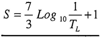
 , is defined as:
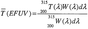
where W(λ) is the Spectral Weighting Factor given in table A1 of annex A.
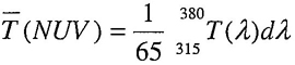
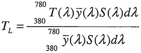
where  is the relative luminous efficiency function and S(λ) is the relative spectral emittance of Illuminant A as defined by the CIE. These functions are given in table A2 of annex A.
 , is defined as:
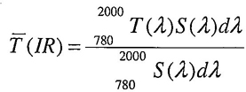
where, in the infrared, the relative spectral emittance S(λ) of Illuminant A is that of a full (“Black-body”) radiator at temperature 2856 K and is given in table A3 of annex A.
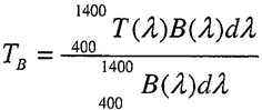
where B(λ) is the Blue-Light Hazard Function defined in table A4 of annex A.
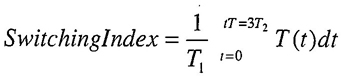
where: t = 0 is the time at which the are ignites, T1 is the designated light state, T2 is the designated dark state, t[T=3T2] is the time at which the luminous transmittance falls to three times the luminous transmittance in the dark state.
Note: In the case of short term exposure to light, the glare is approximately proportional to the product of the illuminance at the eye and time. The time dependence of the darkening process can differ for different designs of filters where the luminous transmittance varies with time. It is therefore appropriate to define the response time of an automatic darkening filter lens as an integral of the luminous transmittance over time and not merely by the initial and final luminous transmittance.
38Requirements for transmittance are given in tables 1 and 2 and the notes which immediately follow each table.
39| Shade Number | Luminous Transmittance | Maximum Effective Far-Ultraviolet Average Transmittance % |
Maximum Infrared Average Transmittance % |
||
|---|---|---|---|---|---|
| Maximum % |
Nominal % |
Minimum % |
|||
| CLEAR | 100 | - | 85 | - | - |
| 1.3 | 85 | 74.5 | 67 | 0.1 | <30 |
| 1.5 | 67 | 61.5 | 55 | 0.1 | 25 |
| 1.7 | 55 | 50.1 | 43 | 0.1 | 20 |
| 2.0 | 43 | 37.3 | 29 | 0.1 | 15 |
| 2.5 | 29 | 22.8 | 18.0 | 0.1 | 12 |
| 3.0 | 18.0 | 13.9 | 8.50 | 0.07 | 9.0 |
| 4 | 8.50 | 5.18 | 3.16 | 0.04 | 5.0 |
| 5 | 3.16 | 1.93 | 1.18 | 0.02 | 2.5 |
| 6 | 1.18 | 0.72 | 0.44 | 0.01 | 1.5 |
| 7 | 0.44 | 0.27 | 0.164 | 0.007 | 1.3 |
| 8 | 0.164 | 0.100 | 0.061 | 0.004 | 1.0 |
| 9 | 0.061 | 0.037 | 0.023 | 0.002 | 0.8 |
| 10 | 0.023 | 0.0139 | 0.0085 | 0.001 | 0.6 |
| 11 | 0.0085 | 0.0052 | 0.0032 | 0.0007 | 0.5 |
| 12 | 0.0032 | 0.0019 | 0.0012 | 0.0004 | 0.5 |
| 13 | 0.0012 | 0.00072 | 0.00044 | 0.0002 | 0.4 |
| 14 | 0.00027 | 0.00016 | 0.0001 | 0.3 | |
| 0.00044 | |||||
Notes:
| LUMINOUS TRANSMITTANCE | |||
|---|---|---|---|
| LENS TYPE | %MAXIMUM | %MINIMUM | *RATIO [R] of measured Luminous Transmittance |
| Tinted | 100 | 8 | 0.90≤ R ≤1.10 |
| Extra Dark | <8 | 0.2 | 0.8.≤ R ≤ 1.20 |
| *R is the ratio of the two measured transmittances, one for each lens of a pair, or at points directly in front of each eye for a single lens. | |||
Lenses meeting table 2 requirements may not provide UV or IR protection and wearers could be exposed to potentially harmful levels of radiation. Due to the filtering nature of tinted lenses, wearers could be exposed to increased levels of UV and IR radiation due to pupillary dilation.
Wearers should be cautioned that tinted lenses are typically designed for use for specific visual tasks. Care should be used in their selection and use, especially where color recognition is important, i.e. traffic signals, electrical wire splicing, visual displays, etc. Some tinted lenses can alter color perception.
| LIGHT SHADE NUMBER | |||||||
|---|---|---|---|---|---|---|---|
| 1.7 | 2 | 2.5 | 3 | 4 | 5 | 6 | |
| DARK SHADE NUMBER | Switching | Index (ms) |
|||||
| 7 | 300 | 400 | 500 | 700 | 1000 | - | - |
| 8 | 100 | 150 | 200 | 300 | 500 | 1000 | - |
| 9 | 40 | 50 | 70 | 100 | 200 | 400 | 700 |
| 10 | 20 | 20 | 30 | 40 | 70 | 100 | 300 |
| 11 | 6 | 7 | 10 | 15 | 30 | 50 | 100 |
| 12 | 2 | 3 | 4 | 5 | 10 | 20 | 40 |
| 13 | 0.8 | 1 | 1.5 | 2 | 4 | 7 | 10 |
| 14 | 0.3 | 0.4 | 0.5 | 0.7 | 1 | 3 | 5 |
Eye and face protection shall be required where there is a reasonable probability of injury that can be prevented by such equipment. In such cases, employers and educational authorities shall make conveniently available a protective device for the work environment, per applicable federal and state regulations. Employees and students shall use such device.
Annex I contains a Selection Chart, which will be helpful in deciding types of protective devices that are available, their capabilities and limitations. It should be recognized that dusty or chemical environments, or both might represent an additional hazard to contact lens wearers. Wearers of contact lenses shall be required to wear appropriate eye and face protection devices in a hazardous environment.
Employers and educational authorities shall provide employees and students with all warnings, cautions, instructions and limitations provided with the protector by the manufacturer and inform wearers as to their meaning.
Employees and students shall make a visual inspection of their protector prior to each use. Protective devices, which exhibit broken parts, distortion, or excessive scratches on the lens, are unsuitable for use and shall not be worn. Eye and face protective devices that have been subject to an impact shall not be used and shall be discarded.
Protectors shall be maintained in a usable condition in accordance with the manufacturers instructions.
When one protector is being used by more than one person, it is recommended that it be cleaned and disinfected prior to use by another person.
Reasonable care shall be taken during the use and storage of protectors so that are not subject to unnecessary abuse.
Employers and educational authorities shall train employees and students in the proper use, application, inspection, maintenance, storage, and limitations of protective devices.
Unless otherwise specified, all tests shall be performed at normal laboratory ambient conditions. In many tests the Alderson 50th percentile male headform is specified; if, however, a product is designed to fit a larger or smaller group of the population, then the Alderson 95th percentile male or 5th percentile female headforms should be used. Appropriate eye and face protection shall be worn for all impact and penetration tests.
Impact test methods are all type tests except for drop ball tests for non-plano spectacle lenses (section 14.4.2.1) (see 7.3.1). The frequency of repeating the type tests should be in conformance to the manufacturer's quality assurance protocol.
Statistical sampling is an acceptable means of demonstrating compliance with the performance criteria of sections 7 through 11. This standard does not require the use of a specific sampling plan, however, the plan chosen must be statistically significant. An example of an acceptable plan is ANSI/AQC Z1.4-1993.
Alternative test methods and apparatus to those cited in this standard may be used if equivalent results can be demonstrated. In case of dispute, the methods and apparatus cited in this standard shall take precedence.
4214.1.1 Purpose
This test is intended to determine the capability of a protector to resist impact from relatively heavy, pointed objects traveling at low velocity.
14.1.2 Apparatus
An Alderson 50th percentile male headform shall be used to hold the protective device. It shall be rigidly mounted in the horizontal position, face up, on a base which has a mass of 30 kg (66 lb) or greater. The static stiffness of the headform shall be such that when a vertical downward force of 20 kg (44 lb) is applied to the forehead of the headform, the back of the headform shall not deflect more than 2 mm (0.08 in). The missile shall be made of steel and shall have a 30° conical tip with a 1 mm (0.04 in) spherical radius, shall weigh 500 g (17.6 oz), and have a diameter of 25.4 mm (1.0 in), as shown in figure C4. The missile will be held in position over the headform, tip down, at the designated test height. The missile may have a hardened steel tip. Care shall be taken to maintain the tip configuration and weight of the missile.
The missile shall be dropped through a loose-fitting guide tube having a smooth internal diameter; this prevents missile tumble while not retarding free fall. Shielding around the headform is required to protect the operator.
14.1.3 Procedure
The protective device is placed on the headform as it was designed to be worn. The alignment shall be such that when the missile is dropped, its point is in line with the center of either of the eyes of the headform.
The missile shall be dropped from a height of 127 cm (50.0 in) measured from the conical tip of the missile to the impact point of the protector. To protect the operator, the guide tube shall be positioned so that the lower end of the tube is 180 mm (7.1 in) from the point of impact. Four devices shall be tested, two on the left viewing area and two on the right viewing area.
14.1.4 Analysis of Results
Failure criteria are given in sections 7 through 11 for the particular type of device being tested. Examine the device for evidence of pieces missing from the inner surface of the device. Examine the lens(es) closest to the eye for evidence of fracture, or displacement from the frame. If any of the criteria are not met, then the device fails.
14.2.1 Purpose
This test is intended to determine the capability of a protector to resist impact from high velocity, low mass projectiles.
14.2.2 Apparatus
The test apparatus shall consist of an Alderson 50th percentile male headform mounted vertically within an enclosure and a device capable of propelling a 6.35 mm (0.25 in) steel ball weighing 1.06 g (0.037 oz) reproducibly at velocities from 45.7 to 91.4 m/s (150 to 300 ft/s) at the headform. The path of the projectile shall be on a horizontal reference plane formed by the center of the eyes of the headform.
The headform shall be capable of being rotated about the vertical axis specified in 14.2.3 in 15° increments, from a first position 15° to the nasal side of straight-ahead-viewing out to 90° temporally. The headform shall be capable of being raised 10 mm (0.394 in) and lowered 10 mm (0.394 in) with respect to the horizontal reference plane to carry out testing at the 90° angular position. Mass of the test headform shall be at least 4 kg (8.8 lb).
The velocity of the steel ball shall be determined at a distance not greater than 25 cm (9.8 in) from the eye of the headform and shall have a standard deviation not exceeding 2% of the
43specified test velocity over a test series of 30 shots.
Some form of containment shall surround the headform to prevent debris or the ricocheting projectile from endangering observers. Steel balls traveling at high speeds can be lethal. Therefore, they shall be contained within the test apparatus by appropriate engineering controls to prevent injury or death.
Information about a typical High Velocity Impact Test Apparatus is given in annexes C and E.
14.2.3 Procedure
Apply a thin layer of white contact paste to each of the eyes of the headform covering an area 25mm (1.0 in) in diameter centered on the corneal vertex of the eye. The protective device shall be mounted on the headform in the manner in which the device was designed to be worn. The headform shall be adjusted so that the path of the projectile passes through the center of the anterior surface of either of the eyes of the headform. The headform is then rotated on an axis, which passes vertically at their intersection of a sagittal plane through the center of the front surface of the tested eye and a coronal (frontal) plane which is 10 mm posterior to the corneal plane which is tangent to the anterior surfaces of the eyes of the headform, to the first test position, which is 15° on the nasal side. The device is impacted at the test velocity. The balls are damaged during impact and should be changed frequently to avoid impacts at unexpected locations and large variations in velocity.
A new device is then placed on the headform and impacted at 0° another is impacted at 15° temporally, and so on, until eight devices have been impacted in the horizontal plane of the center of the eyes of the headform, with each impact centered on the axis of rotation which lies 10 mm posterior to the center of the anterior surface of the test eye of the headform. At the 90° angular position, one device shall be impacted 10 mm (0.394 in) above the plane of the eyes of the headform, and another device shall be impacted 10 mm (0.394 in) below the plane of the eyes of the headform. The total group size tested about one eye is ten devices with one impact each at 15° nasal, 0°, 15°, 30°, 45°, 60°, 75° temporal, and 3 impacts 90° temporal. A similar test is then carried out about the other eye, resulting in a total of twenty devices tested.
14.2.4 Testing Spectacles Without Side Protection
When testing spectacles without side protection, one proceeds as in 14.2.3 until reaching the angle where the lens or front is no longer impacted. Starting back at the 15° nasal position on the same side, additional samples should be tested at 15° nasal, 0°, 15° temporal. A similar procedure is then carried out on the other side of the headform.
14.2.5 Analysis of Results
Failure criteria are given in sections 7 through 11, excluding non-plano high impact lenses, which are covered by Section 14.3, for the particular type of device being tested. Examine the headform for pieces of the protector adhering to the contact paste. Examine the device for evidence of pieces missing from the inner surface of the device. Examine the protector and the ball for any contact paste. Adherence of pieces to the contact paste or contact paste on the ball or protector is evidence of a failure. Examine the lens(es) closest to the eye for evidence of fracture. If any fail, the device fails.
Plano power lenses, maximum base curve of 6.25, shall be edged round with an industrial safety bevel to a diameter 55.0 mm +0.04 mm/-0.25 mm. Each lens shall be tested once, with a new lens used for each additional impact. Each lens shall be mounted in the test holder (see figure B3) by two retaining washers so that the test lens is held firmly against the bevel of the
44lens holder. Perform the high velocity impact test on the center of each lens with the missile specified in 14.2 at a velocity of 45.7 m/s (150 ft/sec.).
Repeat the test with 2 additional sample lenses, giving a total of three test lenses. Failure consists of any posterior displacement of the lens completely through the test holder; any fracture of the lens; any detachment of a portion of the lens from its inner surface; or any full thickness penetration of a lens. Failure of any lens constitutes a failure. If all test lenses pass, then any prescription lens of the same or greater thickness at its thinnest point, which is made by the same manufacturer, from the same material, with the same coatings and processes may bear the “+” mark.
14.4.1 Purpose
These tests are intended to ensure that various types of lenses posses levels of impact resistance equal to those meeting requirements of the previous ANSIZ87.1 standard when tested with the traditional drop-ball impactor.
14.4.2 Test Sample Sizes
Four devices shall be tested except for non-plano spectacle lenses, (see Section 7.3.1).
14.4.2.1 Removable Spectacle Lenses
For testing removable spectacle lenses, the lens shall be removed from the frame and placed mechanically centered, convex side up, on the test block of an anvil composed of the parts shown in figure B1, mounted in the hole of the base plate shown in figure B2, the whole assembly on a flat, horizontal work surface of convenient height. A 25.4 mm (1 in) diameter steel ball, weighing 68 g (2.4 oz), shall be dropped in free fall from a height of 127 cm (50 in) onto the horizontal outer surface of the lens, perpendicularly impinging on the lens within a circular area of 16 mm (0.63 in) diameter centered at the lens mechanical center.
14.4.2.2 Round, Removable Goggle Lenses
For testing round, removable goggle lenses, the lens shall be removed from the eyecup and placed flat on the end of a wooden tube having an internal diameter of 45mm (1.77 in) and a rim to fit the lens. A washer of neoprene rubber of a 40+/−5 durometer Shore A reading, not more than 3.2 mm (1/8 in) thick, and of the same size as the end diameter of the tube, shall be placed between the lens and the tube. A steel ball shall be freely dropped from a height of 127 cm (50 in) onto the horizontal outer surface of the lens. Clear lenses and filter lenses with shade numbers up to and including shade 3 shall be tested with a 25.4 mm (1.0 in) diameter steel ball weighing 68 g (2.4 oz). Filter lenses of shades higher than 3 shall be tested with a 22 mm (7/8 in) diameter steel ball weighing 44.2 g (1.56 oz).
14.4.2.3 Rectangular, Removable Goggle and Welding Helmet Lenses
For testing removable, rectangular goggle and welding helmet lenses, a suitable rigid frame not less than 20 mm (0.81 in) in height is required. The support frame shall provide a 6.4 mm (0.25 in) support around the periphery of the lens to be tested. A washer of neoprene rubber of a 40+/−5 durometer Shore A reading, not more than 3.2 mm (0.125 in) thick, and of the same internal dimensions as the supporting surface, shall be placed between the lens and the support.
For rectangular goggle lenses, a 22 mm (7/8 in) diameter steel ball weighing 44.2 g (1.56 oz) shall be freely dropped from a height of 1.0 m (39 in) onto the center of the horizontal outer surface of the lens.
For welding helmets, a 15.9 mm (5/8 in) diameter steel ball weighing 16 g (0.56 oz) shall be freely dropped from a height of 1.0 m (39 in) onto the center of the horizontal surface of the lens. For welding helmet clear lenses (not cover lenses, see 10.13), a 25.44 mm (1 in) diameter steel ball weighing 68 g (2.4 oz) shall be freely
45dropped from a height of 127 cm (50 in) onto the center of the horizontal outer surface of the lens.
14.4.2.4 Removable Faceshield Lens
A faceshield with the removable lens shall be put on an Alderson 50th percentile male headform as described in section 14.1.2. An additional supporting block, approximately 25.4 mm (1.0 in) wide and curved to conform to the shape of the faceshield shall be provided as a support for the faceshield at its lower end but not lower than the chin of the headform. The headform is positioned so that the axis of the faceshield is horizontal and the outer surface of the window is facing upward. A 25.4 mm (1 in) diameter steel ball, weighing 68 g (2.4 oz) shall be freely dropped from a height of 127 cm (50 in) into the apex of the window at a point in line with the eyes of the headform.
14.4.2.5 Other Devices
For testing all other devices, and Alderson 50th percentile male headform as described in section 14.1.2 is required.
For all devices with non-removable lenses, the device shall be placed on the headform of the High Mass Impact Test Apparatus (Section 14.1) as it would be worn by the user. The alignment shall be such that when the ball is dropped, it is in line with either of the eyes of the headform.
14.4.3 Analysis of Results
Failure criteria are given in Sections 7 through 11 for the particular type of device being tested. Examine the device for evidence of fracture or penetration. The device fails if any evidence of fracture or penetration is seen.
14.5.1 Purpose
This test is intended to determine the capability of a plastic lens to resist penetration by a low mass pointed projectile.
14.5.2 Apparatus
The test apparatus shall consist of a pointed projectile consisting of a new 135 x 17 needle fastened into a holder, weighing 44.2 g (1.56 oz). The projectile shall be dropped through a loose-fitting guide tube having a smooth internal diameter; this prevents projectile tumble while not retarding free fall.
For testing removable spectacle lenses, a test block, as shown in figure B1, mounted in the hole of a base plate, as shown in figure B2, is required.
For testing removable goggle and welding helmet lenses, a rigid frame not less than 20 mm (0.81 in) in height is required. The support frame shall provide a 6.4 mm (0.25 in) support around the periphery of the lens to be tested. A washer of neoprene rubber of a 40+/−5 durometer Shore A reading, not more than 3.2 mm (0.125 in) thick, and of the same internal dimensions as the support, shall be placed between the lens and the support.
For testing all other devices an Alderson 50th percentile male headform as described in section 14.1.2 is required. For faceshields, an additional supporting block, approximately 25.4 mm (1.0 in) wide and curved to conform to the shape of the window, shall be provided as a support for the window at its lower end but not lower than the chin of the headform.
14.5.3 Procedure
The projectile shall be freely dropped through the guide tube, point downward, from a height of 127 cm (50 in) onto the horizontal outer surface of the lens. Four devices shall be tested. To protect the operator, the guide tube shall be positioned so that the lower end of the tube is 102 mm (4.0 in) from the point of impact.
46For removable lenses, the lens shall be removed from the frame and placed mechanically centered, convex side up, on the test block as described in section 14.4.2.
For faceshields, the window shall be placed in a horizontal position such that the axis of the window is horizontal and the outer surface of the window is facing upward. The projectile shall be dropped onto the apex of the window at a point in line with the eyes of the headform.
For all devices with non-removable lenses, the device shall be placed on the headform of the High Mass Impact Test Apparatus (Section 14.1) as it would be worn by the user. The alignment shall be such that when the projectile is dropped, its point is in line with either of the eyes of the headform.
14.5.4 Analysis of Results
Failure criteria are given in sections 7 through 11, for the particular type of device being tested. Examine the device for evidence of fracture or penetration. The device fails if any evidence of fracture or penetration is seen.
14.6.1 Purpose
This test is intended to measure the rate of burning or extent of burning of plastics used in protectors.
14.6.2 Apparatus and Procedure
The apparatus and procedure as specified in ASTM test method D635-1998 shall be used to evaluate the flammability of plastic components. Alternatively, certification of the materials used provided by the source of supply is acceptable.
14.6.3 Analysis of Results
Failure criteria are given in sections 7 through 11 for the particular type of device being tested.
14.7.1 Purpose
This test is intended to determine the capability of metal components of a protector to resist corrosion.
14.7.2 Apparatus
The test apparatus shall consist of a boiling saline solution and a room temperature saline solution both in containers of sufficient dimensions to submerse the metal parts. The saline solutions shall contain 10% by weight of sodium chloride in water.
14.7.3 Procedure
Metal parts shall be submersed in the boiling saline solution for a period of fifteen minutes. The parts, upon being removed from the boiling solution, shall be immediately immersed in the room temperature saline solution. They shall then be removed from this solution, and without having the adhering liquid wiped off, allowed to dry for twenty-four hours at room temperature. The metal parts shall then be rinsed in lukewarm water and allowed to dry.
14.7.4 Analysis of Results
Failure criteria are given in sections 7 through 11 for the particular type of device being tested. Examine the device for functional impairment.
14.8.1 Purpose
This test is intended to determine the capability of a protector to withstand cleaning.
14.8.2 Apparatus and Procedure
Products shall be cleaned in accordance with the manufacturer's instructions. If none are available, clean with mild soap and warm water solution by soaking the device in the soap solution maintained at 43°C-49°C (110 - 120°F)
47for ten minutes. Rinse thoroughly and allow to air dry.
14.8.3 Analysis of Results
Failure criteria are given in sections 7 through 11 for the particular type of device being tested. Examine the device following the test cleaning process for functional impairment.
14.9.1 Purpose
This test is intended to measure the prismatic power and prismatic imbalance of a protector.
14.9.2 Apparatus
This apparatus shall consist of an Alderson 50th percentile male headform which has been modified by boring two through holes at least 19.0 mm (0.75 in) diameter centered on each eye. The headform shall be placed in an optical system as shown in figure C6. The telescope lens, L2, shall be located at a distance of 1.0 m (39.4 in) in front of image plane, IP. The pinhole aperture plate, p, shall be located approximately 1.0 m (39.4 in) from the collimator lens, L1, and shall be adjusted so that one image is formed on the image plane, IP, when no protector is on the headform. The position of that image shall be marked or noted and will be called Po.
14.9.3 Procedure
The protective device shall be placed on the headform in the designed wearing position, without having changed the spacing of the optical system. The image(s) on the image plane shall be identified as coming from the right eye, Pr, or the left eye, PI, by blocking the beams of each eye. The distance in centimeters between the centers of P1 and Po and Pr and Po shall be measured. The prismatic power of the protector in prism diopters (Δ) is determined by measuring the distance in centimeters between Po and P1 or Po and Pr, whichever is greater.
The horizontal and vertical distances in centimeters between the centers of PI and Pr shall be measured.
The horizontal prism imbalance of the protector in prism diopters shall be the horizontal distance measured in centimeters between PI and Pr. The vertical prism imbalance of the protector in prism diopters shall be the vertical distance measured in centimeters between PI and Pr. The “base” of the horizontal prism imbalance shall be determined by looking at the image plane (looking at the image plane from the headform). If the right-most image comes from the right eye of the headform, then the prism imbalance is “base out”. If the left-most image comes from the right eye of the headform, then the prism imbalance is “base in”.
14.9.4 Analysis of Results
Failure criteria are given in sections 7 through 11 for the particular type of device being tested.
14.10.1 Purpose
These tests are intended to determine that the protectors meet the optical requirements for refractive power, astigmatism and resolving power of this standard.
14.10.2 Apparatus
The apparatus shall consist of a calibrated 8 power telescope having a minimum aperture of 19 mm, a means of holding the protector in the test position, a sunburst test pattern, figure C5, and a high contrast test pattern from NBS Special Publication 374, (See annex E for source). The test patterns shall be interchangeable and mounted 10.67 m (35 ft) from the objective lens of the telescope. Calibration methods for the telescope are given in annex D.
4814.10.3 Procedure
The telescope and observer shall be qualified by resolving pattern 40 of the high contrast test pattern when no lens is in front of the telescope. The telescope shall then be focused on the sunburst test pattern (See Annex C). The lens to be tested shall be positioned with the primary line of sight coincident with the axis of the telescope.
The distance between the lens being tested and the objective lens of the telescope shall not exceed 38 mm (1.5 in). The telescope is then refocused on the radial lines until they appear as sharp as possible. Two possibilities may then occur, all or just some of the lines will appear well focused.
If all radial lines appear equally well-focused at the same position of the focus wheel, the lens had no measurable astigmatism and the power reading of the telescope is the refractive power of the test lens.
If lines in only one meridian appear sharpest at a given focus, then the telescope shall be refocused to determine the best focus for the lines in the meridian which yield an extreme (maximum or minimum) power reading. The power reading shall be noted. The telescope shall be then re-focused for lines in the meridian which yields the opposite extreme power reading. The second power reading shall be noted. The astigmatism shall be calculated as the absolute value of the algebraic difference between the two extreme power readings.
The telescope shall then be re-focused for the best compromise focus, that is, until all radial lines appear equally sharp. The sunburst test pattern shall be replaced with the high contrast test pattern. The observer shall attempt to resolve all lines of pattern 20 in both orientations without re-focusing the telescope.
14.10.4 Analysis of Results
Failure criteria are given in sections 7 through 11 for the particular type of device being tested.
14.11.1 Purpose
This test is intended to measure the haze in clear lenses.
14.11.2 Apparatus and Procedure
The apparatus and procedures specified in ASTM D1003-00, Test Method for Haze and Luminous Transmittance of Transparent Plastics, shall be used to measure the haze. The illuminant used shall be CIE illuminant A.
14.11.3 Analysis of Results
Failure criteria are given in sections 7 through 11 for the particular type of device being tested.
14.12.1 Purpose
This test is intended to measure the ultraviolet, luminous, infrared and blue-light, normal transmittance of lenses.
14.12.2 Transmittance
The transmittance may be determined by any suitable method, but the reference method shall be the use of a spectrophotometer and calculation using appropriate weighting factors given in tables A1 through A4 of annex A.
14.12.3 Analysis of Results
Criteria for ultraviolet, luminous, infrared and blue-light, normal transmittance are given in sections 7 through 10 for the particular type of device being tested.
14.13.1 Purpose
This test is intended to determine the switching index of an automatic darkening filter lens which requires the measurement of luminous
49transmittance over time as the device is exposed to optical radiation from a test light source.
14.13.2 Apparatus
The following test apparatus, or an equivalent apparatus capable of determining compliance with table 3, shall be used. The response time of the test apparatus (between 10% and 90% of recorded peak light intensity) shall be no greater than 10% of the required switching index of the lens under test. The test apparatus shall consist of a light source, detector, trigger light source and a recording device.
The light source shall be a high intensity collimated light source which, when optically coupled to an associated light detector, provides the required intensity to measure the luminous transmittance of the lens under test in its highest shade number state.
The detector shall have a calibrated photopic response, which, when coupled with an associated light source, is capable of measuring the luminous transmittance of the lens under test in its highest shade number state.
The trigger light source shall be a high intensity light source of at least 10,000 lux capable of being either electronically or mechanically switched on.
The recording device shall be a storage oscilloscope or equivalent device capable of recording the output of the detector, in time, and providing output functions of normal transmittance and time.
14.13.3 Procedure
The test specimen (automatic darkening welding filter) shall be maintained at the appropriate test temperature for a minimum of 2 hours before testing and during the period of test. Ambient lighting conditions during testing shall not exceed 16 lux.
The test specimen and light detectors shall be mounted normal to the beam of illumination. Solar or photoelectric power cells shall be shielded from the transmittance light source beam.
Methods shall be employed to ensure that the temperature of the lens under test does not exceed the prescribed test temperature (For example: due to exposure from the transmittance light source).
With the transmittance light source activated, the trigger light source shall be switched to its high illumination state. The luminance variations over time, of the triggering light source at the filter and the transmittance light source through the filter, shall be recorded.
14.13.4 Analysis of Results
The switching index shall be calculated from the integral given in section 12.1 equation 7, taking t=0 as the time when recorded illuminance reaches 5000 lux. Failure criteria are given in section 10.12.4 and 10.12.5.
14.14.1 Purpose
This test is to determine that welding helmets have light sealing capabilities between the lens and the lens holder.
14.14.2 Apparatus
The apparatus shall consist of a device capable of illuminating the entire lens retaining area and confining the light to the exterior surface of the helmet. An example is shown in Figure C3. A shade 14 lens shall be used to test for light leakage. Automatic darkening filter lenses shall be tested with the viewing area covered with an opaque material.
5014.14.3 Procedure
The welding helmet shall be held firmly against the seal of the test apparatus and examined for direct light leakage between the lenses, gaskets or other components. The test shall be performed in a darkened room to verify a light tight design when viewed from any angle.
14.14.4 Analysis of Results
Failure criteria are given in section 10.9.2.
Warning shall be provided to alert the user when the lens(es) of a protector meets only the basic impact requirements of this standard.
A clearly visible, removable label or hang tag shall be affixed to any protector which does not meet the high impact requirements of this standard. The label or tag shall contain an appropriate warning indicating that the lens meets basic impact requirements, but should not be relied upon for protection from high impact exposures. The label or tag shall also state that it is to be removed only by the user.
51| Wavelength (nm) |
Spectral Weighting Factor W(λ) |
|---|---|
| 200 | 0.03 |
| 210 | 0.075 |
| 220 | 0.12 |
| 230 | 0.19 |
| 240 | 0.30 |
| 250 | 0.43 |
| 254 | 0.5 |
| 260 | 0.65 |
| 270 | 1.0 |
| 280 | 0.88 |
| 290 | 0.64 |
| 300 | 0.30 |
| 305 | 0.06 |
| 310 | 0.015 |
| 315 | 0.003 |
| NOTE: This table is a reproduction of Table 10 “Relative Spectral Effectiveness by Wavelength,” from Threshold Limit Values for Chemical Substances and Physical Agents in the Work Environment with Intended Changes for 1982. Published by the American Conference of Governmental Industrial Hygienists. | |
| λ(nm) |  |
S(λ) |
|---|---|---|
| 380 | 0.0000 | 9.80 |
| 385 | 0.0001 | 10.90 |
| 390 | 0.0001 | 12.09 |
| 395 | 0.0002 | 13.35 |
| 400 | 0.0004 | 14.71 |
| 405 | 0.0006 | 16.15 |
| 410 | 0.0012 | 17.68 |
| 415 | 0.0022 | 19.29 |
| 420 | 0.0040 | 20.99 |
| 425 | 0.0073 | 22.79 |
| 430 | 0.0116 | 24.67 |
| 435 | 0.0168 | 26.64 |
| 440 | 0.0230 | 28.70 |
| 445 | 0.0298 | 30.85 |
| 450 | 0.0380 | 33.09 |
| 455 | 0.0480 | 35.41 |
| 460 | 0.0600 | 37.81 |
| 465 | 0.0739 | 40.30 |
| 470 | 0.0910 | 42.87 |
| 475 | 0.1126 | 45.52 |
| 480 | 0.1390 | 48.24 |
| 485 | 0.1693 | 51.04 |
| 490 | 0.2080 | 53.91 |
| 495 | 0.2586 | 56.85 |
| 500 | 0.3230 | 59.86 |
| 505 | 0.4073 | 62.93 |
| 510 | 0.5030 | 66.06 |
| 515 | 0.6082 | 69.25 |
| 520 | 0.7100 | 72.50 |
| 525 | 0.7932 | 75.79 |
| 530 | 0.8620 | 79.13 |
| 535 | 0.9149 | 82.52 |
| 540 | 0.9540 | 85.95 |
| 545 | 0.9803 | 89.41 |
| 550 | 0.9950 | 92.91 |
| 555 | 1.0000 | 96.44 |
| 560 | 0.9950 | 100.00 |
| 565 | 0.9786 | 103.58 |
| 570 | 0.9520 | 107.18 |
| 575 | 0.9154 | 110.80 |
| 580 | 0.8700 | 114.44 |
| 585 | 0.8163 | 118.08 |
| 590 | 0.7570 | 121.73 |
| 595 | 0.6949 | 125.39 |
| 600 | 0.6310 | 129.04 |
| 605 | 0.5668 | 132.70 |
| 610 | 0.5030 | 136.35 |
| 615 | 0.4412 | 139.99 |
| 620 | 0.3810 | 143.62 |
| 625 | 0.3210 | 147.24 |
| 630 | 0.2650 | 150.84 |
| 635 | 0.2170 | 154.42 |
| 640 | 0.1750 | 157.98 |
| 645 | 0.1382 | 161.52 |
| 650 | 0.1070 | 165.03 |
| 655 | 0.0816 | 168.51 |
| 660 | 0.0610 | 171.96 |
| 665 | 0.0446 | 175.38 |
| 670 | 0.0320 | 178.77 |
| 675 | 0.0232 | 182.12 |
| 680 | 0.0170 | 185.43 |
| 685 | 0.0119 | 188.70 |
| 690 | 0.0082 | 191.93 |
| 695 | 0.0057 | 195.12 |
| 700 | 0.0041 | 198.26 |
| 705 | 0.0029 | 201.36 |
| 710 | 0.0021 | 204.41 |
| 715 | 0.0015 | 207.41 |
| 720 | 0.0010 | 210.36 |
| 725 | 0.0007 | 213.27 |
| 730 | 0.0005 | 216.12 |
| 735 | 0.0004 | 218.92 |
| 740 | 0.0002 | 221.67 |
| 745 | 0.0002 | 224.36 |
| 750 | 0.0001 | 227.00 |
| 755 | 0.0001 | 229.59 |
| 760 | 0.0001 | 232.12 |
| λ | S(λ) | λ | S(λ) | λ | S(λ) | λ | S(λ) | λ | S(λ) | λ | S(λ) |
|---|---|---|---|---|---|---|---|---|---|---|---|
| 700 | 198.26 | 1050 | 298.78 | 1400 | 232.72 | 1750 | 161.42 | 2100 | 108.81 | 2450 | 73.94 |
| 710 | 204.41 | 1060 | 289.28 | 1410 | 230.56 | 1760 | 159.63 | 2110 | 107.60 | 2460 | 73.15 |
| 720 | 210.36 | 1070 | 288.66 | 1420 | 228.40 | 1770 | 157.86 | 2120 | 106.40 | 2470 | 72.37 |
| 730 | 216.12 | 1080 | 287.94 | 1430 | 226.23 | 1780 | 156.10 | 2130 | 105.21 | 2480 | 71.60 |
| 740 | 221.67 | 1090 | 287.12 | 1440 | 224.06 | 1790 | 154.37 | 2140 | 104.04 | 2490 | 70.83 |
| 750 | 227.00 | 1100 | 286.20 | 1450 | 221.90 | 1800 | 152.65 | 2150 | 102.88 | 2500 | 70.08 |
| 760 | 232.12 | 1110 | 285.18 | 1460 | 219.74 | 1810 | 150.94 | 2160 | 101.73 | 2510 | 69.33 |
| 770 | 237.01 | 1120 | 284.08 | 1470 | 217.58 | 1820 | 149.25 | 2170 | 100.60 | 2520 | 68.60 |
| 780 | 241.68 | 1130 | 282.90 | 1480 | 215.42 | 1830 | 147.59 | 2180 | 99.48 | 2530 | 67.87 |
| 790 | 246.12 | 1140 | 281.64 | 1490 | 213.27 | 1840 | 145.93 | 2190 | 98.38 | 2540 | 67.15 |
| 800 | 250.83 | 1150 | 280.30 | 1500 | 211.13 | 1850 | 144.30 | 2200 | 97.29 | 2550 | 66.44 |
| 810 | 254.31 | 1160 | 278.89 | 1510 | 209.00 | 1860 | 142.68 | 2210 | 96.21 | 2560 | 65.74 |
| 820 | 258.07 | 1170 | 277.42 | 1520 | 206.87 | 1870 | 141.08 | 2220 | 95.14 | 2570 | 65.05 |
| 830 | 261.60 | 1180 | 275.89 | 1530 | 204.75 | 1880 | 139.50 | 2230 | 94.09 | 2580 | 64.37 |
| 840 | 264.91 | 1190 | 274.29 | 1540 | 202.64 | 1890 | 137.93 | 2240 | 93.05 | 2590 | 63.69 |
| 850 | 267.99 | 1200 | 272.64 | 1550 | 200.54 | 1900 | 136.38 | 2250 | 92.03 | 2600 | 63.02 |
| 860 | 270.86 | 1210 | 270.94 | 1560 | 198.45 | 1910 | 134.85 | 2260 | 91.01 | ||
| 870 | 273.51 | 1220 | 269.20 | 1570 | 196.38 | 1920 | 133.33 | 2270 | 90.01 | ||
| 880 | 275.95 | 1230 | 267.40 | 1580 | 194.31 | 1930 | 131.83 | 2280 | 89.02 | ||
| 890 | 278.18 | 1240 | 265.57 | 1590 | 192.26 | 1940 | 130.35 | 2290 | 88.05 | ||
| 900 | 280.21 | 1600 | 190.22 | 1600 | 190.22 | 1950 | 128.89 | 2300 | 87.08 | Calculate by method given in Publication CIE No. 15 (E-1.3.1) 1971 “COLORIMETRY”, p. 23, par. (b) | |
| 910 | 282.04 | 1260 | 261.79 | 1610 | 188.19 | 1960 | 127.44 | 2310 | 86.13 | ||
| 920 | 283.68 | 1270 | 259.83 | 1620 | 186.18 | 1970 | 126.00 | 2320 | 85.19 | ||
| 930 | 285.12 | 1280 | 257.88 | 1630 | 184.18 | 1980 | 124.59 | 2330 | 84.26 | ||
| 940 | 286.39 | 1290 | 255.88 | 1640 | 182.20 | 1990 | 123.19 | 2340 | 83.34 | ||
| 950 | 287.47 | 1650 | 180.23 | 1650 | 180.23 | 2000 | 121.80 | 2350 | 82.43 | Values start at 700 nm to show overlap with values in Table A2 of this appendix. | |
| 960 | 288.39 | 1310 | 251.81 | 1660 | 178.28 | 2010 | 120.43 | 2360 | 81.53 | ||
| 970 | 289.14 | 1320 | 249.74 | 1670 | 176.34 | 2020 | 119.08 | 2370 | 80.65 | ||
| 980 | 289.72 | 1330 | 247.66 | 1680 | 174.42 | 2030 | 117.74 | 2380 | 79.77 | ||
| 990 | 290.15 | 1340 | 245.56 | 1690 | 172.51 | 2040 | 116.42 | 2390 | 78.91 | ||
| 1000 | 290.43 | 1350 | 243.45 | 1700 | 170.62 | 2050 | 115.12 | 2400 | 78.06 | ||
| 1010 | 290.57 | 1360 | 241.32 | 1710 | 168.75 | 2060 | 113.83 | 2410 | 77.21 | ||
| 1020 | 290.57 | 1370 | 239.18 | 1720 | 166.89 | 2070 | 112.55 | 2420 | 76.38 | ||
| 1030 | 290.43 | 1380 | 237.04 | 1730 | 165.05 | 2080 | 111.29 | 2430 | 75.56 | ||
| 1040 | 290.17 | 1390 | 234.88 | 1740 | 163.23 | 2090 | 110.04 | 2440 | 74.75 | ||
| Wavelength (nm) |
Blue-Light hazard Factors B(λ) |
|---|---|
| 400 | .10 |
| 405 | .20 |
| 410 | .40 |
| 415 | .80 |
| 420 | .90 |
| 425 | .95 |
| 430 | .98 |
| 435 | 1.00 |
| 440 | 1.00 |
| 445 | .97 |
| 450 | .94 |
| 455 | .90 |
| 460 | .80 |
| 465 | .70 |
| 470 | .62 |
| 475 | .55 |
| 480 | .45 |
| 485 | .40 |
| 490 | .22 |
| 495 | .16 |
| 500-600 | 10 exp [(450-λ)/50] |
| 600-1400 | .001 |
| NOTE: This table is a reproduction of part of Table 12, “Spectral Weighting Functions for Assessing Retinal Hazards from Broad Optical Sources”, from Threshold Limit Values for Chemical Substances and Physical Agents in the Work Environmental with Intended Changes for 1982, Published by the American Conference of Governmental Industrial Hygiene. | |
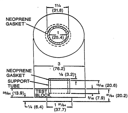
Figure B1 - Lens Test Block
NOTE: (1) One of the test blocks shown are to be inserted in the base plate described in Figure B2 of this standard. The neoprene gasket must have a hardness of 40+/-5 durometer shore A, as determined by American Society for Testing and Materials Standard Test Method for Rubber Property-Durometer Hardness, ASTM D2240-2002; a minimum tensile strength of 6895 kPa (1000 psi), as determined by American Society for Testing and Materials Standard Test Method for Rubber Properties in Tension, ASTM D 412-1998a; and a minimum ultimate elongation of 400%, as determined by ASTM D 412-1998a. The support tube made of a suitable rigid material must fit loosely in the recess in the test block, but must have an outside diameter of not less than 31.4 mm (1.234 in). The gasket must be securely bonded to the support tube. The test block must be made of (cold-rolled steel) American Iron and Steel Institute No. C1018, or the equivalent. However, if any diameter of an edged lens is less than 31.8 mm (1.25 in), a substitute support may be used whose outside diameter is equal to, or less than, the smallest diameter of the edged lens. The wall thickness of the neoprene gasket is a nominal 3.2 mm (0.125 in).

Figure B2 - Base Plate for Impact Test Apparatus
NOTES:
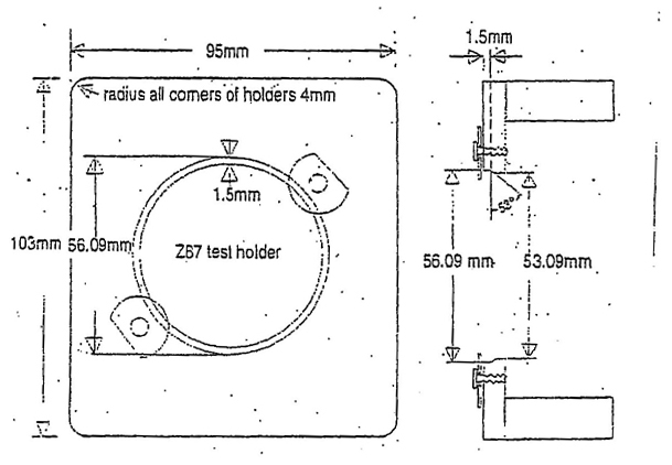
Figure B3 - Lens Fixture for Rx Lens Testing
57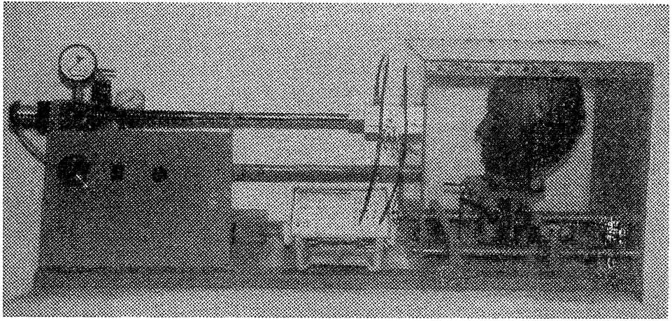
Figure C1 - High Velocity Impact Test Apparatus
(The unit shown above or its equivalent is suitable for the high velocity impact test.)
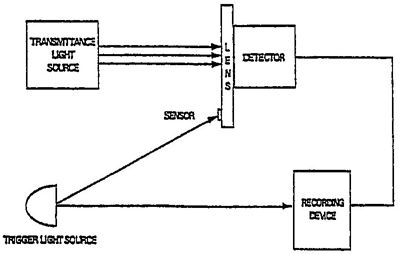
Figure C2 - Switching Index Tightness Test Apparatus
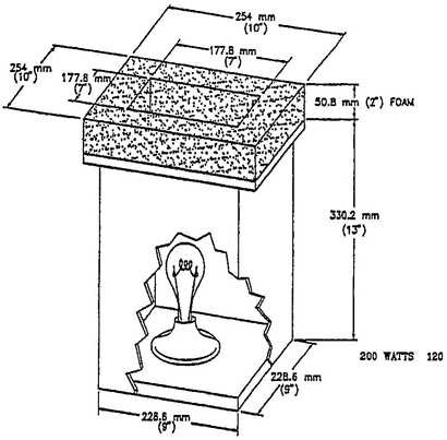
Figure C3 - Typical Light Test Set-Up Configuration
58
Figure C4
High Mass Impact Missile

Figure C5
Test Pattern “Sunburst”
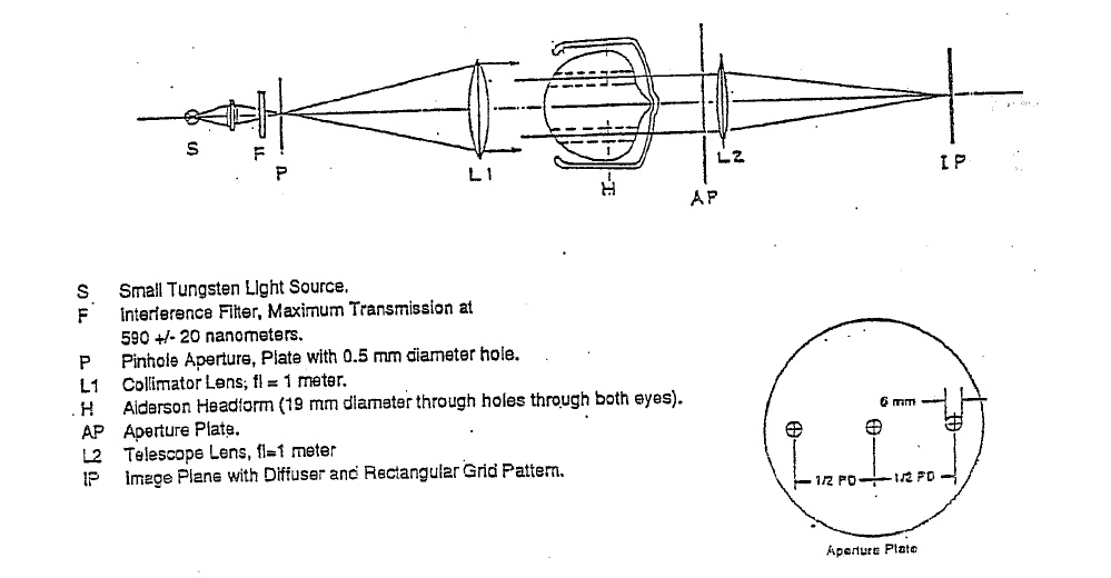
Figure C6
Prism Imbalance Test Apparatus
The telescope may be calibrated by any of the three methods given below.
(1) The telescope may be calibrated by successively locating the position of best focus with first a standard lens of +0.06 D in front of the objective and then with a standard lens of −0.06 D in front of the objective. The positions of the telescope drawtube or focusing knob, which correspond to the +/−0.06 D positions are marked on a suitable scale. The zero power position is located half the distance between the two marks. It should be verified that with no lens in front of the test telescope, the position of sharpest focus of the target is at the zero power scale position determined above. It is suggested that the scale distance between the +0.06 D position and −0.06 D position be divided into at least twenty equally spaced intervals so as to allow reasonably accurate determination of astigmatism.
(2) If effective focal length, f, of the telescope objective is measured or is known from data furnished by the telescope manufacturer, then calibration of the power scale of the telescope may be done as follows:
Since P, the power of the telescope objective, is the reciprocal of the effective focal length of the objective in meters, if a lens of lower power, such as a plano lens, is placed near the telescope objective, the combined system will have a small change in focal length which causes re-focusing of the telescope to be necessary. Since P = 1/f, then dP = −df/f and hence df = −fdP. Since the focal length of a typical test telescope is in the order of 200 mm (7.9 in) (and hence it has a power of 5 Ds), the change in focal position produced by putting an acceptable plano lens in front of a telescope is small and hence the change in focal length (change of eyepiece position for best focus) is proportional to the power of the plano lens placed in front of the objective. Having calculated, then, the scale span between the +0.06 D and −0.06 D positions, the zero position must be determined. This is best done by having several operators take a number of readings at the best focus position for the 10.67 m (35 ft) distant target when no lens is in front of the telescope objective, and then averaging those readings. Before taking the readings, each operator should focus the eyepiece first on the cross hairs to suit his individual visual requirements.
(3) Vergence of light from a target at a distance of 10.67 m is 1/10.67 = −0.09372 D, so the vergence required of the telescope is +0.09372 D to form an image of the target when no test lens is in place. If a lens of +0.065 D = −0.03122 D, which corresponds to light from a target at 1/0.03122 D = 32.03 m (105.1 ft). Similarly, if a lens of −0.06 D is used, vergence of light reaching the telescope is −0.09372 D −0.065 D = −0.15622 D, which corresponds to light from a target at 6.40 m (21 ft). Therefore, the positions of the telescope focusing knob corresponding to test lens powers of +/−0.06 D can be established by focusing the telescope at targets spaced 32.03 m (105.1 ft) and 6.40 m (21.0 ft) respectively from the telescope.
60Source for All Test Apparatus and Test Patterns:
ICS Laboratories
1072 Industrial Parkway North
Brunswick, OH 44212
(330)220-0515 FAX : (330)220-0516
Source for Alderson Headform:
First Technology Safety Systems
47460 Galleon Drive
Plymouth, MI 48170
(734)451-7878
NOTE: Order “50th percentile male ATD 3215 headform with ears modified to hold spectacles”.
Source for High Velocity Impact Test Apparatus:
Skylark Machine
Attn. Gene Dykens
60 Veterans Drive, Unit 2
Holland, MI 49423
(616)396-7906 FAX : (616)396-7940
COLTS Laboratories
Attn. John Young
21915 US 19 N.
Clearwater, FL 33765
(813)725-2323 FAX : (813)725-8890
Source for Prismatic Power Test Apparatus:
Professional Services Industries, Inc.
Pittsburgh Testing Laboratory Division
850 Poplar Street
Pittsburgh, PA 15220
(412)922-4000 FAX (412)922-4014
Source for NBS Special Publication and Sunburst Test Pattern:
ISEA - The Safety Equipment Association
1901 N. Moore Street, Suite 808
Arlington, VA 22209
(703)525-1695 FAX (703)528-2148
ANSI Z49.1-1999, American National Standard Safety in Welding and Cutting.
ANSI Z89.1-1997, American National Standard for Personnel Protection - Protective Headwear for Industrial Workers - Requirements.
ANSI Z136.1-1993, American National Standard for Safe Use of Lasers.
ANSI/ASQC Z1.4 - 1993, Sampling Procedures and Tables for Inspections by Attributes.
ASTM F803 - Standard Specification for Protective Sports Eyewear
29CFR 1910.133 - Eye and Face Protection, OSHA General Industry Standards.
29CFR1915.153 - Eye and Face Protection, OSHA Shipyard Standards.
29CFR1926.102 - Eye and Face Protection, OSHA Construction Industry Standards.
62| Required Marks | Removable Lens(es) | Removable Side Protection | Frame* | Non-Replaceable Components Products1 |
|---|---|---|---|---|
| Manufacturer's Mark | ALL | ALL | ALL | ALL |
| “Z87” | FS, G, WH | ALL | ALL | ALL |
| “Z87-2” | IF APPL2 | |||
| “+” (high impact) | IF APPL | ALL | ||
| Shade Number | IF APPL | IF APPL | ||
| “S” (special purpose) | IF APPL | IF APPL | ||
| “Light/Medium/Dark” | FS-IF APPL | FS-IF APPL | ||
| “V” (Variable tint-photochromic) | IF APPL | IF APPL |
*Frame Marking Locations on Eye and Face Protectors
| Category | Frame Components Subject to Markings |
|---|---|
| Spectacles | front, at least one temple and removable sideshields |
| Goggles | frame and lens housing or carrier |
| Faceshields | headgear/adapter and crown |
| Welding Helmets and Handshields | headgear, shell and lens housing or carrier |
1For non-replaceable component products, including products with non-removable lenses, only one product marking is required.
2Dual lens, non-plano (such as prescription) spectacle frames only.
LEGEND
| ALL= | all categories of products: spectacles, goggles, face shields and welding helmets |
| FS= | faceshields |
| G= | goggles |
| WH= | welding helmets |
| IF APPL= | if applicable (if the product complies with the appropriate requirements) |
The attached form is provided for users of occupational and educational eye and face protection. completing and returning this form will assist the Z87 Committee on Safety Standards for Eye Protection to improve this standard and develop others, as appropriate. The Eye Injury Report Form is not subject to copyright and may be reproduced as needed.
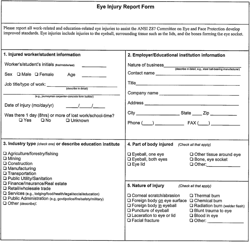
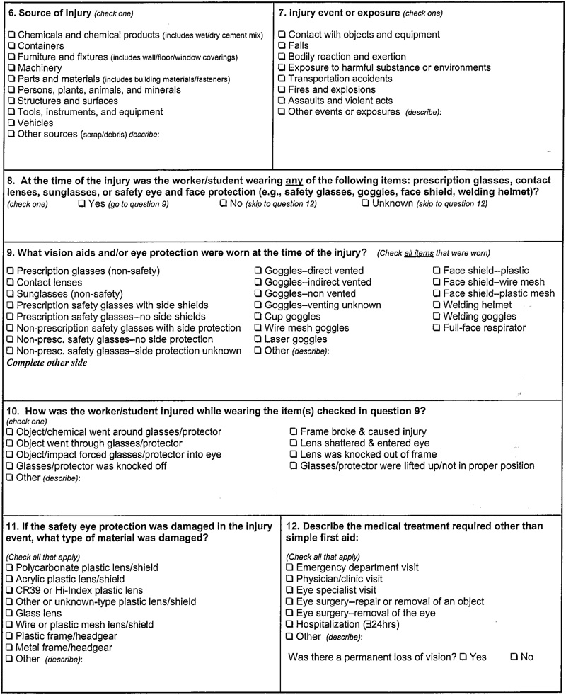
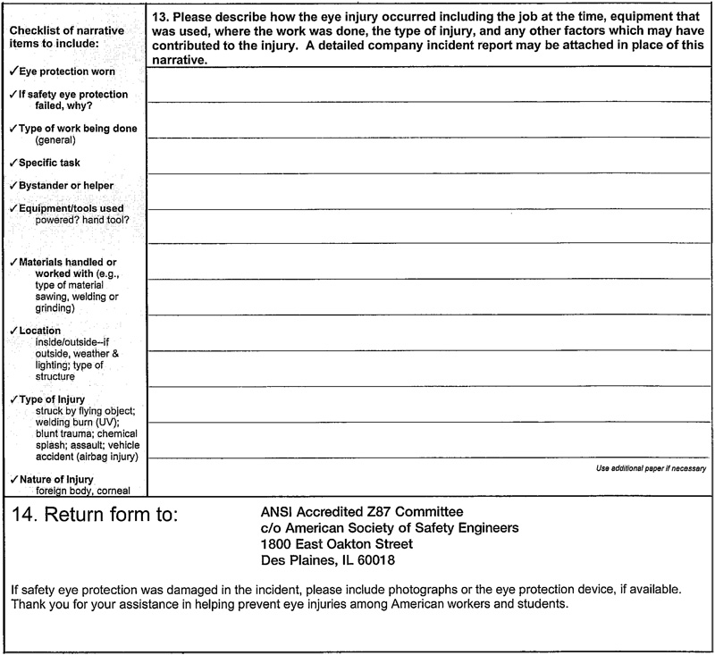
The Selection Chart is intended to aid in identifying and selecting the types of eye and face protectors that are available, their capabilities and limitation for the hazard “source” operations listed. This guide is not intended to be the sole reference in selecting the proper eye and face protector.
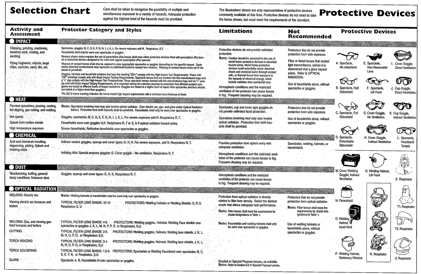
 for the CIE 1931 Standard colorimetric Observer And of Relative Spectral Emittance S (λ) For CIE Illuminant A.