In order to promote public education and public safety, equal justice for all, a better informed citizenry, the rule of law, world trade and world peace, this legal document is hereby made available on a noncommercial basis, as it is the right of all humans to know and speak the laws that govern them.
USAS Z49.1-1967
U.D.C.621.791:614.8
USA Standard
Third Edition
Superseding 1958 Edition
Prepared by USA Standards Committee Z49
Under the Sponsorship of American Welding Society
Edward A. Fenton
Technical Director
Price $4.00
Copyright 1968 by
AMERICAN WELDING SOCIETY, INC.
345 East 47th Street, New York, N. Y. 10017
PRINTED IN THE UNITED STATES OF AMERICA
SECOND PRINTING, APRIL 1968
B iPersonnel
USA Standards Committee Z49
F. C. Saacke CHAIRMAN
H. W. Speicher VICE-CHAIRMAN
R. Mann SECRETARY
AMERICAN CONFERENCE OF GOVERNMENTAL INDUSTRIAL HYGIENISTS:
C. H. Powell, Occupational Health Research and Training Facility
I. Kingsley, (Alternate), New York State Department of Labor
AMERICAN GAS ASSOCIATION:
V. A. Howell, Long Island Lighting Co.
H. W. Becker, (Alternate), American Gas Association
AMERICAN INDUSTRIAL HYGIENE ASSOCIATION:
H. W. Speicher, Westinghouse Electric Corp.
J. J. Ferry, (Alternate), General Electric Co.
AMERICAN INSURANCE ASSOCIATION:
W. M. Apgar1, American Insurance Association
W. H. Van Arnum2, American Insurance Association
AMERICAN IRON AND STEEL INSTITUTE:
J. Matusek, Inland Steel Co.
AMERICAN MUTUAL INSURANCE ALLIANCE:
P. Lange, Employers Mutuals of Wausau
C. S. Laubly, (Alternate), Celanese Corp.
AMERICAN PETROLEUM INSTITUTE:
K. C. Lowe3, American Oil Co.
J. F. McKenna, (Alternate), American Petroleum Institute
AMERICAN PUBLIC HEALTH ASSOCIATION:
W. J. Holland, Public Health Service
AMERICAN SOCIETY OF MECHANICAL ENGINEERS:
A. N. Kugler, Air Reduction Co., Inc.
G. O. Hoglund, (Alternate), Alcoa Technical Center
AMERICAN SOCIETY OF SAFETY ENGINEERS:
E. O. Kumler, Thompson Rumo Wooldridge, Inc.
P. W. Chatterton, (Alternate), American Society of Safety Engineers
AMERICAN WELDING SOCIETY:
F. C. Saacke, Air Reduction Co., Inc.
ASSOCIATED FACTORY MUTUAL FIRE INSURANCE COMPANIES:
L. H. Flanders, Jr., Factory Mutual Engineering Division
AUTOMOBILE MANUFACTURERS ASSOCIATION:
R. W. Batten, Chrysler Engine Plant
CANADIAN STANDARDS ASSOCIATION:
iiE. Mastromatteo, M.D., (Liaison Member), Canadian Department of Health
COMPRESSED GAS ASSOCIATION:
J. J. Crowe, Air Reduction Co., Inc.
L. G. Matthews, (Alternate), Union Carbide Corp.
INDUSTRIAL MEDICAL ASSOCIATION:
C. Demehl, M.D., Union Carbide Corp.
INDUSTRIAL SAFETY EQUIPMENT ASSOCIATION, INC.:
R. G. Tressler, Fiber-Metal Products Co.
C. N. Sumwalt, Jr., (Alternate), Industrial Safety Equipment Association, Inc.
INSTITUTE OF ELECTRICAL AND ELECTRONICS ENGINEERS:
J. H. Lampe, Old Dominion College
INTERNATIONAL ASSOCIATION OF GOVERNMENTAL LABOR OFFICIALS:
R. L. Higgins, New Jersey Department of Labor and Industry
C. F. Haaren, (Alternate), New Jersey Department of Labor and Industry
MECHANICAL CONTRACTORS ASSOCIATION OF AMERICA:
W. E. Maloney4, Joseph Davis, Inc.
H. K. Raisler5, Raisler Corp.
NATIONAL ELECTRICAL MANUFACTURERS ASSOCIATION:
A. N. Kugler6, Air Reduction Co., Inc.
N. G. Schreiner, (Alternate), Union Carbide Corp.
NATIONAL FIRE PROTECTION ASSOCIATION:
W. L. Walls, National Fire Protection Association
NATIONAL SAFETY COUNCIL:
H. J. Weber, American Foundrymen's Society
RESISTANCE WELDER MANUFACTURERS ASSOCIATION:
J. Morrissey, Resistance Welder Corp.
SHIPBUILDERS COUNCIL OF AMERICA:
T. B. Smith, Bethlehem Steel Co.
U. S. DEPARTMENT OF THE AIR FORCE:
Maj. O. W. Kittilstad7, U. S. Department of the Air Force
Lt. Col. C. C. Feightner8, U. S. Department of the Air Force
Lt. Col. R. L. Peterson9, U. S. Department of the Air Force
U. S. DEPARTMENT OF THE ARMY:
W. M. Kennedy, U. S. Army, Office of Chief of Engineers
G. F. Sprague, III, (Alternate), U. S. Army Environmental Hygiene Agency
U. S. DEPARTMENT OF LABOR, BUREAU OF LABOR STANDARDS:
W. J. Jones, Office of Occupational Safety
A. D. Morehouse, (Alternate), Office of Occupational Safety
U. S. DEPARTMENT OF THE NAVY, OFFICE OF INDUSTRIAL RELATIONS:
R. W. Webster, Safety Division, Office of Industrial Relations
U. S. DEPARTMENT OF THE NAVY, NAVAL SHIPS ENGINEERING CENTER:
E. W. Eschbacher, Naval Ship Engineering Center
U. S. PUBLIC HEALTH SERVICE, DEPARTMENT OF HEALTH, EDUCATION AND WELFARE:
J. H. Fanney, Jr., Occupational Health Research & Training Facility
1Appointed, September 1966
2Resigned, August 1966
3Appointed, September 1966
4Appointed, May 1967
5Resigned, May 1967
6Resigned, July 1967
7Appointed, January 1967
8Appointed, October 1965: Resigned, January 1967
9Resigned, September 1965
| Foreword | |||
| Citation | |||
| 1. | Scope | 1 | |
| 2. | Definitions | 1 | |
| 3. | Installation and Operation of Oxygen-Fuel Gas Systems for Welding and Cutting | 2 | |
| 3.1 | General Provisions | 2 | |
| 3.2 | Cylinders and Containers | 3 | |
| 3.3 | Manifolding of Cylinders | 9 | |
| 3.4 | Service Piping Systems | 11 | |
| 3.5 | Protective Equipment, Hose, and Regulators | 17 | |
| 3.6 | Acetylene Generators | 21 | |
| 3.7 | Calcium Carbide Storage | 28 | |
| 3.8 | Public Exhibitions and Demonstrations | 30 | |
| 4. | Application, Installation and Operation of Arc Welding and Cutting Equipment | 31 | |
| 4.1 | General | 31 | |
| 4.2 | Application of Arc Welding Equipment | 32 | |
| 4.3 | Installation of Arc Welding Equipment | 35 | |
| 4.4 | Operation and Maintenance | 37 | |
| 5. | Installation and Operation of Resistance Welding Equipment | ||
| 5.1 | General | 40 | |
| 5.2 | Spot and Seam Welding Machines (Nonportable) | 41 | |
| 5.3 | Portable Welding Machines | 42 | |
| 5.4 | Flash Welding Equipment | 42 | |
| 5.5 | Hazards and Precautions | 43 | |
| 5.6 | Maintenance | 43 | |
| 6. | Fire Prevention and Protection | 43 | |
| 6.1 | Basic Precautions | 43 | |
| 6.2 | Special Precautions | 43 | |
| 6.3 | Welding or Cutting Containers | 45 | |
| 6.4 | Sprinkler Protection | 45 | |
| 6.5 | Confined Spaces | 45 iv | |
| 7. | Protection of Personnel | 46 | |
| 7.1 | General | 46 | |
| 7.2 | Eye Protection | 46 | |
| 7.3 | Protective Clothing | 49 | |
| 7.4 | Work in Confined Spaces | 50 | |
| 8. | Health Protection and Ventilation | 51 | |
| 8.1 | General | 51 | |
| 8.2 | Ventilation for General Welding and Cutting | 53 | |
| 8.3 | Local Exhaust Hoods and Booths | 53 | |
| 8.4 | Ventilation in Confined Spaces | 54 | |
| 8.5 | Fluorine Compounds | 55 | |
| 8.6 | Zinc | 55 | |
| 8.7 | Lead | 55 | |
| 8.8 | Beryllium | 56 | |
| 8.9 | Cadmium | 56 | |
| 8.10 | Mercury | 56 | |
| 8.11 | Other Materials of Toxic Significance | 56 | |
| 8.12 | Brazing Atmospheres | 57 | |
| 8.13 | Cleaning Compounds | 57 | |
| 8.14 | Cutting of Stainless Steels | 58 | |
| 8.15 | Medical Control and First Aid | 58 | |
| 9 | Industrial Applications | 58 | |
| Part I–Construction Industry | 58 | ||
| A. | General | 58 | |
| B. | General Maintenance Welding and Cutting Operations | 59 | |
| C. | Earth Moving and Grading Equipment – Operation and Maintenance | 61 | |
| D. | Fire Protection and Prevention | 61 | |
| E. | Demolition | 62 | |
| F. | Concrete Construction and Masonry | 64 | |
| G. | Tunnels, Shafts and Caissons | 64 | |
| H. | Marine Piling and Marine Construction | 65 | |
| I. | Batch Plant and Road Paving | 65 | |
| J. | Steel Erection | 65 | |
| K. | Transmission Pipeline | 66 | |
| L. | Mechanical Piping Systems | 67 | |
| Bibliography | 68 | ||
During World War II, the increased industrial activity brought on by war production emphasized the need for preserving manpower and avoiding lost-time accidents. Since the existence of proper safety regulations and their use are the first and most important steps in any program of safety and accident prevention, and since welding during World War II was too often done by inexperienced and casually trained personnel, the need for complete information on safety seemed most pressing. Accordingly, in June 1943, the AMERICAN WELDING SOCIETY, the International Acetylene Association, the National Electrical Manufacturers Association and the Division of Labor Standards of the U. S. Department of Labor requested the American Standards Association (now United States of America Standards Institute) to initiate the development of an American War Standard for Safety in Electric and Gas Welding and Cutting Operations. This American War Standard was published in 1944 and was well received by industry, In fact, the American War Standard met such a real need, that it was deemed desirable to initiate a Sectional Committee to prepare an American Standard (now called USA Standards) on the same Subject to supersede the American War Standard, and provide safety recommendations for welding and cutting operations which were applicable to normal peacetime production.
To accomplish this, ASA Sectional Committee Z49, Safety in Electric and Gas Welding and Cutting Operations (now USA Standards Committee Z49, Safety in Welding and Cutting) was organized in March 1946 under the sponsorship of the AMERICAN WELDING SOCIETY. This Committee as organized comprises a wide representation of users and suppliers of welding equipment and welded products, insurance companies, governmental bodies and other organizations interested in welding or cutting. Preparation of this Standard was through meetings of the Committee and its subcommittees and through correspondence. A draft American Standard was first prepared and this was then circulated widely through industry for comment. As the final step all comments and suggestions received were then carefully reviewed. This American Standard was first issued in 1950; the present (third) edition was published in 1968.
This Standard is presented in the hope that adherence to the safety requirements contained herein will result in the elimination of possible hazards due to welding and cutting; hence, the elimination of avoidable accidents and property damage.
The current local, municipal, state, and federal regulations relative to welding, cutting and allied processes shall be observed.
Comments or questions concerning this Standard will be most welcome. They should be sent to Secretary, USA Standards Committee Z49, AMERICAN WELDING SOCIETY, 345 East 47th Street, New York, N. Y. 10017.
viWhere safety officials desire that welding be performed in accordance with the provisions of this Standard, but do not wish to include this Standard in its entirety in their own standard, the following citation may be inserted in their standard:
SAFETY IN WELDING AND CUTTING
“The operation and maintenance of welding and cutting equipment shall conform to the provisions of the USA Standard Z49.1 Safety in Welding and Cutting”
All persons or organizations wishing to republish this material in whole or in part shall consult with the AMERICAN WELDING SOCIETY for permission.
viiNOTE: By publication of this Standard, the American Welding Society does not insure anyone utilizing the Standard against liability arising from the use of such Standard. A publication of a Standard by the American Welding Society does not carry with it the right to make, use or sell any patented items. Each prospective user should make an independent investigation.
viiiSafety in Welding and Cutting
1.1 This standard is for the protection of persons from injury and illness and the protection of property (including equipment) from damage by fire and other causes arising from welding and cutting.
1.2 Specific provisions are included for gas welding, shielded metal are welding, submerged are welding, gas shielded are welding, brazing and resistance welding, However, the requirements of this standard are generally applicable to the other welding processes shown in the AWS Master Chart of Welding Processes, A3.1-61.
1.3 No attempt has been made to include all particular hazards which may be inherent when welding and cutting equipment is used in special industries.
2.1 Shall is used to indicate provisions which are mandatory.
2.2 Should or it is recommended is used to indicate provisions which are not mandatory but which are pointed out here as recommended good practices.
12.3 The words approved or approval as used in this standard mean acceptable to the authority having jurisdiction.
NOTE: For the purpose of this standard it is recommended that the authority having jurisdiction accept welding and cutting equipment that has been tested and listed by Underwriters’ Laboratories, Inc. Chicago, and/or by Factory Mutual Engineering Division, Norwood, Mass.
2.4 The terms welder and welding operator as used herein are intended to designate any operator of electric or gas welding and cutting equipment.
2.5 All other welding terms used herein are in accordance with AWS Definitions – Welding and Cutting, A3.0-61.
3.1.1 Mixtures of fuel gases and air or oxygen may be explosive and shall be guarded against. No device or attachment facilitating or permitting mixtures of air or oxygen with flammable gases prior to consumption, except at the burner or in a standard torch, shall be allowed unless approved for the purpose.
3.1.2 Under no condition shall acetylene be generated, piped (except in approved cylinder manifolds) or utilized at a pressure in excess of 15 psi gage pressure or 30 psi absolute pressure. (The 30 psi absolute pressure limit is intended to prevent unsafe use of acetylene in pressurized chambers such as caissons, underground excavations or tunnel construction.) This requirement is not intended to apply to storage of acetylene dissolved in a suitable solvent in cylinders manufactured and maintained according to Interstate Commerce Commission requirements, or to acetylene for chemical use. The use of liquid, acetylene shall be prohibited.
*LISTED: Equipment or materials included in a list published by a nationally recognized testing laboratory that maintains periodic inspection of production of listed equipment or materials, and whose listing states either that the equipment or material meets nationally recognized standards or has been tested and found suitable for use in a specified manner.
23.1.3 Only approved apparatus (see Par. 2.3) such as torches, regulators or pressure-reducing valves, acetylene generators and manifolds shall be used.
3.1.4 Workmen in charge of the oxygen or fuel-gas supply equipment, including generators, and oxygen or fuel-gas distribution piping systems shall be instructed and judged competent by their employers for this important work before being left in charge. Rules and instructions covering the operation and maintenance of oxygen or fuel-gas supply equipment, including generators, and oxygen or fuel-gas distribution piping systems shall be readily available.
3.2.1 Approval and Marking
3.2.1.1 All portable cylinders used for the storage and shipment of compressed gases shall be constructed and maintained in accordance with the regulations of the Interstate Commerce Commission.*
3.2.1.2 Compressed gas cylinders shall be legibly marked, for the purpose of identifying the gas content, with either the chemical or the trade name of the gas, Such marking shall be by means of stenciling, stamping or labeling, and shall not be readily removable. Whenever practical, the marking shall be located on the shoulder of the cylinder. This method conforms to the Method for Marking Portable Compressed Gas Containers to Identify the Material Contained, USA Standard Z48.1-1954.
3.2.1.3 Compressed gas cylinders shall be equipped with connections complying with the Compressed Gas Cylinder Value Outlet and Inlet Connections, USA Standard B57.1-1965.
3.2.1.4 All cylinders with a water weight capacity of over 30 1bs, shall be equipped with means of connecting a valve protection cap or with a collar or recess to protect the valve.
3.2.2 Storage of Cylinders – General
3.2.2.1 Cylinders shall be kept away from radiators and other sources of heat.
*In Canada, the specifications and regulations of the Board of Transport Commissioners for Canada apply.
33.2.2.2 Inside of buildings, cylinders shall be stored in a well-protected, well-ventilated, dry location, at least 20 feet from highly combustible materials such as oil or excelsior. Cylinders should be stored in definitely assigned places away from elevators, stairs or gangways. Assigned storage spaces shall be located where cylinders will not be knocked over or damaged by passing or falling objects, or subject to tampering by unauthorized persons. Cylinders shall not be kept in unventilated enclosures such as lockers and cupboards.
3.2.2.3 Full cylinders of oxygen and fuel-gas should be used in rotation as received from the supplier.
3.2.2.4 Empty cylinders shall have their valves closed.
3.2.2.5 Valve protection caps, where cylinder is designed to accept a cap, shall always be in place, hand-tight, except when cylinders are in use or connected for use.
3.2.3 Fuel-Gas Cylinder Storage
3.2.3.1 Inside a building, cylinders, except those in actual use or attached ready for use, shall be limited to a total gas capacity of 2000 cubic feet or 300 pounds of liquefied petroleum gas. In large, well-ventilated, one-story buildings, exceptions to this rule may be granted by the proper authorities.
3.2.3.2 For storage in excess of 2000 cubic feet total gas capacity of cylinders or 300 pounds of liquefied petroleum gas, a separate room or compartment conforming to the requirements specified in 3.6.6.1h and 3.6.6.1i shall be provided, or cylinders shall be kept outside or in a special building. Special buildings, rooms or compartments shall have no open flame for heating or lighting and shall be well-ventilated. They may also be used for storage of calcium carbide in quantities not to exceed 600 pounds, when contained in metal containers complying with 3.7.1.1 and 3.7.1.2. Signs should be conspicuously posted in such rooms reading, ‘Danger–No Smoking, Matches or Open Lights.’ or other equivalent wording (See Specifications for Industrial Accident Prevention Signs, USA Standard Z35.1-1959.)
3.2.3.3 Acetylene cylinders shall be stored valve end up.
3.2.4 Oxygen Storage
3.2.4.1 Oxygen cylinders shall not be stored near highly combustible material, especially oil and grease; or near reserve stocks of carbide and acetylene or other fuel-gas cylinders, or near any other substance likely to cause or accelerate fire; or in an acetylene generator compartment.
43.2.4.2 Oxygen cylinders stored in outside generator houses shall be separated from the generator or carbide storage rooms by a noncombustible partition having a fire-resistance rating of at least one hour. This partition shall be without openings and shall be gas-tight.
3.2.4.3 Oxygen cylinders in storage shall be separated from fuel-gas cylinders or combustible materials (especially oil or grease), a minimum distance of 20 feet or by a noncombustible barrier at least 5 feet high having a fire-resistance rating of at least ½ hour.
3.2.4.4 Where a liquid oxygen system is to be used to supply gaseous oxygen for welding or cutting and the system has a storage capacity of (a) more than 13,000 cubic feet of oxygen (measured at 14.7 psia and 70°F), connected in service or ready for service, or (b) more than 25,000 cubic feet of oxygen (measured at 14.7 psia and 70°F), connected in service or ready for service or (b) more than 25,000 cubic feet of oxygen (measured at 14.7 psia and 70°) including unconnected reserves on hand at the site, it shall comply with the provisions of the Standard for Bulk Oxygen Systems at Consumer Sites, NFPA No. 566.
3.2.5 Operating Procedures
3.2.5.1 Oxygen Cylinders
3.2.5.1a The following precautions shall be observed:
Always refer to oxygen by its proper name oxygen and not, for example, by the word air. Oxygen will not burn, but supports and accelerates combustion, and will cause oil and other similar materials to burn with great intensity. Oil or grease in the present of oxygen may ignite and burn violently.
WARNING
A serious accident may easily result if oxygen is used as a substitute for compressed air. Never use oxygen in pneumatic tools, in oil preheating burners, to start internal combustion engines, to blow out pipe lines, to dust clothing or work, to create pressure or for ventilation.
3.2.5.1b Cylinders, cylinder valves, couplings, regulators, hose and apparatus shall be kept free from oily or greasy substances. Oxygen cylinders or apparatus shall not be handled with oily hands or gloves. A jet of oxygen must never be permitted to strike an oily surface, greasy clothes, or enter a fuel oil or other storage tank.
3.2.5.2 Fuel-Gas Cylinders
3.2.5.2a Fuel gases shall be called by their proper names and not by the word gas.
53.2.5.3 Handling–General
3.2.5.3a When transporting cylinders by a crane or derrick, a cradle, boat or suitable platform shall be used. Slings or electric magnets shall not be used for this purpose. Valve-protection caps, where cylinder is designed to accept a cap, shall always be in place.
3.2.5.3b Cylinders should be moved by tilting and rolling them on their bottom edges. Dragging and sliding should be avoided. When cylinders are transported by vehicle they should be secured in position. Cylinders shall not be dropped or struck or permitted to strike each other violently.
3.2.5.3c Valve-protection caps shall not be used for lifting cylinders from one vertical position to another. Bars shall not be used under valves or valve-protection caps to pry cylinders loose when frozen to the ground or otherwise fixed; the use of warm (not boiling) water is recommended. Valve-protection caps are designed to protect cylinder valves from damage. Before raising cylinders provided with valve-protection caps from a horizontal to a vertical position, the cap should be properly in place. The cap should be turned clockwise to see that it is hand-tight.
3.2.5.3d A suitable cylinder truck, chain or steadying device should be used to keep cylinders from being knocked over while in use.
3.2.5.3e Unless cylinders are secured on a special truck, regulators shall be removed and valve-protection caps, when provided for, shall be put in place before cylinders are moved.
3.2.5.3f Cylinders not having fixed hand wheels shall have keys, handles or nonadjustable wrenches on valve stems while these cylinders are in service. In multiple cylinder installations only one key or handle is required for each manifold.
3.2.5.3g Cylinder valves shall be closed before moving cylinders.
3.2.5.3h Cylinder valves shall be closed when work is finished.
3.2.5.3i Valves of empty cylinders shall be closed.
3.2.5.3j Cylinders shall be kept far enough away from the actual welding or cutting operation so that sparks, hot slag or flame will not reach them, or fire-resistant shields shall be provided.
63.2.5.3k Cylinders shall not be placed where they might become part of an electric circuit. Contacts with third rails, trolley wires, etc., shall be avoided. Cylinders shall be kept away from radiators, piping systems, layout tables, etc., that may be used for grounding electric circuits such as for arc welding machines. Any practice such as the tapping of an electrode against a cylinder to strike an arc shall be prohibited.
3.2.5.3l Cylinders shall never be used as rollers or supports, whether full or empty.
3.2.5.3m The numbers and markings stamped into cylinders shall not be tampered with. (Such tampering is illegal.)
3.2.5.3n Empty cylinders should be marked “empty” or “MT”. segregated from full cylinders and promptly returned to the supplier with valve-protection caps in place (See 3.2.5.3a above). All valves shall be closed.
3.2.5.3o No person, other than the gas supplier, shall attempt to mix gases in a cylinder. No one, except the owner of the cylinder or person authorized by him, shall refill a cylinder.
3.2.5.3p No one shall tamper with safety devices in cylinders or valves.
3.2.5.4 Use – Oxygen Cylinders
3.2.5.4a Cylinders shall not be dropped or otherwise roughly handled.
3.2.5.4b Unless connected to a manifold, oxygen from a cylinder shall not be used without first attaching an oxygen regulator to the cylinder valve. Before connecting the regulator to the cylinder valve, the valve shall be opened slightly for an instant and then closed. (This action is generally termed cracking and is intended to clear the valve of dust or dirt that otherwise might enter the regulator.) Always stand to one side of the outlet when opening the cylinder valve.
3.2.5.4c A hammer or wrench shall not be used to open cylinder valves. If valves cannot be opened by hand, the supplier shall be notified.
3.2.5.4d Cylinder valves shall not be tampered with nor should any attempt be made to repair them. If trouble is experienced, the supplier should be sent a report promptly indicating the character of the trouble and the cylinder's serial number. Supplier's instructions as to its disposition shall be followed.
73.2.5.4e After a regulator is attached, an oxygen cylinder valve should be opened slightly at first so that the regulator cylinder-pressure-gage hand moves up slowly; then the valve can be opened all the way. If the high pressure is suddenly released, it is liable to damage the regulator and pressure gages. Stand to one side of the regulator and not in front of the glass-covered gage faces when opening the cylinder valve.
3.2.5.4f When the oxygen cylinder is in use, the valve should be opened fully in order to prevent leakage around the valve stem. Complete removal of the stem from a diaphragm-type cylinder valve shall be avoided.
3.2.5.5 Use – Fuel-Gas Cylinders
3.2.5.5a Fuel-gas cylinders shall be placed with valve end up whenever they are in use. Liquefied gases shall be stored and shipped with the valve end up.
3.2.5.5b Cylinders shall be handled carefully. Rough handling, knocks, or falls are liable to damage the cylinder, valve or safety devices and cause leakage.
3.2.5.5c Before connecting a regulator to a cylinder valve, the valve shall be opened slightly and closed immediately. (This action is generally termed cracking and is intended to clear the valve of dust or dirt that otherwise might enter the regulator). The valve shall be opened while standing to one side of the outlet; never in front of it. Never crack a fuel-gas cylinder valve near other welding work or near sparks, flame or other possible sources of ignition.
3.2.5.5d Before a regulator is removed from a cylinder valve, the cylinder valve shall be closed and the gas released from the regulator.
3.2.5.5e Nothing shall be placed on top of an acetylene cylinder when in use which may damage the safety device or interfere with the quick closing of the valve.
3.2.5.5f If when the valve on a fuel-gas cylinder is opened there is found to be a leak around the valve stem, the valve should be closed and the gland nut tightened. If this does not stop the leak, the use of the cylinder should be discontinued; it should be removed to the out-of-doors, properly tagged and the supplier advised. In case the fuel-gas should leak from the cylinder valve, and cannot be shut off with the valve stem, the cylinder should be removed to the outdoors, properly tagged and the supplier advised. A regulator may be attached to a cylinder valve to stop temporarily a leak through the valve seat.
83.2.5.5g If a leak should develop at a fuse plug or other safety device, the cylinder should be removed to the out-of-doors well away from any source of ignition; the cylinder valve should be opened slightly and the fuel-gas allowed to escape slowly.
3.2.5.5h A warning should be placed near cylinders having leaking fuse plugs or other leaking safety devices not to approach them with a lighted cigarette or other source of ignition. Such cylinders should be plainly tagged; the supplier should be promptly notified and his instructions followed as to their return.
3.2.5.5i Safety devices shall not be tampered with.
3.2.5.5j Fuel-gas shall never be used from cylinders through torches or other devices equipped with shut-off valves without reducing the pressure through a suitable regulator attached to the cylinder valve or manifold.
3.2.5.5k The cylinder valve shall always be opened slowly.
3.2.5.5l An acetylene cylinder valve shall not be opened more than 1 ½ turns of the spindle, and preferably no more than ¾ of a turn.
3.2.5.5m Where a special wrench is required it shall be left in position on the stem of the valve while the cylinder is in use so that the fuel-gas flow can be quickly turned off in case of emergency. In the case of mani-folded or coupled cylinders at least one such wrench shall always be available for immediate use.
3.3.1 Fuel-Gas Manifolds
3.3.1.1 Manifolds shall be approved either separately for each component part or as an assembled unit.
3.3.1.2 Except as provided in 3.3.1.3, fuel-gas cylinders connected to one manifold inside a building shall be limited to a total capacity not exceeding 300 pounds of liquefied petroleum gas or 3000 cubic feet of other fuel-gas. More than one such manifold with connected cylinders may be located in the same room provided the manifolds are at least 50 feet apart or separated by a noncombustible barrier at least 5 ft. high having a fire-resistance rating of at least ½ hour.
3.3.1.3 Fuel-gas cylinders connected to one manifold having an aggregate capacity exceeding 300 pounds of liquefied petroleum gas or 3000 cubic feet of other fuel-gas shall be located outdoors, or in a separate building or room constructed in accordance with 3.6.6.1h and 3.6.6.1i.
93.3.1.4 Separate manifold buildings or rooms may also be used for the storage of drums of calcium carbide and cylinders containing fuel gases as provided in 3.2.3. Such buildings or rooms shall have no open flames for heating or lighting and shall be well-ventilated.
3.3.1.5 High-pressure fuel-gas manifolds shall be provided with approved pressure regulating devices.
3.3.2 High-Pressure Oxygen Manifolds (for use with cylinders having an ICC service pressure above 200 psig)
3.3.2.1 Manifolds shall be approved either separately for each component part or as an assembled unit.
3.3.2.2 Oxygen manifolds shall not be located in an acetylene generator room. Oxygen manifolds shall be separated from fuel-gas cylinders or combustible materials (especially oil or grease), a minimum distance of 20 feet or by a noncombustible barrier at least 5 feet high having a fire-resistance rating of at least ½ hour.
3.3.2.3 Except as provided in 3.3.2.4, oxygen cylinders connected to one manifold shall be limited to a total gas capacity of 6000 cubic feet. More than one such manifold with connected cylinders may be located in the same room provided the manifolds are at least 50 feet apart or separated by a noncombustible barrier at least 5 ft. high having a fire-resistance rating of at least ½ hour.
3.3.2.4 An oxygen manifold, to which cylinders having an aggregate capacity of more than 6000 cubic feet of oxygen are connected, should be located outdoors or in a separate non-combustible building. Such a manifold, if located inside a building having other occupancy, shall be located in a separate room of noncombustible construction having a fire-resistance rating of at least ½ hour or in an area with no combustible material within 20 feet of the manifold.
NOTE: A building having other occupancy refers to a building other than that directly associated with the production of acetylene, the storage of calcium carbide or the storage and manifolding of gases used in welding and cutting.
3.3.2.5 An oxygen manifold or oxygen bulk supply system which has storage capacity of (a) more than 13,000 cubic feet of oxygen (measured at 14.7 psia and 70°F), connected in service or ready for service, or (b) more than 25,000 cubic feet of oxygen (measured at 14.7 psia and 70°F), including unconnected reserves on hand at the site, shall comply with the provisions of the Standard for Bulk Oxygen Systems at Consumer Sites. NFPA No. 566.
103.3.2.6 High-pressure oxygen manifolds shall be provided with approved pressure-regulating devices.
3.3.3. Low-Pressure Oxygen Manifolds (for use with cylinders having an ICC service pressure not exceeding 200 psig).
3.3.3.1 Manifolds shall be of substantial construction suitable for use with oxygen at a pressure of 250 psig. They shall have a minimum bursting pressure of 1000 psig and shall be protected by a safety relief device which will relieve at a maximum pressure of 500 psig.
NOTE: ICC-4L200 cylinders have safety devices which relieve at a maximum pressure of 250 psig (or 235 psig if vacuum insulation is used).
3.3.3.2 Hose and hose connections subject to cylinder pressure shall comply with 3.5.5. Hose shall have a minimum bursting pressure of 1000 psig.
3.3.3.3 The assembled manifold including leads shall be tested and proven gas-tight at a pressure of 300 psig. The fluid used for testing oxygen manifolds shall be oil-free and not combustible.
3.3.3.4 The location of manifolds shall comply with 3.3.2.2, 3.3.2.3, 3.3.2.4, and 3.3.2.5.
3.3.3.5 The following sign shall be conspicuously posted at each manifold:
| LOW-PRESSURE MANIFOLD DO NOT CONNECT HIGH-PRESSURE CYLINDERS MAXIMUM PRESSURE – 250 PSIG |
3.3.4 Portable Outlet Headers
3.3.4.1 The term portable outlet header is used to mean any assembly of valves and connections used for service outlet purposes, which is connected to the permanent service piping system by means of hose or other nonrigid conductors. Devices of this nature are commonly used at piers and drydocks in shipyards where the service piping cannot be located close enough to the work to provide a direct supply.
3.3.4.2 Portable outlet headers shall not be used indoors except for temporary service where the conditions preclude a direct supply from outlets located on the service piping system.
3.3.4.3 Each outlet on the service piping from which oxygen or fuel-gas is withdrawn to supply a portable outlet header shall be equipped with a readily accessible shutoff valve.
113.3.4.4 Hose and hose connections used for connecting the portable outlet header to the service piping shall comply with Section 3.5.5.
3.3.4.5 Master shutoff values for both oxygen and fuel-gas shall be provided at the entry end of the portable outlet header.
3.3.4.6 Portable outlet headers for fuel-gas service shall be provided with an approved hydraulic back-pressure value installed at the inlet and proceding the service outlets, unless an approved pressure-reducing regulator, an approved back-flow check valve, or an approved hydraulic back-pressure valve is installed at each outlet. Outlets provided on headers for oxygen service may be fitted for use with pressure-reducing regulators or for direct hose connection.
3.3.4.7 Each service outlet on portable outlet headers shall be provided with a valve assembly that includes a detachable outlet seal cap, chained or otherwise attached to the body of the valve.
3.3.4.8 Materials and fabrication procedures for portable outlet headers shall comply with Sections 3.4.1, 3.4.2. and 3.4.5.
3.3.4.9 Portable outlet headers shall be provided with frames which will support the equipment securely in the correct operating position and protect them from damage during handling and operation.
3.3.5 Manifold Operating Procedures
3.3.5.1 Cylinder manifolds shall be installed under the supervision of someone familiar with the proper practices with reference to their construction and use.
3.3.5.2 All component parts used in the methods of manifolding described in 3.3.5.9 shall be approved as to materials, design and construction either separately or as an assembled unit.
3.3.5.3 All manifolds and parts used in methods of manifolding shall be used only for the gas or gases for which they are approved.
3.3.5.4 When acetylene cylinders are coupled, approved flash arresters shall be installed between each cylinder and the coupler block. For out door use only, and where the number of cylinders coupled does not exceed 3, one flash arrester installed between the coupler block and regulator is acceptable.
3.3.5.5 Each fuel-gas cylinder lead should be provided with a backflow check valve.
123.3.5.6 The aggregate capacity of fuel-gas cylinders connected to a portable manifold inside a building shall not exceed 3000 cubic feet of gas.
3.3.5.7 Acetylene and liquefied fuel-gas cylinders shall be manifolded in a vertical position.
3.3.5.8 The pressure in the gas cylinders connected to and discharged simultaneously through a common manifold shall be approximately equal.
3.3.5.9 Manifolding Cylinders for Direct Supply to Consuming Devices
NOTE: The units described in 3.3.5.9b and 3.3.5.9c are generally called Portable Manifolds.
3.3.5.9a In one type of manifolding the gas passes from the cylinders through individual cylinder leads to a single, common coupler block and from there through a single common coupler block and from there through a single common pressure-reducing regulator to the consuming device.
3.3.5.9b In a second type of manifolding the cylinders are connected together in sequence. The individual cylinders are provided with coupler tees attached to the cylinder valve. The gas content of each cylinder passes through the coupler tee and joins the main gas stream flowing through a common line composed of leads joining coupler tee to successive coupler tee. A properly supported regulator serves the entire group of connected cylinders.
3.3.5.9c The aggregate capacity of fuel-gas cylinders connected as a unit inside a building as described in 3.3.5.9a or 3.3.5.9b shall not exceed 3000 cubic feet of gas or 300 lbs. in the case of liquefied petroleum gas.
3.4.1 Materials and Design
3.4.1.1 General
3.4.1.1a Piping and fittings shall comply with Section 2, Industrial Gas and Air Piping Systems, of the Code for Pressure Piping, USA Standard B31.1-1955, insofar as it does not conflict with Section 3.4.2 and except as follows:
3.4.1.1b Piping shall be steel, wrought iron, brass or copper pipe, or seamless copper, brass or stainless steel tubing, except as provided in 3.4.1.2 and 3.4.1.3.
3.4.1.2 Oxygen Piping
3.4.1.2a Oxygen piping and fittings at pressures in excess of 700 psig, shall be stainless steel or copper alloys.
3.4.1.2b Hose connections and hose complying with Section 3.5.5 may be used to connect the outlet of a manifold pressure regulator to piping providing the working pressure of the piping is 250 psig or less and the length of the hose does not exceed 5 feet. Hose shall have a minimum bursting pressure of 1000 psig.
3.4.1.2c When oxygen is supplied to a service piping system from a low-pressure oxygen manifold without an intervening pressure regulating device, the piping system shall have a minimum design pressure of 250 psig. A pressure regulating device shall be used at each station outlet when the connected equipment is for use at pressures less than 250 psig.
3.4.1.3 Piping for Acetylene and Acetylenic Compounds
3.4.1.3a Piping for acetylene or acetylenic compounds shall be steel or wrought iron.
3.4.1.3b Unalloyed copper shall not be used for acetylene or acetylenic compounds except in listed equipment.
3.4.2 Piping Joints
3.4.2.1 Joints in steel or wrought iron piping shall be welded, threaded or flanged. Fittings, such as ells, tees, couplings and unions, may be rolled, forged or cast steel, malleable iron or nodular iron. Gray or white cast iron fittings are prohibited.
3.4.2.2 Joints in brass or copper pipe shall be welded, brazed, threaded or flanged. If of the socket type, they shall be brazed with silver-brazing alloy or similar high melting point (not less than 800°F) filler metal.
3.4.2.3 Joints in seamless copper, brass, or stainless steel tubing shall be approved gas tubing fittings or the joints shall be brazed. If of the socket type, they shall be brazed with silver-brazing alloy or similar high melting point (not less than 800°F) filler metal.
143.4.2.4 Threaded connections in oxygen piping should be tinned or made up with litharge and glycerine (litharge and water are sometimes used for service pressures over 300 psi.) or other joint compounds approved for oxygen service, applied to the externally threaded portion.
3.4.3 Installation
3.4.3.1 Distribution lines shall be installed and maintained in a safe operating condition.
3.4.3.2 Piping located inside or outside of buildings may be placed above or below ground. All piping shall be run as directly as practicable, protected against physical damage, proper allowance being made for expansion and contraction, jarring and vibration. Pipe laid underground in earth shall be located below the frost line and protected against corrosion. After assembly, piping shall be thoroughly blown out with air, nitrogen or carbon dioxide to remove foreign materials. For oxygen piping, only oil-free air, oil-free nitrogen or oil-free carbon dioxide shall be used.
3.4.3.3 Only piping which has been welded or brazed shall be installed in tunnels, trenches or ducts. Shut-off valves shall be located outside such conduits. Oxygen piping may be placed in the same tunnel, trench or duct with fuel-gas pipe lines, provided there is good natural or forced ventilation.
3.4.3.4 Low points in piping carrying moist gas shall be drained into drip pots constructed so as to permit pumping or draining out the condensate at necessary intervals. Drain valves shall be installed for this purpose having outlets normally closed with screw caps or plugs. No open-end valves or petcocks shall be used, except that in drips located out-of-doors, underground, and not readily accessible, valves may be used at such points if they are equipped with means to secure them in the closed position. Pipes leading to the surface of the ground shall be cased or jacketed where necessary to prevent loosening or breaking.
3.4.3.5 Gas cocks or valves shall be provided for all buildings at points where they will be readily accessible for shutting off the gas supply to these buildings in any emergency. Underground valve boxes or manholes should be avoided wherever possible. There shall also be provided a shut-off valve in the discharge line from the generator, gas holder, manifold or other source of supply.
3.4.3.6 Shut-off valves shall not be installed in safety relief lines in such a manner that the safety relief device can be rendered ineffective.
153.4.3.7 Fittings and lengths of pipe shall be examined internally BEFORE ASSEMBLY and, if necessary, freed from scale or dirt. Oxygen piping and fittings shall be washed out with a suitable solution which will effectively remove grease and dirt but will not react with oxygen.
NOTE: Hot water solutions of caustic soda or trisodium phosphate are effective cleaning agents for this purpose.
3.4.3.8 Piping shall be thoroughly blown out after assembly to remove foreign materials. For oxygen piping, oil-free air, oil-free nitrogen or oil free carbon dioxide shall be used. For other piping, air or insert gas may be used.
3.4.3.9 When flammable gas lines or other parts of equipment are being purged of air or gas, open lights or other sources of ignition shall not be permitted near uncapped openings.
3.4.3.10 The surface temperature of acetylene pipe lines should not be allowed to exceed 130°F.
3.4.3.11 No welding or cutting shall be performed on an acetylene or oxygen pipe line, including the attachment of hangers or supports, until the line has been purged. Only oil-free nitrogen or oil-free carbon dioxide shall be used to purge oxygen lines.
3.4.4 Painting and Signs
3.4.4.1 Underground pipe and tubing and outdoor ferrous pipe and tubing shall be covered or painted with a suitable material for protection against corrosion.
3.4.4.2 Aboveground piping systems shall be marked in accordance with the Scheme for the Identification of Piping Systems, USA Standard A13.1-1956.
3.4.4.3 Station outlets shall be marked to indicate the name of the gas.
3.4.4.4 Signs clearly establishing the location and identity of section shutoff valves should be provided.
3.4.5 Testing
3.4.5.1 Piping systems shall be tested and proved gas-tight at one-and one-half times the maximum operating pressure, and shall be thoroughly purged of air before being placed in service. The material used for testing oxygen lines shall be oil-free and noncombustible. Flames shall not be used to detect leaks.
3.4.5.2 When flammable gas lines or other parts of equipment are being purged of air or gas, sources of ignition shall not be permitted near uncapped openings.
163.5.1 General
3.5.1.1 Equipment shall be installed and used only in the service for which it is approved and as recommended by the manufacturer.
3.5.2 Pressure Relief for Service Piping Systems
3.5.2.1 Service piping systems shall be protected by pressure relief devices set to function at not more than the design pressure of the systems and discharging upwards to a safe location.
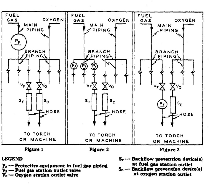
3.5.3 Piping Protective Equipment
3.5.3.1 The fuel-gas and oxygen piping systems, including portable outlet headers shall incorporate the protective equipment shown in Figures 1, 2, or 3.
3.5.3.1a When only a portion of a fuel-gas system is to be used with oxygen, only that portion need comply with 3.5.3.1.
3.5.3.2 Approved protective equipment (designated PF in Figures 1, 2 & 3) shall be installed in fuel-gas piping to prevent:
NOTE: The three functions of the protective equipment may be combined in one device or may be provided by separate devices.
3.5.3.2a The protective equipment shall be located in the main supply line, as in Figure 1; or at the head of each branch line, as in Figure 2; or at each location where fuel-gas is withdrawn, as in Figure 3. Where branch lines are of 2-inch pipe size or larger or of substantial length, protective equipment (designated as PF) shall be located as shown in either Fig. 2 or Fig. 3.
3.5.3.2b Backflow protection shall be provided by an approved device that will prevent oxygen from flowing into the fuel-gas system or fuel from flowing into the oxygen system (See SF, Figs. 1 & 2).
3.5.3.2c Flash-back protection shall be provided by an approved device that will prevent flame from passing into the fuel-gas system.
3.5.3.2d Back-pressure protection shall be provided by an approved pressure-relief device set at a pressure not greater than the pressure rating of the backflow or the flash-back protection device, whichever is
17lower. The pressure-relief device shall be located on the downstream side of the backflow and flash-back protection devices. The vent from the pressure-relief device shall be at least as large as the relief device inlet and shall be installed without low points that may collect moisture, If low points are unavoidable, drip pots with drains closed with screw plugs or caps shall be installed at the low points. The vent terminus shall not endanger personnel or property through gas discharge; shall be located away from ignition sources; and shall terminate in a hood or bend.
3.5.3.3 If pipeline protective equipment incorporates a liquid, the liquid level shall be maintained, and a suitable antifreeze may be used to prevent freezing.
Figure 1, 2, & 3 – Schematic Arrangements of Piping and Station Outlet Protective Equipment. (See Sections 3.5.3, and 3.5.4)
183.5.3.4 Fuel-gas for use with equipment not requiring oxygen shall be withdrawn upstream of the piping protective devices.
3.5.3.5 Where a compressor or booster pump is used in a fuel-gas system requiring oxygen and where this fuel-gas is withdrawn from a source that also supplied a system not requiring oxygen, the latter system should incorporate a check valve to prevent possible backflow.
3.5.4 Station Outlet Protective Equipment
3.5.4.1 A check valve, pressure regulator, hydraulic seal, or combination of these devices shall be provided at each station outlet, including those on portable headers, to prevent backflow, as shown in Figures 1, 2, and 3 and designated as SF and SO.
3.5.4.2 When approved pipeline protective equipment (designated PF) is located at the station outlet as in Figure 3, no additional check valve, pressure regulator, or hydraulic seal is required.
3.5.4.3 A shutoff valve (designated VF and VO) shall be installed at each station outlet and shall be located on the upstream side of other station outlet equipment.
3.5.4.4 If the station outlet is equipped with a detachable regulator, the outlet shall terminate in a union connection that complies with the Regulator Connection Standards, 1958, Compressed Gas Association.
3.5.4.5 If the station outlet is connected directly to a hose, the outlet shall terminate in a union connection complying with the Standard Hose Connection Specifications, 1957, Compressed Gas Association.
3.5.4.6 Station outlets may terminate in pipe threads to which permanent connections are to be made, such as to a machine.
3.5.4.7 Station outlets shall be equipped with a detachable outlet seal cap secured in place. This cap shall be used to seal the outlet except when a hose, a regulator, or piping is attached.
3.5.4.8 Where station outlets are equipped with approved backflow and flash-back protective devices, as many as four torches may be supplied from one station outlet through rigid piping, provided each outlet from such piping is equipped with a shutoff valve and provided the fuel-gas capacity of any one torch does not exceed fifteen cubic feet per hour.
19NOTE: Paragraph 3.5.4.8 does not apply to machines.
3.5.5 Hose and Hose Connections
3.5.5.1 Hose for oxy-fuel gas service shall comply with the Specification for Rubber Welding Hose, 1958, Compressed Gas Association and Rubber Manufacturers Association.
3.5.5.2 The generally recognized colors are red for acetylene and other fuel-gas hose, green for oxygen hose, and black for inert-gas and air hose.
3.5.5.3 When parallel lengths of oxygen and acetylene hose are taped together for convenience and to prevent tangling, not more than four inches out of twelve inches shall be covered by tape.
3.5.5.4 Metal-clad or armored hose is not recommended. However, as part of a machine or an appliance when conditions of use make metal reinforcing advantageous, hose may be used in which such metal reinforcing is exposed to neither the inside gases nor the outside atmosphere.
3.5.5.5 Hose connections shall comply with the Standard Hose Connection Specifications, 1957, Compressed Gas Association.
3.5.5.6 Hose connections shall be clamped or otherwise securely fastened in a manner that will withstand, without leakage, twice the pressure to which they are normally subjected in service, but in no case less than a pressure of 300 psi. Oil-free air or an oil-free inert gas shall be used for the test.
3.5.5.7 Hose showing leaks, burns, worn places, or other defects rendering it unfit for service shall be repaired or replaced.
3.5.6 Pressure-Reducing Regulators
3.5.6.1 Pressure-reducing regulators shall be used only for the gas and pressures for which they are intended. The regulator inlet connections shall comply with Regulator Connection Standards, 1958, Compressed Gas Association.
3.5.6.2 Regulators should be drained of gas before they are attached to a cylinder, or before the cylinder valve is open.
3.5.6.3 Regulators should be returned to the supplier for repairs, calibrations, or adjustments. When regulators or parts of regulators, including gages, need repair, the work shall be performed by skilled mechanics who have been properly instructed.
3.5.6.4 Gages on oxygen regulators shall be marked “USE NO OIL.”
3.5.6.5 Union nuts and connections on regulators shall be inspected before use to detect fault seats which may cause leakage of gas when the regulators are attached to the cylinder valves. Damaged nuts or connections shall be destroyed.
203.6.1 Approval and Marking
3.6.1.1 Generators shall be of approved construction and shall be plainly marked with the maximum rate of acetylene in cubic feet per hour for which they are designed; the weight and size of carbide necessary for a single charge; the manufacturer's name and address; and the name or number of the type of generator.
3.6.1.2 Carbide shall be of the size marked on the generator nameplate.
3.6.2 Rating and Pressure Limitations
3.6.2.1 The total hourly output of a generator shall not exceed the rate for which it is approved and marked. Unless specifically approved for higher ratings, carbide-feed generators shall be rated at one cubic foot per hour per pound of carbide required for a single complete charge.
3.6.2.2 Relief valves shall be regularly operated to insure proper functioning. Relief valves for generating chambers shall be set to open at a pressure not in excess of 15 psig. Relief valves for hydraulic back pressure valves shall be set to open at a pressure not in excess of 20 psig.
3.6.2.3 Nonautomatic generators shall not be used for generating acetylene at pressures exceeding 1 psig, and all water overflows shall be visible.
3.6.3 Location
3.6.3.1 Stationary generators should preferably be placed outside of buildings in generator houses constructed and located in compliance with the applicable sections of 3.6.6, but the installation of approved generators within buildings in accordance with the applicable sections of 3.6.6 of this standard is permissible.
3.6.3.2 The space around the generator shall be ample for free, unobstructed operation and maintenance and shall permit ready adjustment and charging.
3.6.4 Stationary Acetylene Generators (Automatic and Nonautomatic)
3.6.4.1 Installation
3.6.4.1a The foundation shall be so arranged that the generator will be level and so that no excessive strain, will be placed on the generator or its connections. Acetylene generators shall be grounded.
3.6.4.1b Generators shall be placed where water will not freeze. The use of common salt (sodium chloride) or other corrosive chemicals for protection against freezing is not permitted. (For heating systems see 3.6.6.3.)
213.6.4.1c Except when generators are prepared in accordance with 3.6.7.6, sources of ignition shall be prohibited in outside generator houses or inside generator rooms.
3.6.4.1d Water shall not be supplied through a continuous connection to the generator except when the generator is provided with an adequate open overflow or automatic water shutoff which will effectively prevent overfilling of the generator. Where a noncontinuous connection is used, the supply line shall terminate at a point not less than 2 in. above the regularly provided opening for filling so that the water can be observed as it enters the generator.
3.6.4.1e Unless otherwise specifically approved, generators shall not be fitted with continuous drain connections leading to sewers, but shall discharge through an open connections leading to sewers, but shall discharge an open connection into a suitably vented outdoor receptacle or residue pit which may have such connections.
NOTE: An open connection for the sludge draw-off is desirable to enable the generator operator to observe leakage of generating water from the drain valve or sludge cock.
3.6.4.2 Vent Pipes
3.6.4.2a Each generator shall be provided with a vent pipe of Schedule 40 galvanized iron or steel, except that outside of buildings, vent pipes larger than 4 inches, in diameter may be not less than 14 gage galvanized tubing or sheet steel.
3.6.4.2b The escape or relief pipe shall be rigidly installed without traps and so that any condensation will drain back to the generator.
3.6.4.2c The escape or relief pipe shall be carried full size to a suitable point outside the building. It shall terminate in a hood or bend located at least 12 ft. above the ground, preferably above the roof, and as far away as practicable from windows or other openings into buildings and as far away as practicable from sources of ignition such as flues or chimneys and tracks used by locomotives. Generating chamber relief pipes shall not be interconnected but shall be separately led to the outside air. The hood or bend shall be so constructed that it will not be obstructed by rain, snow, ice, insects or birds. The outlet shall be at least 3ft. from combustible construction.
3.6.4.3 Gas Holders
3.6.4.3a Gas holders shall be constructed on the gasometer principle, the bell being suitably guided. The gas bell shall move freely without tendency to bind and shall have a clearance of at last 2 inches from the shell.
223.6.4.3b The gas holder may be located in the generator room, in a separate room or out-of-doors. In order to prevent collapse of the gas bell or infiltration of air due to a vacuum caused by the compressor or booster pump or cooling of the gas, a compressor or booster cut-off shall be provided at a point 12 inches or more above the landing point of the bell. When the gas holder is located indoors, the room shall be ventilated in accordance with 3.6.6.2 and heated and lighted in accordance with 3.6.6.3 through 3.6.6.4.
3.6.4.3c When the gas holder is not located within a heated building, gas holder seals shall be protected against freezing.
3.6.4.3d Means shall be provided to stop the generator-feeding mechanism before the gas holder reaches the upper limit of its travel.
3.6.4.3e When the gas holder is connected to only one generator, the gas capacity of the holder shall be not less than one-third of the hourly rating of the generator.
3.6.4.3f If acetylene is used from the gas holder without increase in pressure at some points but with increase in pressure by a compressor or booster pump at other points, approved piping protective devices shall be installed in each supply line. The low-pressure protective device shall be located between the gas holder and the shop piping, and the medium-pressure protective device shall be located between the compressor or booster pump and the shop piping. (see Figure 4.)
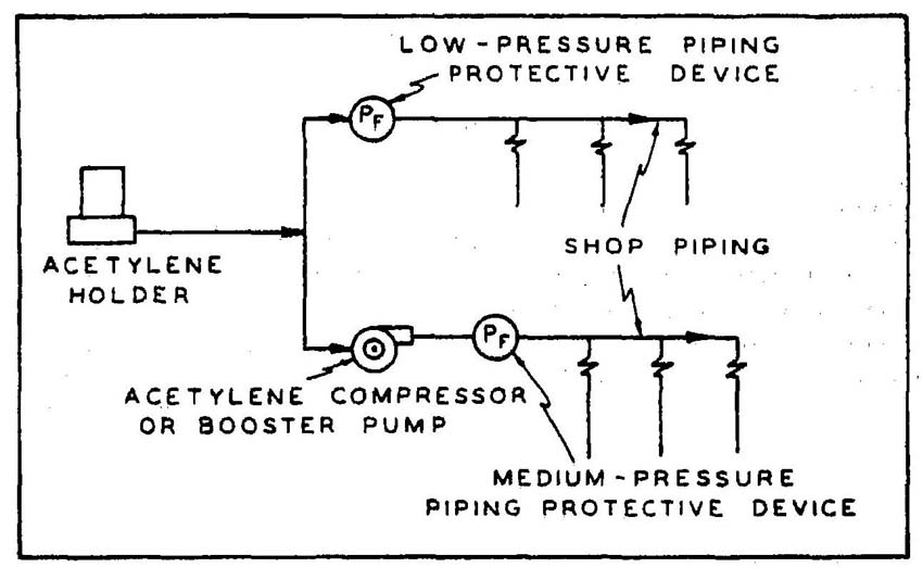
Figure 4 – Protective devices for gas holders, compressors and boosters pumps.
23NOTE: Approved protective equipment (designated PF) is used to prevent;
The three functions of the protective equipment may be combined in one device or may be provided by separate devices.
3.6.4.4 Compressor or Booster Pumps
3.6.4.4a The compressor or booster system shall be of an approved type.
3.6.4.4b Wiring and electrical equipment in compressor or booster pump rooms or enclosures shall conform to the provisions of the National Electrical Code, USA Standard C1-1965, Article 501, for Class I, Division 2 locations.
3.6.4.4c Compressors and booster pump equipment shall be located in well-ventilated areas away from open flames, electrical or mechanical sparks, or other ignition sources.
3.6.4.4d Compressor or booster pumps shall be provided with pressure relief valves which will relieve pressure exceeding 15 psig to a safe outdoor location as provided in 3.6.4.2, or by returning the gas to the inlet side or to the gas supply source.
3.6.4.4e The booster pump should be water-cooled with visible water supply or arranged with an interlocking device to shut down the booster pump in case of failure of the cooling-water supply.
3.6.4.4f Compressor or booster pump discharge outlets shall be provided with approved protective equipment. (See Section 3.5)
3.6.5 Portable Acetylene Generators
3.6.5.1 General
3.6.5.1a All portable generators shall be of a type approved for portable use.
3.6.5.1b Portable generators shall not be used within 10 feet of combustible material other than the floor.
3.6.5.1c Portable generators shall not be used in rooms of total volume less than 35 times the total gas-generating capacity per charge* of all generators in the room. Generators shall not be used in rooms having a ceiling height of less than 10 feet.
*To obtain the gas-generating capacity in cubic feet per charge, multiply the pounds of carbide per charge by 4.5.
243.6.5.1d Portable generators shall be protected against freezing. The use of salt or other corrosive chemical to prevent freezing is prohibited.
3.6.5.2 Operation and Maintenance
3.6.5.2a Portable generators shall be cleaned and recharged and the air mixture blown off outside buildings. In large, well-ventilated, one-story buildings, exceptions to this rule may be granted by the proper authorities.
3.6.5.2b When charged with carbide, portable generators shall not be moved by crane or derrick.
3.6.5.2c When not in use, portable generators shall not be stored in rooms in which open flames are used unless the generators contain no carbide and have been thoroughly purged of acetylene. Storage rooms shall be well-ventilated.
3.6.5.2d When portable acetylene generators are to be transported and operated on vehicles, they shall be securely anchored to the vehicles. If transported by truck, the motor shall be turned off during charging, cleaning and generating periods.
3.6.5.2e Portable generators shall be located at a safe distance from the welding position so that they will not be exposed to sparks, slag, or misdirection of the torch flame or overheating from hot materials or processes.
3.6.6 Outside Generator Houses and Inside Generator Rooms for Stationary Acetylene Generators
3.6.6.1 Construction
3.6.6.1a No opening in any outside generator house shall be located within five feet of any opening in another building.
3.6.6.1b Walls, floors, and roofs of outside generator houses shall be of noncombustible construction.
3.6.6.1c When a part of the generator house is to be used for the storage or manifolding of oxygen cylinders, the space to be so occupied shall be separated from the generator or carbide storage section by partition walls continuous from floor to roof or ceiling, of the type of construction stated in 3.6.6.1h. Such separation walls shall be without openings and shall be joined to the floor, other walls and ceiling or roof in a manner to effect a permanent gas-tight joint.
3.6.6.1d Exit doors shall be located so as to be readily accessible in case of emergency.
253.6.6.1e Explosion venting for outside generator houses and inside generator rooms shall be provided in exterior walls or roofs. The venting area shall be equal to not less than one square foot per 50 cubic feet of room volume and may consist of any one or any combination of the following; walls of light, noncombustible material preferably single-thickness, single-strength glass; lightly fastened batch covers; lightly fastened swinging doors in exterior walls of opening outward; lightly fastened walls or roof designed to relieve at a maximum pressure of 25 pounds per square foot.
3.6.6.1f The installation of acetylene generators within buildings shall be restricted to buildings not exceeding one story in height; provided, however, that this will not be construed as prohibiting such installations on the roof or top floor of a building exceeding such height.
3.6.6.1g Generators installed inside buildings shall be enclosed in a separate room of ample size.
3.6.6.1h The walls, partitions, floors, and ceilings of inside generator rooms shall be of noncombustible construction having a fire-resistance rating of at least one hour. The walls or partitions shall be continuous from floor to ceiling and shall be securely anchored. At least one wall of the room shall be an exterior wall.
3.6.6.1i Openings from an inside generator room to other parts of the buildings shall be protected by a swinging type, self-closing fire door for a Class B opening and having a rating of at least one hour. Windows in partitions shall be wired glass and approved metal frames with fixed sash. Installation shall be in accordance with the Standard for the Installation of Fire Doors and Windows, NFPA No. 80.
3.6.6.2 Ventilation
3.6.6.2a Inside generator rooms or outside generator houses shall be well-ventilated with vents located at floor and ceiling levels.
3.6.6.3 Heating
3.6.6.3a Heating shall be by steam, hot water, enclosed electrically heated elements or other indirect means. Heating by flames or fires shall be prohibited in outside generator houses or inside generator rooms, or in any enclosure communicating with them.
3.6.6.4 Lighting
3.6.6.4a Generator houses or rooms shall have natural light during daylight hours. Where artificial lighting is necessary it shall be restricted to electric lamps installed in a fixed position. Unless specifically approved for use in atmospheres containing acetylene, such lamps shall be provided
26with enclosures of glass or other noncombustible material so designed and constructed as to prevent gas vapors from reaching the lamp or socket and to resist breakage. Rigid conduit with threaded connections shall be used.
3.6.6.4b Lamps installed outside of wired-glass panels set in gas-tight frames in the exterior walls or roof of the generator house or room are acceptable.
3.6.6.5 Electrical Equipment
3.6.6.5a Electric switches, telephones and all other electrical apparatus which may cause a spark, unless specifically approved for use inside acetylene generator rooms, shall be located outside the generator house or in a room or space separated from the generator room by a gas-tight partition, except that where the generator system is designed so that no carbide fill opening or other part of the generator is open to the generator house or room during the operation of the generator, and so that residue is carried in closed piping from the residue discharge valve to a point outside the generator house or room, electrical equipment in the generator house or room shall conform to the provisions of the National Electrical Code, USA Standard C1-1965, Article 501, for Class I, Division 2 locations.
3.6.7 Maintenance and Operation
3.6.7.1 Unauthorized persons shall not be permitted in outside generator houses or inside generator rooms.
3.6.7.1a Operating instructions shall be posted in a conspicuous place near the generator or kept in a suitable place available for ready reference.
3.6.7.1b When recharging generators the order of operations specified in the instructions supplied by the manufacturer shall be followed.
3.6.7.2a In the case of batch-type generators, when the charge of carbide is exhausted and before additional carbide is added, the generating chamber shall always be flushed out with water, renewing the water supply in accordance with the instruction card furnished by the manufacturer.
3.6.7.2b The water-carbide residue mixture drained from the generator shall not be discharged into sewer pipes or stored in areas near open flames. Clear water from residue settling pits may be discharged into sewer pipes.
273.6.7.3 The carbide added each time the generator is recharged shall be sufficient to refill the space provided for carbide without ramming the charge. Steel or other ferrous tools shall not be used in distributing the charge.
3.6.7.4 Generator water chambers shall be kept filled to proper level at all times except while draining during the recharging operation.
3.6.7.5 Whenever repairs are to be made or the generator is to be charged or carbide is to be removed, the water chamber shall be filled to the proper level.
3.6.7.6 Previous to making repairs involving welding, soldering or other hot work or other operations which produce a source of ignition, the carbide charge and feed mechanism shall be completely removed. All acetylene shall be expelled by completely flooding the generator shell with water and the generator shall be disconnected from the piping system. The generator shall be kept filled with water, if possible, or positioned to hold as much water as possible.
3.6.7.7 Hot repairs shall not be made in a room where there are other generators unless all the generators and piping have been purged of acetylene. Hot repairs should preferably be made out-of-doors.
3.7.1 Packaging
3.7.1.1 Calcium carbide shall be contained in metal packages of sufficient strength to prevent rupture. The packages shall be provided with a screw top or equivalent. These packages shall be constructed water and air-tight. Solder shall not be used in such a manner that the package would fail if exposed to fire.
3.7.1.2 Packages containing calcium carbide shall be conspicuously market “Calcium Carbide – Dangerous If Not Kept Dry” or with equivalent warning.
3.7.1.3 CAUTION: Metal tools, even the so-called spark resistant type may cause ignition of an acetylene and air mixture when opening carbide containers.
3.7.1.4 Drums should be handled so that they will not be punctured or ruptured. Full drums of calcium carbide should be used in rotation as received from the supplier.
283.7.1.5 A conspicuous sign should be posted on all calcium carbide storage rooms or buildings reading “Danger – No Smoking, matches or open lights. In case of fire do not use water,” or other equivalent wording. (See Specifications for Industrial Accident Prevention Signs, USA Standard Z35.1-1959.)
3.7.1.6 Sprinkle systems shall not be installed in carbide storage rooms.
3.7.2 Storage Indoors
3.7.2.1 Storage – Under 600 Lbs.
3.7.2.1a Calcium carbide in quantities not to exceed 600 pounds may be stored indoors in dry, waterproof and well-ventilated locations.
3.7.2.1b Calcium carbide not exceeding 600 pounds may be stored indoors in the same room with fuel-gas cylinders.
3.7.2.1c Packages of calcium carbide, except for one of each size, shall be kept sealed. The seals shall not be broken when there is carbide in excess of one pound in any other unsealed package of the same size of carbide in the room.
3.7.2.2 Storage – 600 Lbs. to 5000 Lbs.: Calcium carbide exceeding 600 pounds but not exceeding 5000 pounds shall be stored:
3.7.2.2a In accordance with 3.7.2.3; or
3.7.2.2b In an inside generator room or outside generator house; or
3.7.2.2c In a separate room in a one-story building which may contain other occupancies, but without cellar or basement beneath the carbide storage section. such rooms shall be constructed in accordance with 3.6.6.1h and 3.6.6.1i and ventilated in accordance with 3.6.6.2a. These rooms shall be used for no other purpose.
3.7.2.3 Storage – Over 5000 Lbs.
3.7.2.3a Calcium carbide in excess of 5000 pounds shall be stored in one story buildings without cellar or basement and used for no other purpose, or in outside generator houses. The location of such storage buildings shall be away from congested mercantile and manufacturing districts. If the storage building is of noncombustible construction, it may adjoin other one-story buildings if separated therefrom by unpaired fire walls; if it is detached less than 10 feet from such building or buildings, there shall be no opening in any of the mutually exposing sides of such
29buildings within 10 feet. If the storage building is of combustible construction, it shall be at least 20 feet from any other one or two-story building, and at least 30 feet from any other building exceeding two stories.
3.7.3 Storage Outdoors
3.7.3.1 Calcium carbide in unopened metal containers may be stored outdoors.
3.7.3.2 Carbide containers to be stored outdoors shall be examined to make sure that they are in good condition. Periodic re-examinations shall be made for rusting or other damage to a container that might affect its water or air tightness.
3.7.3.3 Containers should be stored horizontally in single or double rows. Ample space should be provided between rows or pairs of rows to facilitate periodic re-examination and the removal of containers found defective. The bottom tier of each row shall be placed on wooden planking or equivalent, so that the containers will not come in contact with the ground or ground water.
3.7.3.4 Storage areas shall be at least 10 feet from lines of adjoining property that may be built upon.
3.7.3.5 Containers of carbide which have been in storage the longest shall be used first.
3.8.1 General
3.8.1.1. These requirements are intended to promote the safe usage of oxygen-fuel-gas systems in welding and cutting operations at public exhibitions, demonstrations, displays, and trade shows referred to hereinafter as the “site”
3.8.1.2 Installation and operation of welding, cutting and related equipment shall be done by, or under the supervision of, a competent operator to insure the personal protection of viewers and demonstrators as well as the protection from fire, of materials in and around the site and the building itself.
3.8.1.3 Procedures
3.8.1.3a Cylinders containing compressed gases for use at the site shall not be charged in excess of one-half their maximum permissible content. (Cylinders of nonliquefied gases and acetylene shall be charged to not more than one-half their maximum permissible charged pressure in psig, Cylinders of liquefied gases shall be charged to not more than one-half the maximum permissible capacity in pounds.)
303.8.1.3b Cylinders located at the site shall be connected for use except that enough additional cylinders may be stored at the site to furnish approximately one day's consumption of each gas used. Other cylinders shall be stored in an approved storage area, preferably outdoors, but this storage area shall not be located near a building exit.
3.8.1.3c Cylinders in excess of 40 pounds total weight being transported to or from the site shall be carried on a hand or motorized truck.
3.8.1.3d The site shall be constructed, equipped and operated in such a manner that the demonstration will be carried out so as to minimize the possibility of injury to viewers.
3.8.1.3e Sites involving the use of compressed gases shall be located so as not to interfere with the egress of people during an emergency.
3.8.1.3f The Fire Department shall be notified in advance of such use of the site.
3.8.1.3g
3.8.1.3h Hoses shall be located and protected so that they will not be physically damaged.
3.8.1.3i
4.1.1 Welding equipment shall be chosen for safe application to the work to be done as specified in 4.2.
4.1.2 Welding equipment shall be installed safely as specified by 4.3.
314.1.3 Workmen designated to operate are welding equipment shall have been properly instructed and qualified to operate such equipment as specified in 4.4.
4.2.1 General
4.2.1.1 The safety aspects of welding should be given consideration when choosing are welding equipment for the job to be done. Assurance of consideration of safety in design is obtainable by choosing apparatus complying with the Requirements for Electrical Arc-Welding Apparatus, USA Standard C87.1-1963. National Electrical Manufacturers Association or the Safety Standard for Transformer-Type Arc-Welding Machines, USA Standard C33.2-1956. Underwriters’ Laboratories. Special purpose machines not covered by these standards should conform in all applicable respects to these standards.
4.2.2 Environmental Conditions
4.2.2.1 Standard machines for are welding service shall be designed and constructed to carry their rated load with rated temperature rises where the temperature of the cooling air does not exceed 40°C (104°F) and where the altitude does not exceed 3300 feet, and shall be suitable for operation in atmospheres containing gases, dust and light rays produced by the welding are.
4.2.2.2 Unusual service conditions may exist, and in such circumstances machines shall be especially designed to safely meet the requirements of the service. Chief among these conditions are:
4.2.3 Voltage
4.2.3.1 Open circuit (No load) voltages of are welding and cutting machines should be as low as possible consistent with satisfactory welding or cutting being done. The following limits shall not be exceeded:
4.2.4 Design
4.2.4.1 A controller integrally mounted in an electric motor driven welder shall have capacity for carrying rated motor current, shall be capable of making and interrupting stalled rotor current of the motor, and may serve as the running overcurrent device if provided with the number of overcurrent units as specified by the National Electrical Code, USA Standard C1-1965, Table 430-146.*
4.2.4.2 On all types of are welding machines, control apparatus shall be enclosed except for the operating wheels, levers or handles. Control handles and wheels should be large enough to be easily grasped by a gloved hand.
4.2.4.3 Input power terminals, tap change devices and live metal parts connected to input circuits shall be completely enclosed and accessible only by means of tools.
4.2.4.4. Terminals for welding leads should be protected from accidental electrical contact by personnel or by metal objects i.e. vehicles, crane hooks, etc. Protection may be obtained by the use of: dead-front receptacles for plug connections; recessed openings with nonremovable hinged covers; heavy insulating sleeving or taping or other equivalent electrical and mechanical protection. If a welding lead terminal which is intended to be used exclusively for connection to the work is connected to the grounded enclosure, it must be done by a conductor at least two AWG sizes smaller than the grounding conductor and the terminal shall be marked to indicate that it is grounded.
*Starters with magnetic undervoltage release should be used with machines installed more than one to a circuit to prevent circuit overload caused by simultaneous starting of several motors upon return of voltage.
334.2.4.5 No connections for portable control devices such as push buttons to be carried by the operator shall be connected to an AC circuit of higher than 120 volts. Exposed metal parts of portable control devices operating on circuits above 50 volts shall be grounded by a grounding conductor in the control cable.
4.2.4.6 Auto transformers or AC reactors shall not be used to draw welding current directly from any AC power source having a voltage exceeding 80 volts.
4.2.5 Equipment Loading
4.2.5.1 Care should be taken in applying are welding equipment to insure that the current rating chosen is adequate to handle the job. Welding machines should not be operated above their current ratings and corresponding rated duty cycles listed in the standards or above the limits specified by the manufacturer. Consideration should be given to the fact that actual welding currents may be higher than shown by indicators on the machines if welding is done with short leads or low are voltage; particularly high over-currents are likely on general-purpose welding machines when using low are voltage processes such as air carbon-are cutting, oxygen-are cutting or gas tungsten-are welding.
4.2.5.2 Welding cables should be of the extra flexible type designed especially for the rigors of welding service and of size adequate for current and duty cycles reasonably to be expected. Special attention should be paid to insulation of cables used with equipment which includes high voltage high frequency oscillators. For average manual shielded metal-are welding duty cycles, the following table may be used as a guide for current capacity; for automatic or semi-automatic installations where duty cycles approach 100%, cables should be in accordance with Chapter 3, Tables 310-13 and 310-15, of the National Electrical Code, USA Standard C1-1965. These ratings are for operation with cables exposed to air singly and not bundled, enclosed in conduit or coiled.
| Welding Current, Amp. | Cable Size No. Copper | Cable Size No. Aluminum |
|---|---|---|
| 100 | 4 | 4 |
| 150 | 3 | 2 |
| 200 | 2 | 0 |
| 300 | 1/0 | 3/0 |
| 400 | 2/0 | 4/0 |
| 500 | 2/0 | – |
| 600 | 3/0 | – |
4.3.1 General
4.3.1.1 Installation including power supply shall be in accordance with the requirements of the National Electrical Code, USA Standard C1-1965.
4.3.2 Grounding
4.3.2.1 The frame or case of the welding machine (except engine driven machines) shall be grounded under the conditions and according to the methods prescribed in the National Electrical Code, USA Standard C1-1965, Article 630, Electrical Welders.
4.3.2.2 The work or metal upon which the operator welds should be grounded to a good electrical ground. This can be done by locating the work on a grounded metal floor or platen or by connection to a grounded building frame or other satisfactory ground. Alternatively it may be done by grounding the work lead at or near the welding machine. Care should be taken, however, to avoid double grounding as otherwise welding current may flow through a connection intended only for safety grounding and may be of higher magnitude than the grounding conductor can safely carry. Special radio frequency grounding is advisable for equipment using high frequency are stabilizers. (See Recommended Installation and Test Procedures for High Frequency Stabilized Are Welders, 1953. National Electrical Manufacturers Association.)
4.3.2.3 Welding current preferably should be returned to the welding machine by a single cable from the work to the welding machine. Connection of a cable from the welding machine to a common conductor or structure on which the work rests, or to which the work is connected, is a permissible procedure. AC machines in groups of 3 connected in delta to a 3-phase supply circuit and in “Y” on the secondary circuit may use a single work lead from the 3 units to the structure being welded of size suitable for the current rating of one machine. Refer to 4.3.3.4 for voltage and shock considerations.
4.3.2.4 Conduits containing electrical conductors shall not be used for completing a work lead circuit. Pipe lines shall not be used as a permanent part of a work lead circuit, but may be used during construction, extension or repair providing current is not carried through threaded joints, flanged bolted joints or caulked joints and that special precautions are used to avoid sparking at connection of the work lead cable. For other precautions see 4.4.1.
4.3.2.5 Chains, wire ropes, cranes, hoists and elevators shall not be used to carry welding current.
354.3.2.6 When during construction or modification, a building or any other fabricated metal structure is used for a welding current return circuit, it should be checked to ascertain whether proper electrical contact exists at all joints. Sparking or heating at any point shall cause rejection of the structure as a return circuit.
4.3.2.7 Where a structure, conveyor, or fixture is regularly employed as a welding current return circuit, joints shall be bonded or provided with adequate current collecting devices and appropriate periodic inspection should be conducted to ascertain that no condition of electrolysis or shock, or fire hazard exists by virtue of such use.
4.3.2.8 All ground connections shall be checked to determine that they are mechanically strong and electrically adequate for the required current.
4.3.2.9 When it becomes necessary to carry cables some distance from the machines, they should be substantially supported overhead, if practicable. If this cannot be done, and cables are laid on the floor or ground, they should be protected in such a manner that they will not be damaged, entangled or interfere with safe passage. Special care should be taken to see that welding supply cables are not in proximity to power supply cables or other high voltage conductors.
4.3.3. Supply Connections and Conductors
4.3.3.1 A disconnecting switch or controller shall be provided at or near each welding machine which is not equipped with such a switch or controller mounted as an integral part of the machine. The switch shall be in accordance with the National Electrical Code, USA Standard C1-1965. Over current protection shall be provided as specified in the National Electrical Code, USA Standard C1-1965, Article 630. A disconnect switch with overload protection or equivalent disconnect and protection means, permitted by the National Electrical Code, shall be provided for each outlet intended for connection to a portable welding machine.
4.3.3.2 For individual welding machines, the rated current-carrying capacity of the supply conductors shall be not less than the rated primary current of the welding machines.
4.3.3.3 For groups of welding machines, the rated current-carrying capacity of conductors may be less than the sum of the rated primary currents of the welding machines supplied. The conductor rating shall be determined in each case according to the machine loading based on the use to be made of each welding machine and the allowance permissible in the event that all the welding machines supplied by the conductors
36will not be in use at the same time. The load value used for each welding machine shall take into account both the magnitude and the duration of the load while the machine is in use. Conductor ratings, based on 100% of the rated primary current of the two largest welding machines, 85% for the third largest welding machine, 70% for the fourth largest welding machine, and 60% of the rated primary current for all the remaining welding machines, should provide an ample margin of safety under high production conditions with respect to the maximum permissible temperature of the conductors. Percentage values lower than those given are permissible in cases where the work is such that a high operating duty cycle for individual machines is impossible; conversely, for groups of simultaneously operating automatic welding machines higher percentage values may be required.
4.3.3.4 In operations involving several welders on one structure, DC welding process requirements may require the use of both polarities; or supply circuit limitations for AC welding may require distribution of machines among the phases of the supply circuit. In such cases no load voltages between electrode holders will be 2 times normal in DC or 1, 1.41, 1.73 or 2 times normal on AC machines. Similar voltage differences will exist if both AC and DC welding are done on the same structure. Care should, therefore, be taken to eliminate the probability of welders touching two electrode holders simultaneously. If this cannot be done machines shall be connected as follows:
4.4.1 Workmen assigned to operate or maintain are welding equipment shall be acquainted with the requirements of Section 4, especially the following parts of Section 4; also the requirements of Section 6. Fire Prevention and Protection; Section 7, Protection of Personnel and Section 8, Health Protection and Ventilation; if doing gas-shielded are welding, also Recommended Safe Practices for Gas-Shielded Arc Welding A6.1-66, American Welding Society.
4.4.2 Before starting operations all connections to the machine shall be checked to make certain they are properly made. The work lead shall be firmly attached to the work; magnetic work clamps shall be freed from adherent metal particles of spatter on contact surfaces. Coiled welding
*In either case a 120 volt incandescent lamp may be used to test; if connections are correct the lamp will not glow when connected between the electrode holders of machines at no load.
37cable shall be spread out before use to avoid serious overheating and damage to insulation. Jobs requiring alternatively long and short cables should be equipped with insulated connectors so that idle long lengths can be disconnected when not needed.
4.4.3 Grounding of the welding machine frame shall be checked. Special attention shall be given to safety ground connections of portable machines.
4.4.4 There shall be no leaks of cooling water, shielding gas or engine fuel.
4.4.5 It shall be determined that proper switching equipment for shutting down the machine is provided.
4.4.6 Printed rules and instructions covering operation of equipment supplied by the manufactures shall be strictly followed.
4.4.7 When the welder has occasion to leave his work or stop work for any appreciable time, or when the machine is to be moved, the power supply switch in the equipment should be open. The equipment should be disconnected from the source of power when not in use.
4.4.8 Metal and carbon electrodes should be removed from holders when not in use to eliminate danger of electrical contact with persons or conducting objects. Tungsten electrodes should be removed or retracted within holders. Electrodes in wire form in semi-automatic holders should be retracted or cut off to remove possibility of contact. Electrode holders when not in use shall be so placed that they cannot make electrical contact with persons, conducting objects, fuel or compressed gas tanks.
4.4.9 Electric Shock
4.4.9.1 Avoidance of electric shock is largely within the control of the welder; therefore, it is especially important that he be thoroughly instructed in detail how to avoid shock. Because most contacts required for welding voltages have not caused severe injury or electric shocks, parts having these voltages are liable to be handled carelessly. These voltages are nevertheless sufficiently high that, under some circumstances, they may be dangerous to life. Even mild shocks, not dangerous in themselves, from normal working voltages or from high frequency stabilizers, can cause involuntary muscular contraction, Loading to injurious falls from high places. Severity of shock is determined largely by the path and amount of current flowing through the body and this is determined by voltage and contact resistance of the area of skin involved. Clothing damp from perspiration or wet working conditions may so reduce contact resistance as to increase an imperceptible current to a value high enough to cause such violent muscular contraction as to prevent the welder from letting go of the live part.
384.4.9.2 The welder should never permit the live metal parts of an electrode holder to touch his bare skin or any wet covering of his body. He should also protect himself from electrical contact with the work or ground by dry insulation material; particularly, he should be protected against large area contacts by insulation when working in a sitting or prone position. Adequately dry gloves are also recommended. He should not use electrode holders for manual shielded metal-arc welding without well insulated jaws in good repair. Electrode holders must not be cooled by immersion in water. Water-cooled holders for gas tungsten-arc and gas metal-arc welding must not be used if any water leak exists. The welding machine supplying power to the arc must always be turned off whenever changing electrodes in gas tungsten-arc electrode holders, or whenever threading coiled electrodes into gas metal-arc equipment. Special precautions should be taken to prevent shock-induced falls when the welder is working above ground level. The welder should not coil or loop welding electrode cable around parts of his body. Cables with splices within 10 ft. of the holder shall not be used.
4.4.10 Maintenance
4.4.10.1 All are welding equipment should be maintained in safe working order at all times. Periodic inspections are strongly recommended. The operator should report any equipment defect or safety hazard to his supervisor and the use of the equipment shall be discontinued until its safety has been assured. Repairs shall be made only by qualified personnel.
4.4.10.2 Welding equipment should be maintained in good mechanical and electrical condition to avoid unnecessary hazards. Commutators should be kept clean to prevent excessive flashing. Flammable liquids should not be used for cleaning commutators; fine sand paper such as No. 00 or commutator polish should be used. Rectifiers should be frequently inspected to detect accumulations of dust or lint that would interfere with ventilation. Electrical coil ventilating ducts should be similarly inspected and cleaned. It is a good practice to blow out the entire welding machine with clean dry compressed air. Fuel systems on engine driven machines should be inspected and checked for possible leaks and accumulations of water that might cause rusting. Rotating and moving components should be kept properly lubricated.
4.4.10.3 Welding equipment used in the open should be protected from inclement weather conditions. Protective cover shall not obstruct the ventilation necessary to prevent overheating of the machine. Air filters in the ventilating system of the electrical components are not recommended. The reduction of air flow caused by even a clean filter may cause over-heating, and a dirty filter will reduce air flow dangerously.
394.4.10.4 When not in use the equipment should be stored in a clean dry place. Machines which have become wet shall be thoroughly dried and tested before being used.
4.4.10.5 Work and electrode lead cables should be frequently inspected for wear and damage. Cables with damaged insulation or exposed bare conductors shall be replaced. Joining lengths of work and electrode cable shall be done by the use of connecting means specifically intended for the purpose. The connecting means shall have insulation adequate for the service conditions.
4.4.10.6 To insure against overheating periodic checks should be made with portable ammeters to make sure that load current has not increased beyond the capacity of the welding machine, cable or torch.
4.4.10.7 Welding cables should be kept dry and free from grease and oil.
5.1.1 All Equipment shall be installed by a qualified electrician in conformance with the National Electrical Code, USA Standard C1-1965, and meet local inspection requirements. There shall be a safety-type disconnecting switch or a circuit breaker or circuit interrupter to open each power circuit to the machine, conveniently at or near the machine, so that the power can be shut off when the machine or its controls are to be serviced.
5.1.2 Ignitron tubes used in resistance welding equipment shall be equipped with a thermal protection switch.
5.1.3 Welding transformers, cables, and all heat generating components of a resistance welding system that are designed to be water cooled should be equipped with a flow switch or other controlling or indicating device capable or preventing the operation of the equipment under conditions of inadequate water flow.
5.1.4 Workmen designated to operate resistance welding equipment shall have been properly instructed and judged competent to operate such equipment.
405.1.5 Controls of all automatic or air and hydraulic clamps shall be arranged or guarded to prevent the operator from accidentally activating them.
5.2.1 All external weld initiating control circuits shall operate on low voltage, not over 120 volts, for the safety of the operators.
5.2.2 Stored energy or capacitor discharge type of resistance welding equipment and control panels involving high voltage (over 550 volts) shall be suitably insulated and protected by complete enclosures, all doors of which shall be provided with suitable interlocks and contacts wired into the control circuit (similar to elevator interlocks). Such interlocks or contacts shall be so designed as to effectively interrupt power and short circuit all capacitors when the door or panel is open. A manually operated switch or suitable positive device shall be installed, in addition to the mechanical interlocks or contacts, as an added safety measure assuring absolute discharge of all capacitors.
5.2.3 All doors and access panels of all resistance welding machines and control panels shall be kept locked and interlocked to prevent access, by unauthorized persons, to live portions of the equipment.
5.2.4 All press welding machine operations, where there is a possibility of the operator's fingers being under the point of operation, shall be effectively guarded by the use of a device such as an electronic eye safety circuit, two hand controls or protection similar to that prescribed for punch press operation. (See Safety Code for Power Presses, USA Standard B11.1-1960). All chains, gears, operating bus linkage, and belts shall be protected by adequate guards, in accordance with the Safety Code for Mechanical Power-Transmission Apparatus, USA Standard B15.1-1953.
5.2.5 The hazard of flying sparks shall be, wherever practical, eliminated by installing a shield guard of safety glass or suitable fire resistant plastic at the point of operation. Additional shields or curtains shall be installed as necessary to protect passing persons from flying sparks. (See 7.2.1.3 – Eye Protection.)
5.2.6 All foot switches shall be guarded to prevent accidental operation of the machine.
5.2.7 Two or more safety emergency stop buttons shall be provided on all special multi-spot welding machines, including 2 post and 4 post weld presses.
415.2.8 On large machines, four safety pins with plugs and receptacles (one in each corner) shall be provided so that when safety pins are removed and inserted in the ram or platen, the press becomes inoperative.
5.2.9 Where technically practical, the secondary of all welding transformers used in multi-spot, projection and seam welding machines shall be grounded. This may be done by permanently grounding one side of the welding secondary current circuit. Where not technically practical, a center tapped grounding reactor connected across the secondary or the use of a safety disconnect switch in conjunction with the welding control are acceptable alternates. Safety disconnect shall be arranged to open both sides of the line when welding current is not present.
5.3.1 All portable welding guns shall have suitable counterbalanced devices for supporting the guns, including cables, unless the design of the gun or fixture makes counterbalancing impractical or unnecessary.
5.3.2 All portable welding guns, transformers and related equipment that is suspended from overhead structures, eye beams, trolleys, etc. shall be equipped with safety chains or cables. Safety chains or cables shall be capable of supporting the total shock load in the event of failure of any component of the supporting system.
5.3.3 When trolleys are used to support portable welding equipment, transformers, etc. they shall be equipped with suitable forged steel devices for the attachment of safety chains. Each clevice shall be capable of supporting the total shock load of the suspended equipment in the event of trolley failure.
5.3.4 All initiating switches, including, retraction and dual schedule switches, located on the portable welding gun shall be equipped with suitable guards capable of preventing accidental initiation through contact with fixturing, operator's clothing, etc. Initiating switch voltage shall not exceed 24 volts.
5.3.5 The movable holder, where it enters the gun frame, shall have sufficient clearance to prevent the shearing of fingers carelessly placed on the operating movable holder.
5.3.6 The secondary and case of all portable welding transformers shall be grounded. Secondary grounding may be by center tapped secondary or by a center tapped grounding reactor connected across the secondary.
5.4.1 Flash welding machines shall be equipped with a hood to control flying flash. In cases of high production, where materials may contain a film of oil and where toxic elements and metal fumes are given off, ventilation shall be provided in accordance with Section 8.
425.4.2 For the protection of the operators of nearby equipment. fire resistant curtains or suitable shields shall be set up around the machine and in such a manner that the operators movements are not hampered.
5.5.1 A job hazard analysis shall be made, by qualified personnel, of the operations to be performed on each welding machine to determine the safeguards and personal protective equipment that shall be used for each job.
5.6.1 Periodic inspection shall be made by qualified maintenance personnel, and records of the same maintained. The operator shall be instructed to report any equipment defects to his supervisor and the use of the equipment shall be discontinued until safety repairs have been completed.
For elaboration of these basic precautions and of the special precautions of Article 6.2, as well as a delineation of the fire protection and prevention responsibilities of welders and cutters, their supervisors (including outside contractors) and those in management on whose property cutting and welding is to be performed, see, Standard for Fire Prevention in Use of Cutting and Welding Processes, NFPA Standard 51B. The basic precautions for fire prevention in welding or cutting work are:
6.1.1 Where practicable, move the object to be welded or cut to a designated safe location.
6.1.2 If the object to be welded or cut cannot readily be moved, all movable fire hazards in the vicinity shall be taken to a safe place.
6.1.3 If the object to be welded or cut cannot be moved and if all the fire hazards cannot be removed, then guards shall be used to confine the heat, sparks and slag, and to protect the immovable fire hazards.
6.1.4 If the rules stated in 6.1.1, 6.1.2 and 6.1.3 above cannot be followed then welding and cutting shall not be performed.
When the nature of the work to be performed falls within the scope of rule 6.1.3, certain additional precautions may be necessary:
436.2.1 After combustible floors have been swept clean, they should be protected by means such as thoroughly wetting with water, covering with damp sand, sheet metal, asbestos or equivalent. Provisions shall be made to protect welders from the hazard of shock when floors are wet.
6.2.2. Wherever there are floor openings or cracks in the flooring that cannot be closed, precautions shall be taken so that no readily combustible materials on the floor below will be exposed to sparks which might drop through the floor. The same precautions shall be observed with regard to cracks or holes in walls, open doorways and open or broken windows.
6.2.3 Suitable fire extinguishing equipment shall be maintained in a state of readiness for instant use. Such equipment may consist of pails of water, buckets of sand, hose or portable extinguishers depending upon the nature and quantity of the combustible material exposed.
6.2.4 Fire watchers shall be required whenever welding or cutting is performed in locations where other than a minor fire might develop, or any of the following conditions exist:
6.2.4.1 Fire watchers shall have fire extinguishing equipment readily available and be trained in its use. They shall be familiar with facilities for sounding an alarm in the event of a fire. They shall watch for fires in all exposed areas, try to extinguish them only when obviously within the capacity of the equipment available, or otherwise sound the alarm. A fire watch shall be maintained for at least a half hour after completion of welding or cutting operations to detect and extinguish possible smoldering fires.
6.2.5 When welding or cutting must be done in a location not designated for such purpose, inspection and authorization by a designed person shall be required before such operations are begun.
6.2.6 The above precautions shall be applied in ship work to opposite sides of tank shells, decks, overheads and bulkheads where direct penetration of sparks or heat transfer in welding may introduce a fire hazard to an adjacent compartment.
446.3.1 No welding, cutting or other hot work shall be performed on used drums, barrels, tanks or other containers until they have been cleaned so thoroughly as to make absolutely certain that there are no flammable materials present or any substances such as greases, tars, acids or other materials which, when subjected to heat, might produce flammable or toxic vapors. Any pipe lines or connections to the drum or vessel shall be disconnected or blanked. (See also 7.4.3)
NOTES:
- See Safe Practices for Welding and Cutting Containers That Have Held Combustibles, American Welding Society, A6.0-1965.
- For the cleaning and gas-freeing of tanks, bunkers or compartments on board ship see A Manual for the Safe Handling of Inflammable and Combustible Liquids, U. S. Coast Guard, 1947, and Standards for the Control of the Gas Hazards on Vessels to be Repaired, NFPA No. 306, National Fire Protection Association, 1965.
- For outside, aboveground petroleum storage tanks, etc., see API Accident Prevention Manual No. 1 – Cleaning Petroleum Storage Tanks; Section A – Crude Oil and Unfinished Products Tanks; and Section B – Gasoline Tanks, American Petroleum Institute, 1955.
- For gasometers or gas holders for natural or manufactured gas see Purging Principles and Practices, American Gas Association, 1954.
- For containers that have held nitrocellulose or pyroxylin solutions, the manufacturer or supplier should be consulted for proper methods of cleaning.
- For tank vehicles and tank cars, see API Accident Prevention Manual No. 13, Cleaning Mobile Tanks Used for Transportation of Flammable Liquids, Section A – Tank Vehicles, American Petroleum Institute, 1959.
- Procedures for Cleaning or Safeguarding Small Tanks and Containers. NFPA No. 327, National Fire Protection Association. 1964.
6.3.2 All hollow spaces, cavities or containers shall be vented to permit the escape of air or gases before preheating, cutting or welding. Purging with inert gas is recommended.
6.4.1 Where sprinkler protection exists, it should be maintained without interruption while welding or cutting work is being performed. If welding or cutting is to be done quite close to automatic sprinkler heads, sheet asbestos or damp cloth guards may be used to shield the individual heads temporarily.
6.5.1 When are welding is to be suspended for any substantial period of time, such as during lunch or overnight, all electrodes shall be removed from the holders and the holders carefully located so that accidental contact cannot occur and the machine be disconnected from the power source.
456.5.2 In order to eliminate the possibility of gas escaping through leaks or improperly closed valves, when gas welding or cutting, the torch valves shall be closed and the gas supply to the torch positively shut off at some point outside the confined area whenever the torch is not to be used for a substantial period of time, such as during lunch hour or overnight. Where practicable, the torch and hose shall also be removed from the confined space.
7.1.1 A welder or helper working on platforms, scaffolds or runways shall be protected against falling. This may be accomplished by the use of railings, safety belts, life lines, or some other equally effective safeguards. Life belts and similar devices should be of a type that will permit quick escape of the workman.
7.1.2 Welders shall place welding cable and other equipment so that it is clear of passageways, ladders and stairways.
7.2.1 Selection
7.2.1.1 Helmets or hand shields shall be used during all are welding or are cutting operations, excluding submerged are welding. Goggles should also be worn during are welding or cutting operations to provide protection from injurious rays from adjacent work, and from flying objects. The goggles may have either clear or colored glass, depending upon the amount of exposure to adjacent welding operations.** Helpers or attendants shall be provided with proper eye protection.
7.2.1.2 Goggles or other suitable eye protection shall be used during all gas welding or oxygen cutting operations. Spectacles without side shields, with suitable filter lenses are permitted for use during gas welding
*Most of the following materials is taken from the Safety Code for Head. Eye and Respiratory Protection. USA Standard Z2.1-1959.
**Shade No. 2 is recommended for gas-shielded are welding.
46operations on light work, for torch brazing or for inspection. Spectacles with side shields and cup type and cover type goggles may be used for all gas welding and oxygen cutting operations.
7.2.1.3 All operators and attendants of resistance welding or resistance brazing equipment shall use transparent face shields or goggles, depending on the particular job, to protect their faces or eyes, as required.
7.2.1.4 Eye protection in the form of suitable goggles shall be provided where needed for brazing operations not covered in the preceding paragraphs.
7.2.2 Specifications for Protectors
7.2.2.1 Helmets and hand shields shall be made of a material which is an insulator for heat and electricity. Helmets, shields and goggles shall be not readily flammable and shall be capable of withstanding sterilization.
7.2.2.2 Helmets and hand shields shall be arranged to protect the face, neck and ears from direct radiant energy from the are.
7.2.2.3 Helmets shall be provided with filter plates and cover plates designed for easy removal.
7.2.2.4 All parts shall be constructed of a material which will not readily corrode or discolor the skin.
7.2.2.5 Goggles shall be ventilated to prevent fogging of the lenses as much as practicable.
7.2.2.6 Cover lenses or plates should be provided to protect each helmet, hand shield or goggle filter lens or plate.
7.2.2.7 All glass for lenses and cover plate shall be tempered, substantially free from striae, air bubbles, waves and other flaws. Except when a lens is ground to provide proper optical correction for defective vision, the front and rear surfaces of lenses and windows shall be smooth and parallel.
7.2.2.8 Lenses shall bear some permanent distinctive marking by which the source and shade may be readily identified.
7.2.2.9 The following is a guide for the selection of the proper shade numbers. These recommendations may be varied to suit the individual's needs.
47| WELDING OPERATION | SHADE NUMBER |
|---|---|
| Shielded Metal-Arc Welding – 1/16, 3/32, 1/8, 5/32 inch electrodes | 10 |
| Gas-Shielded Arc Welding (Nonferrous) – 1/16, 3/32, 1/8, 5/32 inch electrodes | 11 |
| Gas-Shielded Arc Welding (Ferrous) – 1/16, 3/32, 1/8, 5/32 inch electrodes | 12 |
| Shielded Metal-Arc Welding – 3/16, 7/32, 1/4 inch electrodes | 12 |
| – 5/16, 3/8 inch electrodes | 14 |
| Atomic hydrogen welding | 10-14 |
| Carbon arc welding | 14 |
| Soldering | 2 |
| Torch Brazing | 3 or 4 |
| Light Cutting, up to 1 inch | 3 or 4 |
| Medium Cutting, 1 inch to 6 inches | 4 or 5 |
| Heavy Cutting, 6 inches and over | 5 or 6 |
| Gas Welding (Light) up to 1/8 inch | 4 or 5 |
| Gas Welding (Medium) 1/8 inch to 1/2 inch | 5 or 6 |
| Gas Welding (Heavy) 1/2 inch and over | 6 or 8 |
NOTE: In gas welding or oxygen cutting where the torch produces a high yellow light, it is desirable to use a filter or lens that absorbs the yellow or sodium line in the visible light of the operation.
7.2.2.10 All filter lenses and plates shall meet the test for transmission of radiant energy prescribed in paragraph 6.3.4.6, of the Safety Code for Head, Eye and Respiratory Protection, USA Standard Z2.1-1959.
7.2.2.11 Helmets and goggles should be well maintained. They should not be transferred from one employee to another without being disinfected. (For methods of disinfectation, see Appendix A4 of the Code mentioned in 7.2.2.10.)
7.2.3 Protection from Arc Welding Rays
7.2.3.1 Where are welding is regularly carried on in a building, the walls of the welding bay should be painted with a finish of low reflectivity.
7.2.3 Where the work permits, the welder should be enclosed in an individual booth painted with a finish of low reflectivity such as zinc oxide (an important factor for absorbing ultraviolet radiations) and lamp black, or shall be enclosed with noncombustible screens similiarly
48painted. Booths and screens shall permit circulation of air at floor level. Workers or other persons adjacent to the welding areas shall be protected from the rays by noncombustible or flameproof screens or shields or shall be required to wear appropriate goggles.
7.3.1 Appropriate protective clothing required for any welding operation will vary with the size, nature and location of the work to be performed.
7.3.2 Protective means which may be employed are as follows:
7.3.2.1 Except when engaged in light work, all welders should wear flameproof gauntlet gloves.
7.3.2.2 Flameproof aprons made of leather, asbestos, or other suitable material may also be desirable as protection against radiated heat and sparks.
7.3.2.3 Woolen clothing is preferable to cotton because it is not so readily ignited and helps protect the welder from changes in temperature. Cotton clothing, if used, should be chemically treated to reduce its combustibility. All outer clothing such as jumpers or overalls should be reasonably free from oil or grease.
7.3.2.4 Sparks may lodge in rolled-up sleeves or pockets of clothing, or cuffs of overalls or trousers. It is therefore recommended that sleeves and collars be kept buttoned and pockets be eliminated from the front of overalls and aprons. Trousers or overalls should not be turned up on the outside.
7.3.2.5 For heavy work, fire-resistant leggings, high boots, or other equivalent means should be used.
7.3.2.6 In production work a sheet metal screen in front of the worker's legs can provide further protection against sparks and molten metal in cutting operations.
7.3.2.7 Capes or shoulder covers made of leather or other suitable material should be worn during overhead welding or cutting operations. Leather skull caps may be worn under helmets to prevent head burns.
7.3.2.8 For overhead welding and cutting, or welding and cutting in extremely confined spaces, car protection is sometimes desirable, This may be accomplished by placing glass wool or properly fitted rubber plugs in the ears or by covering them with wire screen protectors.
497.3.2.9 Where there is exposure to sharp or heavy falling objects, or a hazard of bumping in confined spaces, hard hats or head protectors should be used.
7.4.1 As used herein confined space is intended to mean a relatively small or restricted space such as a tank, boiler, pressure vessel or small compartment of a ship.
7.4.2 Ventilation is a prerequisite to work in confined spaces. For ventilation requirements see Section 8.
7.4.3 When welding or cutting is being performed in any confined spaces the gas cylinders and welding machines shall be left on the outside. Before operations are started, heavy portable equipment mounted on wheels shall be securely blocked to prevent accidental movement.
7.4.4 Where a welder must enter a confined space through a manhole or other small opening, means shall be provided for quickly removing him in case of emergency. When safety belts and lifelines are used for this purpose they shall be so attached to the welder's body that his body cannot be jammed in a small exit opening. An attendant with a preplanned rescue procedure shall be stationed outside to observe the welder at all times and be capable of putting rescue operations into effect.
7.4.5 When are welding is to be suspended for any substantial period of time, such as during lunch or overnight, all electrodes shall be removed from the holders and the holders carefully located so that accidental contact cannot occur and the machine disconnected from the power source.
7.4.6 In order to eliminate the possibility of gas escaping through leaks or improperly closed valves, when gas welding or cutting, the torch valves shall be closed and the fuel-gas and oxygen supply to the torch positively shut off at some point outside the confined area whenever the torch is not to be used for a substantial period of time, such as during lunch hour or overnight. Where practicable, the torch and hose shall also be removed from the confined space.
7.4.7 After welding operations are completed, the welder shall mark the hot metal or provide some other means of warning other workers.
508.1.1 The requirements in this section have been established on the basis of the following three factors in arc and gas welding which govern the amount of contamination to which welders may be exposed:
8.1.2 It is recognized that in individual instances other factors may be involved in which case ventilation or respiratory protective devices should be provided as needed to meet the equivalent requirements of this section. Such factors would include:
8.1.3 When welding must be performed in a space entirely screened on all sides, the screens shall be so arranged that no serious restriction of ventilation exists. It is desirable to have the screens so mounted that they are about 2 feet above the floor unless the work is performed at so low a level that the screen must be extended nearer to the floor to protect nearby workers from the glare of welding. See also 7.2.3.2.
8.1.4 Local exhaust or general ventilating systems shall be provided and arranged to keep the amount of toxic fumes, gases or dusts below the maximum allowable concentration as defined by the Allowable Concentrations of Toxic Dust and Gases, USA Standard Z37, or the latest threshold limit values of the American Conference of Governmental Industrial Hygienists. Special attention should be given when using recirculated air to prevent build-up of toxic contaminants.
8.1.5 Where welding operations are incidental to general operations, it is considered good practice to apply local exhaust ventilation to prevent contamination of the general work area.
8.1.6 Individual respiratory equipment should be well maintained. It should not be transferred from one employee to another without being disinfected. (For methods of disinfectation see Article 7.5.4 of the Safety Code for Head, Eye and Respiratory Protection, USA Standard Z2.1-1959.)
518.1.7 Manufacturer's cautions pertaining to fluxes and electrode coverings should be carefully observed. See also 8.1.8.
8.1.8 Precautionary Labels: A number of potentially hazardous materials are employed in fluxes, coatings, coverings and filler metals used in welding and cutting, or are released to the atmosphere during welding and cutting. These include but are not limited to the materials itemized in 8.5 through 8.14. The suppliers of welding materials shall determine the hazard, if any, associated with the use of their materials in welding, cutting, etc.
8.1.8.1 All filler metals and fusible granular materials shall carry the following notice, as a minimum, on tags, boxes, or other containers:
| CAUTION |
| Welding may produce fumes and gases hazardous to health. Avoid breathing these fumes and gases. Use adequate ventilation. See USA Standard Z49.1, “Safety in Welding and Cutting” published by the American Welding Society. |
8.1.8.2 Brazing (welding) filter metals containing cadmium in significant amounts shall carry the following notice on tags, boxes, or other containers:
| WARNING CONTAINS CADMIUM POISONOUS FUMES MAY BE FORMED ON HEATING |
| Do not breathe fumes. Use only with adequate ventilation such as fume collectors, exhaust ventilators, or air-supplied respirators. See USAS Z49.1* If chest pain, cough or fever develops after use call physician immediately. Keep children away when using. |
| *USA Std Z49.1, “Safety in Welding and Cutting” is published by the American Welding Society, 345 East 47th St., New York, N. Y. 16017 |
8.1.8.3 Brazing and gas welding fluxes containing fluorine compounds. shall have a cautionary wording to indicate that they contain fluorine compounds. One such cautionary wording recommeded by the American Welding Society for brazing and gas welding fluxes reads as follows:
52| CAUTION Contains Fluorides |
This flux when heated gives off fumes that may irritate eyes, nose and throat.
|
8.2.1 Mechanical ventilation shall be provided when welding or cutting is done on metals not covered in 8.5 to 8.14 inclusive: (For specific materials, see the ventilation requirements of 8.5 to 8.14 inclusive.)
(a) in a space of less than 10,000 cu. ft. per welder.
(b) in a room having a ceiling height of less than 16 ft.
(c) in a confined spaces or where the welding space contains partitions, balconies or other structural barriers to the extent that they significantly obstruct cross ventilation.
8.2.2. Such ventilation shall be at the minimum rate of 2000 cu. ft. per min. per welder, except where local exhaust boods and booths as per 8.3 or air-line respirators approved by the U. S. Bureau of Mines for such purposes are provided. Natural ventilation is considered sufficient for welding or cutting operations where the restrictions in 8.2.1 above are not present.
8.3.1 Mechanical local exhaust ventilation may be means of either of the following:
(a) freely movable hoods intended to be placed by the welder as near as practicable to the work being welded and provided with a rate of air flow sufficient to maintain a velocity in the direction of the hood of 100 linear feet per minute in the zone of welding when the hood is at is most remote distance from the point of welding. The rates of ventilation required* to accomplish this control velocity using a 3-inch wide flanged auction opening are show in the following table:
53| Welding Zone | *Minimum Air Flow Cu. Ft./Min. | Duct Diameter, In.** |
|---|---|---|
| 4 to 6 in. from are or torch | 150 | 3 |
| 6 to 8 in. from are or torch | 275 | 3½ |
| 8 to 10 in. from are or torch | 425 | 4½ |
| 10 to 12 in. from are or torch | 600 | 5½ |
| *When brazing with cadmium bearing materials or when cutting on such materials increased rates of ventilation may be required. **Nearest ½-in, duct diameter based on 4000 ft. per minute velocity in pipe. NOTES: (1) All exhaust from operation should be discharged to the outdoors. (2) Minimum air flow should be increased by 20% for hoods not provided with flanges. |
||
(b) a fixed enclosure with a top and not less than two sides which surround the welding or cutting operations and with a rate of air flow sufficient or maintain a velocity away from the welder of not less than 100 linear feet per minute.
8.4.1 All welding and cutting operations carried on in confined spaces shall be adequately ventilated to prevent the accumulation of toxic materials or possible oxygen deficiency. This applies not only to the welder but also to helpers and other personal in the immediate vicinity. All air replacing that withdrawn shall be clean and respirable.
8.4.2 In such circumstances where it is impossible to provide such ventilation, air-line respirators or hose masks approved by the U. S. Bureau of Mines for this purpose shall be used.
8.4.3 In areas immediately hazardous to life, hose masks, hose masks with blowers of self-contained breathing equipment shall be used. The breathing equipment shall be approved by the U. S. Bureau of Mines.
8.4.4 Where welding operations are carried on in confined spaces and where welders and helpers are provided with hose, masks, hose masks with blowers or self-contained breathing equipment approved by the U. S. Bureau of Mines, a worker shall be stationed on the outside of such confined spaces to insure the safety of those working within.
8.4.5 Oxygen shall never be used for ventilation. (See Par. 3.2.5.la)
548.5.1 In confined spaces, welding or cutting involving fluxes, coverings or other materials which contain fluorine compounds shall be done in accordance with 8.4.
8.5.2 The need for local exhaust ventilation or air-line respirators for welding or cutting in other than confined spaces will depend upon the individual circumstances. However, experience has shown such protection to be desirable for fixed-location production welding and for all production be welding on stainless steels. Where air samples taken at the welding location indicate that the fluorides liberated are below the maximum allowable concentration, such protection is not necessary.
8.6.1 In confined spaces, welding or cutting involving zinc-bearing base or filler metals or metals coated with zinc-bearing materials shall be done in accordance with 8.4.
8.6.2 Indoors, welding or cutting involving zinc-bearing base or filler metals coated with zinc-bearing materials shall be done in accordance with 8.3.
8.7.1 In confined spaces, welding involving lead base metals (erroneously called lead-burning) shall be done in accordance with 8.4.
8.7.2 Indoors, welding involving lead base metals shall be done in accordance with 8.3.
8.7.3 In confined spaces or indoors, welding or cutting involving metals containing lead, other than as an impurity, or involving metals coated with lead-bearing materials, including paint, shall be done using local exhaust ventilation or air-line respirators. Outdoors such operations shall be done using respiratory protective equipment approved by the U. S. Bureau of Mines for such purposes. In all cases, workers in the immediate vicinity of the cutting operation shall be protected as necessary by local exhaust ventilation or air-line respirators.
***A fluorine compound is one that contains fluorine, is an element in chemical combination, not as a free gas.
558.8.1 Welding or cutting indoors, outdoors or in confined spaces involving beryllium-containing base or filler metals shall be done using local exhaust ventilation and air-line respirators unless atmospheric tests under the most adverse conditions have established that the worker's exposure is within the acceptable concentrations defined by the United States of American Standards Institute or the American Conference of Governmental Industrial Hygienists. In all cases, workers in the immediate vicinity of the welding or cutting operations shall be protected as necessary by local exhaust ventilation or air-line respirators.
8.9.1 Welding or cutting indoors or in confined spaces involving cadmium-bearing or cadmium-coated base metals shall be done using local exhaust ventilation or air-line respirators unless atmospheric tests under the most adverse conditions have established that the workers' exposure is within the acceptable concentrations defined by the United States of America Standard's Institute or the American Conference of Governmental Industrial Hygienists. Outdoors such operations shall be done using respiratory protective equipment such as fame respirators approved by the U. S. Bureau of Mines for such purposes.
8.9.2 Welding (brazing) involving cadmium-bearing filler metals shall be done using ventilation as prescribed in 8.3. or 8.4 if the work is to be done in a confined space.
8.10.1 Welding or cutting indoors or in a confined space involving metals coated with mercury-bearing materials including paint. shall be done using local exhaust ventilation or air-line respirators unless atmospheric tests under the most adverse conditions have established that the workers' exposure is within the acceptable concentrations defined by the United States of America Standards Institute or the American Conference of Governmental Industrial Hygientists. Outdoors such operations shall be done using respiratory protective equipment approved by the U. S. Bureau of Mines for such purposes.
8.11.1 Paragraph 8.5 through 8.10 outline precautions to be followed when using specific fluxes, coverings or base metals. Other constituents of fluxes, coverings or materials may be of toxic significance such as antimony, arsenic, bismuth, chromium, cobalt, copper, nicked, manganese, magnesium, molybdenum, thorium, and vanadium or their compounds.
568.11.2 When welding or cutting involves any fluxes, coverings or materials containing such materials, ventilation should be provided as necessary to reduce the concentration below the maximum allowable limits.
8.12.1 A furnace or retort to be used as a container for a flammable brazing atmosphere (such as AWS Brazing Atmospheres number 2 through 7) shall be purged to remove oxygen and air, by one of the following methods:
(a) Below 1400°F purging shall reduce the oxygen below the explosive level by one of the following methods:
NOTE: This is usually done at a temperature of not over 200°F.
NOTE: Argon being heavier than air or hydrogen or hydrogen containing atmospheres should be piped into the container at the bottom and the exhaust placed at the top. Similarly, hydrogen and hydrogen containing atmospheres, being lighter than argon, should be piped into the container at the top with the argon exhaust at the bottom.
(b) Above 1400°F, heated furnaces or retorts may be purged with flammable gas atmosphere with the atmosphere entering the 1400°F chamber area. Under these conditions, the air will be progressively consumed, thus eliminating any explosive condition.
NOTE: In all cases adequate area ventilation shall be provided to exhaust and discharge to the out-of-doors all explosive or toxic gases which may emanate from such furnace purging and brazing operations. Where the flammable atmosphere is completely burned in or at the furnace during the beating cycle, the exhausting requirement may diminish.
(c) Recognizing advancements in furnaces and atmospheres, deviations from the requirements in (a) and (b) above shall be permissible if it is demonstrated that such techniques are safe operations.
8.13.1 In the use of cleaning materials, because of their possible toxicity or flammability, appropriate precautions such as manufacturers instructions shall be followed.
8.13.2 Degreasing or other cleaning operations involving chlorinated hydrocarbons shall be so located that no vapors from these operations will reach or be drawn into the atmosphere surrounding any welding
57operation.* In addition, trichloroethylene and perchlorethylene should be kept out of atmospheres penetrated by the ultraviolet radiation of gas-shielded welding operations.
8.14.1 Oxygen cutting, using either a chemical flux or iron powder or gas-shielded are cutting of stainless steel, shall be done using mechanical ventilation adequate to remove the fumes generated.
8.15.1 As with many occupations, a preplacement physical examination, including chest X-ray, is recommended for personnel to be engaged in welding operations. Periodic examinations should also be provided based on advice from the plant physician.
8.15.2 First aid equipment shall be available at all times. On every shift of welding operations there should be present employees trained to render first aid. All injuries shall be reported as soon as possible for medical attention. First aid shall be rendered until medical attention can be provided.
*A characteristic, objectionable irritating odor of decomposed chlorinated solvents (such as trichloroethylene and perchloroethylene), which include highly toxic phosgene gas and other irritating decomposition products, occurs when such vapors enter into the atmosphere of an are welding operation.
58a) When taking a cylinder out of service, “Empty cylinders shall have their valves closed.”
(3.2.2.4)
b) “Value protection caps, where cylinder is designed to accept a cap, shall always be in place, handtight, except when cylinders are in use or connected for use.”
(3.2.2.5)
c) “Cylinders shall not be placed where they might become part of an electric circuit. Contacts with third rails, trolley wires, etc., shall be avoided. Cylinders shall be kept away from radiators, piping systems, layout tables, etc., that may be used for grounding electric circuits such as for are welding machines. Any practice such as the tapping of an electrode against a cylinder to strike an are shall be prohibited.”
(3.2.5.3k)
d) “A suitable cylinder truck, chain or steadying device should be used to keep cylinders from being knocked over while in use.”
(3.2.5.3d)
e) “When transporting cylinders by a crane or derrick, a cradle, boat or suitable platform shall be used. Slings or electric magnets shall not be used for this purpose. Valve-protection caps, where cylinder is designed to accept a cap, shall always be in place.”
(3.2.5.3a)
(3.2.5.1b)
(4.4.9.2)
It is important to recognize that shock protection is needed for welding equipment connected to utility power lines, and in addition for welding equipment driven by gas or diesel engines.
NOTES:
(6.3.1)
a) “Suitable fire extinguishing equipment shall be maintained in a state of readiness for instant use. Such equipment may consist of pails of water, buckets of sand, hose or portable extinguishers depending upon the nature and quantity of the combustible material exposed.”
(6.2.3)
b) “Fire watchers shall be required whenever welding or cutting is performed in locations where other than a minor fire might develop, or any of the following conditions exist:
61(6.2.4)
c) “Fire watchers shall have fire extinquishing equipment readily available and be trained in its use. They shall be familiar with facilities for sounding an alarm in the event of a fire. They shall watch for fires in all exposed areas, try to extinguish them only when obviously within the capacity of the equipment available, or otherwise sound the alarm. A fire watch shall be maintained for at least a half hour after completion of welding or cutting operations to detect and extinguish possible smoldering fires.”
(6.2.4.1)
d) Protect supplies of gasoline, oil, grease and other readily ignited materials from oxygen cutting sparks and slag.
e) Store reserve supplies of oxygen, and fuel gases away from oxygen cutting sparks and slag.
a) Ignite combustible materials causing fires
b) Cause painful burns if the stubs come in contact with other workers
c) Create a serious slipping hazard.
a) “Where practicable, move the object to be welded or cut to a designated safe location.”
(6.1.1)
b) “If the object to be welded or cut cannot readily be moved, all movable fire hazards in the vicinity shall be taken to a safe place.”
(6.1.2)
c) “If the object to be welded or cut cannot be removed, then guards shall be used to confine the heat, sparks and slag, and to protect the immovable fire hazards.”
(6.1.3)
d) “If the rules stated in a), b), and c) above cannot be followed then welding and cutting shall not be performed.”
(6.1.4)
e) “Fire watchers shall be required whenever welding or cutting is performed in locations where other than a minor fire might develop, or any of the following conditions exist:
(6.2.4)
f) “Fire watches shall have fire extinguishing equipment readily available and be trained in its use. They shall be familiar with facilities for sounding an alarm in the event of a fire. They shall watch for fires in all exposed areas, try to extinguish them only when obviously within the capacity of the equipment available, or otherwise sound the alarm. A fire watch shall be maintained for at least a half hour after completion of welding or cutting operations to detect and extinguish possible smoldering fires.”
(6.2.4.1)
a) “…Outdoors such operations shall be done using respiratory protective equipment approved by the U. S. Bureau of Mines for such purposes….” (8.7.3)
63b) Section 8 gives details for providing adequate ventilation as a preferable substitute for respiratory protection which is frequently uncomfortable to wear for long periods of time.
“Under no condition shall acetylene be generated, piped (except in approved cylinder manifolds) or utilized at a pressure in excess of 15 psi gage pressure or 30 psi absolute pressure. (The 30 psi absolute pressure limit is intended to prevent unsafe use of acetylene in pressurized chambers such as caissons, underground excavations or tunnel construction.) This requirement is not intended to apply to storage of acetylene dissolved in a suitable solvent in cylinders manufactured and maintained according to Interstate Commerce Commission requirements, or to acetylene for chemical use….”(3.1.2)
The following codes, standards, specifications, pamphlets and books have either been cited in this Standard or are deemed to contain information which would be useful in meeting the requirements of this Standard. This bibliography does not form a part of the mandatory requirements of this Standard and is included as a matter of information only. Inquiries as to the availability and cost of any of these publications should be addressed directly to the publishers.
General:
Master Chart of Welding Processes, A3.1-61, American Welding Society.
AWS Definitions – Welding and Cutting, A3.0-61, American Welding Society.
Oxygen Fuel-Gas Systems:
Method for Marking Portable Compressed Gas Containers to Identify the Material Contained, USA Standard Z48.1-1954. (ISO R443), USA Standards Institute.
Compressed Gas Cylinder Valve Outlet and Inlet Connections, USA Standard B57.1-1965, CGA V-1-1965, (ISO R40), Compressed Gas Association.
Specifications for Industrial Accident Prevention Signs, USA Standard Z35.1-1959, USA Standards Institute.
Standard for Bulk Oxygen Systems at Consumer Sites, NFPA No. 566, National Fire Protection Association.
Code for Pressure Piping, USA Standard B31.1-1955, USA Standard Institute.
Standard Specification for Seamless Copper Water Tube, ASTM B88-66a, American Society for Testing and Materials.
Scheme for the Identification of Piping Systems, USA Standard A13.1-1956, USA Standard Institute.
Regulator Connection Standards, 1958, Compressed Gas Association.
Standard Hose Connection Specifications, 1957, Compressed Gas Association.
Specification for Rubber Welding Hose, 1958, Compressed Gas Association and Rubber Manufacturers Association.
National Electrical Code. USA Standard CI-1965, NFPA No. 70, National Fire Protection Association.
Standard for the Installation of Fire Doors and Windows, NFPA No. 80, National Fire Protection Association.
Safe Handling of Compressed Gases, Compressed Gas Association.
Gas Welding and Flame Cutting, Safe Practices Pamphlet No. 23, National Safety Council.
Use Gas Welding and Cutting Equipment Safety, Industrial Safety Chart No. 2, Series M. U. S. Department of Labor. (Available from U. S. Superintendent of Documents.)
Are Welding and Cutting:
Requirements for Electric Are-Welding Apparatus, USA Standard C87.1-1963, National Electrical Manufacturers Association.
Safety Standard for Transformer-Type Are-Welding Machines, USA Standard C33.2-1956, Underwriters’ Laboratories.
National Electrical Code, USA Standard C1-1965, NFPA No. 70, National Fire Protection Association.
Recommended Installation and Test Procedures for High Frequency Stabilized Are Welders, 1953, National Electrical Manufacturers Association.
Recommended Safe Practices for Gas-Shielded Are Welding, A6.1-66, American Welding Society.
Electric Are Welding Machine and Electrode Standards, Publication 45-105, National Electrical Manufacturers Association.
68National Electrical Safety Code, National Bureau of Standards and USA Standards Institute.
Electric Welding, Safe Practices Pamphlet No. 105, National Safety Council.
Use Are Welding Equipment Safety, Industrial Safety Chart No. 2, Series J. U. S. Department of Labor. (Available from U. S. Superintendent of Documents.)
Resistance Welding:
Safety Code for Power Presses, USA Standards B11.1-1960, USA Standards Institute.
Safety Code for Mechanical Power-Transmission Apparatus, USA Standard B15.1-1953, USA Standards Institute.
Resistance Welding Machine Standards, Resistance Welder Manufacturers Association.
Fire Prevention and Protection:
Standard for Fire Prevention in Use of Cutting and Welding Processes, NFPA Standard 51B, National Fire Protection Association.
A Manual for the Safe Handling of Inflammable and Combustible Liquids, 1947, U. S. Coast Guard.
Standards for the Control of Gas Hazards on Vessels to be Repaired, NFPA No. 306, National Fire Protection Association, 1965.
Cleaning Petroleum Storage Tanks, Accident Prevention Manual No. 1, American Petroleum Institute, 1955.
Purging Principles and Practices, American Gas Association, 1954.
Cleaning Mobile Tanks Used for Transportation of Flammable Liquids, Accident Prevention Manual No. 13, American Petroleum Institute, 1959.
Procedures for Cleaning or Safeguarding Small Tanks and Containers, NFPA No. 327, National Fire Protection Association, 1964.
Protection of Personnel:
Safety Code for Head, Eye and Respiratory Protection, USA Standard Z2.1-1959, USA Standards Institute.
Health Protection and Ventilation:
Allowable Concentrations of Toxic Dust and Gases, USA Standard Z37, USA Standards Institute.
Threshold Limit Values. American Conference of Government Industrial Hygienists, Safety Code for Head, Eye and Respiratory Protection, USA Standard Z2.1-1959, USA Standards Institute.
Safety Code for Building Construction, USA Standard A10.2, USA Standards Institute.
Electric and Gas Welding and Cutting, Accident Prevention Manual No. 3, American Petroleum Institute.
Industrial Applications:
Safe Practices for Welding and Cutting Containers That Have Held Combustibles, A6.0-1965, American Welding Society.
A Manual for the Safe Handling of Inflammable and Combustible Liquids, 1947, U. S. Coast Guard.
Standards for the Control of Gas Hazards on Vessels to be Repaired, NFPA No. 306, National Fire Protection Association, 1965.
Cleaning Petroleum Storage Tanks, Accident Prevention Manual No. 1, American Petroleum Institute, 1955.
Purging Principles and Practices, American Gas Association, 1954.
Cleaning Mobile Tanks Used for Transportation of Flammable Liquids, Accident Prevention Manual No. 13, American Petroleum Institute, 1959.
Procedures for Cleaning or Safeguarding Small Tanks and Containers, NFPA No. 327, National Fire Protection Association, 1964.
69