
In order to promote public education and public safety, equal justice for all, a better informed citizenry, the rule of law, world trade and world peace, this legal document is hereby made available on a noncommercial basis, as it is the right of all humans to know and speak the laws that govern them.
ANSI-
M-29-01 B7.1-1970
SUPERSEDED
Approved December 29, 1970
SPONSORS
International Association of Governmental Labor Officials
Grinding Wheel Institute

American National Standard
An American National Standard implies a consensus of those substantially concerned with its scope and provisions. An American National Standard is intended as a guide to aid the manufacturer, the consumer, and the general public. The existence of an American National Standard does not in any respect preclude anyone, whether he has approved the standard or not, from manufacturing, marketing, purchasing, or using products, processes, or procedures not conforming to the standard. American National Standards are subject to periodic review and users are cautioned to obtain the latest editions.
CAUTION NOTICE: This American National Standard may be revised or withdrawn at any time. The procedures of the American National Standards Institute require that action be taken to reaffirm, revise, or withdraw this standard no later than five years from the date of publication. Purchasers of American National Standards may receive current information on all standards by calling or writing the American National Standards Institute.
DATES OF PREVIOUS REVISIONS
Originally issued as a Tentative American Standard in 1922.
Revised and issued as an American Standard in 1926.
Revised in 1930, 1935, 1943, 1947, 1956, 1964 and 1970.
Copyright 1970 by the American National Standards Institute, Inc.
C| SECTION 1—SCOPE AND DEFINITIONS | Page | ||||
| 1.1 | Scope | 1 | |||
| 1.2 | Definitions | 1 | |||
| 1.2.1 | Shall and Should | 1 | |||
| 1.2.2 | Abrasive Wheel | 1 | |||
| 1.2.3 | Organic Bonded Wheels | 1 | |||
| 1.2.4 | Inorganic Bonded Wheels | 1 | |||
| 1.2.5 | Reinforced Wheels | 2 | |||
| 1.2.6 | Grinding Surface or Face | 2 | |||
| 1.2.7 | Safety Guard | 2 | |||
| 1.2.8 | Wheel Speed | 3 | |||
| 1.2.9 | Revolutions Per Minute | 3 | |||
| 1.2.10 | Surface Feet Per Minute | 3 | |||
| 1.2.11 | Flanges | 3 | |||
| 1.2.12 | Steel Rings | 3 | |||
| 1.2.13 | Threaded Bushings | 4 | |||
| 1.2.14 | Reducing Bushings | 4 | |||
| 1.2.15 | Tape or Wire Winding | 4 | |||
| 1.2.16 | Chuck | 4 | |||
| 1.2.17 | The Wheel Manufacturer | 4 | |||
| 1.2.18 | The Machine Builder | 5 | |||
| 1.2.19 | The User of Wheels and Machines | 5 | |||
| 1.3 | Usage Definitions | 5 | |||
| 1.3.1 | Centerless O.D. Grinding | 5 | |||
| 1.3.2 | Coping | 5 | |||
| 1.3.3 | Cutting Off | 6 | |||
| 1.3.4 | Cylindrical O.D. Grinding | 6 | |||
| 1.3.5 | Internal Grinding | 6 | |||
| 1.3.6 | Off-Hand Grinding | 6 | |||
| 1.3.7 | Portable Grinding | 6 | |||
| 1.3.8 | Precision Grinding | 6 | |||
| 1.3.9 | Saw Gumming | 7 | |||
| 1.3.10 | Slotting | 7 | |||
| 1.3.11 | Snagging | 7 | |||
| 1.3.12 | Surface Grinding | 7 | |||
| 1.3.13 | Tool Grinding | 7 | |||
| 1.3.14 | Tuck Pointing | 7 | |||
| 1.4 | Definitions and Limitations of Wheel Shapes | 7 | |||
| 1.4.1 | Type 1 Straight Wheels | 8 | |||
| 1.4.2 | Type 2 Cylinder Wheels | 8 | |||
| 1.4.3 | Abrasive Disc Wheels | 8 | |||
| 1.4.4 | Type 4 Taper Sided Wheels | 8 | |||
| 1.4.5 | Type 5 Recessed One Side Wheels | 9 | |||
| 1.4.6 | Type 6 Straight Cup Wheels | 9 | |||
| 1.4.7 | Type 7 Double Recessed Wheels | 9 | |||
| 1.4.8 | Type 11 Flaring Cup Wheels | 10 | |||
| 1.4.9 | Type 12 Dish Wheels | 10 | |||
| 1.4.10 | Type 13 Saucer Wheels | 10 | |||
| 1.4.11 | Types 16, 17, 18, 18R and 19 Cone and Plug Wheels | 11 | |||
| 1.4.12 | Types 20, 21, 22, 23, 24, 25, 26 Relieved and/or Recessed Wheels | 12 | |||
| 1.4.13 | Types 27 and 28 Depressed Center Wheels | 13 | |||
| 1.4.14 | Types 27A Depressed Center Wheels | 13 | |||
| 1.4.15 | Cutting Off Wheels | 14 | |||
| 1.4.16 | Coping Wheels | 14 | |||
| 1.4.17 | Tuck Pointing Wheels | 14 | |||
| 1.4.18 | Mounted Wheels | 15 | |||
| 1.4.19 | Threaded Hole Cup Wheels | 15 | |||
| 1.4.20 | Modified Types 6 & 11 Wheels (Terrazzo) | 15 | |||
| SECTION 2—HANDLING, STORAGE AND INSPECTION | |||||
| 2.1 | Handling | 16 | |||
| 2.2 | Storage | 16 | |||
| 2.3 | Inspection | 18 | |||
| SECTION 3—GENERAL MACHINE CONDITIONS | |||||
| 3.1 | Machine Design and Maintenance | 20 | |||
| 3.2 | Safety Guards | 20 | |||
| 3.3 | Power | 20 | |||
| 3.4 | Exhaust Provision | 20 | |||
| 3.5 | Diameter of Spindle | 21 | |||
| 3.6 | Flanges | 21 | |||
| 3.7 | Work Rests | 21 | |||
| 3.8 | Limiting Wheel Diameter | 21 | |||
| 3.9 | Direction of Machine Spindle Thread | 23 | |||
| 3.10 | Length of Machine Spindle Thread | 23 i | |||
| 3.11 | Size of Spindle or Mount | 24 | |||
| 3.12 | Threaded Hole Wheels | 24 | |||
| 3.13 | Mounting of Abrasive Discs (Inserted Nut, Inserted Washer and Projecting Stud Type) | 25 | |||
| 3.14 | Mounting of Plate Mounted Type Wheels | 26 | |||
| SECTION 4—SAFETY GUARDS | |||||
| 4.1 | General Requirements | 27 | |||
| 4.2 | Cup Wheels | 27 | |||
| 4.3 | Guard Exposure Angles | 28 | |||
| 4.3.1 | Bench and Floor Stands | 28 | |||
| 4.3.2 | Cylindrical Grinders | 29 | |||
| 4.3.3 | Surface Grinders and Cutting-off Machines | 29 | |||
| 4.3.4 | Swing Frame Grinders | 29 | |||
| 4.3.5 | Automatic Snagging Machines | 30 | |||
| 4.3.6 | Top Grinding | 30 | |||
| 4.3.7 | Portable Grinders | 30 | |||
| 4.3.7.1 | Right Angle Head or Verticle Portable Grinders—Type 27 and 28 Wheel | 30 | |||
| 4.3.7.2 | Other Portable Grinders | 30 | |||
| 4.4 | Exposure Adjustment | 31 | |||
| 4.5 | Enclosure Requirement | 32 | |||
| 4.5.1 | Safety Guard | 32 | |||
| 4.5.2 | Additional Enclosure | 32 | |||
| 4.6 | Material Requirements and Minimum Dimensions | 33 | |||
| 4.6.1 | For Speeds Up to 8,000 S.F.P.M. | 33 | |||
| 4.6.2 | For Speeds Up to 16,000 S.F.P.M. | 33 | |||
| 4.6.3 | Optional Materials | 33 | |||
| 4.6.4 | Exceptions | 33 | |||
| 4.7 | Material Specifications | 34 | |||
| 4.8 | Construction Guide for Fabricated Guards | 34 | |||
| 4.9 | Specifications for Rivets, Bolts, Welds and Studs for Fabricated Guards | 34 | |||
| 4.10 | Construction Guide for Drawn Steel Guards | 37 | |||
| 4.11 | Band Type Guards—General Specifications | 40 | |||
| 4.12 | Construction Guide for Band Type Guards | 40 | |||
| SECTION 5—FLANGES | |||||
| 5.1 | General Requirements | 42 | |||
| 5.1.1 | Type 1 Cutting-Off Wheels | 42 | |||
| 5.1.2 | Type 27A Cutting-Off Wheels | 42 | |||
| 5.1.3 | Flange Types | 43 | |||
| 5.2 | Design and Material | 43 | |||
| 5.3 | Finish and Balance | 43 | |||
| 5.4 | Uniformity of Diameter | 43 | |||
| 5.5 | Recess and Undercut | 44 | |||
| 5.6 | Contact | 44 | |||
| 5.7 | Driving Flange | 45 | |||
| 5.7.1 | Flanges, Multiple Wheel Mounting | 45 | |||
| 5.8 | Dimensions | 45 | |||
| 5.8.1 | Straight Flanges, Relieved and Unrelieved | 45 | |||
| 5.8.2 | Straight Adaptor Flanges Heavy Duty Grinding | 45 | |||
| 5.8.3 | Sleeve Flanges | 46 | |||
| 5.9 | Repairs and Maintenance | 46 | |||
| SECTION 6—MOUNTING | |||||
| 6.1 | Inspection | 52 | |||
| 6.2 | Arbor Size | 52 | |||
| 6.3 | Surface Condition | 52 | |||
| 6.4 | Bushing | 52 | |||
| 6.5 | Blotters | 53 | |||
| 6.6 | Flanges | 53 | |||
| 6.7 | Multiple Wheel Mounting | 53 ii | |||
| 6.8 | Tightening of the Mounting Nut | 54 | |||
| 6.8.1 | Single End Nut | 54 | |||
| 6.8.2 | Multiple Screws | 54 | |||
| 6.9 | Direction and Length of Thread on Machine Spindle | 54 | |||
| 6.10 | Threaded Hole Wheels | 54 | |||
| 6.11 | Mounting of Abrasive Discs (Inserted Nut, Inserted Washer and Projecting Stud Type) | 55 | |||
| 6.12 | Mounting of Plate Mounted Type Wheels | 55 | |||
| 6.13 | Safety Guards | 55 | |||
| 6.14 | Mounted Wheels | 55 | |||
| 6.15 | Type 27 and Type 28 Wheels | 56 | |||
| 6.16 | Type 27A Wheels | 56 | |||
| 6.17 | Type 2 Cylinder Wheels | 57 | |||
| 6.18 | Segments | 57 | |||
| SECTION 7—SPEEDS | |||||
| 7.1 | Standard Speeds | 58 | |||
| 7.1.1 | Standard Maximum Speeds | 58 | |||
| 7.1.2 | Machine Builder’s Responsibility | 58 | |||
| 7.1.3 | Wheel User’s Responsibility | 58 | |||
| 7.1.4 | Wheel Manufacturer’s Responsibility | 60 | |||
| 7.2 | Speed Check of Machines—User’s Responsibility | 61 | |||
| 7.3 | Speed Adjustment Control—User’s Responsibility | 61 | |||
| SECTION 8—SPECIAL SPEEDS | |||||
| 8.1 | Introduction | 62 | |||
| 8.2 | Requirements for Special Speeds | 62 | |||
| 8.2.1 | Condition A—The Wheel Manufacturer | 62 | |||
| 8.2.2 | Condition B—The Machine Builder | 63 | |||
| 8.2.3 | Condition C—The User | 63 | |||
| 8.3 | Wheel Manufacturer’s Responsibility | 63 | |||
| 8.3.1 | Manufacturer’s Test | 63 | |||
| 8.3.2 | Identification | 63 | |||
| 8.4 | Machine Builder’s Responsibility | 63 | |||
| 8.4.1 | General Machine Conditions | 64 | |||
| 8.4.2 | Safety Guards | 64 | |||
| 8.4.3 | Flanges | 64 | |||
| 8.5 | User Responsibility | 64 | |||
| 8.5.1 | Handling, Storage and Inspection | 65 | |||
| 8.5.2 | General Machine Conditions | 65 | |||
| 8.5.3 | Safety Guards | 65 | |||
| 8.5.4 | Flanges | 65 | |||
| 8.5.5 | Mounting | 65 | |||
| 8.5.6 | General Operating Rules | 65 | |||
| SECTION 9—GENERAL OPERATING RULES | |||||
| 9.1 | User’s Responsibility | 66 | |||
| 9.2 | Investigation After Breakage | 66 | |||
| 9.3 | Wheel Speed | 66 | |||
| 9.4 | Replacing Safety Guard | 66 | |||
| 9.5 | Starting the Wheel | 66 | |||
| 9.6 | Balance | 66 | |||
| 9.7 | Truing and Dressing | 67 | |||
| 9.8 | Wet Grinding | 67 | |||
| 9.9 | Side Grinding | 67 | |||
| 9.10 | Lubrication | 67 | |||
| 9.11 | Check for Wear | 68 | |||
| 9.12 | Work Rests | 68 | |||
| 9.13 | Large Hole Inorganic Bonded Wheels | 68 | |||
| SECTION 10—MOUNTED WHEELS | |||||
| 10.1 | Maximum Safe Operating Speed | 69 | |||
| 10.2 | Special Maximum Operating Speed | 70 | |||
| 10.3 | Work Pressure | 70 | |||
| TABLES OF MAXIMUM OPERATING SPEEDS FOR MOUNTED WHEELS | 71—85 | ||||
| CONVERSION TABLE—WHEEL SPEEDS (SFPM) | 86 | ||||
| APPENDIX A | 87 | ||||
| KEY WORD INDEX | 88 | ||||
(This Foreword is not a part of the American National Standard Safety Code
For the Use, Care and Protection of Abrasive Wheels, B7.1-1970)
In 1917 the Grinding Wheel Manufacturers and the Machine Tool Builders began to recognize a need for codification and standardization of the basic requirements of safe operation of abrasive grinding wheels. By 1922 these two groups had completed a tentative draft of requirements for an American Standard. It was reviewed, revised, and subsequently published in 1926 under the auspices of the American Standards Association (now the American National Standards Institute) as the “American Standard Safety Code For the Use, Care and Protection of Abrasive Wheels.” The Code has been revised in 1930, 1935, 1943, 1947, 1956, 1964 and 1970.
The two groups which initiated the Code in 1917 have been expanded into a Standards Committee representing nationally recognized engineering, safety, abrasive wheel and grinding machine fabricators and user associations, labor organizations, insurance underwriter groups, and several interested government agencies.
Safety is indeed everybody’s business in the “Use, Care and Protection of Abrasive Wheels.”
Basic to a proper understanding of the Code is a thorough knowledge of the nature and characteristics of a abrasive wheels and the grinding machines on which they are used. Their safety and protection devices can and must be used to limit, if not eliminate, injury or damage in case of accidental wheel breakage. Constant educational programs at all levels are the best insurance against those unforseen conditions or circumstances which result in an industrial accident.
This Code outlines the best known practices, tests, and safety devices for the protection of all personnel and equipment from injury or damage in case of accidental wheel breakage. USE THEM.
This, the “American National Standards Institute Safety Code For the Use, Care and Protection of Abrasive Wheels,” is specifically dedicated to vigilant safety practice and education.
ivMembers who compose the Standards Committee and the organizations they represent are as follows:
STANLEY W. GERNER, Chairman
National Bureau of Standards
ALLEN P. WHERRY, Secretary
Grinding Wheel Institute
| Organization Represented | Name and Business Affiliation |
|---|---|
| American Federation of Labor & Congress of Industrial Organizations | Charles F. West, Jr., International Association of Machinists |
| American Foundrymen’s Society | Herbert J. Weber |
| American Insurance Association | Lee Murphy, Employers-Commercial Union Companies |
| American Iron & Steel Institute | R. G. Dettmar, Interlake Steel Corporation |
| American Mutual Insurance Alliance | Joseph W. Hart, Liberty Mutual Insurance Co. Frederick H. Deeg (Alt.) |
| American Society of Mechanical Engineers | H. J. Eierman, Royal Globe Insurance Cos. |
| American Society of Safety Engineers | H. Stanley Tabor, American Mutual Insurance Companies |
| Compressed Air & Gas Institute | W. B. Fleischer, Air Tool Div., Dresser Industries, Inc. R. H. Oatley (Alt.), Stanley Air Tools Div. of The Stanley Works |
| Department of Health, Education and Welfare Public Health Service | Jeremiah R. Lynch |
| Grinding Wheel Institute | J. R. Gregor, General Grinding Wheel Corp. J. C. Arndt, Simonds Abrasive Div., Wallace-Murray Corp. G. R. Blake, Norton Company Norman Kendall, Cortland Div., American Abrasive Corp. W. G. Pinkstone, A. P. de Sanno & Son, Inc. A. A. Russ, National Grinding Wheel Div., Federal-Mogul Corp. R. A. Beebe (Alt.), Acme Abrasive Company R. J. Gandy, Jr. (Alt.), The Carborundum Co. R. O. Lane (Alt.), Abrasives Div., The Bendix Corp. E. G. Rieker (Alt.), Precision Grinding Wheel Co., Inc. L. C. Seelye (Alt.), Avco Bay State Abrasives Div. |
| Industrial Safety Equipment Association, Inc. | John I. Junkin, Junkin Safety Appliance Co., Inc. Charles N. Sumwalt, Jr. (Alt.) |
| International Association of Governmental Labor Officials | Frank W. Marcaccio, Div. of Industrial Inspection, Rhode Island Dept. of Labor Harold C. Barringer, Maryland Dept. of Labor and Industry William Dailey (Alt.), Rhode Island Dept. of Labor James A. Underwood (Alt.), Colorado Industrial Commission |
| National Bureau of Standards, U. S. Department of Commerce | Stanley W. Gerner |
| National Machine Tool Builders Association | Harold S. Sizer, Brown & Sharpe Mfg. Co. W. Atkinson, Jr. (Alt.), NMTBA |
| National Metal Trades Association | Emile Couture, Brown & Sharpe Mfg. Co. |
| National Safety Council | E. O. Kumler, TRW Inc. Joseph VanSickle (Alt.) |
| Power Tool Institute, Inc. | J. L. Bennett, The Black & Decker Mfg. Co. Peter Rebechini (Alt.), Skil Corp. |
| U. S. Department of Labor | Stanley J. Butcher, Bureau of Labor Standards James M. Meagher, Jr. (Alt.) |
This 1970 revision of the B7 Safety Code continues the two-column format to provide supporting information for the regulations.
The material in the left column is confined to code regulations only and is so captioned. These regulations are printed in distinctive bold type to indicate their authority without question. Where a condensed document is required (e.g. for State Code adoption), the material in the left column together with supporting tables and sketches can be used as a complete code.
The right column, captioned “Explanatory Information,” offers basic reasons for each rule to encourage compliance. Material appears in this second column only when it clarifies the regulation. This column should not be construed as being a part of the American National Standard Safety Code For The Use, Care And Protection of Abrasive Wheels B7.1-1970.
Operating rules (safe practices) are not included in either column of this Safety Code unless they are of such nature as to be vital safety requirements, equal in weight to other requirements included in the Code.
viThis code sets forth rules and specifications for safety in the use of abrasive wheels, excluding natural sandstone, including specifications for safety guards, flanges, chucks and rules for the proper storage, handling, mounting and use of grinding wheels.
Metal, wooden, cloth or paper discs, having a layer of abrasive on the surface, are not included.
Explanatory Information
(NOT PART OF ANSI CODE)
This column will offer reasons for the rule, to encourage compliance. Material will appear in this column only when it will clarify the regulations. (Not including tables or sketches.)
The word “shall” where used is to be understood as mandatory and “should” as advisory.
Explanatory Information
(NOT PART OF ANSI CODE)
The sketches and photographs used in this publication are classified as “Figures” or “Illustrations.” The items listed as “Figures” are applicable to the code regulations, while those listed as “Illustrations” apply to the explanatory information.
An abrasive wheel is a cutting tool consisting of abrasive grains held together by organic or inorganic bonds. Diamond and reinforced wheels are included.
Explanatory Information
(NOT PART OF ANSI CODE)
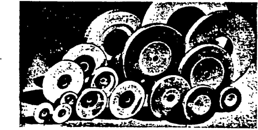
ILLUSTRATION No. 1
Examples of the various types of abrasive wheels included in this Code.
Organic wheels are wheels which are bonded by means of an organic material such as resin, rubber, shellac or other similar bonding agent.
Inorganic wheels are wheels which are bonded by means of inorganic material such as clay, glass, porcelain, sodium silicate, magnesium oxychloride, or metal. Wheels bonded with clay, glass, porcelain or related ceramic materials are characterized as “vitrified bonded wheels”.
1The term “Reinforced” as applied to grinding wheels shall define a class of organic wheels which contain strengthening fabric or filament.
The term “Reinforced” does not cover wheels using such mechanical additions as steel rings, steel cup backs or wire or tape winding. (See appendix A page 87 for additional protection devices.)
Explanatory Information
(NOT PART OF ANSI CODE)
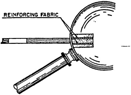
ILLUSTRATION No. 2.
Cross Section View One method of reinforcing organic bonded wheels.
The grinding surface or face is the surface of the grinding wheel upon which grinding is performed.
Explanatory Information
(NOT PART OF ANSI CODE)
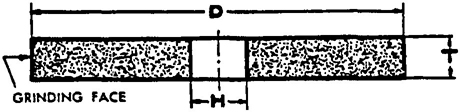
ILLUSTRATION No. 3
Arrow indicates grinding face.
A safety guard is an enclosure designed to restrain the pieces of the grinding wheel and furnish all possible protection in the event that the wheel is broken in operation. See section 4 page 27 for full description.
Explanatory Information
(NOT PART OF ANSI CODE)
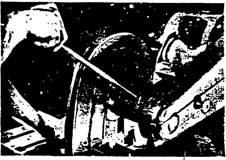
ILLUSTRATION No. 4
The safety guard affords operator protection in case of accidental breakage.
Wheel speed shall be computed from the free running speed of the machine spindle.
Explanatory Information
(NOT PART OF ANSI CODE)
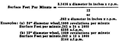
In Table 20 page 59, wheel speeds are classified in surface feet per minute (sfpm). Machine spindle speeds, however, are usually indicated in revolutions per minute. Therefore, one must have a clear understanding of how these two are related.
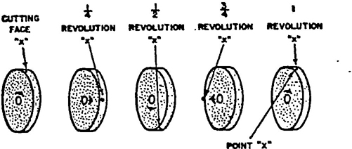
ILLUSTRATION No.5
Point ‘x’ has traveled a distance equal to the circumference of the wheel. (3.1415 x diameter)
Revolutions per minute (rpm) is the number of complete turns that a grinding wheel makes in one minute.
Surface feet per minute (sfpm) is the distance in feet any one abrasive grain on the peripheral surface of a grinding wheel travels in one minute.
Explanatory Information
(NOT PART OF ANSI CODE)
Surface feet per minute (sfpm) is the distance in feet any one abrasive grain on the cutting face travels in one minute. In Illustration No. 5 the point “x” on the cutting face travels, for every complete turn, a distance equal to the circumference, (3.1416 x diameter). Since the diameter of a grinding wheel is usually indicated in inches, it is necessary to divide the result by 12 in order to obtain the number of “surface feet per minute”.
Flanges are collars, discs or plates between which wheels are mounted and are referred to as adaptor, sleeve, or back up type. See section 5 page 42 for full description.
Steel rings may be molded into certain organic bonded grinding wheels in manufacture. Where used, such rings act mainly to add rigidity to the wheel as it approaches discard size and to help retain the pieces of the wheel should accidental breakage occur at stub size. See Appendix A page 87.
3Cup back, inserted type, round knurled and prong anchor bushings as shown in Illustration 6 are generally molded on types 6 and 11 organic bonded cup wheels.
Bushings of round, hexagonal, square or similar designs may be cemented or molded into the wheel holes. Including cone and plug wheels.
Adequate safety guards shall always be used with these wheels unless specifically excepted, by the code. See section 4 page 27 and Appendix A page 87.
Explanatory Information
(NOT PART OF ANSI CODE)
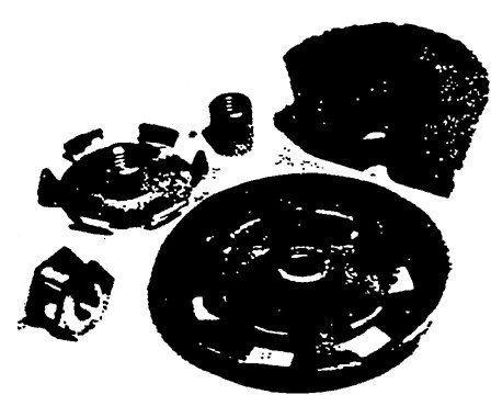
ILLUSTRATION No. 6
Hexagonal, prong anchor, round knurled and cup back bushings.
Reducing bushings are inserts or devices used to reduce the hole size in a grinding wheel so that it can be mounted correctly on a smaller diameter spindle. Reducing bushings shall be specifically designed, properly manufactured and fitted for use in grinding wheels as specified in paragraph 3.11, page 24. Minimum hole size as shown in Table 1 page 22 should not be violated nor should the bushing ends interfere with proper seating of the mounting flange or flanges. (See section 6 page 52.) Reducing bushings shall not be used to permit the operation of a grinding wheel in excess of its maximum operating speed.
Explanatory Information
(NOT PART OF ANSI CODE)
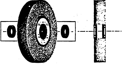
ILLUSTRATION No. 7
One type of reducing bushing commonly used to reduce a grinding wheel hole size.
Tape or wire winding as used on the periphery of cylinder, cup or segmented disc wheels helps to retain the pieces of the wheel should accidental breakage occur. See Appendix A page 87.
A chuck is a fixture designed to hold abrasive segments or certain types of grinding wheels and is mounted on a machine spindle or machine face plate.
Any individual, partnership, corporation or other form of enterprise which manufactures any kind of a abrasive wheel.
4Any individual, partnership, corporation or other form of enterprise which uses abrasive wheels and machines.
The precision grinding of the outer surface of any cylindrical work piece which is rotated by a regulating wheel and supported by a work blade.
Explanatory Information
(NOT PART OF ANSI CODE)
ILLUSTRATION No. 8
Typical through feed centerless grinding operation.
The sawing or grooving of any non-metallic material with an abrasive wheel.
5The slicing or parting of any material or part.
Explanatory Information
(NOT PART OF ANSI CODE)
ILLUSTRATION No.9
Cutting ordinary bar stock, using a resinoid bonded cutting-off wheel mounted on a dry, chopper type cutting-off machine.
The precision grinding of the outer surface of any cylindrical work piece which is supported at one or both ends.
The precision grinding of the inside surface of the hole in a work piece.
Explanatory Information
(NOT PART OF ANSI CODE)
ILLUSTRATION No.10
Internal grinding of a large bore cylinder.
The grinding of any material or part which is held in the operator’s hand.
Explanatory Information
(NOT PART OF ANSI CODE)
ILLUSTRATION No. 11
Off hand grinding on a double end pedestal grinder.
A grinding operation where the grinding machine is designed to be hand held and may be easily moved from one location to another.
Grinding operations performed by machines used to finish work parts to specified dimensions and finish requirements.
The shaping and/or sharpening of saw teeth by grinding.
Explanatory Information
(NOT PART OF ANSI CODE)
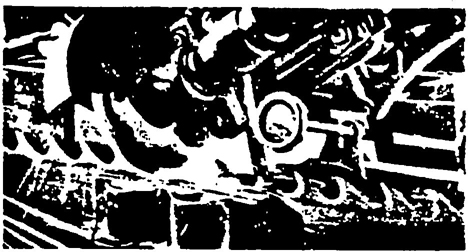
ILLUSTRATION No. 12
Sharpening the teeth (Saw Gumming) on a large band saw.
The grinding of a slot or groove in any material or part.
Grinding which removes relatively large amounts of material without regard to close tolerances or surface finish requirements.
The precision grinding of a plane surface.
The precision grinding or sharpening of various types of cutting tools.
Explanatory Information
(NOT PART OF ANSI CODE)
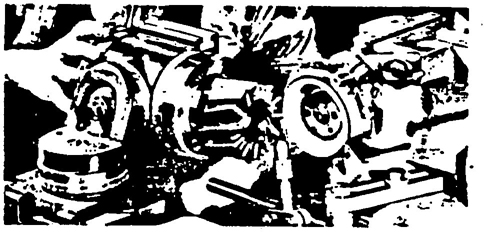
ILLUSTRATION No. 13
Grinding a shell end mill.
Removal, by grinding, of cement, mortar or other non-metallic jointing material.
Explanatory Information
(NOT PART OF ANSI CODE)
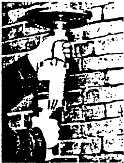
ILLUSTRATION No. 14
Tuck pointing using a reinforced organic bonded grinding wheel.
The following wheel shape definitions and limitations are safety code recommendations for general use and should be used wherever possible. Wheel dimensions or shapes differing from the standard recommendations below may be used on specific machines with the approval of the wheel manufacturer.
Explanatory Information
(NOT PART OF ANSI CODE)
When using non-standard wheels, it is often advisable for the user to consult the machine builder concerning special problems in mounting and guarding.
7Definition:
Type 1 straight wheels have diameter, thickness and hole size dimensions and should be used only on the periphery. Type 1 wheels shall be mounted between flanges, see section 5 page 42.
Limitation:
Hole dimension (H) should not be greater than two-thirds of wheel diameter dimension (D) for precision, cylindrical, centerless or surface grinding applications. Maximum hole size for all other applications should not exceed one-half wheel diameter. Inorganic wheels used in snagging operations should have a maximum hole size of not more than one quarter of the wheel diameter.
Explanatory Information
(NOT PART OF ANSI CODE)
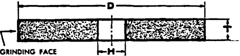
ILLUSTRATION No. 15
Type I — Straight Wheels Peripheral grinding wheel having a diameter, thickness and hole.
Definition:
Type 2 cylinder wheels have diameter, wheel thickness and rim thickness dimensions. Grinding is performed on the rim face only, dimension W. Cylinder wheels may be plain, plate mounted, inserted nut or of the projecting stud type.
Limitation:
Rim height, T dimension, is generally equal to or greater than rim thickness, W dimension.
Explanatory Information
(NOT PART OF ANSI CODE)
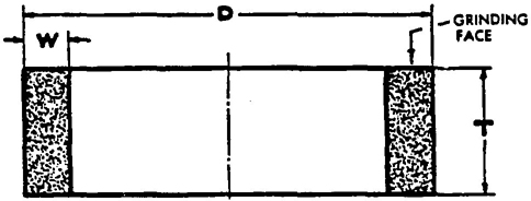
ILLUSTRATION No. 16
Type 2 Cylinder Wheel Side girnding wheel having a diameter, thickness and wall — wheel is mounted on the diameter
Definition:
Abrasive discs have diameter, thickness and hole size dimensions. They are used in a manner similar to type 2 cylinder wheels. (See section 3.13 page 25 and 3.14 page 26.)
Limitation:
Wheel thickness, T dimension, must be less than rim thickness, W dimension.
Explanatory Information
(NOT PART OF ANSI CODE)

ILLUSTRATION No. 17
Typical example of the various abrasive disc wheels
Definition:
Type 4 taper sided wheels have diameter, wheel thickness, grinding face thickness and hole size dimensions. Type 4 wheels have the same limitations on hole size and usage as type 1 wheels, definition 1.4.1 page 8.
Limitation:
Grinding face, thickness dimension U, must be equal to or greater than one half T dimension. J dimension shall be large enough to accommodate suitable flanges. If tapered safety flanges are used, J dimension and degree of taper required shall be determined by the wheel manufacturer.
Explanatory Information
(NOT PART OF ANSI CODE)
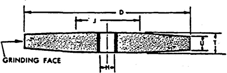
ILLUSTRATION No. 18
Type 4 — Taper Sided Wheels Peripheral grinding wheel having a diameter, wheel thickness grinding face thickness and hole size dimensions
Definition:
Type 5 recessed one side wheels have diameter, thickness and hole size dimensions and in addition also have a recess diameter and depth dimension. Type 5 wheels are subject to the same limitations of use and mounting as type 1 wheels definition 1.4.1 page 8 and section 6 page 52.
Limitation:
Type 5 wheels are subject to the same limitation of hole size as type 1 wheels definition 1.4.1 page 8. In addition recess depth, F dimension, should not exceed 50% of wheel thickness, T dimension, and diameter of recess, P dimension, shall be large enough to accommodate a suitable flange as recommended in section 5 page 42.
Explanatory Information
(NOT PART OF ANSI CODE)
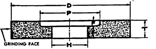
ILLUSTRATION No. 19
Type 5 — Wheel, recessed one side Peripheral grinding wheel having one side straight or flat and the opposite side recessed. Recessed wheels allow a wider faced grinding wheel to be used when the available mounting thickness (E) is less than the required overall thickness (T). The recess allows grinding clearance for the nut and flange.
Definition:
Type 6 cup wheels have diameter, thickness, hole size, rim thickness and back thickness dimensions, Grinding is always performed on rim face, W dimension.
Limitation:
Minimum back thickness, E dimension, should not be less than ¼ T dimension. In addition, when unthreaded hole wheels are specified, the inside flat, K dimension, must be large enough to accommodate a suitable flange, see flange recommendations, section 5 page 42.
Explanatory Information
(NOT PART OF ANSI CODE)
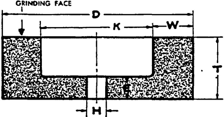
ILLUSTRATION No. 20
Type 6 — Straight-cup Wheel Side grinding wheel having a diameter, thickness and hole with one side straight or flat and the opposite side recessed. This type, however, differs from Type 5 in that the grinding is performed on the wall of the abrasive created by the difference between the diameter of the recess and the outside diameter of the wheel. Therefore, the wall dimension “W” takes precedence over the diameter of the recess as an essential intermediate dimension to describe this shape type.
Definition:
Type 7 double recessed wheels have diameter, thickness and hole size dimensions and in addition also have recess diameters and depth dimensions. Type 7 wheels are subject to the same limitations of use and mounting as type 5 wheels, definition 1.4.5 page 9 and section 6 page 52.
Limitation:
Type 7 wheels are subject to the same limitation of hole size as type 1 wheels, section 1.4.1 page 8. In addition the combined depths of recess, F and G dimensions, should not exceed 50% of wheel thickness, T dimension.
Explanatory Information
(NOT PART OF ANSI CODE)
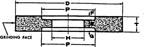
ILLUSTRATION No. 21
Type 7 — Wheel, recessed two sides Peripheral grinding wheels having both sides recessed to allow grinding clearance for both flanges or recessed so that unusually wide faced wheels may be mounted when the available mounting thickness (E) is less than the overall thickness (T)
Definition:
Type 11 flaring cup wheels have double diameter dimensions D and J, and in addition have thickness, hole size, rim and back thickness dimensions. Grinding is always performed on rim face, W dimension. Type 11 wheels are subject to all limitations of use and mounting listed for type 6 straight sided cup wheels definition 1.4.6 page 9 and section 6 page 52.
Limitation:
Minimum back thickness, E dimension, should not be less than ¼ T dimension. In addition when unthreaded hole wheels are specified the inside flat, K dimension, shall be large enough to accommodate a suitable flange, see flange recommendations section 5 page 42.
Explanatory Information
(NOT PART OF ANSI CODE)
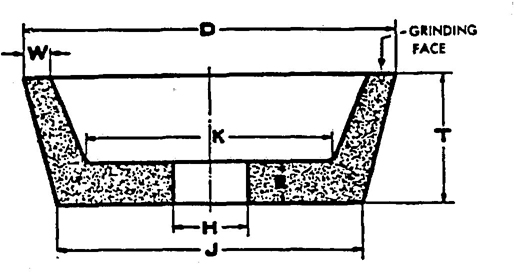
ILLUSTRATION No. 22
Type 11 — Flaring-cup Wheel Side grinding wheel having a wall flared or tapered outward from the back. Wall thickness at the back is normally greater than at the grinding face (W).
Definition:
Type 12 dish wheels have diameter, thickness, rim thickness and back thickness dimensions. In addition type 12 wheels always have a face thickness, U dimension. Grinding may be performed on both A and U dimensions.
Limitation:
Minimum back thickness, E dimension, should be equal to or greater than ½ wheel thickness, T dimension. If unthreaded hole wheels are specified K dimension shall be large enough to accommodate a suitable flange, see flange recommendations section 5 page 42.
Explanatory Information
(NOT PART OF ANSI CODE)
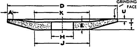
ILLUSTRATION No. 23
Type 12 — Dish Wheel Side grinding wheel known as a dish, differing from a Type 12 always has a “U” dimension. The “W” dimension of a type 11 becomes that “A” of a type 12. The grinding may be performed on the “U” face.
Definition:
Type 13 saucer wheels have diameter, thickness, hole size and back thickness dimensions. Grinding shall be performed on wheel periphery, U dimension, only.
Limitation:
Where unthreaded hole wheels are specified, J and K dimensions shall be large enough to accommodate suitable flanges, see section 5 page 42. In addition, wheel thickness shall be uniform throughout, U dimension should always equal E dimension.
Explanatory Information
(NOT PART OF ANSI CODE)
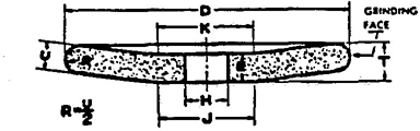
ILLUSTRATION No. 24
Type 13 — Saucer Wheel Peripheral grinding wheel known as a saucer, differing from a Type 12 in that the cross-section is equal throughout (U = E).
The face is always half-round with 
Definition:
Type 16 cones have a curved side with a nose radius. Type 17 cones have straight sides with or without a nose radius. Types 18 and 18R plug wheels are cylindrical in shape with either a square or curved grinding end. Type 19 cone wheels are a combination of cone and plug type shapes and are usually specified where base dimension D in a type 17 cone would not provide an adequate cross section of abrasive. All types of cone and plug wheels are manufactured with blind hole threaded bushings and may be used on all surfaces except that flat mounting surface D.
Limitation:
Cone and plug type wheels are mounted by being screwed onto a threaded machine spindle so that surface D seats firmly against an unrelieved, flat back-up flange. (See section 3.12 page 24.) It is recommended that the maximum size or mass of the above cones and plugs be not greater than that of a 3” diameter by 5” long type 18 plug wheel.
Explanatory Information
(NOT PART OF ANSI CODE)
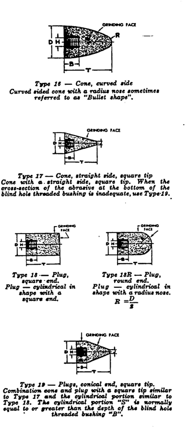
ILLUSTRATION No. 25
Various types of cone and plug wheels.
Definition:
[Illegible Text Omitted on Page 12] 20 through 26 relieved and/or recessed [Illegible Text Omitted on Page 12] have diameter, thickness, hole size, re-[Illegible Text Omitted on Page 12] diameter and depth dimensions and in [Illegible Text Omitted on Page 12] may be concaved on one or both sides. [Illegible Text Omitted on Page 12] 20 through 26 wheels are subject to the [Illegible Text Omitted on Page 12] limitations of use and mounting as type [Illegible Text Omitted on Page 12] definition 1.4.5 page 9 and section 6 [Illegible Text Omitted on Page 12] 52.
Limitation:
[Illegible Text Omitted on Page 12] relief depths shall be considered as [Illegible Text Omitted on Page 12] and added to straight recess depth or [Illegible Text Omitted on Page 12] for determination of total wheel recess [Illegible Text Omitted on Page 12]. Total recess depths should not exceed [Illegible Text Omitted on Page 12] of wheel thickness, T dimension.
Explanatory Information
(NOT PART OF ANSI CODE)
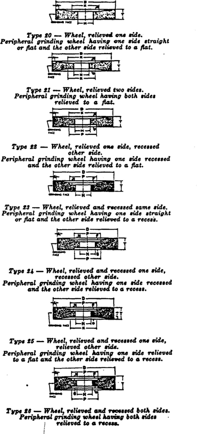
ILLUSTRATION No. 26
Various types of relieved and/or recessed wheels.
Definition:
Types 27 and 28, depressed center wheels, have diameter, thickness and hole size dimensions. Both types are reinforced, organic bonded wheels having off-set hubs which permit side and peripheral grinding operations without interference with the mounting. Type 27 wheels are manufactured with flat grinding rims permitting notching and cutting operations. Type 28 wheels have saucer shaped grinding rims.
Limitation:
Special supporting, back adaptor and inside flange nuts are required for the proper mounting of these types of wheels, see section 6.15 page 56.
Mounts which are affixed to the wheel by the manufacturer may not require and inside nut and shall not be reused.
Explanatory Information
(NOT PART OF ANSI CODE)
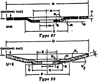
ILLUSTRATION NO. 27
Types 27 and 28 — Wheels, depressed center. Peripheral grinding wheel having an offset center and used on right angle head portable grinders. Grinding may also be done on the side of the wheel.
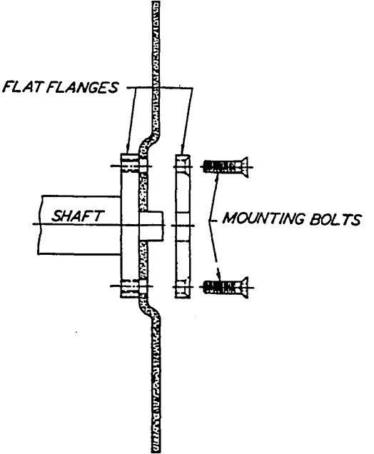
ILLUSTRATION NO. 28
Type 27A wheel showing typical mounting details.
Type 27A depressed center, cutting-off wheels have diameter, thickness and hole size dimensions. They are reinforced, organic bonded, off-set hub type wheels, usually 16” diameter and larger, specially designed for use on cutting-off machines where mounting nut or outer flange interference cannot be tolerated.
Limitations
See section 5.1 page 42 and illustration 28 for mounting details.
13Definition:
Cutting off wheels have diameter, thickness and hole size dimensions and are subject to all limitations of mounting and use listed for type 1 wheels, definition 1.4.1 page 8 and section 6 page 52. They may be steel centered, diamond abrasive or organic bonded abrasive of the plain or reinforced type.
Limitation:
Cutting off wheels are recommended only for use on specially designed and fully guarded machines and are subject to the following maximum thickness and hole size limitations.
| Wheel Diameter | Max. Thickness |
|---|---|
| 6" and smaller | 3/16 " |
| Larger than 6" to 12" | ¼" |
| Larger than 12" to 23" | 3/8 " |
| Larger than 23" | ½" |
Maximum hole size for cutting-off wheels should not be larger than ¼ wheel diameter.
Explanatory Information
(NOT PART OF ANSI CODE)
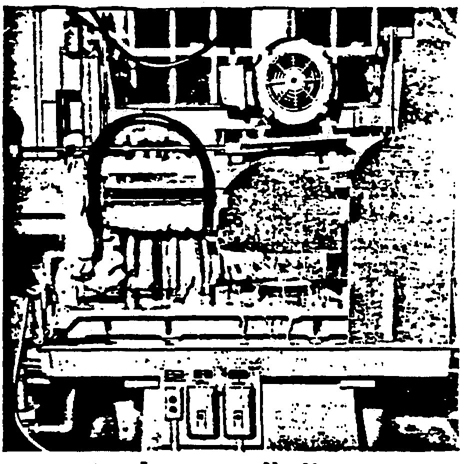
ILLUSTRATION No. 29
A wet machine with horizontal movement for slabbing.
Definition:
Coping wheels are peripheral cutting wheels, and have diameter, thickness and hole size dimensions. They may be metal or organic bonded, solid or steel centered, and are subject to the same limitations of use and mounting as type 1 wheels, definition 1.4.1 page 8 and section 6 page 52.
Limitation:
Coping wheels are recommended for use only on specially designed and fully guarded machines.
Explanatory Information
(NOT PART OF ANSI CODE)
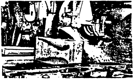
ILLUSTRATION No. 30
Slotting a block of marble to contour using a coping wheel.
Definition:
Tuck pointing wheels, usually type 1, reinforced organic bonded wheels have diameter, thickness and hole size dimension. They are subject to the same limitations of use and mounting as type 1 wheels definition 1.4.1 page 8 and section 6 page 52.
Limitation:
Wheels used for tuck pointing should be reinforced, organic bonded, (See paragraph 4.5.1, Exception B, page 32.)
Explanatory Information
(NOT PART OF ANSI CODE)
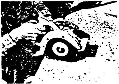
ILLUSTRATION No. 31
Tuck pointing granite using a straight resinoid reinforced wheel.
Definition:
Mounted wheels, usually 2" diameter or smaller, and of various shapes, may be either organic or inorganic bonded abrasive wheels. They are secured to plain or threaded steel mandrels.
Limitation:
See section 10 page 69 for safe operation and speeds for mounted wheels.
Explanatory Information
(NOT PART OF ANSI CODE)
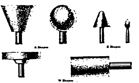
ILLUSTRATION No. 32
Typical examples of grinding wheels knows as mounted wheels.
Threaded hole cup wheels types 6 and 11 are designed for use on vertical, right angle head, or flexible shaft portable grinders. They have one central threaded bushing, securely anchored in place. They are mounted by being screwed onto a threaded machine spindle so that the wheel back seats firmly against an unrelieved flat back flange.
Limitation:
Threaded hole cup wheel mounting should not be used with wheels larger 6” diameter. Back fianges used in mounting threaded hole cup wheels shall be flat and unrelieved.
Explanatory Information
(NOT PART OF ANSI CODE)
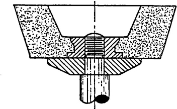
ILLUSTRATION NO. 33
A cup wheel with an inserted bushing. Note the bushing and abrasive are in uniform contact with the back flange.
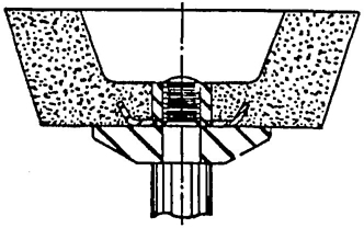
ILLUSTRATION NO. 33A
A cup wheel with a prong anchor bushing. Note the bushing and abrasive are in uniform contact with the back flange.
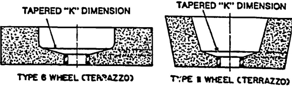
ILLUSTRATION NO. 34
Typical examples of modified types 6 and 11 wheels (terrazzo) showing taperred K dimensions.
Some type 6 & 11 cup wheels used in the terrazzo trade have tapered K dimensions to match a special tapered flange furnished by the machine builder.
Limitation:
These wheels shall be mounted only with a special tapered flange.
15All grinding wheels are breakable and therefore care shall be exercised in handling and storage to prevent damage. The following rules, which are based on experience, shall always be observed.
(a) Handle wheels carefully to prevent dropping or bumping.
(b) Do not roll wheels (hoop fashion).
(c) Use trucks or other suitable conveyances, which provide support and protection in transporting all wheels which cannot be carried by hand.
(d) Place wheels carefully on a shelf or rack or in bins, boxes or drawers.
Explanatory Information
(NOT PART OF ANSI CODE)
All grinding wheels must be handled carefully.
It should be realized that grinding wheels are necessarily manufactured in varying strengths to grind properly.
Some grinding wheels are stronger than others, but all grinding wheels can be broken by mishandling.
Suitable racks, bins, drawers or boxes shall be provided to store the various types of wheels used. (See Fig. 1,2 and 3 pages 17–18.)
Wheels shall not be stored subject to:
(a) Exposure to high humidity, water or other liquids.
(b) Freezing temperature.
(c) Any temperature low enough to cause condensation on the wheels when moving them from storage to an area of higher temperature.
Explanatory Information
(NOT PART OF ANSI CODE)
Grinding wheels must be protected while awaiting use. Wheel storage should be arranged to allow for removal of wheels without disturbing or damaging other wheels. Storage and records should also be set up to allow for wheel use on a rotational basis so that wheels will be in storage a minimum length of time. This minimizes the possibility of damage from lengthy storage. Such suitable storage should be available for partly used wheels as well as new wheels.
162.2 Storage
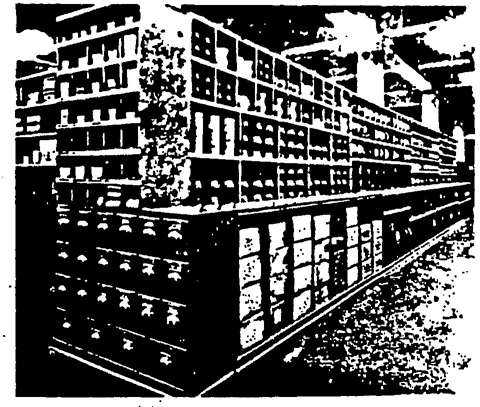
FIGURE NO. 1
A well-designed grinding wheel storage area used by a large industrial plant.
Explanatory Information
(NOT PART OF ANSI CODE)
Grinding wheel storage racks should be designed, constructed and located to fit the needs of the user. The following factors should be considered:
Location
All grinding wheels should be stored in a dry area in rooms not subject to extreme temperature changes since some bonds may be affected by excessive humidity, dampness and extreme temperature differentials. Racks should be located as near as practical to the grinding location, but never where there is danger of damage from passing trucks, crane handling or excessive vibration.
FIGURE NO. 2
This drawing illustrates a rack design which is suitable for handling a wide variety of grinding wheels.
2.2 Storage
FIGURE NO. 3
The various sizes and shapes of wheels are located in the racks so that they are easily accessible and protected from damage.
Explanatory Information
(NOT PART OF ANSI CODE)
Storage Methods
The racks, bins or drawers should be constructed so that each of the various types of wheels can, be stored in an orderly and safe manner. (See Fig. 2 page 17.) Wheel selection should be possible with a minimum of handling.
The selection of racks, bins, boxes or drawers for storage depends on the size and type of wheels. The following suggestions should be considered.
Thin organic bonded wheels such as those used for cutting-off should be laid flat on a flat surface of steel or similar rigid material away from excessive heat or moisture to prevent warpage. Not even blotters should be allowed between stacked thin wheels. If thin wheels are supplied with blotters attached, suitable separators should be used to preserve flatness.
Straight or tapered wheels (Types 1, 4, 5, 7, 13, 20, 21, 22, 23, 24, 25 and 26) of appreciable thickness are best supported in racks (see Fig. 2 page 17). Preferably the racks should provide a cushioned two-point cradle support to prevent the wheels from rolling. Partitions are helpful in facilitating wheel selection with a minimum of handling.
Cylinder wheels (Type 2), large straight cup wheels (Type 6), large dish wheels (Type 12) and large saucer wheels (Type 13) may be stacked on flat sides with some form of cushioning material between them; or they may be stored on edge like large straight wheels.
Flaring cup wheels (Type 11) are best stored as Illustrated in Fig. 2 page 17 to prevent chipping of edges.
Small wheels (approximately 4 inches or less in diameter). except flaring cup wheels (Type 11), are often stored in boxes, bins, or drawers.
Immediately after unpacking, all wheels shall be closely inspected to make sure that they have not been damaged from handling, shipping or other causes. As an added precaution, wheels should be tapped gently with a light non-metallic implement, such as the handle of a screw driver for light wheels, or a wooden mallet for heavier wheels. If they sound cracked (dead), they shall not be used. This is known as the “Ring Test”. (see Figs. 4 and 5 page 19.)
Explanatory Information
(NOT PART OF ANSI CODE)
The first inspection should be made on the original shipping container. If there is visible evidence of damage to the container, special care must be used in the inspection of the wheels.
182.3 Inspection
Wheels must be dry and free from sawdust when applying the ring test, otherwise the sound will be deadened. It should also be noted that organic bonded wheels do not emit the same clear metallic ring as do vitrified and silicate wheels.
FIGURE NO. 4 FIGURE NO. 5
“Tap” wheels about 45 degrees each side of the vertical center line and about 1 or 2 inches from the periphery as indicated by the spots in Fig. 4 and Fig. 5.
Then rotate the wheel 45 degrees and repeat the test.
A sound and undamaged wheel will give a clear metallic tone. If cracked, there will be a dead sound and not a clear “ring.”
Explanatory Information
(NOT PART OF ANSI CODE)
“Ring Test”
If the wheel is not too heavy, it may be suspended from the hole on a small pin or the finger. (See III. No. 35.) Heavier wheels may be allowed to rest in a vertical position on a clean, hard floor.
“Tap” the wheel gently with a non-metallic implement such as a wooden screw driver handle for light wheels and a wooden mallet for heavy wheels. The best spot to “tap” a wheel for the ring test is about 45 degrees either side of the vertical center line and about 1 or 2 inches from the periphery. (See Figs. 4 and 5.)

ILLUSTRATION NO. 35
If struck directly along the vertical center line, the “ring,”, even in a sound wheel, is sometimes muffled and may give the erroneous impression that the wheel is cracked. This is especially true with large wheels which are supported on the floor when conducting this test. (See Fig. 5.) It is sometimes noticeable also when the wheel is suspended from the hole. It is recommended that the test be repeated after rotating the wheel 45 degrees to the right or left.
Repeat this “ring test” immediately before mounting-either a new or used wheel on a machine, especially if the wheel has been in storage or out of service for a considerable time. In making this test it must be realized that wheels bonded with organic material do not give forth the same clear metallic sound as do vitrified and silicate wheels. Also wheels must be dry and free from sawdust when applying the test, otherwise the sound will be deadened.
Comparison of the sound with other wheels of the same lot and specification will allow rejection of any wheel with a suspiciously different ring before use.
19It shall be the machine manufacturer’s responsibility to design, and the user’s responsibility to maintain, his machines for safe operating condition.
The following areas are important to fulfill these obligations.
Explanatory Information
(NOT PART OF ANSI CODE)
Grinding is a safe operation under normal conditions. Severe stresses can be set up in the wheel if established safe operating practices are not maintained. Only machines designed for the required spindle speed with suitable bearings to take the pressure and thrust of the grinding operation are recommended.
Proper maintenance of grinding machines is very important to insure safe operation. Grinding machine maintenance should be performed only by qualified personnel.
Grinding machines shall be equipped with safety guards in conformance with the requirements covered in section 4 page 27.
Explanatory Information
(NOT PART OF ANSI CODE)
Safety guards must be used on grinding machines to insure protection in case of an accidental wheel breakage. (See section 4.1 page 27 for exceptions.)
Grinding machines should be supplied with sufficient power to maintain the rated spindle speed under all conditions of normal operation.
Explanatory Information
(NOT PART OF ANSI CODE)
If the grinding wheel speed is reduced materially under normal grinding pressure, its cutting ability is decreased and excessive heat and pressure often result. Adequate power will avoid this hazard.
Stationary machines used for dry grinding should have provision made for connection to an exhaust system.
For detailed recommendations. Reference is made to “American National Standard For Ventilation Control of Grinding, Polishing and Buffing Operations (Z43.1).” Copies may be obtained from The American National Standards Institute.
Explanatory Information
(NOT PART OF ANSI CODE)
ILLUSTRATION No. 36
Note the excellent provisions employed to exhaust grinding dust.
Table 1 page 22 shows the minimum diameters of spindles which should be used for wheels of various sizes. It applies to machines where wheels are not mounted between bearings. The use of heavier spindles than those listed in this table is often desirable.
Explanatory Information
(NOT PART OF ANSI CODE)
Standard machine design generally conforms to the minimum spindle diameter requirements in Table 1 page 22. Investigation has shown that requests for wheels with undersize holes often result from the desire to use larger diameter wheels than were originally intended for the machine.
Grinding machines shall be equipped with flanges in accordance with the requirements listed in section 5 page 42.
Explanatory Information
(NOT PART OF ANSI CODE)
Proper selection, use and maintenance of flanges are all essential factors in the safe use of grinding wheels. See section 5 page 42.
On offhand grinding machines (see section 1.3.6 page 6), work rests shall be used to support the work. They shall be of rigid construction and designed to be adjustable to compensate for wheel wear.
Work rests shall be kept adjusted closely to the wheel with a maximum opening of ⅛ʺ to prevent the work from being jammed between the wheel and the rest, which may cause wheel breakage. The work rest shall be securely clamped after each adjustment. The adjustment shall not be made with the wheel in motion.
Explanatory Information
(NOT PART OF ANSI CODE)
ILLUSTRATION No. 37
This floor stand grinder has a work rest which is properly adjusted. Note the provisions for work-rest adjustment.
Grinding machines should be provided with a means of limiting the diameter of wheel which can be mounted. The safety guard is generally satisfactory for this purpose on single speed machines.
On variable speed machines, the speed shifting device should be connected with an adjustable guard or another diameter limiting device to prevent the mounting of a wheel which might run at higher than the recommended surface speed.
Explanatory Information
(NOT PART OF ANSI CODE)
On variable speed machines, a positive mechanical or manual regulation check should be maintained to avoid overspeeding another or full size wheel after the original wheel stub has been removed.
21| Thickness of Wheel, Inches | |||||||||||||||||||
|---|---|---|---|---|---|---|---|---|---|---|---|---|---|---|---|---|---|---|---|
| Diam- eter of Wheel |
Less Than 1/4″ |
¼ | ⅔ | ½ | ⅝ | ¾ | 1 | 1¼ | 1½ | 2 | 2¼ | 2½ | 2¾ | 3 | 3¼ | 3½ | 4 | 5 | 6 |
| ←Diameter of Spindle — Inches→ | |||||||||||||||||||
| 2 3 4 5 |
⅛ ¼ [Illegible Text Omitted on Page 22] ⅜ |
⅛ ¼ [Illegible Text Omitted on Page 22] ⅜ |
[Illegible Text Omitted on Page 22] ¼ ⅜ ⅜ |
[Illegible Text Omitted on Page 22] ⅜ ⅜ ½ |
¼ ⅜ ⅜ ½ |
¼ ⅜ ⅜ ½ |
⅜ ⅜ ⅜ ½ |
⅜ ⅜ ½ ½ |
⅜ ⅜ ½ ½ |
⅜ ½ ½ ½ |
⅜ ½ ½ ⅝ |
½ ½ ½ ⅝ |
½ ½ ⅝ ⅝ |
½ ½ ⅝ ⅝ |
½ ½ ⅝ ⅝ |
½ ½ ⅝ ¾ |
½ ⅝ ⅜ ¾ |
⅝ ⅝ ¾ ¾ |
⅜ ⅜ ¾ ¾ |
| 6 7 8 |
½ ½ ½ |
½ ½ ½ |
½ ½ ½ |
½ ½ ½ |
½ ½ ½ |
½ ½ ⅝ |
½ ½ ⅝ |
½ ⅝ ⅝ |
½ ⅝ ⅝ |
⅝ ⅝ ¾ |
¾ ¾ ¾ |
¾ ¾ ¾ |
¾ ¾ ¾ |
¾ ¾ 1 |
¾ ¾ 1 |
¾ ¾ 1 |
¾ 1 1 |
¾ 1 1 |
1 1 1 |
| 9 10 12 |
⅝ ⅝ ⅝ |
⅝ ⅝ ¾ |
⅝ ⅝ ¾ |
⅝ ⅝ ¾ |
⅜ ⅝ ¾ |
⅝ ¾ ¾ |
⅝ ¾ ¾ |
¾ ¾ ¾ |
¾ ¾ 1 |
¾ ¾ 1 |
1 1 1 |
1 1 1 |
1 1 1 |
1 1¼ 1¼ |
1 1¼ 1¼ |
1 1¼ 1¼ |
1¼ 1¼ 1¼ |
1¼ 1¼ 1½ |
1¼ 1¼ 1½ |
| 14 16 18 |
¾ ⅞ ⅞ |
¾ 1 1 |
¾ 1 1 |
¾ 1 1 |
¾ 1¼ 1¼ |
1 1¼ 1¼ |
1 1¼ 1¼ |
1 1¼ 1¼ |
1 1¼ 1¼ |
1 1¼ 1¼ |
1 1¼ 1½ |
1¼ 1¼ 1½ |
1¼ 1¼ 1½ |
1¼ 1½ 1½ |
1¼ 1½ 1½ |
1¼ 1½ 1½ |
1½ 1½ 1¾ |
1½ 1½ 1¾ |
1½ 1¾ 1¾ |
| 20 24 26 |
1 1 1 |
1 1 1 |
1 1 1 |
1 1 1 |
1¼ 1¼ 1¼ |
1¼ 1¼ 1¼ |
1½ 1½ 1½ |
1½ 1½ 1½ |
1½ 1½ 1½ |
1½ 1½ 1½ |
1½ 1½ 1¾ |
1½ 1½ 1¾ |
1½ 1½ 1¾ |
1½ 1¾ 1¾ |
1¾ 1¾ 2 |
1¾ 1¾ 2 |
1¾ 2 2 |
1¾ 2 2 |
2 2 2 |
| 30 36 |
1 1½ |
1½ 1¾ |
1½ 1¾ |
1½ 1¾ |
1½ 1¾ |
1½ 1¾ |
1½ 2 |
1½ 2 |
1¾ 2 |
1¾ 2 |
1¾ 2 |
1¾ 2 |
2 2¼ |
2 2¼ |
2 2¼ |
2 2½ |
2¼ 2½ |
2¼ 2¾ |
2¼ 2¾ |
| 40 44 48 |
1¾ 2 2¼ |
2 2½ 2¾ |
2 2½ 2¾ |
2 2½ 2¾ |
2 2½ 2¾ |
2 2¾ 2¾ |
2¼ 2¾ 2¾ |
2¼ 2¾ 3 |
2¼ 2¾ 3 |
2¼ 3 3 |
2½ 3 3½ |
2½ 3 3½ |
2½ 3 3½ |
2½ 3 3½ |
2¾ 3½ 3½ |
2¾ 3½ 3½ |
2¾ 3½ 3½ |
2¾ 3½ 3½ |
2¾ 3½ 4 |
| 53 60 72 |
2½ 2¾ 3 |
3 3½ 3½ |
3 3½ 3½ |
3 3½ 3½ |
3 3½ 3½ |
3½ 3½ 3½ |
3½ 3½ 3½ |
3½ 4 4 |
3½ 4 4 |
3½ 4 4 |
3½ 4 4½ |
3½ 4 4½ |
3½ 4 4½ |
3½ 4 4½ |
4 4 4½ |
4 4½ 5 |
4 4½ 5 |
4 5 6 |
4½ 5 6 |
| NOTE: For speeds exceeding those listed in Table 20 page 59, for unusually severe operations and for wheels with heavy mountings (such as bolted-on abra-[Illegible Text Omitted on Page 22]), the spindle sizes shown in the above table may not be [Illegible Text Omitted on Page 22] asmuch as the proper spindle size is dependent upon many factors, [Illegible Text Omitted on Page 22] design of the machine, type of bearings, quality of materials, [Illegible Text Omitted on Page 22] and application of wheel, a simple table is not practicable. [Illegible Text Omitted on Page 22] larger than specified by the machine manufacturer should not be used. | |||||||||||||||||||
If wheels or flanges are secured by means of a central spindle nut, the direction of the thread shall be in such relation to the direction of rotation that the nut will tend to tighten as the spindle revolves. The following rule will assist in determining the proper relationship:
“To remove the nut it must be turned in the direction that the spindle revolves when the wheel is in operation.”
Explanatory Information
(NOT PART OF ANSI CODE)
On double-end floor stands and bench grinders one end of the spindle must therefore have a right hand thread and the other a left hand thread. When re-assembling such machines after repairs, care shall be used to properly replace the spindle, with respect to direction of threads.
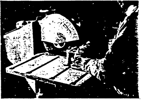
ILLUSTRATION No. 38
The direction of rotation of the cutting-off wheel is indicated by the arrow on the guard. This is also the direction the nut must be turned for removal.
If wheels are mounted by means of a central spindle nut and flanges, two conditions shall be maintained:
Explanatory Information
(NOT PART OF ANSI CODE)
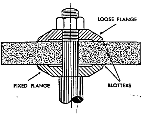
ILLUSTRATION No. 39
The spindle is of sufficient length to accommodate the wheel and flanges.
Grinding wheels shall fit freely on the spindle (wheel sleeves or adaptors) and remain free under all grinding conditions.
To accomplish this, the spindle or wheel mount shall be made to nominal (standard) size plus .000 minus .002 inches. The wheel hole shall be made suitably oversize to assure safety clearance under the conditions of operating heat and pressure.
Explanatory Information
(NOT PART OF ANSI CODE)
To avoid rupturing pressure in the wheel hole, the diameter of the spindle or wheel mount shall be kept within the limits of plus zero, minus. .002 inches. The hole in the wheel must be suitably oversize so that the wheel fits freely but not loosely under all operating conditions, to allow for expansion of the wheel spindle or mount caused by the heat of operation.
Machines on which threaded hole wheels are mounted shall be provided with spindles which are so threaded as to allow the wheel to be screwed firmly and flat against the back flange. (See Figs. 6 and 7.)
The back flange shall be flat, unrelieved, securely fastened and square to the spindle axis. (See III. 40.) The fixed back flange shall be of sufficient diameter to insure proper support to the wheel. (See Table 13 page 48.)
The direction of the thread shall be such that to remove the wheel it must be turned in the same direction that it rotates when in use.
If threaded hole wheels are of cone or plug shape with blind holes, the length of the spindle and the depth of the hole shall be such that the end of the spindle shall not touch the bottom of the wheel hole.
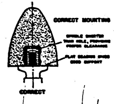
FIGURE No. 6
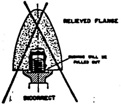
FIGURE No. 7
Explanatory Information
(NOT PART OF ANSI CODE)
A relieved back flange shall not be used. If made with a relief, the flange will cause the bushing to be pulled out of the wheel, as shown in Illustration 40.
The fixed back flange should be perfectly flat and heavy enough to prevent distortion.
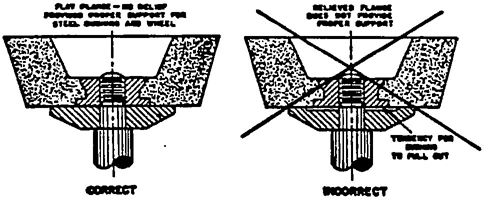
ILLUSTRATION No. 40
Unrelieved and relieved flange
If the spindle stops quickly when power is shut off, the energy stored in the spinning wheel may cause the wheel to unscrew from the spindle and “Spin Off” the machine.
To help prevent “spinning off” the threads on the machine spindle should be maintained in good condition and the wheel should be held in contact with the work piece until the wheel has stopped.
24Machines on which inserted nut wheels are mounted shall be provided with a steel disc wheel (machine face plate) of approximately the same diameter as the wheel, and of sufficient thickness to provide necessary support. Minimum steel disc wheel (machine face plate) thickness for disc grinders are shown in Table 2.
| Diameter Inches | Minimum Thickness Inches |
|---|---|
| 8 to 14 inclusive | ½ |
| 15 to 18 inclusive | ½ |
| 19 to 26 inclusive | ¾ |
| 27 to 36 inclusive | ⅞ |
| 37 to 40 inclusive | 1 |
| 41 to 72 inclusive | 1 ¼ |
Screw holes in steel disc wheel (machine face plate) should be accurately located to match the threaded holes in the inserted nuts in the wheel, and shall be large enough so that the screws will not bind.
Dimension X (Fig. 8) shall be uniform for all holes so that screws can be used interchangeably.
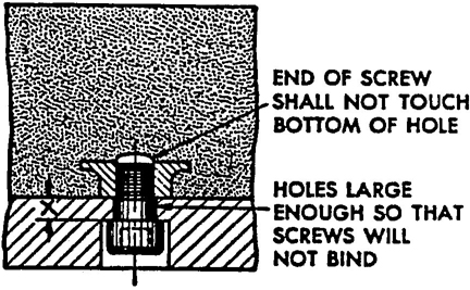
FIGURE NO.8
Screws shall be of sufficient length to properly engage the threads in the inserted nuts, yet not so long that there will be any possibility of the ends touching bottom.
Explanatory Information
(NOT PART OF ANSI CODE)
The following illustrations (Nos. 41, 42 and 43) will serve to clarify the differences which exist between the three types of mountings for abrasive discs, i.e. the inserted nut type, the inserted washer type, and the projecting stud type.
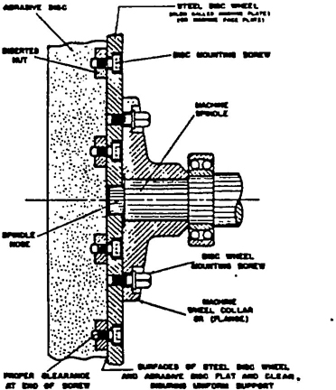
ILLUSTRATION No. 41
Inserted nut type abrasive disc
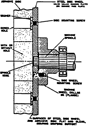
ILLUSTRATION No. 42
Inserted washer type abrasive disc.
3.13 Mounting of Abrasive Discs (Inserted Nut, Inserted Washer and Projecting Stud Type)
Steel disc wheels (machine face plates) shall be flat concentric and at a 90° angle as mounted to the machine spindle.
Explanatory Information
(NOT PART OF ANSI CODE)
Machine face plate and the mounting surface of the abrasive disc shall be maintained true, flat and clean. This is the user’s responsibility.
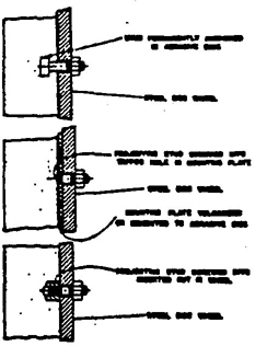
ILLUSTRATION No. 43
Various methods of mounting projecting stud or stud mounted type abrasive discs.
If the plates attached to the wheel are as thick or thicker than shown in Table 2 page 25, there are no special requirements as to the diameter and thickness of the steel disc wheel (machine face plate) on the machine.
If the plates attached to the wheel are thinner than shown in Table 2 page 25, the machine shall be equipped with a steel disc wheel (machine face plate) of sufficient diameter and thickness to provide adequate additional support. Minimum specifications are given in Table 3 for disc grinders.
| Abrasive Disc Diameter D (Inches) | Minimum Thickness Pt (Inches) |
|---|---|
| 12 and smaller | ¾ |
| 14 to 16 inclusive | ½ |
| 17 to 18 inclusive | ⅝ |
| 19 to 26 inclusive | ½ |
| 27 to 36 inclusive | ⅞ |
Explanatory Information
(NOT PART OF ANSI CODE)
A typical method of mounting a plate mounted type wheel is shown in Illustration No. 44. Note the additional reinforcement given the abrasive disc and the mounting plate by the steel disc wheel (machine face plate).
Even when plate mounted wheels are used, the machine face plate (steel disc wheel) should be the full diameter of the wheel where possible. The original thickness of the machine face plate should be thicker than minimum in Table 3 to allow for remachining to correct for wear.
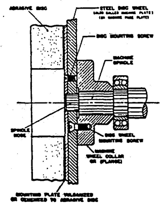
ILLUSTRATION No. 44
Plate mounted type wheels.
All abrasive wheels shall be used only on machines provided with Safety Guards as defined in the following paragraphs of this section.
Exceptions: This requirement shall not apply to the following classes of wheels and conditions.
(1) Wheels used for internal work while with in the work being ground.
(2) Mounted wheels used in portable operations (see definition Sec 1.4.18 page 15) 2 inches and smaller in diameter.
(3) Types 16, 17, 18, 18R and 19 cones and plugs and threaded hole pot balls where the work offers protection.
Note: For additional forms of operator protection see Appendix A page 87.
Explanatory Information
(NOT PART OF ANSI CODE)
Exceptions to the use of safety guards are based on the impossibility of using these classes of wheels with conventional guards in place. In these cases, the work often forms a guard and the mass of the wheel is small. Face protection is particularly important when using this class of wheel.
Cup wheels (Types 6 and 11) shall be protected by
(a) Safety Guards as specified in Sections 4.1 page 27 to 4.10 page 37 inclusive or
(b) Band Type Guards as specified in Sections 4.11 page 40 and 4.12 page 40 or
(c) Special “Revolving Cup Guards” which mount behind the wheel and turn with it. They shall be made of steel or other material with adequate strength and shall enclose the wheel sides upward from the back for ⅓ of the wheel thickness. The mounting features shall conform with all Code regulations. (See section 6 page 52.)
It is necessary to maintain clearance between the wheel side and the guard. This clearance shall not exceed 1/16 inch.
(d) Some other form of guard that will insure as good protection as that provided by the guards specified in (a) and (b) and (c).
Explanatory Information
(NOT PART OF ANSI CODE)
Cup wheels are available with either a threaded or unthreaded hole. Guards are available for each of these types. The following illustrations Nos. 45, 46 and 47, show the typical types manufactured. Each is shown mounted in conjunction with a guard.
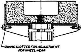
ILLUSTRATION No. 45
Type 6 cup wheel showing band type guard.
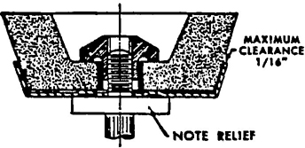
ILLUSTRATION No. 46
An unthreaded hole cup wheel and revolving cup guard assembly. Note relief in guard which acts as a flange.
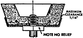
ILLUSTRATION No. 47
Type II cup wheel showing threaded prong-anchor bushing molded into back, and revolving cup guard. Note there is no relief between guard and wheel bushing.
The maximum exposure angles specified in the following paragraphs shall not be exceeded.
Visors or other accessory equipment shall not be include as a part of the guard when measuring the guard opening, unless such equipment has strength equal to that of the guard.
Explanatory Information
(NOT PART OF ANSI CODE)
Maximum guard openings are based on the fact that the line of flight of broken wheel pieces will be tangential in the direction of rotation of the wheel. The maximum exposure angles must not be exceeded.
The angular exposure of the grinding wheel periphery and sides for safety guards used on machines known as bench and floor stands should not exceed 90 degrees or one-fourth of the periphery. This exposure shall begin at a point not more than 65 degrees above the horizontal plane of the wheel spindle. (See Figs. 9 and 10 and section 4.4 page 31.)
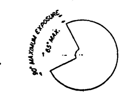
FIGURE NO. 9
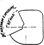
FIGURE NO. 10
Wherever the nature of the work requires contact with the wheel below the horizontal plane of the spindle, the exposure shall not exceed 125 degrees. (See Figs. 11 and 12.)
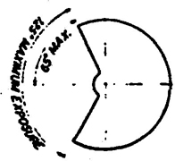
FIGURE NO. 11
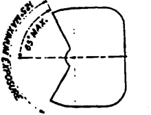
FIGURE NO. 12
Explanatory Information
(NOT PART OF ANSI CODE)
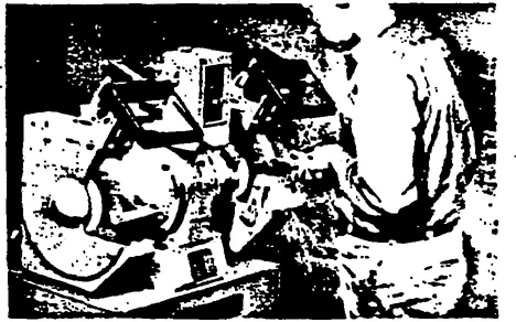
ILLUSTRATION NO. 48
An example of a well-designed guard for a bench grinder. Note that exposure does not exceed the 90° maximum stipulated.
The maximum angular exposure of the grinding wheel periphery and sides for safety guards used on cylindrical grinding machines shall not exceed 180 degrees. This exposure shall begin at A point not more than 65 degrees above the horizontal plane of the wheel spindle. (See Figs. 13 and 14 and section 4.4 page 31.)
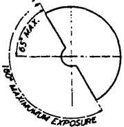
FIGURE NO. 13
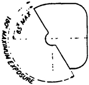
FIGURE NO. 14
Explanatory Information
(NOT PART OF ANSI CODE)
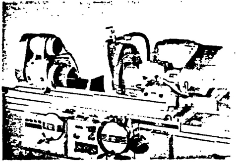
ILLUSTRATION No. 49
A Cylindrical grinding machine employing a well-designed guard.
The maximum angular exposure of the grinding wheel periphery and sides for safety guards used on cutting-off machines and on surface grinding machines which employ the wheel periphery shall not exceed 150 degrees. This exposure shall begin at a point not less than 15 degrees below the horizontal plane of the wheel spindle. (See Figs. 15 and 16.)
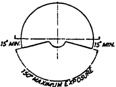
FIGURE NO. 15
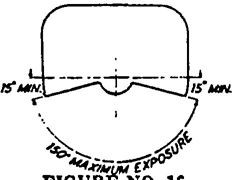
FIGURE NO. 16
Explanatory Information
(NOT PART OF ANSI CODE)
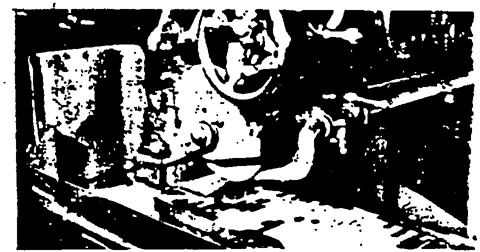
ILLUSTRATION No. 50
This surface grinder has a well-designed guard conforming to basic requirements. The guard is so designed as to allow easy access to the wheel.
The maximum angular exposure of the grinding wheel periphery and sides for safety guards used on machines known as swing frame grinding machines shall not exceed 180 degrees, and the top half of the wheel shall be enclosed at all times. (See Figs. 17 and 18.)
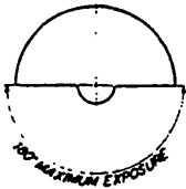
FIGURE NO. 17
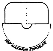
FIGURE NO. 18
Explanatory Information
(NOT PART OF ANSI CODE)
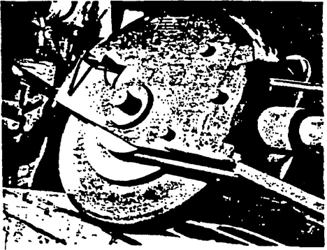
ILLUSTRATION No. 51
This swing frame grinder has an excellent guard. Note that the guard encloses at least 180° of the wheel.
The maximum angular exposure of the grinding wheel periphery and sides for safety guards used on grinders known as automatic snagging machines shall not exceed 180 degrees and the top half of the wheel shall be enclosed at all times. (See Figs. 17 and 18.)
Explanatory Information
(NOT PART OF ANSI CODE)
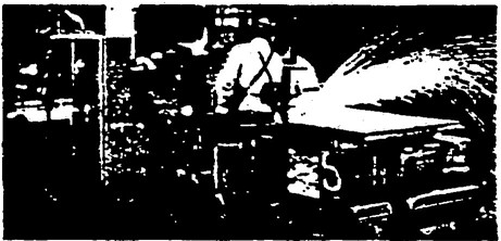
ILLUSTRATION No.52
The operator of a semi-automatic snagging machine easily controls movement of the grinder in all direction
Where the work is applied to the wheel above the horizontal center line, the exposure of the grinding wheel periphery shall be as small as possible and shall not exceed 60 degrees. (See Figs 19 and 20.)
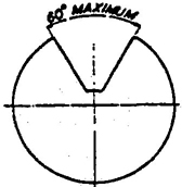
FIGURE NO. 19
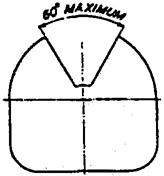
FIGURE NO. 20
Safety guards used on machines known as right angle head or vertical portable grinders shall have a maximum exposure angle of 180 degrees, and the guard shall be so located so us to be between the operator and the wheel during use. Adjustment of guard shall be such that pieces of an accidentally broken wheel will be deflected away from the operator. (See Fig. 39 page 39.)
The maximum angular exposure of the grinding wheel periphery and sides for safety guards used on other portable grinding machines shall not exceed 180 degrees and the top half of the wheel shall be enclosed at all times. (See Figs. 17 and 18.)
Explanatory Information
(NOT PART OF ANSI CODE)
ILLUSTRATION No.53
A Type 27 reinforced wheel properly mounted and guarded on a vertical portable grinder.
Safety guards of the types described in Rules 4.3.1 page 28 and 4.3.2 page 29 where the operator stands in front of the opening, shall be constructed so that the peripheral protecting member can be adjusted to the constantly decreasing diameter of the wheel. The maximum angular exposure above the horizontal plane of the wheel spindle as specified in Rules 4.3.1 page 28 and 4.3.2 page 29 shall never be exceeded, and the distance between the wheel periphery and the adjustable tongue or the end of the peripheral member at the top shall never exceed ¼ inch. (See Figs. 21, 22, 23, 24, 25 and 26.)
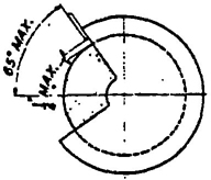
FIGURE NO. 21
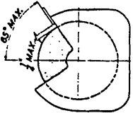
FIGURE NO. 22
CORRECT
Showing adjustable tongue giving required angular protection for all sizes of wheel used.
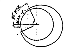
FIGURE NO. 23
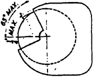
FIGURE NO. 24
CORRECT
Showing movable guard with opening small enough to give required protection for smallest size wheel used.
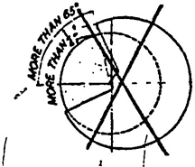
FIGURE NO. 25
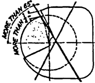
FIGURE NO. 26
INCORRECT
Showing movable guard with size of opening correct for full size wheel but too large for smaller wheels.
Explanatory Information
(NOT PART OF ANSI CODE)
Figures 21, 22, 23 and 24 show two satisfactory methods of accomplishing exposure adjustment. These sketches are for purposes of illustration only. Other methods that agree with the basic rule are also acceptable. Figures 25 and 26 show a condition that does not comply with the requirements.
31The safety guard shall cover, the spindle end, nut, and flange projections. The safety guard shall be mounted so as to maintain proper alignment with the wheel, and the strength of the fastenings shall exceed the strength of the guard.
Exception A — Safety guards on all operations where the work provides a suitable measure of protection to the operator, may be so constructed that the spindle end, nut, and outer flange are exposed; and where the nature of the work is such as to entirely cover the side of the wheel, the side covers of the guard may be omitted.
Exception B — The spindle end, nut and outer flange may be exposed on machines designed as portable saws. (See paragraph 1.4.17, page 14.)
Explanatory Information
(NOT PART OF ANSI CODE)
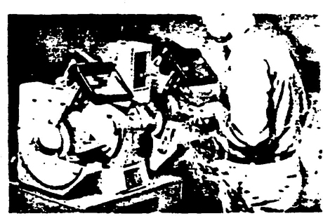
ILLUSTRATION No. 54
An example of a well-designed guard for a bench grinder. Note the side member of the guard is readily removed for access to wheel.
The nature of many operations requires that adjacent personnel other than the operator be afforded protection.
Such protection should take the form of an enclosure which isolates the operation from the remaining working area.
Heavy wire screen, corrugated iron, steel sheet or other suitable material may be used in its construction.
Explanatory Information
(NOT PART OF ANSI CODE)
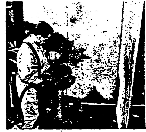
ILLUSTRATION No. 55
Notice the protective screen placed around the grinding area. This auxiliary enclosure isolates the grinding area from the remainder of the plant.
See Figures 33 and 34 and Table 5 page 36 for minimum basic thickness of peripheral and side members for various types of safety guards and classes of service.
Explanatory Information
(NOT PART OF ANSI CODE)
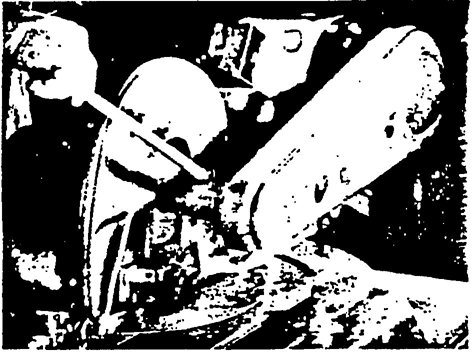
ILLUSTRATION NO. 56
This cutting-off machine is employing a wheel less than is inches in diameter and is operating at a speed less than 16,000 surface feet per minute Note excellent case iron guard.
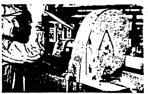
ILLUSTRATION NO. 57
This cutting-off machine has a wheel larger than 16 inches diameter and is operating at a speed less than 14,200 surface feet per minute. Note complete enclosure of wheel by the fabricated safety guard.
ILLUSTRATION NO. 58
Note the heavy cast iron safety guard completely enclosing the cutting-off wheel.
If operating speed does not exceed 8,000 surface feet per minute cast iron safety guards, malleable iron guards or other guards as described in paragraph 4.6.2. shall be used.
Cast steel, or structural steel, safety guards as specified in Table 5 page 36 shall be used where operating speeds of wheels are faster than 8,000 surface feet per minute up to a maximum of 16,000 surface feet per minute.
If materials other than those listed in Table 5 page 36 are used, the thickness of the peripheral and side members shall be such that the resultant safety guard will be as strong or stronger than a similar guard constructed according to Table 5 page 36.
1. For cutting-off wheels* 16 inches diameter and smaller and where speed does not exceed 16,000 surface feet per minute, cast iron or malleable iron safety guards as specified in Table 5 page 36 or other safety guards providing equal or better protection shall be used.
2. For cutting-off wheels* larger than 16 inches diameter and where speed does not exceed 14,200 surface feet per minute, fabricated safety guards as specified in Table 6 page 37 or other safety guards providing equal or better protection shall be used.
3. For thread grinding wheels not exceeding 1 inch in thickness cast iron or malleable iron safety guards as specified in Table 5 page 36 or other safety guards providing equal or better protection shall be used.
*See section 1.4.15 page 14 for cutting-off wheel definition.
33The minimum thickness specifications shown in Tables 5 page 36 and 6 page 37 are based on the following material specifications of the American Society for Testing Materials.
(Excluding specifications for rivet steel.)
Note: Copies of the above listed specifications may be procured at a nominal price from the American Society for Testing Materials, Philadelphia, Pennsylvania.
Other materials having at least equal strength properties and which lend themselves equally well to the desired type of construction may also be used.
Explanatory Information
(NOT PART OF ANSI CODE)
ILLUSTRATION NO. 59
Close-up view of thread grinding wheel. Note the excellent safety guard.
Guides for the construction of fabricated guards of structural steel are shown in Figs. 27 to 32 inclusive and in Table 4 page 35. Two designs are shown. Other designs affording equal or better protection are also acceptable.
The requirements given in Column A of Table 4 page 35 shall apply also to cast guards and in such cases, where the tongue is held by bolts, Column B shall also apply.
Table 7 page 38 may be used as a guide in determining the spacings and size of rivets, bolts and studs to provide satisfactory connections. Any means of fastening shall be considered satisfactory if, when assembled, it has strength at least equal to the tensile strength of the members being joined.
Explanatory Information
(NOT PART OF ANSI CODE)
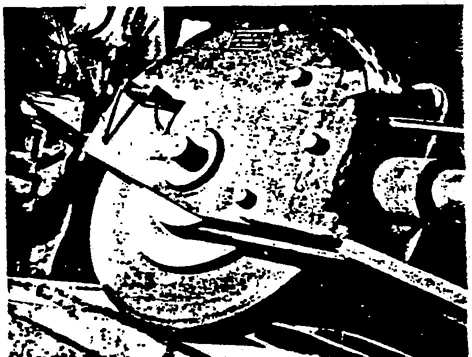
ILLUSTRATION NO. 60
The fabricated safety guards is easily identifiable by the rivets, bolts and welds used in its assembly.
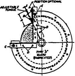
FIGURE NO. 27
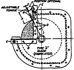
FIGURE NO. 28
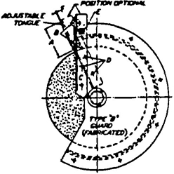
FIGURE NO. 29
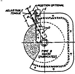
FIGURE NO. 30
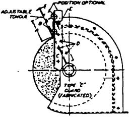
FIGURE NO. 31
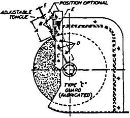
FIGURE NO. 32
See Section 3-4 page 20 for Exhaust Provision.
| A | B | C | D | E | F | G* | H* | |
|---|---|---|---|---|---|---|---|---|
| Diameter of wheel Inches |
Length of Tongue Inches |
Diameter of Bolts Medium-Carbon Queeched & Tempered Inches |
Size of Angle Supports Tongue and Rest Inches |
Diameter of Rivets for Supports Inches |
Diameter of End Connected Bolts Inches |
Thickness of Tongue Inches |
Maximum Space between New Wheel and Guard at Periphery Inches |
Maximum Inside Width of Guard Inches |
| Under 12 | 3½ | [Illegible Text Omitted on Page 35] | 1½ × 1½ × [Illegible Text Omitted on Page 35] | 4 ea @ ½ | ½ | ¼ | 1 ½ | 1½ wider than wheel |
| 16 | 5 | ⅝ | 2 × 2 × [Illegible Text Omitted on Page 35] | 4 ea @ ⅝ | [Illegible Text Omitted on Page 35] | [Illegible Text Omitted on Page 35] | 1 ½ | 2 wider than wheel |
| 24 | 6 | ¾ | 2 × 2 × ½ | 6 ea @ ⅝ | ⅝ | ½ | 1 ½ | 2 wider than wheel |
| 30 | 7 | [Illegible Text Omitted on Page 35] | 2½ × 2½ × ½ | 6 ea @ [Illegible Text Omitted on Page 35] | [Illegible Text Omitted on Page 35] | ½ | 1 ½ | 2 wider than wheel |
| Note: Column D assumes low carbon steel (38000 PSI tensile) rivets. Two rivets per bar 12 and 16′′ diameter. Four rivets per bar 2¼ and 30′′ diameter. | ||||||||
| *Limitations is Columns G and H refer only to guards the shape of which is similar to those shown in figures 27, 29 and 31. | ||||||||
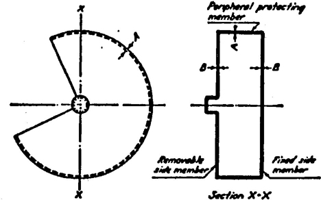
FIGURE NO. 33
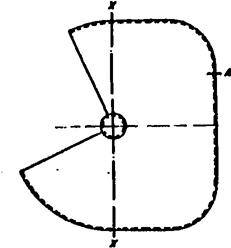
FIGURE NO. 34
| Material Used in Construction of Guard | Maximum Thickness of Grinding Wheel | GRINDING WHEEL DIAMETERS | ||||||||||||||
|---|---|---|---|---|---|---|---|---|---|---|---|---|---|---|---|---|
| 3 to 6 Inches | Over 6 to 12 Inches |
Over 12 to 16 Inches |
Over 16 to 20 Inches |
Over 20 to 24 Inches |
Over 24 to 30 Inches |
Over 30 to 48 Inches |
||||||||||
| A | B | A | B | A | B | A | B | A | B | A | B | A | B | |||
| Material Satisfactory[Illegible Text Omitted on Page 36] for speeds up to 8,000 SFPM | Cast Iron (Min. Tensile Strength 20,000 PSI) Class 20 | Inches | Inches | Inches | Inches | Inches | Inches | Inches | Inches | |||||||
| 2 | ¼ | ¼ | ¼ | 5/16 | ½ | ⅔ | [Illegible Text Omitted on Page 36] | ½ | ⅞ | ⅝ | 1 | [Illegible Text Omitted on Page 36] | 1 [Illegible Text Omitted on Page 36] | 1 | ||
| 4 | 5/16 | 5/16 | ⅜ | 5/16 | ½ | ⅔ | ¾ | ⅝ | 1 | ⅝ | 1 ½ | ¾ | 1 [Illegible Text Omitted on Page 36] | 1 | ||
| 6 | ⅜ | 5/16 | ½ | 7/16 | ⅝ | ½ | 1 | ⅝ | 1 ⅛ | ¾ | 1 ¼ | ⅞ | 1 ¼ | 1 [Illegible Text Omitted on Page 36] | ||
| 8 | ⅝ | 9/16 | ⅞ | ¾ | 1 | ¾ | 1 ⅛ | ¾ | 1 ¼ | ⅞ | 1 ½ | 1 [Illegible Text Omitted on Page 36] | ||||
| 10 | ¾ | 11/16 | ⅞ | ¾ | 1 | ¾ | 1 ⅛ | ¾ | 1¼ | ⅞ | 1 ½ | 1 [Illegible Text Omitted on Page 36] | ||||
| 16 | 1 ½ | 1 | 1 ¼ | 1 | 1 5/16 | 1 | 1 7/16 | 1 1/16 | 1 ¾ | 1 [Illegible Text Omitted on Page 36] | ||||||
| 20 | 1 ⅔ | 1 ⅓ | 1 [Illegible Text Omitted on Page 36] | 1 ⅔ | 1 ½ | 1¾ | 2 | 1 ⅝ | ||||||||
| Material Satisfactory[Illegible Text Omitted on Page 36] for speeds up to 9,000 SFPM | Malleable Iron (Min. Tensile Strength 50,000 PSI) Grade 32510 | 2 | ¼ | ¼ | [Illegible Text Omitted on Page 36] | 5/16 | ½ | [Illegible Text Omitted on Page 36] | ⅝ | ⅓ | ¾ | [Illegible Text Omitted on Page 36] | ⅞ | ¾ | 1 | ⅞ |
| 4 | 5/16 | 5/16 | [Illegible Text Omitted on Page 36] | 5/16 | ½ | [Illegible Text Omitted on Page 36] | ⅝ | [Illegible Text Omitted on Page 36] | ¾ | ⅝ | ⅞ | ¾ | 1 ¼ | ⅞ | ||
| 6 | ⅜ | 5/16 | ½ | 7/16 | ⅝ | ½ | ¾ | ⅝ | ⅞ | ⅝ | 1 | ¾ | 1 ¼ | ⅞ | ||
| 8 | ½ | 7/16 | ⅝ | ½ | ¾ | ⅝ | ⅞ | ⅝ | 1 | ¾ | 1 ¼ | ⅞ | ||||
| 10 | ½ | 7/16 | ⅝ | ½ | ¾ | ⅝ | ⅞ | ⅝ | 1 | ¾ | 1 ¼ | ⅞ | ||||
| 16 | 13/16 | 11/16 | 13/16 | 11/16 | 1 | ¾ | 1 ½ | ⅞ | 1 [Illegible Text Omitted on Page 36] | 1 | ||||||
| 20 | ⅞ | ¾ | 1 | ¾ | 1 ½ | ⅞ | 1 ½ | 1 ¼ | ||||||||
| Materials Satisfactory for speeds up to 16,000 SFPM | Steel Castings Min. Tensile Strength 60,000 PSI) Grade V60-80 | 2 | ¼ | ¼ | 5/16 | 5/16 | ⅔ | ⅔ | ½ | 7/16 | ⅝ | ½ | ¾ | ⅝ | ⅞ | ¾ |
| 4 | ¼ | ¼ | ½ | ½ | ½ | ½ | 9/16 | ½ | ⅝ | ½ | ¾ | ⅝ | 1 | ¾ | ||
| 6 | ⅔ | ¼ | ¾ | ⅝ | ¾ | ⅝ | ¾ | ⅝ | 13/16 | 11/16 | 13/16 | 11/16 | 1 [Illegible Text Omitted on Page 36] | ¾ | ||
| 8 | ⅞ | ¾ | ⅞ | ¾ | ⅞ | [Illegible Text Omitted on Page 36] | ⅞ | ¾ | 15/16 | 13/16 | 1 ⅔ | 1 | ||||
| 10 | 1 | ⅞ | 1 | ⅞ | 1 | ⅞ | 1⅓ | 15/16 | 1 ½ | 1 | 1 7/16 | 1 1/16 | ||||
| 16 | 1 ¼ | 1 ½ | 1 ¼ | 1 ½ | 1 ¼ | 1 [Illegible Text Omitted on Page 36] | 1 ¼ | 1 ⅛ | 1 13/16 | 1 7/16 | ||||||
| 20 | 1 ¾ | 1 ¼ | 1 ¾ | 1¼ | 1 7/16 | 1 5/16 | 2 1/16 | 1 11/16 | ||||||||
| Structural Steel (Min. Tensile Strength 60,000 PSI) | 2 | ¼ | 1/16 | 5/16 | ¼ | 5/16 | ¼ | 5/16 | ¼ | 5/16 | ¼ | ⅔ | 5/16 | ½ | ⅔ | |
| 4 | [Illegible Text Omitted on Page 36] | 1/16 | [Illegible Text Omitted on Page 36] | 5/16 | ⅔ | 5/16 | ⅔ | 5/16 | ⅔ | 5/16 | ⅔ | 5/16 | ½ | ⅔ | ||
| 6 | 3/16 | 1/16 | ½ | ⅔ | 7/16 | [Illegible Text Omitted on Page 36] | 7/16 | [Illegible Text Omitted on Page 36] | 7/16 | [Illegible Text Omitted on Page 36] | 7/16 | [Illegible Text Omitted on Page 36] | ¾ | ½ | ||
| 8 | ½ | [Illegible Text Omitted on Page 36] | 9/16 | 7/16 | 9/16 | 7/16 | 9/16 | 7/16 | ⅝ | ½ | ¾ | ½ | ||||
| 10 | 9/16 | 7/16 | [Illegible Text Omitted on Page 36] | ½ | ⅝ | ½ | ⅝ | ½ | ⅝ | ½ | ⅞ | [Illegible Text Omitted on Page 36] | ||||
| 16 | 9/16 | ¾ | ⅝ | ¾ | ⅝ | 13/16 | 11/16 | 1 1/16 | [Illegible Text Omitted on Page 36] | |||||||
| 20 | 13/16 | 11/16 | 13/16 | 11/16 | ⅞ | [Illegible Text Omitted on Page 36] | 1 3/16 | [Illegible Text Omitted on Page 36] | ||||||||
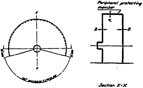
FIGURE NO. 35
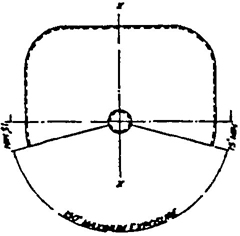
FIGURE NO. 36
| Material Used in Construction of Guard | Maximum Thickness of Cutting Off Wheel | Speed Not to Exceed | Cutting Off Wheel Diameters | |||||||||
|---|---|---|---|---|---|---|---|---|---|---|---|---|
| 6 to 11 inches | Over 11 to 20 in. | Over 20 to 30 in. | Over 30 to 48 in. | Over 48 to 72 in. | ||||||||
| A | B | A | B | A | B | A | B | A | B | |||
| Structural Steel (Min. Tensile Strength 60,000 PSI) | ½ inch or less | 14,200 SFPM | inches | |||||||||
| 1/16 | 1/16 | 1/32 | 1/32 | [Illegible Text Omitted on Page 37] | [Illegible Text Omitted on Page 37] | 3/16 | 3/16 | ¼ | ¼ | |||
| ½ inch or less | 16,000 SFPM | inches | ||||||||||
| 3/32 | [Illegible Text Omitted on Page 37] | [Illegible Text Omitted on Page 37] | [Illegible Text Omitted on Page 37] | 3/16 | [Illegible Text Omitted on Page 37] | ¼ | 3/16 | 5/16 | ¼ | |||
As a guide for the construction of drawn steel guards for wheel 8 inches diameter and smaller, Figure 38 and Table 8 page 39 have been prepared. Other designs affording equal or better protection are also acceptable.
Special design drawn steel guards for use with Types 27 and 28 abrasive wheels on portable machines are shown in Fig. 39 page 39. An essential feature of design is the lip on the outer edge which curls inward to deflect places if a wheel is broken in the 180° are next to the operator and to provide necessary strength with light sheet steel.
Dimension B shall be sufficient to allow the lip to curl outside the wheel.
Explanatory Information
(NOT PART OF ANSI CODE)
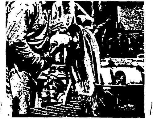
ILLUSTRATION NO. 61
A typical application of the drawn steel safety guard.
GUIDE SHOWING CORRECT FASTENING PROCEDURE
FOR SIDE MEMBERS (See Section 4.8 page 34)
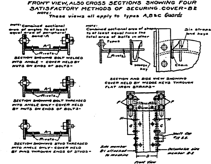
FIGURE NO. 37
| Thickness of Plates being Connected | FOR SIDE PLATE (B-1) ATTACHED TO MACHINE | FOR DETACHABLE SIDE PLATE (B-2) | ||
|---|---|---|---|---|
| Diameter of Rivets | Maximum Distance between Centers | Diameter of Bolts or Studs | Maximum Distance between Centers | |
| Inches 1/8 and 1/16 3/16 " 1/16 3/16 “ ⅛ |
Inches 5/16 5/16 5/16 |
Inches 3 3 3 |
Inches 7/16 7/16 7/16 |
Inches 6 6 6 |
| 3/16 " 1/16 ¼ “ ⅛ ¼ “ 3/16 |
5/16 [Illegible Text Omitted on Page 38] ⅔ |
3 4 3½ |
7/16 9/16 9/16 |
6 8 7 |
| ¼ " ¼ 5/16 “ 3/16 5/16 “ ¼ |
[Illegible Text Omitted on Page 38] 9/16 9/16 |
3 4 4 |
9/16 13/16 13/16 |
6 8 8 |
| ⅔ " ¼ 5/16 “ 3/16 5/16 “ ¼ |
9/16 9/16 9/16 |
4 3½ 3 |
13/16 13/16 13/16 |
8 7 6 |
| 7/16 “ 5/16 ¼ “ 5/16 ¼ “ [Illegible Text Omitted on Page 38] |
[Illegible Text Omitted on Page 38] [Illegible Text Omitted on Page 38] [Illegible Text Omitted on Page 38] |
3 3 3 |
13/16 13/16 13/16 |
6 6 6 |
| ⅝ “ [Illegible Text Omitted on Page 38] 11/16 “ 7/16 |
⅝ ⅝ |
3 3 |
[Illegible Text Omitted on Page 38] [Illegible Text Omitted on Page 38] |
6 6 |
TYPICAL DRAWN STEEL GUARD FOR WHEELS
8 Inches Diameter and Smaller (See Section 4.10 page 37)
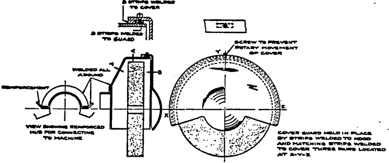
FIGURE NO. 38
| Material Used in Construction of Guard Hot Rolled Steel SAE 1008 Min. Tensile Strength 60,000 PSI | Maximum Thickness of Wheel, Inches | ||||
|---|---|---|---|---|---|
| 2 to 5 Inches | Above 5 to 8 Inches | ||||
| A | B | A | B | ||
| For Speeds Up to (SFPM) | |||||
| Inches | Inches | ||||
| 9,500 | 2 | 1/16 | 1/16 | [Illegible Text Omitted on Page 39] | 1/16 |
| 12,500 | 2 | [Illegible Text Omitted on Page 39] | 1/16 | [Illegible Text Omitted on Page 39] | [Illegible Text Omitted on Page 39] |
| 17,000 | 1 | [Illegible Text Omitted on Page 39] | 1/16 | [Illegible Text Omitted on Page 39] | [Illegible Text Omitted on Page 39] |
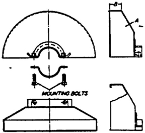
FIGURE NO. 39
| Material Used in Construction of Guard | Thickness of Wheel | Wheel Diameter Inches | A Inches | B Inches | |
|---|---|---|---|---|---|
| For speeds up to 14,200 SFPM | Hot Rolled Steel SAE 1008 min. tensile strength 60,000 PSI | [Illegible Text Omitted on Page 39] inches or less | 2 to 9 | 1/16 | ½ |
| Over [Illegible Text Omitted on Page 39] to 1 Inch | 7 to 9 | [Illegible Text Omitted on Page 39] | 1 [Illegible Text Omitted on Page 39] | ||
Band type guards shall conform to the following general specifications:
(a) The bands shall be of steel plate or other material of equal or greater strength. They shall be continuous, the ends being either riveted, bolted or welded together in such a manner as to leave the inside free from projections.
(b) The inside diameter of the band shall not be more than 1 inch larger than the outside diameter of the wheel, and shall be mounted as nearly concentric with the wheel as practical.
(c) The band shall be of sufficient width and its position kept so adjusted that at no time will the wheel protrude beyond the edge of the band a distance greater than indicated in Table 10 page 41; nor the wall thickness (W) whichever of these dimensions is smaller.
Explanatory Information
(NOT PART OF ANSI CODE)
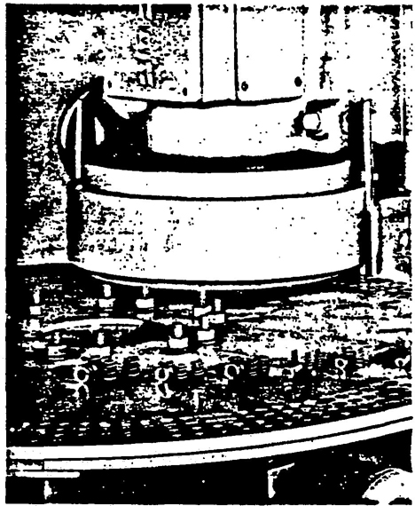
ILLUSTRATION NO. 62
A property constructed band type guard. Notice that the exposure of the abrasive wheel is in conformance with the requirements listed in Table 11.
As a guide for the construction of band type guards, Figure 40 and Table 11 page 41 have been prepared. Other designs affording equal or better protection are also acceptable.
Explanatory Information
(NOT PART OF ANSI CODE)
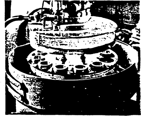
ILLUSTRATION NO. 63
Another example of a well constructed band type guard.
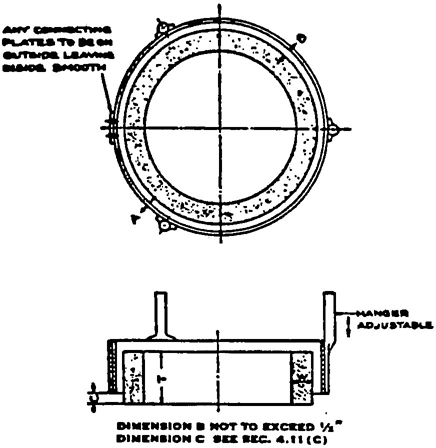
FIGURE NO. 40
| Overall Thickness of Wheel (T) Inches | Maximum Exposure of Wheel (C) Inches |
| ½ . . . . . . . . . . . . . . . | ¼ |
| 1 . . . . . . . . . . . . . . . | ½ |
| 2 . . . . . . . . . . . . . . . | ¾ |
| 3 . . . . . . . . . . . . . . . | 1 |
| 4 . . . . . . . . . . . . . . . | 1½ |
| 5 and over . . . . . | 2 |
| Minimum Material Specifications | Diameter of Wheel | Minimum Thickness of Band A | Minimum Diameter of Rivets | Maximum Distance between Centers of Rivets |
|---|---|---|---|---|
| Hot Rolled Steel SAE 1008 | Inches Under 8 |
Inches 1/16 |
Inches 3/16 |
Inches ¾ |
| 8 to 24 | ⅛ | ¼ | 1 | |
| Over 24 to 30 | [Illegible Text Omitted on Page 41] | [Illegible Text Omitted on Page 41] | 1 [Illegible Text Omitted on Page 41] |
All abrasive wheels shall be mounted between flanges which shall not be less than one-third the diameter of the wheel.
Exceptions:
Explanatory Information
(NOT PART OF ANSI CODE)
The major stresses produced in an operating grinding wheel tend to combine and become greatest at the hole. It is, therefore, important that stresses due to mounting and driving, act as far from the hole as practicable.
This is best accomplished by using flanges at least as large as those listed in Tables 12, 13, 14, 15, 16, 17, 18 and 19, pages 47, 48, 49, 50 and 51.
Flanges should be at least minimum diameters specified, identical in diameter and radial bearing surface to avoid cross bending pressures and stresses in the wheel structure. Cutting-off wheel flange diameter equal to ¼ the wheel diameter is a minimum requirement. In many cutting-off operations, better results may be obtained through the use of larger flanges.
Blotters (Compressible Washers) should always be used between metal flanges and abrasive wheel surfaces for uniform distribution of flange pressure.
See Sec. 5.6 page 44 for exceptions regarding the use of blotters.
Flanges shall be checked periodically for flatness, burrs or wear.
Type 1 cutting-off wheels are to be mounted between properly relieved flanges which have matching bearing surfaces. Such flanges shall be at least one-fourth the wheel diameter.
Type 27A cutting-off wheels are designed to be mounted by means of flat, not relieved, flanges having matching bearing surfaces and which may be less than one-third but shall not be less than one-fourth the wheel diameter. See Illustration 77 page 56 for one such type of mounting.
42There are three general types of flanges: straight relieved flanges (see Figure 41 page 47); straight unrelieved flanges (see Figure 42 page 48); adaptor flanges (see Figures 44 and 45, page 49).
Regardless of flange type used, the wheel shall always be guarded. (See section 4 page 27.) Blotters shall be used as listed in section 5.6 page 44.
Flanges shall be of such design as to satisfactorily transmit the driving torque from the spindle to the grinding wheel.
Flanges may be made of steel, cast iron or other material of equal or greater strength and rigidity.
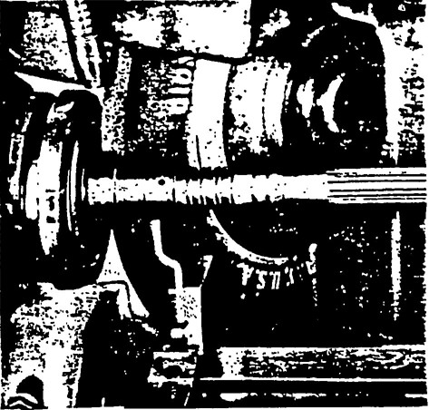
ILLUSTRATION No. 64
Note the flanges used here are at least ⅓ diameter of wheel; finished all over, and free of rough or sharp edges.
Flanges shall be dimensionally accurate and in good balance. There shall be no rough surfaces or sharp edges.
Both flanges, of any type, between which a wheel is mounted, shall be of the same diameter and have equal bearing surface.
Exception: Types 27 and 28 wheels are designed to be mounted by means of a special adaptor (see Illus. No. 65 for one type of adaptor). Modified types 6 and 11 wheels (terrazzo) with tapered K dimension (see section 1.4.20 page 15). Equivalent or better mounting techniques may also be used. (See section 6.15 page 56.)
Explanatory Information
(NOT PART OF ANSI CODE)
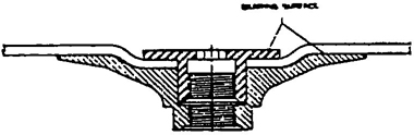
ILLUSTRATION No. 65
One type of adaptor for a Type 27 wheel.
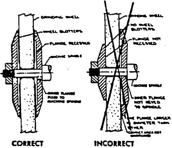
ILLUSTRATION No. 66
Proper and improper methods of mounting wheels having small holes.
Straight relieved flanges made according to Fig. 41 page 47 shall be recessed at least 1/16 ″ on the side next to the wheel for a distance as specified in the respective tables of dimensions for these flanges.
Straight flanges of the adaptor or sleeve type (Figs. 44 and 45 page 49) shall be undercut so that there will be no bearing on the sides of the wheel within 1/8 inch of the arbor hole.
Exception:
Explanatory Information
(NOT PART OF ANSI CODE)
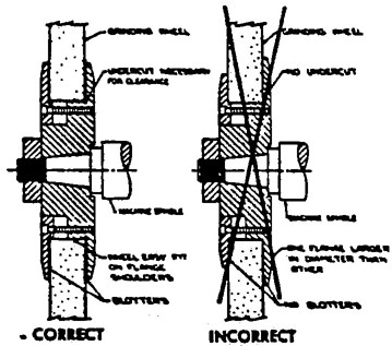
ILLUSTRATION No. 67
Proper and improper methods of mounting wheels having large holes.
The driving flange shall be securely fastened to the spindle and the bearing surface shall run true.
Explanatory Information
(NOT PART OF ANSI CODE)
The driving flange shall be checked on a regularly maintained schedule for any damage or run-out.
When more than one wheel is mounted between a single set of flanges, wheels may be cemented together or separated by specially designed spacers. Spacers shall be equal in diameter to the mounting flanges and have equal bearing surfaces. (See section 6.7, page 53.)
Explanatory Information
(NOT PART OF ANSI CODE)
In certain multiple wheel operations where wheel slippage may be a problem it may be necessary to key or otherwise securely fasten both the spacers and the outside flange to the spindle.
Explanatory Information
(NOT PART OF ANSI CODE)
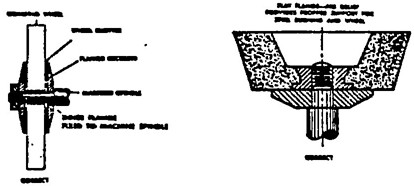
ILLUSTRATION No. 68
The proper flange assemblies for Type 1 and Type 11 wheels.
The tables show minimum dimensions for straight relieved and unrelieved flanges for use with wheels with small holes that fit directly on the machine spindle. Dimensions of such flanges shall never be less than indicated and should be greater where practicable.
Table 14 page 48 and table 15 page 49 shows minimum dimensions for straight adaptor flanges for use with wheels having holes larger than the spindle. Dimensions of such adaptor flanges shall never be less than indicated and should be greater where practicable.
Note: Inorganic wheels with large holes are not recommended for snagging. (See section 9.13 page 68.)
Explanatory Information
(NOT PART OF ANSI CODE)
Flanges of this type are frequently used with organic bonded snagging wheels having large holes.
Inorganic wheels with large holes are not recommended for-rough snagging operations. These wheels are not suitable for current methods of reinforcement and therefore, it is necessary for the wheels to have small holes and be used with straight relieved or tapered safety flanges.
45Table 19 page 51 shows minimum dimensions for straight flanges that are an integral part of wheel sleeves which are frequently used on precision grinding machines. Dimensions of such flanges shall never be less than indicated and should be greater where practicable.
Explanatory Information
(NOT PART OF ANSI CODE)
In mounting large hole wheels, it is most important that equipment and mounting procedures are satisfactory to avoid distorting of flanges. Careful mounting procedures, using new clean-blotters and gradual criss-cross tightening of the mounting screws, are important. Excessive tightening beyond that necessary to drive the wheel without slippage results in abnormal stresses near the hole. This must be avoided.
All flanges shall be maintained in good condition. When the bearing surfaces become worn, warped, sprung or damaged they should be trued or refaced. When refacing or truing, care shall be exercised to make sure that proper relief and rigidity is maintained as specified in Sections 5.5 and 5.6 page 44 and they shall be replaced when they do not conform to these Sections and Tables 12, 13, 14, or 19 pages 47, 48 and 51. Failure to observe these rules might cause excessive flange pressure around the hole of the wheel. This is especially true of wheel-sleeve or adaptor flanges.
All flanges should be frequently inspected for compliance with this rule.
Explanatory Information
(NOT PART OF ANSI CODE)
A Standard Inspection Frequency Schedule should be adopted by each grinding wheel user depending on his experience and severity of use.
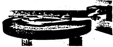
ILLUSTRATION No. 69
Check flanges with straight edge to be sure they are not warped or sprung.
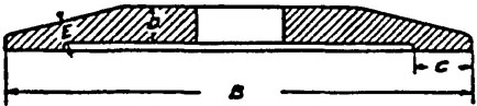
FIGURE NO 41
Driving flange secured to spindle. See Section 5.7 Page 45.
| A* Diameter of Wheel |
B(1) Minimum Outside Diameter of Flanges |
C Radial Width of Bearing Surface |
D Minimum Thickness of Flange at Bore |
E Minimum Thickness of Flange at Edge of Recess |
|
|---|---|---|---|---|---|
| Minimum | Maximum | ||||
| Inches 1 2 3 |
Inches [Illegible Text Omitted on Page 47] 11/16 1 |
Inches 1/16 ½ ½ |
Inches ½ [Illegible Text Omitted on Page 47] 3/16 |
Inches 1/16 ½ [Illegible Text Omitted on Page 47] |
Inches 1/16 [Illegible Text Omitted on Page 47] [Illegible Text Omitted on Page 47] |
| 4 5 6 7 |
1 [Illegible Text Omitted on Page 47] 111/16 2 2 [Illegible Text Omitted on Page 47] |
½ 3/16 ¼ ¼ |
3/16 ¼ ½ ½ |
[Illegible Text Omitted on Page 47] ¼ [Illegible Text Omitted on Page 47] [Illegible Text Omitted on Page 47] |
½ ½ 3/16 3/16 |
| 8 10 12 |
2 11/16 3 ⅔ 4 |
¼ 3/16 5/16 |
¼ ⅝ ⅝ |
⅔ ⅔ ½ |
3/16 ¼ 5/16 |
| 14 16 18 |
4 11/16 5 ⅔ 6 |
⅔ ½ ½ |
¾ 1 1 |
½ ½ ⅝ |
[Illegible Text Omitted on Page 47] 5/16 [Illegible Text Omitted on Page 47] |
| 20 22 24 |
6 11/16 7⅜ 8 |
[Illegible Text Omitted on Page 47] [Illegible Text Omitted on Page 47] ¾ |
1 ¼ 1 ¼ 1 ¼ |
⅝ ⅝ ⅝ |
⅜ [Illegible Text Omitted on Page 47] [Illegible Text Omitted on Page 47] |
| 26 28 30 |
8 11/16 9 [Illegible Text Omitted on Page 47] 10 |
¾ ⅞ ⅞ |
1 ¼ 1 ½ 1 ½ |
⅝ ¾ ¾ |
½ ½ ⅝ |
| 36 | 12 | 1 | 2 | ⅞ | ¾ |
| 42 48 60 72 |
14 16 20 24 |
1 1 ¼ 1 ¼ 1 ½ |
2 2 2 2 ½ |
⅞ 1 ½ 1 ¼ 1 [Illegible Text Omitted on Page 47] |
¾ 1 1 [Illegible Text Omitted on Page 47] 1¼ |
| *Flanges for wheels under 2 inches diameter may be unrelieved and shall be maintained flat and true. (1) For exceptions to minimum outside diameter of flanges, see paragraph 5.1 and 5.1.1. Dimensions listed are rounded to + 1/16 inches. |
|||||
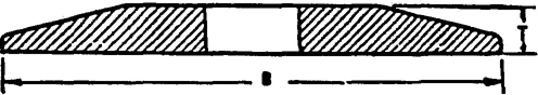
FIGURE NO. 42
Driving flange secured to spindle for use only on portable wheels with threaded inserts or projecting studs.
| A Diameter of Wheel |
B* Minimum Outside Diameter of Flange |
T Minimum Thickness of Flange |
|---|---|---|
| Inches | Inches | Inches |
| 1 | ⅝ | [Illegible Text Omitted on Page 48] |
| 2 | 1 | ½ |
| 3 | 1 | 3/16 |
| 4 | 1 ⅜ | 3/16 |
| 5 | 1 ¾ | [Illegible Text Omitted on Page 48] |
| 6 | 2 | [Illegible Text Omitted on Page 48] |
| *NOTE: Must be large enough to extend beyond the bushing. Where prong anchor or cupback bushing are used, this footnote does not apply. | ||
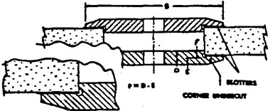
FIGURE NO. 43
| Wheel Diameter | Wheel Hole Diameter | B Minimum Flange Diameter |
D Minimum Thickness of Flange at Bore |
E Minimum Thickness of Flange at Edge of Undercut |
F* (D-E) Minimum Thickness |
|---|---|---|---|---|---|
| Inches 12 to 14 |
Inches 4 5 6 |
Inches 6 7 8 |
Inches ⅞ ⅞ ⅞ |
Inches ⅜ ⅜ ⅜ |
Inches ½ ½ ½ |
| Larger than 14 to 18 |
4 5 6 7 8 |
6 7 8 9 10 |
⅞ ⅞ ⅞ ⅞ ⅞ |
⅜ ⅜ ⅜ ⅜ ⅜ |
½ ½ ½ ½ ½ |
| Larger than 18 to 24 |
6 7 8 10 12 |
8 9 10 12 14 |
1 1 1 1 1 |
½ ½ ½ ½ ½ |
½ ½ ½ ½ ½ |
| Larger than 24 to 30 | 12 | 15 | 1 | ½ | ½ |
| Larger than 30 to 36 | 12 | 15 | 1½ | ⅞ | ½ |
| *For wheels under 1 ¼ inch thick F dimension shall not exceed 40% of wheel thickness. | |||||
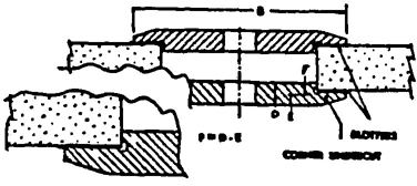
FIGURE NO. 44
Central Nut Mounting
Driving flange secured to spindle. See Section 5.7 Page 45.
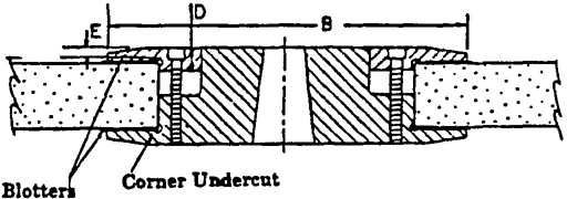
FIGURE NO. 45
Multiple Screw Mounting
Driving flange secured to spindle. See Section 5.7 Page 45.
| Wheel Diameter | Wheel Hole Diameter | “B” Minimum Flange Diameter | “D” Minimum Thickness of Flange at Bore | “E” Minimum Thickness of Flange at Edge of Undercut | F*(D-E) Minimum Thickness |
|---|---|---|---|---|---|
| 20 20 24 30 36 |
6 8 12 12 12 |
8 10 15 15 15 |
1 1 ½ 2 2 2 |
½ ¾ 1 1 1 |
½ ¾ 1 1 1 |
| (1) FLANGES shall be of steel, quality SAE 1040 or equivalent, annealed plate, heat treated to Rc 25-30. *For wheels under 1 ¼ inch thick F dimension shall not exceed 40% of wheel thickness. |
|||||
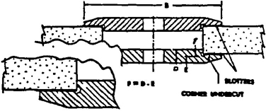
FIGURE NO. 46
Driving flange secured to spindle. See Section 5.7 Page 45.
| Wheel Diameter | Wheel Hole Diameter | “B” Minimum Flange Diameter | “D” Minimum Thickness of Flange at Bore | “E” Minimum Thickness of Flange at Edge of Undercut | F*(D-E) Minimum Thickness |
|---|---|---|---|---|---|
| 20 20 24 30 |
6 8 12 12 |
8 10 15 15 |
1 1 1 ¼ 1 ¼ |
½ ½ ¾ ¾ |
½ ½ ½ ½ |
| (1) FLANGES shall be of steel, quality SAE 1040 or equivalent, annealed plate, heat treated to Rc 25-30. *For wheels under 1 ¼ inch thick F dimension shall not exceed 40% of wheel thickness. |
|||||
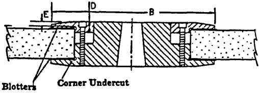
FIGURE NO. 47
Multiple Screw Mounting
Driving flange secured to spindle. See Section 5.7 Page 45.
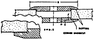
FIGURE NO. 48
Central Nut Mounting
Driving flange secured to spindle. See Section 5.7 Page 45.
| Wheel Diameter | Hole Diameter | “B” Minimum Flange Diameter | “D” Minimum (2) Thickness of Flange at Bore |
|---|---|---|---|
| 20 24 30 |
6 thru 10 12 12 |
8 thru 12 15 15 |
1 1 ¼ 1 ¼ |
| (1) FLANGES shall be of steel, quality SAE 1040 or equivalent, annealed plate, heat treated to Rc 25-30. (2) For central nut mounting, increase “D” dimension by ½ in. for each wheel size shown. For flanges not heat treated, increase “D” dimension by ½ in. for each wheel size shown. |
|||
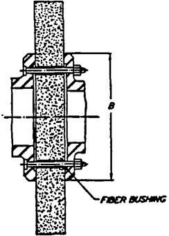
FIGURE NO. 49
Double End Spindle
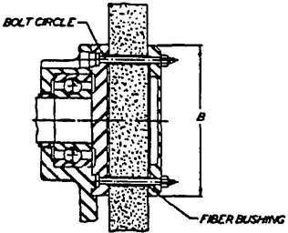
FIGURE NO. 50
Open End Spindle
| Wheel Diameter | Bolt Circle Diameter | “B” Minimum Flange Diameter | Torque Used in Mounting Ft. Lbs. | Mounting Hole Size Dimensions. (8 holes) (holes equally spaced) |
|---|---|---|---|---|
| 16 20 24 30 |
6 ½ 8 9 [Illegible Text Omitted on Page 50] 12 |
8 [Illegible Text Omitted on Page 50] 10 [Illegible Text Omitted on Page 50] 12 14 ¾ |
30—40 30—40 40—50 40—50 |
All mounting holes shall be [Illegible Text Omitted on Page 50] Inside diameter, with a fiber bushing in place, not to exceed [Illegible Text Omitted on Page 50] outside diameter. |
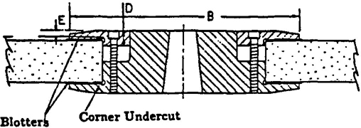
FIGURE NO. 51
Driving flange secured to spindle. See Section 5.7 Page 45.
| Wheel Diameter | Wheel Hole Diameter |
B Minimum Outside Diameter of Flange |
D Minimum Thickness of Flange at Bore |
E Minimum Thickness of Flange at Edge of Undercut |
|---|---|---|---|---|
| Inches 12 to 14 |
Inches 5 |
Inches 7 |
Inches ½ |
Inches [Illegible Text Omitted on Page 51] |
| Larger than 14 to 20 | 5 6 8 10 12 |
7 8 10 11 ½ 13 ½ |
⅝ ⅝ ⅝ ⅝ ⅝ |
[Illegible Text Omitted on Page 51] [Illegible Text Omitted on Page 51] [Illegible Text Omitted on Page 51] [Illegible Text Omitted on Page 51] [Illegible Text Omitted on Page 51] |
| Larger than 20 to 30 | 8 10 12 16 |
10 11 ½ 13 ½ 17 ½ |
¾ ¾ ¾ ¾ |
½ ½ ½ ½ |
| Larger than 30 to 42 | 12 16 18 20 |
13 ½ 17 ½ 19 ½ 21 ½ |
¾ ¾ ¾ ¾ |
½ ½ ½ ½ |
| Larger than 42 to 60 | 16 20 24 |
20 24 29 |
1 1 1 ½ |
¾ ¾ ⅞ |
| Note: These flanges may be clamped together by means of a central nut, or by a series of bolts or some other equivalent means of fastening. For hole sizes smaller than shown in this table, use table 12. | ||||
Immediately before mounting, all wheels shall be closely inspected and sounded by the user (ring test, see section 2.3 page 18) to make sure they have not been damaged in transit, storage or otherwise. The spindle speed of the machine shall be checked before mounting of the wheel to be certain that it does not exceed the maximum operating speed marked on the wheel.
Explanatory Information
(NOT PART OF ANSI CODE)
A cracked wheel is unsafe and must not be used. If any evidence of damage is found, the information should be reported to the manufacturer and arrangements made for inspection.

ILLUSTRATION No. 70
“Ring test”
Grinding wheels shall fit freely on the spindle and remain free under all grinding conditions. A controlled clearance between the wheel hole and the machine spindle (or wheel sleeves or adaptors) is essential to avoid excessive pressure from mounting and spindle expansion.
To accomplish this, the machine spindle shall be made to nominal (standard) size plus zero minus .002 inches, and the wheel hole shall be made suitably over size to assure safety clearance under the conditions of operating heat and pressure. The spindle diameter should not be less than listed in section 3.5 page 21 and Table 1 page 22.
Explanatory Information
(NOT PART OF ANSI CODE)
The machine spindle or adaptor size must be maintained by the user. Worn or undersize spindles or adaptors can cause an out-of-balance condition, contributing to wheel failure.
All contact surfaces of wheels, blotters and flanges shall be flat and free of foreign matter.
Explanatory Information
(NOT PART OF ANSI CODE)
Flanges can be distorted by excessive tightening or burred by dropping and should be checked periodically. (See section 5.9 page 46 Repairs and Maintenance.) Inspection for foreign particles should be made on wheels, blotters and flanges.
Presence of foreign particles in these areas can result in uneven pressure against the sides of the wheel causing stresses that can lead to wheel failure. Scuffed or damaged blotters should be replaced.
When a bushing is used in the wheel hole it shall not exceed the width of the wheel and shall not contact the flanges. Loose reducing bushing (not mechanically held) should not be used with wheels less than ½ inch in thickness.
Explanatory Information
(NOT PART OF ANSI CODE)
If a bushing is wider than the wheel in which it is used it will interefere with proper tightening of the flanges against the wheel.
The power required to drive a grinding wheel is transferred through the flanges. If this power is partially or completely transferred through the bushing, wheel failure may result.
52When blotters or flange facings of compressible material are required, they shall cover entire contact area of wheel flanges.
Highly compressible material such as blotting paper as normally used should not exceed .025 inches in thickness.
If material of lower compressibility is used, greater thickness may be necessary.
Blotters need not be used with the following types of wheels:
Explanatory Information
(NOT PART OF ANSI CODE)
Blotters are used for several reasons. The tend to cushion the pressure of the flanges against high points or uneven surfaces and distribute the pressure evenly. They prevent damage to the surfaces of the flanges from the abrasive surface of the wheel. They provide a better coefficient of friction than would be obtained between the flange and the wheel, there by providing better transmission of the driving power to the wheel.
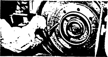
ILLUSTRATION No. 71
Note the blotter between the abrasive wheel and the flange.
All abrasive wheels shall be mounted between flanges which should not be less than one-third the diameter of the wheel. For exceptions and further explanation see section 5 page 42.
Explanatory Information
(NOT PART OF ANSI CODE)
Flanges drive the wheel and must have sufficient contact area. They must be of proper design to prevent distortion causing damaging stresses in the wheel.
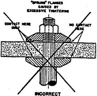
ILLUSTRATION No. 72
The above clearly illustrates the results encountered when the spindle end nut is excessively tightened.
When more than one wheel is mounted between a single set of flanges, wheels may be cemented together or separated by specially designed spacers. Spacers shall be equal in diameter to the mounting flanges and have equal bearing surfaces. When mounting wheels which have not been cemented together, or ones which have do not been cemented together, or ones which do not utilize separating spacers, care must be exercised to use wheels specially manufactured for that purpose. (See section 5.7.1, page 45.)
Explanatory Information
(NOT PART OF ANSI CODE)
Soft compressible blotter material is not generally satisfactory for use as a spacer. Spacers should be of material rated as of low compressibility such as soft copper or brass.
53The spindle end nut shall only be tightened sufficiently to drive the wheel and prevent slippage.
Multiple screw flanges shall be tightened uniformly to prevent springing of the flanges and to insure even distribution of mounting pressure over entire surface of the flanges.
Explanatory Information
(NOT PART OF ANSI CODE)
The gradual tightening of screws on multiple screw type flanges by use of a torque wrench is recommended. The tightening should proceed from one screw to one diametrically opposite and then in a criss cross manner until sufficient pressure is applied uniformly to prevent slippage. Care must be taken to avoid excessive tightening as it may cause springing of the flanges resulting in wheel breakage. Torque pressure of 15 to 20 foot pounds is common with single wheel mounting, however, some exceptionally severe operations require greater pressure.
If flanges are tightened by means of a central nut, three conditions shall be maintained.
Explanatory Information
(NOT PART OF ANSI CODE)
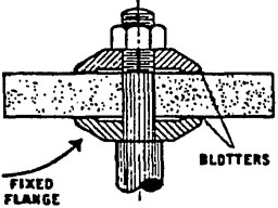
ILLUSTRATION No. 73
The spindle is of sufficient length to accommodate the wheel and flanges.
Special consideration other than listed above must be given to threaded hole wheels of the following types: 5, 6, 11, 16, 17, 18, 18R and 19.
The machine spindle for such wheels shall be provided with an unrelieved flat fixed back flange to allow the wheel to be screwed firmly against it.
The direction of the thread shall be such that to remove the wheel it must be turned in the same direction it rotates when in use.
The length of the spindle shall be such that it shall not bottom in blind threaded hole type wheels.
Explanatory Information
(NOT PART OF ANSI CODE)
When threaded hole wheels are used, as in cups, cones and plugs, the size and mass of threaded hole wheels shall be kept within limits which have been found safe by experience for this mounting procedure.
With this type of mounting, a relieved back flange shall not be used. If made with a relief, if can pull the bushing out of the wheel. See Illustration No. 74.
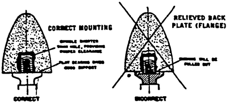
ILLUSTRATION No. 74
Mounting of threaded hole wheels.
6.10 Threaded Hole Wheels
Threaded hole wheel mounting should not be used with wheels larger than 6 inches diameter.
Threads in threaded hole wheels should be of class 2B fit and should be relieved on the side fitting against the flange so as to allow the wheel to be screwed firmly and flat against the back flange.
For requirements for mounting of abrasive discs see section 3.13 page 25.
For requirements for mounting plate mounted type wheels see section 3.14 page 26.
At the completion of wheel mounting the safety guard should be checked for condition and adjustment if necessary. All abrasive wheels shall be provided with safety guards. (See section 4 page 27 for full information and exceptions.)
Explanatory Information
(NOT PART OF ANSI CODE)
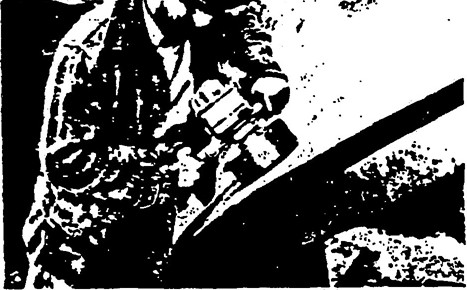
ILLUSTRATION No. 75
Note the well designed cup wheel guard.
The maximum safe operating speed for mounted wheels shall be determined by the following factors:
(See section 10 page 69 for explanation, and Tables 23 through 31 pages 72 through 85 for speeds.)
Explanatory Information
(NOT PART OF ANSI CODE)
Since the overhang of the mandrel of a mounted wheel is a factor in determining the maximum allowable operating speed, care should be taken to assure the overhang conforms to the limitations set forth in section 10 page 69.
55Type 27 and Type 28 wheels, because of their shape and usage, require specially designed adaptors. The back flange shall extend beyond the central hub or raised portion and contact the wheel to counteract the side pressure on the wheel in use. The adaptor nut which is less than the minimum one third diameter of wheel fits in the depressed side of wheel to prevent interference in side grinding and serves to drive the wheel by its clamping force against the depressed portion of the back flange. The variance in flange diameters, the adaptor nut being less than one third wheel diameter, and use of side pressure in wheel operation limits the use to reinforced organic bonded wheels.
Mounts which are affixed to the wheel by the manufacturer shall not be reused.
Type 27 and Type 28 wheels shall be used only with a safety guard located between wheel and operator during use. (See section 4.3.7.1. page 30 and Figure 39, page 39.)
Explanatory Information
(NOT PART OF ANSI CODE)
Type 27 and 28 wheels are designed for specific usage on right angle head grinders. Type 27 with flat outer area is better suited for notching and cutting operations as well as flat area grinding. Type 28 with saucer-shaped outer area is better suited for corner cleaning work. When these wheels are supplied with a throw-away type adaptor (mounting flange attached by the manufacturer), the adaptor should not be reused. It is important when mounting Type 27 and 28 wheels that proper contact is made with the larger back flange.
Flanges should be checked for flatness since a warped flange will cause vibration and possible wheel failure.
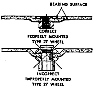
ILLUSTRATION No. 76
Types 27 and 28 wheels, because of their shape, require specially designed adaptors.
Type 27A cutting-off wheels are designed to be mounted by means of flat non-relieved flanges, having matching bearing surfaces not less than one-fourth the wheel diameter. See Illustration No. 77.
Explanatory Information
(NOT PART OF ANSI CODE)
Type 27A Wheels are designed for cutting-off on specially designed machines to provide side relief or clearance when used.
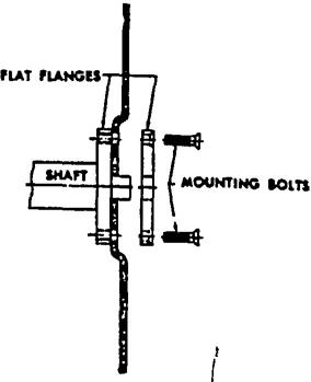
ILLUSTRATION No. 77
The Type 27A Wheel is mounted between flat won-relieved flanges of equal bearing surfaces.
Type 2 Cylinder wheels have diameter, wheel thickness and rim thickness dimensions. The wheel is mounted on the diameter with grinding performed on (wall) rim. The wheel is chucked or cemented directly to the machine face plate which is securely attached to machine spindle. The machine face plate shall be flat, concentric and at 90 degree angle as mounted to machine spindle. (See section 3 page 20, Table 2 page 25 for minimum thickness of machine face plate.) Cylinder wheels shall be used only on machines equipped with band type safety guards that conform to general specifications outlined in section 4.11 and 4.12 page 40.
Explanatory Information
(NOT PART OF ANSI CODE)
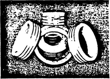
ILLUSTRATION No. 78
Examples of Type 2 cylinder wheels.
Segments individually chucked in suitable holding mechanisms to form a grinding unit shall be mounted in a manner prescribed by manufacturer of the chucking device. The safety guard should conform to that used for Cylinder Wheels, see section 6.17 and specifications outlined in section 4.11 and 4.12 page 40.
Explanatory Information
(NOT PART OF ANSI CODE)
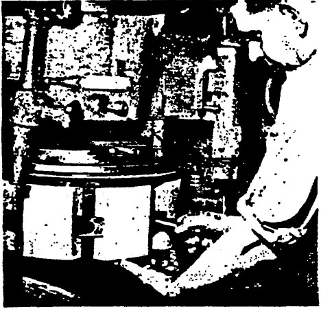
ILLUSTRATION No. 79
A segmental wheel assembly.
The maximum operating speed of each wheel shall be established by the wheel manufacturer. Table 20 page 59 indicates maximum surface feet per minute (SFPM) for various classes of wheels. (See Sec. 1 page 1.)
The number of revolutions per minute may be increased as the diameter of a wheel is reduced through wear, provided the original surface feet per minute (SFPM) is never exceeded. (The speed table on page 86 will be helpful in converting RPM to SFPM) It shall be the user’s responsibility not to exceed these maximum operating speeds.
Explanatory Information
(NOT PART OF ANSI CODE)
The maximum operating speeds established in Table 20 page 59 have proven satisfactory for the wheels as classified.
Under no condition should a wheel be operated faster than the maximum operating speed established by the manufacturer. This is the responsibility of the wheel user.
The maximum operating speed as determined by the manufacturer is dependent on the wheel shape and strength. The strength of a bonded abrasive wheel may be defined as the ability of the wheel to withstand rotational stress.
The maximum operating speed is not necessarily the most efficient grinding speed. Better results are frequently obtained at lower than maximum operating speeds.
All wheels classified for use under Table 20 page 59 of this Code shall be used on grinding machines designed and equipped in accordance with the following Code sections:
Explanatory Information
(NOT PART OF ANSI CODE)
The repeated references to other applicable Code Sections and Regulations are important. All designers of grinding machinery should be familiar with these sections. Their proper application has a direct relationship to the safe use of grinding wheels.
All grinding wheels shall be used in conformance with instructions given in:
and shall be handled, stored and inspected in accordance with Section 2 page 16.
Grinding wheels used at speeds higher than those shown in Table 20 page 59 shall be subject to the additional requirements outlined in Section 8 page 62 Special Speeds.
Explanatory Information
(NOT PART OF ANSI CODE)
The repeated references to other applicable Code Sections and Regulations are important. All users of grinding wheels should be familiar with these sections. Their proper application has a direct relationship to the safe use of grinding wheels.
58| Classification Number | Types of Wheels (See Section 1 for Definitions) | Inorganic Bonds | Organic Bonds | ||||
|---|---|---|---|---|---|---|---|
| Low Strength |
Medium Strength |
High Strength |
Low Strength |
Medium Strength |
High Strength |
||
| 1 | Type 1—Straight Wheels—except classifications 6, 7, 9, 10, 11, 12 and 13 below. Type 4—Taper Side Wheels |
OPERATING SPEED SHALL NOT EXCEED: | |||||
| SFPM | SFPM | SFPM | SFPM | SFPM | SFPM | ||
| Types 5, 7, 20, 21, 22, 23, 24, 25, 26 Recessed, Dovetailed and/or relieved wheels. (Except Classification 7 below.) | 5,500 | 6,000 | 6,500 | 6,500 | 8,000 | 9,500 | |
| Type 12—Dish Wheels Type 13—Saucer Wheels Types 16,17,18,19—Cones and Plugs |
|||||||
| 2 | Type 2—Cylinder Wheels including plate mounted, inserted nut and projecting stud—Segments | 5,000 | 5,500 | 6,000 | 5,000 | 6,000 | 7,000 |
| 3 | Cup Shape Tool Grinding Wheels (For Fixed Base Machines) Type 6—Straight Side Cups Type 11—Flaring Cups |
4,500 | 5,000 | 6,000 | 6,000 | 7,500 | 8,500 |
| 4 | Cup Shape Snagging Wheels (For Portable Machines) Type 6—Straight Side Cups Type 11—Flaring Cups |
4,500 | 5,500 | 6,500 | 6,000 | 8,000 | 9,500 |
| 5 | Abrasive Discs: Plate Mounted Inserted Nut and Projecting Stud: Solid or Segmental |
5,500 | 6,000 | 6,500 | 5,500 | 7,000 | 8,500 |
| 6 † | Reinforced Wheels Type 1 Max. Dia. 4” Max. Thickness ¼” |
Χ | Χ | Χ | 9,500 | 12,500 | 16,000 |
| Max. Dia. 10” Max. Thickness ½” |
Χ | Χ | Χ | 9,500 | 12,500 | 14,200 | |
| All Other Dias. and Thicknesses | Χ | Χ | Χ | 9,500 | 12,500 | 12,500 | |
| Reinforced Wheels—Types 27 and 28 Max. Dia. 9” Max. Thickness ½” |
Χ | Χ | Χ | 9,500 | 12,500 | 14,200 | |
| Max. Dia. 9”—Over ½” Thick | Χ | Χ | Χ | Χ | 9,500 | 11,000 | |
| 7 | Type 1 Wheels for Bench and Pedestal Grinders and Types 1 and 5 for Surface Grinders in following sizes only. 7” dia. up to 2” thick and up to 2” hole |
5,500 | 6,325 | 6,600 | 6,500 | 8,000 | 9,500 |
| 8” dia. up to 2” thick and up to 2” hole | 5,500 | 6,325 | 7,550 | 6,500 | 8,000 | 9,500 | |
| 8 | Diamond Wheels Cutting-Off—IAI, IAIR, IAIRS** |
Χ | Χ | 16,000 | Χ | Χ | 16,000 |
| Metal Bond | Χ | Χ | 12,000 | Χ | Χ | Χ | |
| Resin Bond | Χ | Χ | Χ | Χ | Χ | 9,500 | |
| Vitrified Bond | Χ | Χ | 6,500 | Χ | Χ | Χ | |
| 9 | Cutting Off Wheels Type 1 and 27A Larger than 16” dia., Including Reinforced Organic | Χ | Χ | Χ | 9,500 | 12,000 | 14,200 |
| 10 | Cutting Off Wheels Type 1 and 27A 16” dia., and Smaller—Including Reinforced Organic | Χ | Χ | Χ | 9,500 | 12,000 | 16,000 |
| 11 | Thread and Flute Grinding Wheels | 8,000 | 10,000 | 12,000 | 8,000 | 10,000 | 12,000 |
| 12 | Crankshaft and Camshaft Grinding Wheels | 5,500 | 8,000 | 8,500 | 6,500 | 8,000 | 9,500 |
| 13 | Type 1 Snagging Wheels 16” dia. and Larger, Organic Bond, Non Reinforced Used on Specially Designed Swing Frame and Mechanical Grinders | Χ | Χ | Χ | Χ | Χ | 12,500 |
| 14 | Internal Wheels—Type 1 and 5 Maximum dia. 6” |
5,500 | 8,000 | 8,500 | 6,500 | 8,500 | 9,500 |
| *Non-standard Shape †Classification 6 excludes cut-off wheels. **Standard Diamond Wheel Shapes. For definition see ANSI B74-1, identification code for Diamond Wheel Shapes. Note: For converting surface feet per minute (SFPM) to revolutions per minute (RPM) see Conversion Table page 36. Note: See section 3, page 20—General Machine Conditions: Section 4, page 27—Safety Guards; section 5, page 42—Flanges. |
|||||||
All wheels shall be tested in accordance with Table 21. In some cases the shape, size, construction, or use conditions of the wheel make the speed test impractical or unnecessary. Examples of wheels which need not be speed tested are:
Wheels less than 6” diameter;
Diamond wheels, metal and organic bonds;
Ball grinding wheels;
Segments, segmental disc wheels and disc wheels;
Regulating wheels (for centerless type grinders);
Mounted wheels.
Explanatory Information
(NOT PART OF ANSI CODE)
The test speed subjects a grinding wheel to significantly greater forces than does the safe maximum operating speed. This test establishes an adequate factor of safety provided the wheels are used in accordance with safe practices outlined in this Code and have not been altered, damaged or abused after speed testing.
The speed test does not justify operation of the wheel at higher than the safe maximum operating speed established by the wheel manufacturer. The maximum safe speed should never be exceeded because the additional tested strength covers other normal grinding stresses.
| Class of Wheel | Operating Speed Surface Feet Per Minute |
Minimum Test Factor* |
|---|---|---|
| Cutting-off Wheels | All speeds | 1.20 |
| All Bonds and Wheel Types (Except Cutting-off wheels) |
Up to 5,000 | 1.25 |
| All Bonds and Wheel Types (Except Cutting-off wheels) |
Faster than 5,000 | 1.50 |
| *Actual operating speed shall be multiplied by this test factor to establish minimum speed at which wheels shall be tested by the wheel manufacturer. | ||
The speed of the wheel spindle on grinding machines shall be frequently checked with suitable instruments, by competent user personnel, to make sure that the speed is correct for the size and type of wheels used. A suitable record of such speed checks should be maintained by the user.
Explanatory Information
(NOT PART OF ANSI CODE)
It is of special importance that portable air grinders should be checked to be sure that proper air pressure is maintained and that the machine governor mechanism is clean, in good operating condition, and functioning properly. This reference to air grinders is not intended to overlook the necessity for a regular check of the speed of wheel spindles on all types of grinding-machines. The user should assign this responsibility to competent personnel using equipment properly designed for such speed check purposes. The user should also keep a regular inspection record of such speed checks.
If the speed of the machine wheel spindle is adjustable to compensate for wheel wear, the speed adjustment shall be under the supervision and control of competent and authorized persons only.
Explanatory Information
(NOT PART OF ANSI CODE)
Certain machines are designed with adjustable speeds to permit maintenance of efficient surface speeds by increasing the wheel spindle speed to compensate for wheel wear. Special care must be exercised under proper supervision, to be certain that the present operating speed of the machine conforms to and does not exceed the peripheral speed in surface feet per minute as established for a new wheel. (See conversion table, page 86.)
61This section of the Code is designed to recognize the importance of continuing development in the science of grinding with bonded abrasive wheels. In such development it is well to restate the fact that the maximum safe operating speed marked on a wheel is not necessarily the most efficient grinding speed. Better results may be obtained at lower speeds. Constant reference to and a knowledge of the regulations of this Code will be helpful in planning the development of new equipment.
This section also defines the responsibilities of the Wheel Manufacturers; the Machine Builders (including one who converts, changes or otherwise alters a grinding or cut off machine from the design or purpose originally supplied by the builder); and the Users of wheels and machines. It shall be understood that these areas of responsibility apply to those wheels and machines operated at Special Speeds in excess of those listed in Table 20 page 59.
Explanatory Information
(NOT PART OF ANSI CODE)
The grinding or cutting-off operations performed with bonded abrasive wheels on many different types of machines are extremely important factors in the industrial productivity of our country. It is essential that wheels be operated and that machines be designed in accordance with the sections of this Code and that the users of wheels and machines observe the safety measures applicable to them in this Code. The cooperation of all three parties should materially aid in promoting the safe use, care and protection of abrasive wheels.
Wheels used on special applications at speeds higher than those listed in Table 20 (Section 7 page 58) shall only be used subject to the following three conditions: (A), (B) and (C), on effectively guarded, fully protected machines.
Explanatory Information
(NOT PART OF ANSI CODE)
When wheels are used at speeds in excess of standard speeds listed in Table 20 page 59 extra precautions should be observed to assure safe operation of the abrasive wheel.
The wheel manufacturer shall make certain that the wheels are of adequate strength, have been tested at a suitable overspeed in accordance with Section 7.1.4 page 60, and bear the wheel manufacturer’s approval of the higher speed. See Section 1.2.17 page 4 for definition of “The Wheel Manufacturer”.
Explanatory Information
(NOT PART OF ANSI CODE)
The wheel manufacturer should do such testing as he deems necessary to establish an adequate factor of safety before approving the wheel for the higher speed. The wheel should be marked that it has been approved for high speed application under specific conditions of use.
62The machine builder shall make certain at time of manufacture that the machine is of suitable design and adequately guarded for the operation in question. See Section 1.2.18 page 5 for definition of “The Machine Builder.”
It shall be the machine builder’s responsibility to consult with a wheel manufacturer to determine that a wheel for the special speed application can be manufactured and tested in accordance with the requirements established in Section 7.1.4 page 60.
Explanatory Information
(NOT PART OF ANSI CODE)
The machine builder should be sure the components of the machine such as spindle, bearings, guards, fianges, horsepower, etc., are adequate for the grinding operation in question.
Because of design and composition limitations, certain grinding wheels will not be suitable for special speed operations. It is, therefore, important that the machine builder and grinding wheel manufacturer cooperate to make certain a wheel of adequate strength can be manufactured for the operation in question.
The machine user shall make certain that the machine is operated with approved safety guards and that the machine is maintained in a satisfactory condition, as defined in Sections 3 and 4, page 20 and page 27. See Section 1.2.19 page 5 for definition of “the User”.
Explanatory Information
(NOT PART OF ANSI CODE)
The minimum guard requirements of Section 4 page 27 should be met. Where guard data for the wheel size and operating speed to be used is not available, requirements should be established by actual test. The machine user should also maintain machines in good condition for continuing safety (see Section 3 page 20).
It shall be the wheel manufacturer’s responsibility to speed test wheels required for special speeds and so identify them as follows:
Explanatory Information
(NOT PART OF ANSI CODE)
It is important that wheels used at special speeds be tested and identified for use at the proper maximum operating speed.
It shall be the wheel manufacturer’s responsibility to speed test wheels in accordance with Table 21 page 60 to determine their suitability for safe application. Some wheels that need not be speed tested are as listed in Section 7.1.4 page 60.
Explanatory Information
(NOT PART OF ANSI CODE)
Accepted industry practice for speed testing grinding wheels is outlined in Section 7.1.4 page 60.
It shall be the wheel manufacturer’s responsibility to identify wheels which may be run at special speeds.
Explanatory Information
(NOT PART OF ANSI CODE)
Wheels approved for special speed applications should have the special speed indicated on the wheels, blotters, accompanying tags, stickers or container.
It shall be the responsibility of the machine builder to design and construct those machine components which are concerned with the proper and safe operation of the grinding or cutting-off wheels for the speed and the type of operation for which the machine is intended. Particular attention shall be given to the design of the wheel safety guards, wheel fianges and wheel mounting spindle as indicated in the following paragraphs:
Explanatory Information
(NOT PART OF ANSI CODE)
The machine builder should decide upon the fitness of the machine for the proposed operation. If it becomes necessary or desirable to convert, change or alter the machine from the design or purpose for which it was originally made by the builder it is important that the components involved with the use of the abrasive wheel be designed in accordance with the appropriate sections of this Code.
63If an existing machine is to be adapted for use at a special speed, the general machine conditions of Section 3 page 20 shall be observed and all component parts of the grinding machine shall be checked and, if necessary, modified or adjusted prior to operating at the special speed.
Explanatory Information
(NOT PART OF ANSI CODE)
It is important to remember that the grinding wheel is only one part of the grinding operation. When the speed of the wheel is increased, changes may be necessary in the machine (bearings, table traverse rates, guards, sensing devices, power, etc.), so that the entire unit will operate safely at the special speed.
Grinding and cutting off machines shall be equipped with safety guards in conformance with the requirements contained in Section 4 page 27 when applicable. When the operation is beyond the conditions for which guards in Section 4 page 27 were designed, the machine builder shall establish by test or calculation the adequacy of the guard.
Explanatory Information
(NOT PART OF ANSI CODE)
Guards built in conformance with instructions contained in Section 4 page 27 will have a safety factor which satisfies good engineering practice. When speeds in excess of those shown in Section 4 page 27 are used, either a stronger guard material or thicker guard members must be used. The increase in strength should be sufficient to maintain the proper safety factor.
Flanges shall be of such design as to satisfactorily transmit the driving torque from the spindle to the grinding wheel and conform to all requirements of Section 5 page 42.
Explanatory Information
(NOT PART OF ANSI CODE)
The driving torque is transmitted from the spindle through the flange to the wheel. Therefore, the minimum bearing area specified in Section 5 page 42 may be inadequate in these cases. The machine builder should determine by test that his design is adequate to perform its intended operation.
The user shall be responsible for the proper handling, storage, and inspection of grinding wheels after receipt, in accordance with the requirements of Section 2 page 16.
It shall be the responsibility of the user to maintain his grinding equipment in a safe operating condition at all times. Rules of safe operation of this equipment submitted by the machine builder shall be observed, as well as those rules specified in other sections of this Code.
When an existing machine is altered by the user to operate at special speeds, the user shall assume all of the responsibility of a machine builder as outlined in Section 3 page 20.
The user shall fully inform all operating personnel that only wheels identified for operation at special speeds shall be used and that at no time shall the maximum speed of the wheel be exceeded.
Protection to operating personnel, as well as adjacent areas, shall be maintained at all times.
Explanatory Information
(NOT PART OF ANSI CODE)
The maximum operating speed as determined by the manufacturer is dependent on the wheel shape and strength. The strength of a bonded abrasive wheel may be defined as the ability of the wheel to withstand rotational stress.
Under no condition should a wheel be operated faster than the maximum operating speed established by the manufacturer. This is the responsibility of the wheel user.
It is an important responsibility of the user to maintain grinding machines in a safe operating condition. Machine builders usually issue rules for the safe operation of their equipment or fasten warning signs to their machines calling attention to areas that could be unsafe if the rules or signs are disregarded. The user should recognize the importance of instructing personnel concerning these safety warnings.
Furthermore, grinding machines are usually designed to perform certain specific operations. It is strongly recommended that the machines be used only on those types of operations for which they are designed.
64It shall be the user’s responsibility to adhere to all parts of Section 2 page 16.
Explanatory Information
(NOT PART OF ANSI CODE)
It is important that all wheels be handled and stored correctly, and inspected carefully. It is recommended that wheels for special high speeds be stored in a separate or special area so that personnel will be aware they are for special applications.
It shall be the user’s responsibility to see that the machine is maintained in such condition that all requirements of Section 3 page 20 will continue to be adequate.
Explanatory Information
(NOT PART OF ANSI CODE)
It is important that the maintenance of the machine be such that the equipment remains in the same condition as originally furnished.
It shall be the user’s responsibility to maintain the guards and other protection devices in good condition. The user shall also make provision for adequate protection of the personnel in the operating area. (See Section 4.5.2 page 32.)
Explanatory Information
(NOT PART OF ANSI CODE)
When operating at special high speeds, the pieces of an accidentally broken wheel will have more force than those broken at lower speeds. It is, therefore, imperative that all guards and protective devices be maintained in good condition and correctly replaced when removed. It is also important that adjacent personnel be protected by barriers, booths or segregated work areas.
It shall be the user’s responsibility to maintain flanges in good condition according to Section 5 page 42.
Explanatory Information
(NOT PART OF ANSI CODE)
A primary function of flanges is to transfer the machine power to the abrasive wheel and grinding operation. It is therefore important that flanges be maintained as defined in Section 5 page 42. Flanges which are worn, warped or sprung can contribute to wheel breakage.
It shall be the users responsibility to see that all rules of Section 6 page 52 which apply to the particular operation are observed.
Explanatory Information
(NOT PART OF ANSI CODE)
It is extremely important that all wheels, regardless of speed of operation or the type of machine involved, be inspected before mounting (see Section 6.1 page 52) and that all rules for safe mounting practices be observed.
It shall be the user’s responsibility to see that all General Operating Rules (see Section 9 page 66) that are applicable to the special high speed operation are observed. It shall also be the user’s responsibility to follow any special operating instructions furnished by the machine builder.
Explanatory Information
(NOT PART OF ANSI CODE)
In some instances the machine builder will provide special operating instructions and/or place warning signs on his machines. These, as well as the general operating rules listed in Section 9 page 66, should be followed to insure a safe grinding operation.
65Competent persons shall be assigned to the mounting, care, and inspection of grinding wheels and machines.
The grinding wheel operator shall be fully instructed in the use, care and protection of grinding wheels as defined in this Code.
Explanatory Information
(NOT PART OF ANSI CODE)
More efficient grinding and a reduction of wheel breakages will result when the user insists that only personnel with mechanical aptitude and a good knowledge of the contents of this Code be assigned to the mounting, care, inspection and operation of grinding wheels and machines.
If a grinding wheel is broken, a careful investigation shall be made by the user to determine and correct the cause.
Explanatory Information
(NOT PART OF ANSI CODE)
Should a grinding wheel be broken in service, an investigation must be made immediately by the user to be sure that any conditions at variance with the requirements contained in this code and state laws are corrected. This will help determine the cause of the breakage so that a recurrence of the trouble can be prevented. Assistance in such an investigation may be obtained from the machine maker and the wheel manufacturer.
Before mounting a wheel, it shall be determined that the machine speed does not exceed the maximum safe operating speed for the wheel as established by the wheel manufacturer. Under no circumstances shall a wheel be mounted on a machine on which the RPM exceeds the maximum safe RPM recommended for the wheel.
Explanatory Information
(NOT PART OF ANSI CODE)
On some variable speed machines, spindle speed is governed by an interlock with the guard or some other device that allows the RPM to be increased as wheel diameter decreases. Care must be exercised to determine that such devices are in good working order, to prevent the possibility of over-speeding and wheel breakage.
After mounting a wheel, care should be taken to see that the safety guard is properly positioned before starting the wheel.
All grinding wheels shall be run at operating speed with safety guard in place or in a protected enclosure for at least one minute before applying work, during which time no one shall stand in front of or in line with the wheel. (See Section 4 page 27.)
Explanatory Information
(NOT PART OF ANSI CODE)
This regulation provides for the safety of the operator and others should there have been damage to the wheel or malfunction of the machine from any cause.
Wheels should be rebalanced by the user when and as often as necessary.
Explanatory Information
(NOT PART OF ANSI CODE)
Out of balance wheels set up vibrations which can result in marred work surfaces, machine damage and also cause stresses which could result in wheel failure. On most machines, the wheels can be rebalanced by truing.
66Out of truth wheels shall be trued by a competent person. Wheels out of balance which cannot be balanced by truing or dressing, shall be removed from the machine. (See Fig. No. 52.)
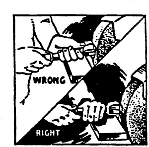
FIGURE NO. 52
The correct and incorrect method of dressing a wheel.
Explanatory Information
(NOT PART OF ANSI CODE)
Truing a wheel corrects any out of truth condition in the wheel.
Dressing a wheel alters its cutting action or shape.
A common method of dressing a wheel used in off-hand operations is shown in Fig. No. 52. Note that the dresser should be supported on a work rest, and that the work rest should be adjusted away from the wheel so that the heel of the dresser may hook over the work rest and be guided by it as the dresser is moved evenly across the wheel face.
When shutting down a wet grinding operation, the coolant should first be shut off and the wheel allowed to rotate until coolant has been spun out.
The strength of organic bonded wheels can be affected by coolants. Therefore, the concentration and alkalinity of the coolant should be checked regularly and adjusted accordingly.
Explanatory Information
(NOT PART OF ANSI CODE)
Uneven accumulation of coolant can cause excessive out of balance in a wheel.
The concentration and alkalinity of coolants determines the degree to which they affect organic bonded wheels. To avoid injurious affect upon these wheels, it is important to follow the directions of the coolant manufacturer.
Side grinding shall only be performed with wheels designed for this purpose. Grinding on the flat sides of straight wheels is often hazardous and should not be allowed on such operations when the sides of the wheel are appreciably worn thereby or when any considerable or sudden pressure is brought to bear against the sides.
Explanatory Information
(NOT PART OF ANSI CODE)
Peripheral grinding wheels should not be used for side grinding because of insufficient support to withstand the pressures exerted. Wheels designed for side grinding such as abrasive discs are mounted with one flat side against a suitable steel machine plate to safely withstand side pressure.
The machine spindle bearings shall be properly lubricated to prevent heating which might cause damage to the grinding wheel.
Explanatory Information
(NOT PART OF ANSI CODE)
Improperly lubricated spindle bearings will cause the mounting spindle to expand because of heat generated thus exerting a stress in the arbor hole area.
67All spindles, adaptors, flanges or other machine parts on which wheels fit, shall be periodically inspected and maintained to size. (See Section 3 page 20.)
On offhand grinding machines (see sec. 1.3.6, page 6) work rests shall be used to support the work. They shall be of rigid construction and designed to be adjustable to compensate for wheel wear.
Work rests shall be kept adjusted closely to the wheel with a maximum opening of ½” to prevent the work from being jammed between the wheel and the rest, which may cause wheel breakage. The work rest shall be securely clamped after each adjustment. The adjustment shall not be made with the wheel in motion.
Explanatory Information
(NOT PART OF ANSI CODE)
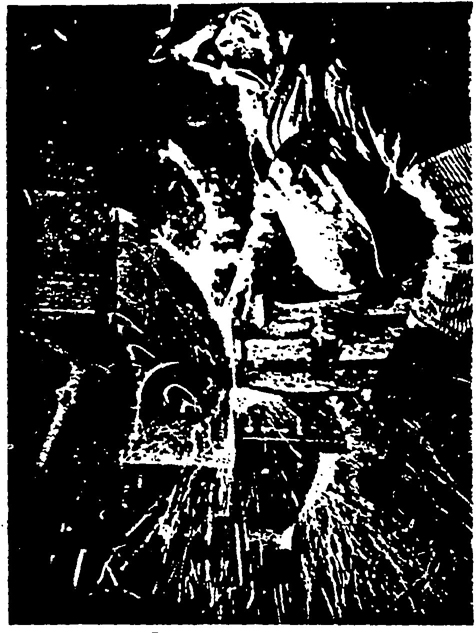
ILLUSTRATION No. 80
This floor stand grinder has a work rest which is property adjusted. Note the provisions for work-rest adjustment.
Large hole inorganic bonded wheels (those with hole in excess of ¼ of the wheel diameter) should not be used on snagging or other heavy duty operations.
Explanatory Information
(NOT PART OF ANSI CODE)
Since the strength of a grinding wheel decreases as its diameter approaches its hole size, it is not advisable to use large hole inorganic wheels for rough grinding operations since ample cross section required for strength is not maintained throughout the life of the wheel.
The fact that large hole inorganic bonded wheels cannot be manufactured with reinforcing media near the hole makes them unsuitable for rough grinding operations.
68The maximum safe operating speed for mounted wheels shall be determined by the following four factors:
Taking the first three factors noted above into consideration, look up the maximum safe operating speed in the corresponding Tables 23 through 31 page 72 through page 85, The overhangs indicated on the charts are for unthreaded mandrels. Threaded mandrels will take the same speed as the ½ inch overhang of the unthreaded mandrel.
Tables 23 through 31 page 72 through page 85 are set up for medium and high strength wheels. If the specification indicates a low strength wheel consult the wheel manufacturer for speeds. In no case shall the maximum operating speed recommended by the manufacturer be exceeded.
Exception: Under certain ideal conditions of truth and balance where the operation is fully guarded, it may be permissible to operate at a speed higher than the indicated maximum safe operating speed, provided the speed shown in section 10.2 page 70, is not exceeded.
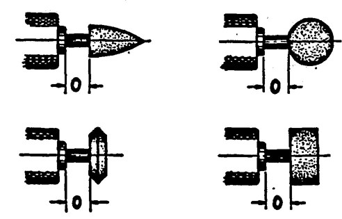
FIGURE NO. 53
Sketches defining everhand dimension “O” See Tables 23 through 31.
Explanatory Information
(NOT PART OF ANSI CODE)
Maximum safe speeds for mounted wheels are generally limited by the size and shape of the wheel, the mandrel material and diameter, and the distance from the mounting chuck to the abrasive body (overhang).
Due to the size of some mounted wheels, it is necessary to reduce the size of the mandrel where it enters the wheel. These are called tapered mandrels. It will be noted however, that the resistance to bending or whipping due to speed is dependent on the size of the mandrel at the point where it is chucked, so that the size of the mandrel for speed purposes will be the diameter of the chucked section.
As threading reduces the effective diameter of the mandrel, mounted wheels with threaded mandrels require lower operating speeds than the same size unthreaded mandrels. Because these mandrels are usually short and held closely in the chuck, the tables give only the speeds for ½ inch overhang.
Tables 23 to 31 page 72 through page 85 indicate the maximum operating speeds for various standard mounted wheels in combination with several standard mandrel sizes and various overhangs. For many common combinations, the maximum operating speeds can be read directly from the tables. For intermediate wheel and mandrel sizes and overhangs not shown the maximum operating speed can be determined by interpolation.
If it is found that the desired combination of conditions would result in operation beyond the maximum speed, a slight change in any one of the following conditions may be all that is necessary to eliminate the danger of operating over the maximum safe speed. Such corrective steps are:
1. For a given shape, reducing the size of the wheel (either diameter or thickness, or both) will raise the maximum speed.
2. Increasing the diameter of the mandrel will raise the maximum speed.
3. Reducing the overhang (pushing the mandrel back into the chuck) will raise the maximum speed.
69Table 22 shows the maximum operating speed for various diameters of mounted wheels. This speed shall not be exceeded even though higher speeds than the maximum safe operating speed are used under the exception in Section 10.1 page 69.
| Outside Diameter of Wheel Inches | Maximum Speed (R.P.M.) |
|---|---|
| ⅛ | 305,500 |
| ¼ | 152,800 |
| 5/16 | 122,200 |
| [Illegible Text Omitted on Page 70] | 101,900 |
| 7/16 | 87,310 |
| ½ | 76,390 |
| ⅝ | 61,120 |
| 11/16 | 55,560 |
| ¾ | 50,930 |
| 13/16 | 47,010 |
| [Illegible Text Omitted on Page 70] | 43,650 |
| 13/16 | 40,740 |
| 1 | 38,200 |
| 1⅛ | 33,950 |
| 1¼ | 30,560 |
| 1⅜ | 27,780 |
| 1½ | 25,470 |
| 1 ⅝ | 23,520 |
| 1 ¾ | 21,830 |
| 2 | 19,100 |
Explanatory Information
(NOT PART OF ANSI CODE)
Tables 23 to 31 page 72 through page 85 are based on the several factors which affect the maximum safe operating speed, however, there is a limiting speed beyond which no mounted wheel should be run due to the inherent strength of the abrasive body itself. This is the speed set up in Table 22. No matter what factors of wheel size, shape or specification, mandrel size, overhang, or machine conditions are changed, the speeds in Table 22 shall not be exceeded.
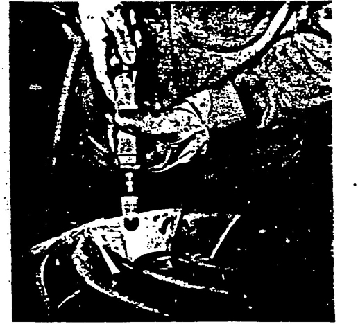
ILLUSTRATION No. 81
A mounted wheel being used to finish a die
Pressure between the wheel and the work shall not be so heavy that excessive springing of the mandrel will result.
Explanatory Information
(NOT PART OF ANSI CODE)
Work pressure, if excessive, can be the cause of trouble and a source of danger, through bending or fracture of the mandrel. If there is burning of the work or excessive reduction in mandrel speed, it is quite likely that excessive pressure is being used. A freer cutting wheel specification may permit the desired rate of stock removal without excessive pressure.
70| Shape No. | Wheel Diam. Inches | Wheel Thickness Inches | ½″ Overhang & Thd. Mdls. | Overhang — Dimension O* |
|||
|---|---|---|---|---|---|---|---|
| 1″ | 1½″ | 2″ | 2½″ | ||||
| W 141 W 142 |
[Illegible Text Omitted on Page 72] [Illegible Text Omitted on Page 72] |
[Illegible Text Omitted on Page 72] ¼ |
93,750 93,750 |
53,250 53,250 |
37,500 37,500 |
25,500 25,500 |
16,500 16,500 |
| W 143 W 144 W 145 W 146 |
⅛ ⅛ ⅛ ⅛ |
⅛ ¼ ⅜ ½ |
93,750 93,750 88,500 81,000 |
53,250 53,250 49,500 43,750 |
37,500 37,500 35,250 31,500 |
25,500 25,500 24,000 22,500 |
16,500 16,500 15,750 15,000 |
| W 147 W 148 W 149 |
3/32 3/32 3/32 |
1/32 1/16 ¼ |
93,750 93,750 90,750 |
53,250 53,250 50,250 |
37,500 37,500 36,000 |
25,500 25,500 24,750 |
16,500 16,500 15,750 |
| W 150 W 151 W 152 W 153 W 154 |
3/16 3/16 3/16 3/16 3/16 |
1/16 ⅛ ¼ ⅜ ½ |
93,750 93,750 83,250 73,500 66,000 |
53,250 53,250 47,250 42,000 38,250 |
37,500 37,500 33,000 28,500 25,500 |
25,500 25,500 23,250 21,000 18,750 |
16,500 16,500 15,000 13,500 12,750 |
| W 155 | [Illegible Text Omitted on Page 72] | ¼ | 78,000 | 44,250 | 30,750 | 21,750 | 14,250 |
| W 156 W 157 W 158 W 159 W 160 W 161 W 162 |
¼ ¼ ¼ ¼ ¼ ¼ ¼ |
1/32 1/16 ⅛ 3/16 ¼ 5/16 ⅜ |
93,750 93,750 93,750 78,000 69,000 66,000 57,000 |
53,250 53,250 53,250 44,250 42,000 39,750 34,500 |
37,500 37,500 37,500 30,750 27,750 24,750 23,250 |
25,500 25,500 25,500 21,750 18,750 17,250 16,500 |
16,500 16,500 16,500 14,250 13,500 12,750 11,250 |
| W 165 W 166 W 167 W 168 W 169 W 170 W 171 |
5/16 5/16 5/16 5/16 5/16 5/16 5/16 |
1/16 ⅛ ¼ 5/16 ⅜ ½ ¾ |
93,000 84,750 61,500 56,250 48,000 39,750 27,750 |
51,750 48,750 39,000 33,750 28,500 26,250 19,500 |
37,500 28,500 24,750 22,500 20,250 16,500 13,500 |
25,500 19,500 18,000 16,500 15,000 12,750 10,500 |
16,500 14,250 12,000 12,000 11,250 9,750 8,250 |
| W 172 W 173 W 174 W 175 W 176 |
⅜ ⅜ ⅜ ⅜ ⅜ |
1/16 ⅛ ¼ ⅜ ½ |
85,500 71,250 54,000 41,250 33,750 |
48,750 46,500 32,250 24,000 21,000 |
33,750 30,000 21,000 18,000 15,750 |
24,000 19,500 15,000 12,750 12,000 |
15,000 12,750 10,500 9,750 9,000 |
| *See Figure 53, Page 69. | |||||||
| Shape No. | Wheel Diam. Inches | Wheel Thickness Inches | ½″ Overhang & Thd. Mdls. | Overhang — Dimension O* | |||
|---|---|---|---|---|---|---|---|
| 1″ | 1½″ | 2″ | 2½″ | ||||
| W 143 W 144 W 145 W 146 |
⅛ ⅛ ⅛ ⅛ |
⅛ ¼ ⅜ ½ |
105,000 105,000 105,000 105,000 |
64,500 64,500 64,500 64,500 |
46,650 46,650 46,650 46,650 |
32,400 32,400 32,400 32,400 |
21,370 21,370 21,370 21,370 |
| W 151 W 152 W 153 W 154 |
3/16 3/16 3/16 3/16 |
⅛ ¼ ⅜ ½ |
105,000 105,000 80,850 70,500 |
64,500 64,500 52,500 45,600 |
46,650 46,650 37,500 31,500 |
32,400 32,400 26,250 21,970 |
21,370 21,370 17,620 15,220 |
| W 157 W 158 W 159 W 160 |
¼ ¼ ¼ ¼ |
1/16 ⅛ 3/16 ¼ |
123,000 105,000 92,400 81,370 |
65,625 64,500 57,370 51,000 |
47,770 46,650 39,370 34,120 |
33,150 32,400 27,900 24,000 |
21,750 21,370 18,900 16,870 |
| W 161 W 162 W 163 W 164 |
¼ ¼ ¼ ¼ |
5/16 ⅜ ½ ¾ |
77,250 68,400 60,000 45,900 |
45,970 42,370 38,020 30,000 |
30,900 28,870 26,250 21,750 |
22,500 20,850 18,750 15,900 |
16,120 15,000 13,870 11,850 |
| W 165 W 166 W 167 W 168 |
5/16 5/16 5/16 5/16 |
1/16 ⅛ ¼ 5/16 |
107,400 96,970 75,000 68,400 |
62,470 57,000 45,750 41,770 |
41,250 35,620 31,120 28,650 |
29,250 25,120 22,500 21,000 |
20,250 18,000 15,750 15,000 |
| W 169 W 170 W 171 |
5/16 5/16 5/16 |
⅜ ½ ¾ |
61,650 52,500 37,120 |
37,720 33,000 25,500 |
27,000 23,020 18,750 |
19,870 16,650 14,620 |
14,250 12,600 10,020 |
| W 172 W 173 W 174 W 175 |
⅜ ⅜ ⅜ ⅜ |
1/16 ⅛ ¼ ⅜ |
99,370 87,600 69,000 54,000 |
59,250 53,250 41,250 33,000 |
41,020 35,250 27,750 24,150 |
29,250 24,750 20,400 18,000 |
20,250 17,250 15,000 13,500 |
| W 176 W 177 W 178 |
⅜ ⅜ ⅜ |
½ ¾ 1 |
45,370 33,750 26,250 |
28,500 23,250 18,750 |
21,000 17,620 14,250 |
15,900 13,650 10,870 |
12,150 10,350 8,250 73 |
| W 181 W 182 W 183 W 184 |
½ ½ ½ ½ |
1/16 ⅛ ¼ ⅜ |
76,390 73,500 51,750 41,020 |
55,500 43,650 31,870 26,400 |
36,750 29,100 22,500 19,500 |
25,500 20,770 17,250 15,000 |
17,850 15,450 12,900 11,400 |
| W 185 W 186 W 187 |
½ ½ ½ |
½ ¾ 1 |
34,500 26,250 20,620 |
22,500 17,400 13,870 |
16,870 12,750 10,120 |
13,120 9,750 7,870 |
9,900 8,020 6,370 |
| W 190 W 191 W 192 W 193 |
⅝ ⅝ ⅝ ⅝ |
1/16 ⅛ ¼ ⅜ |
61,120 58,870 43,120 32,250 |
48,000 34,500 27,370 23,020 |
31,500 25,120 19,870 16,500 |
22,650 18,900 15,220 12,520 |
16,870 14,250 11,620 9,750 |
| W 194 W 195 W 196 |
⅝ ⅝ ⅝ |
½ ¾ 1 |
29,400 22,120 17,620 |
19,120 14,250 11,620 |
13,500 10,120 8,100 |
10,500 7,650 6,150 |
8,250 6,150 5,100 |
| W 199 W 200 W 201 W 202 |
¾ ¾ ¾ ¾ |
1/16 ⅛ ¼ ⅜ |
50,930 50,930 38,250 30,600 |
44,770 33,520 24,370 19,500 |
30,000 23,850 17,400 13,500 |
21,750 17,850 13,270 10,120 |
15,750 13,350 9,970 7,800 |
| W 203 W 204 |
¾ ¾ |
½ ¾ |
25,500 18,900 |
15,900 12,000 |
10,870 8,400 |
8,250 6,220 |
6,600 5,250 |
| W 210 W 211 W 212 W 213 |
⅞ ⅞ ⅞ ⅞ |
1/16 ⅛ ¼ ⅜ |
43,650 43,650 33,750 27,000 |
35,250 27,900 20,400 16,870 |
25,720 20,400 14,400 11,250 |
18,900 15,820 11,020 8,250 |
14,320 12,220 9,000 6,600 |
| W 215 W 216 |
1 1 |
⅛ ¼ |
38,200 30,520 |
24,900 18,600 |
18,000 12,750 |
13,870 9,520 |
10,500 7,500 |
| *See Figure 53, Page 69. | |||||||
| Shape No. | Wheel Diam. Inches | Wheel Thickness Inches | ½″ Overhang & Thd. Mdls. | Overhang — Dimension O* | |||
|---|---|---|---|---|---|---|---|
| 1″ | 1½″ | 2″ | 2½″ | ||||
| W 158 W 159 W 160 W 161 |
¼ ¼ ¼ ¼ |
⅛ 3/16 ¼ 5/16 |
121,500 112,500 103,500 93,750 |
66,750 63,000 60,000 58,120 |
48,000 47,250 44,250 42,750 |
36,000 34,650 33,000 31,870 |
26,250 25,120 24,000 22,500 |
| W 162 W 163 W 164 |
¼ ¼ ¼ |
⅜ ½ ¾ |
89,250 78,750 62,250 |
56,250 52,500 39,750 |
41,250 39,000 30,000 |
30,000 28,870 23,250 |
21,750 20,620 16,500 |
| W 166 W 167 W 168 W 169 |
5/16 5/16 5/16 5/16 |
⅛ ¼ 5/16 ⅜ |
118,500 100,500 93,000 87,370 |
65,250 58,500 57,000 55,350 |
47,250 43,500 42,000 40,870 |
35,250 32,620 30,750 28,880 |
25,500 23,250 22,120 21,000 |
| W 170 W 171 |
5/16 5/16 |
½ ¾ |
76,500 57,000 |
47,250 37,500 |
34,500 27,750 |
25,500 21,750 |
18,750 15,750 |
| W 173 W 174 W 175 W 176 |
⅜ ⅜ ⅜ ⅜ |
⅛ ¼ ⅜ ½ |
101,900 98,850 81,750 66,750 |
65,250 57,750 50,620 43,120 |
46,500 42,750 36,750 31,350 |
34,500 32,250 27,750 23,620 |
24,750 23,250 20,250 17,400 |
| W 177 W 178 |
⅜ ⅜ |
¾ 1 |
54,000 42,000 |
36,000 29,250 |
26,250 22,500 |
20,250 17,250 |
15,000 12,900 |
| W 182 W 183 W 184 W 185 |
½ ½ ½ ½ |
⅛ ¼ ⅜ ½ |
76,390 75,000 57,750 49,870 |
56,250 47,400 39,750 33,750 |
39,870 33,370 29,250 25,500 |
29,250 24,900 21,750 19,500 |
21,750 18,750 15,750 14,620 |
| W 186 W 187 W 188 W 189 |
½ ½ ½ ½ |
¾ 1 1½ 2 |
39,000 32,250 22,870 17,250 |
28,120 23,250 17,620 13,500 |
21,370 18,370 13,870 10,500 |
15,750 13,500 11,250 8,620 |
12,000 10,500 ..... ..... |
| W 191 W 192 W 193 W 194 |
⅝ ⅝ ⅝ ⅝ |
⅛ ¼ ⅜ ½ |
61,120 61,120 52,500 44,400 |
51,370 43,500 34,870 31,120 |
36,370 30,750 25,500 23,400 |
27,000 23,400 18,750 18,000 |
20,250 18,000 15,000 13,500 75 |
| W 195 W 196 W 197 W 200 W 201 W 202 W 203 |
⅝ ⅝ ⅝ ¾ ¾ ¾ ¾ |
¾ 1 2 ⅛ ¼ ⅜ ½ |
34,500 25,870 14,770 50,930 50,930 45,750 39,750 |
24,000 18,900 11,770 48,750 37,500 31,500 27,370 |
18,370 15,000 8,700 33,750 27,900 24,370 20,620 |
14,250 11,620 7,270 25,500 21,370 18,000 15,900 |
10,500 9,370 ..... 19,500 16,500 13,870 12,000 |
| W 204 W 205 W 206 W 207 |
¾ ¾ ¾ ¾ |
¾ 1 1¼ 1½ |
29,250 24,750 19,500 16,500 |
20,250 17,250 14,250 12,370 |
15,000 12,750 11,620 9,750 |
12,000 10,500 9,000 7,870 |
9,370 8,620 6,750 ..... |
| W 208 | ¾ | 2 | 12,750 | 9,370 | 7,500 | 6,000 | ..... |
| W 211 W 212 W 213 |
⅞ ⅞ ⅞ |
⅛ ¼ ⅜ |
43,650 43,650 42,370 |
43,650 34,500 28,120 |
31,870 25,870 21,370 |
24,000 19,870 16,500 |
18,370 14,620 12,370 |
| W 215 W 216 W 217 W 218 |
1 1 1 1 |
⅛ ¼ ⅜ ½ |
38,200 38,200 38,200 32,700 |
38,200 33,750 27,000 22,120 |
31,120 24,750 19,870 16,870 |
23,620 19,120 15,750 12,900 |
18,000 14,250 12,000 10,350 |
| W 219 W 220 W 221 W 222 |
1 1 1 1 |
¾ 1 1½ 2 |
25,120 19,500 13,120 9,000 |
17,620 14,250 9,370 7,120 |
12,900 11,250 7,120 5,620 |
9,900 8,620 6,000 4,870 |
8,400 7,120 ..... ..... |
| W 225 W 226 W 227 W 228 |
1¼ 1¼ 1¼ 1¼ |
¼ ⅜ ½ ¾ |
30,560 30,560 27,750 20,620 |
28,870 22,120 19,120 14,620 |
21,220 16,350 13,950 11,020 |
16,270 12,750 10,650 8,770 |
12,300 10,270 8,700 7,120 |
| W 229 W 230 W 231 W 232 |
1¼ 1¼ 1¼ 1¼ |
1 1¼ 1½ 2 |
16,500 13,270 10,270 7,500 |
12,000 9,150 7,270 6,000 |
8,620 6,970 6,000 4,870 |
6,900 5,700 5,100 4,500 |
5,770 ..... ..... ..... |
| W 235 W 236 W 237 W 238 |
1½ 1½ 1½ 1½ |
¼ ½ 1 1½ |
25,470 25,470 15,750 9,900 |
24,900 18,750 11,250 6,970 |
18,900 13,870 7,870 5,470 |
15,150 10,500 6,370 4,870 |
11,770 8,620 5,620 |
| *See Figure 53, Page 69. | |||||||
| Shape No. | Wheel Diameter Inches | Wheel Thickness Inches | ½″ Overhang & Thd. Mdls. | Overhang — Dimension O* | ||||||
|---|---|---|---|---|---|---|---|---|---|---|
| 1″ | 1½″ | 2″ | 2½″ | 3″ | 4″ | 5″ | ||||
| W 176 W 177 W 178 W 179 |
½ ½ ½ ½ |
½ ¾ 1 1 ¼ |
81,000 66,000 55,200 45,750 |
54,379 46,500 40,500 33,750 |
42,000 32,250 30,000 25,720 |
33,000 27,370 23,250 19,720 |
25,500 21,000 17,250 15,300 |
20,400 16,800 13,800 12,240 |
13,260 10,920 8,970 7,960 |
9,550 7,860 6,460 5,730 |
| W 182 W 183 W 184 W 185 |
½ ½ ½ ⅓ |
⅓ ¼ ⅔ ½ |
76,390 76,390 71,250 61,500 |
62,400 54,750 47,620 42,000 |
45,750 40,500 35,020 31,500 |
35,400 31,120 27,000 24,000 |
27,520 24,000 20,850 18,370 |
22,020 19,200 16,680 14,700 |
14,310 12,480 10,840 9,560 |
10,300 8,990 7,800 6,880 |
| W 186 W 187 W 188 W 189 |
½ ½ ½ ½ |
¾ 1 1½ 2 |
51,000 40,500 30,370 24,000 |
36,370 30,000 24,000 18,750 |
27,750 24,000 18,900 15,000 |
21,220 18,750 15,000 12,150 |
16,120 14,250 12,000 9,900 |
12,900 11,400 9,600 7,920 |
8,390 7,410 6,240 5,150 |
6,040 5,340 4,490 3,710 |
| W 190 W 191 W 192 W 193 |
⅝ ⅝ ⅝ ⅝ |
1/16 ⅛ ¼ ⅜ |
61,120 61,120 61,120 61,120 |
61,120 60,000 51,750 45,000 |
48,000 44,250 38,400 33,370 |
31,500 34,500 29,770 25,870 |
29,020 27,000 23,250 20,100 |
23,220 21,600 18,680 16,080 |
15,090 14,040 12,140 10,450 |
10,800 10,110 8,740 7,520 |
| W 194 W 195 W 196 W 197 |
⅝ ⅝ ⅝ ⅝ |
½ ¾ 1 2 |
56,400 46,500 35,250 21,000 |
39,750 32,400 27,000 16,500 |
29,400 24,900 21,300 12,900 |
22,720 19,720 16,870 10,870 |
17,400 15,370 13,120 8,700 |
13,920 12,300 10,500 6,960 |
9,050 8,000 6,830 4,520 |
6,520 5,760 4,920 3,250 |
| W 198 | ⅝ | 2½ | 16,500 | 12,900 | 10,870 | 8,700 | 7,000 | 5,600 | 3,640 | 2,620 |
| W 201 W 202 W 203 W 204 |
¾ ¾ ¾ ¾ |
¼ ⅜ ½ ¾ |
50,930 50,930 50,930 42,750 |
50,930 44,100 36,370 30,750 |
38,100 32,400 27,750 23,250 |
29,020 25,120 21,750 18,000 |
22,500 19,350 16,870 14,020 |
18,000 15,480 13,500 11,220 |
11,700 10,060 8,780 7,290 |
8,420 7,240 6,320 5,250 |
| W 205 W 206 W 207 W 208 |
¾ ¾ ¾ ¾ |
1 1 ¼ 1 ½ 2 |
34,500 28,720 24,000 18,750 |
25,870 21,520 18,520 15,370 |
19,500 17,020 14,620 12,000 |
15,000 13,500 12,000 9,900 |
12,000 10,800 9,900 8,000 |
9,600 8,640 7,920 6,400 |
6,240 5,620 5,150 4,160 |
4,490 4,050 3,710 3,000 |
| W 209 | ¾ | 2½ | 15,000 | 12,150 | 10,500 | 8,400 | 6,800 | 5,440 | 3,540 | 2,550 |
| W 211 | ₖ | ¼ | 43,650 | 43,650 | 42,900 | 33,000 | 26,250 | 21,000 | 13,650 | 9,820 77 |
| W 212 W 213 |
⅞ ⅞ |
¼ [Illegible Text Omitted on Page 78] |
43,650 43,650 |
43,650 40,870 |
35,100 29,400 |
27,600 23,400 |
21,370 18,370 |
17,100 14,700 |
11,120 9,560 |
8,010 6,880 |
| W 215 W 216 W 217 W 218 |
1 1 1 1 |
¼ ¼ ¾ ½ |
38,200 38,200 38,200 38,200 |
38,200 38,200 38,200 32,770 |
38,200 33,750 28,500 24,900 |
33,750 26,250 22,500 19,500 |
25,500 20,250 17,400 14,850 |
20,400 16,200 13,920 11,880 |
13,260 10,530 9,050 7,720 |
9,550 7,580 6,520 5,560 |
| W 219 W 220 W 221 W 222 |
1 1 1 1 |
¾ 1 1½ 2 |
35,100 25,500 19,120 15,900 |
24,520 19,120 14,620 12,370 |
18,750 15,750 12,000 9,750 |
15,000 12,370 10,500 8,620 |
12,000 10,500 8,400 6,900 |
9,600 8,400 6,720 5,520 |
6,240 5,460 4,370 3,590 |
4,490 3,930 3,150 2,580 |
| W 223 W 225 W 226 W 227 W 228 |
1 1¼ 1¼ 1¼ 1¼ |
2½ ¼ [Illegible Text Omitted on Page 78] ½ ¾ |
12,370 30,560 30,560 30,560 30,520 |
9,900 30,560 30,560 29,620 22,500 |
8,620 30,560 26,250 22,650 17,850 |
6,900 24,000 20,100 18,000 14,250 |
5,500 18,750 15,750 14,100 11,400 |
4,400 15,000 12,600 11,280 9,120 |
2,860 9,750 8,190 7,330 5,930 |
2,060 7,020 5,900 5,280 4,270 |
| W 229 W 230 W 231 W 232 |
1¼ 1¼ 1¼ 1¼ |
1 1¼ 1½ 2 |
24,000 20,400 17,620 14,250 |
18,750 15,900 13,500 10,650 |
15,370 12,750 10,650 9,000 |
12,000 10,500 9,000 7,500 |
9,900 8,400 7,200 6,000 |
7,920 6,720 5,760 4,800 |
5,150 4,370 3,740 3,120 |
3,710 3,150 2,690 2,250 |
| W 235 W 236 W 237 W 238 |
1½ 1½ 1½ 1½ |
¼ ½ 1 1½ |
25,470 25,470 22,500 15,600 |
25,470 25,470 17,620 12,000 |
25,470 21,750 13,270 9,750 |
22,720 17,250 10,870 8,250 |
17,620 13,650 9,520 6,600 |
14,100 10,920 7,620 5,280 |
9,170 7,100 4,950 3,430 |
6,600 5,110 3,560 2,470 |
| W 239 W 240 W 241 |
1½ 1½ 1½ |
2 2½ 3 |
12,750 10,500 9,000 |
9,900 8,400 7,250 |
8,000 6,800 6,000 |
6,400 5,500 4,800 |
5,100 4,400 3,900 |
4,080 3,520 3,120 |
2,650 2,290 2,030 |
1,910 1,650 1,460 |
| W 242 W 243 W 244 W 245 |
2 2 2 2 |
1 1½ 2 2½ |
19,100 14,500 11,750 9,600 |
15,950 12,750 10,500 7,250 |
11,750 9,800 7,500 6,400 |
10,000 7,800 6,200 5,300 |
8,800 6,300 5,030 4,250 |
7,040 5,040 4,000 3,400 |
4,580 3,280 2,600 2,210 |
3,300 2,360 1,870 1,590 |
| W 246 | 2 | 3 | 8,250 | 6,750 | 5,600 | 4,600 | 3,700 | 2,960 | 1,920 | 1,380 |
| *See Figure 53, Page 69. | ||||||||||
| Shape No. | Wheel Diameter Inches | Wheel Thickness Inches | ½″Overhang & Thd. Mdls. | 1″ | Overhang—Dimension O* | ||||||
|---|---|---|---|---|---|---|---|---|---|---|---|
| 1½″ | 2″ | 2½″ | 3″ | 4″ | 5″ | ||||||
| W 185 W 186 W 187 W 188 |
½ ½ ½ ½ |
½ ¾ 1 1 ½ |
76,390 76,390 76,390 60,740 |
76,390 72,740 60,000 48,000 |
63,000 55,500 48,000 37,800 |
48,000 42,440 37,500 30,000 |
36,740 32,240 28,500 24,000 |
29,400 25,800 22,800 19,200 |
19,120 16,780 14,820 12,480 |
13,760 12,080 10,680 8,980 |
|
| W 189 | ½ | 2 | 48,000 | 37,500 | 30,000 | 24,300 | 19,800 | 15,840 | 10,300 | 7,420 | |
| W 194 W 195 W 196 W 197 |
⅝ ⅝ ⅝ ⅝ |
½ ¾ 1 2 |
61,120 61,120 61,120 42,000 |
61,120 61,120 54,000 33,000 |
58,800 49,800 42,600 25,800 |
45,440 39,440 33,740 21,740 |
34,800 30,740 26,240 17,400 |
27,840 24,600 21,000 13,970 |
18,100 16,000 13,660 9,040 |
13,040 11,520 9,840 6,500 |
|
| W 198 | ⅝ | 2½ | 33,000 | 25,800 | 21,740 | 17,400 | 14,000 | 11,200 | 7,280 | 5,240 | |
| W 203 W 204 W 205 W 206 |
¾ ¾ ¾ ¾ |
½ ¾ 1 1¾ |
50,930 50,930 50,930 50,930 |
50,930 50,930 50,930 43,040 |
50,930 46,500 39,000 34,040 |
43,500 36,000 30,000 27,000 |
33,740 28,040 24,000 21,600 |
27,000 22,440 19,200 17,280 |
17,560 14,580 12,480 11,240 |
12,640 10,500 8,980 8,100 |
|
| W 207 W 208 W 209 |
¾ ¾ ¾ |
1½ 2 2½ |
48,000 37,500 30,000 |
37,040 30,740 24,300 |
29,240 24,000 21,000 |
24,000 19,800 16,800 |
19,800 16,000 13,600 |
15,840 12,800 10,880 |
10,300 8,320 7,080 |
7,420 6,000 5,100 |
|
| W 218 W 219 W 220 W 221 |
1 1 1 1 |
½ ¾ 1 1½ |
38,200 38,200 38,200 38,200 |
38,200 38,200 38,200 29,240 |
38,200 37,500 31,500 24,000 |
38,200 30,000 24,740 21,000 |
29,700 24,000 21,000 16,800 |
23,760 10,200 16,800 13,440 |
15,440 12,480 10,920 8,740 |
11,120 8,980 7,860 6,300 |
|
| W 222 W 223 |
1 1 |
2 2½ |
31,800 24,740 |
24,740 19,800 |
17,240 19,500 |
17,240 13,800 |
13,800 11,000 |
11,040 8,800 |
7,180 5,720 |
5,160 4,120 |
|
| W 227 W 228 W 229 W 230 |
1¼ 1¼ 1¼ 1¼ |
½ ¾ 1 1¼ |
30,560 30,560 30,560 30,560 |
30,560 30,560 30,560 30,560 |
30,560 30,560 30,560 25,500 |
30,560 28,500 24,000 21,000 |
28,200 22,800 19,800 16,800 |
22,560 18,240 15,840 13,440 |
14,660 11,860 10,300 8,740 |
10,560 8,540 7,420 6,300 |
|
| W 231 W 232 |
1¼ 1¼ |
1¼ 2 |
30,560 28,500 |
27,000 21,300 |
21,300 18,000 |
18,000 15,000 |
14,400 12,000 |
11,520 9,600 |
7,480 6,240 |
5,380 4,50079 |
|
| W 236 W 237 W 238 W 239 |
1½ 1½ 1½ 1½ |
½ 1 1½ 2 |
25,470 25,470 25,470 25,470 |
25,470 25,470 24,000 19,800 |
25,470 25,470 19,500 16,000 |
25,470 21,740 16,500 12,800 |
25,470 19,040 13,200 10,200 |
21,840 15,240 10,560 8,160 |
14,200 9,900 6,860 5,300 |
10,220 7,120 4,940 3,820 |
|
| W 240 W 241 |
1½ 1½ |
2½ 3 |
21,000 18,000 |
16,800 14,500 |
13,600 12,000 |
11,000 9,600 |
8,800 7,800 |
7,040 6,240 |
4,580 4,060 |
3,300 2,920 |
|
| W 242 W 243 W 244 W 245 |
2 2 2 2 |
1 1½ 2 2½ |
19,100 19,100 19,100 19,100 |
19,100 19,100 19,100 14,500 |
19,100 19,100 15,000 12,800 |
19,100 15,600 12,400 10,600 |
17,600 12,600 10,000 8,500 |
14,080 10,080 8,000 6,800 |
9,160 6,560 5,200 4,420 |
6,600 4,720 3,740 3,180 |
|
| W 246 | 2 | 3 | 16,500 | 13,500 | 11,200 | 9,200 | 7,400 | 5,920 | 3,840 | 2,760 | |
| *See Figure 53, Page 69. | |||||||||||
| Shape No. | Wheel Diam. Inches | Wheel Thickness Inches | ½″ Overhang & Thd. Mdls. | Overhang— Dimension O* | ||||
|---|---|---|---|---|---|---|---|---|
| 1″ | 1½″ | 2″ | 2½″ | |||||
| B 43 B 44 B 45 B 46 |
¼ 1/32 1/16 ⅛ |
5/16 ⅜ 5/16 5/16 |
67,500 57,000 86,250 87,000 |
41,250 34,500 50,250 52,500 |
27,000 22,500 35,250 36,750 |
18,750 16,500 24,000 24,750 |
12,750 11,250 15,000 16,500 |
|
| B 47 B 53 B 55 B 63 |
⅛ ¼ ⅛ ¼ |
5/32 ⅜ ¼ 3/16 |
87,000 49,500 87,000 76,500 |
52,500 30,750 52,500 46,500 |
36,750 20,250 36,750 30,750 |
24,750 14,250 24,750 21,750 |
16,500 10,500 16,500 14,250 |
|
| B 64 B 65 B 70 B 71 B 72 |
¼ ⅛ ¾ ⅝ ½ |
1/16 ⅛ ⅛ ⅛ ⅛ |
87,000 87,000 50,930 61,120 60,750 |
52,500 52,500 33,750 39,000 35,250 |
36,750 36,750 21,750 24,750 23,250 |
24,750 24,750 15,750 17,250 16,500 |
16,500 16,500 11,250 12,750 12,000 |
|
| B 73 B 74 B 81 B 82 |
½ 1/32 ¾ ½ |
⅛ 3/32 3/16 ¼ |
60,750 87,000 50,930 67,500 |
35,250 52,500 33,750 41,250 |
23,250 36,750 21,750 27,000 |
16,500 24,750 15,750 18,750 |
12,000 16,500 11,250 12,750 |
|
| B 83 B 84 B 92 B 93 |
⅜ 5/16 ¼ 3/16 |
3/16 3/16 ¼ 3/16 |
72,750 87,000 67,500 87,000 |
43,500 52,500 41,250 52,500 |
27,750 36,750 27,000 36,750 |
19,500 24,750 18,750 24,750 |
12,750 16,500 12,750 16,500 |
|
| B 94 B 95 B 96 B 97 |
[Illegible Text Omitted on Page 81] ⅛ ⅛ ⅛ |
3/32 3/16 ¼ ⅜ |
87,000 87,000 87,000 87,000 |
52,500 52,500 52,500 52,500 |
36,750 36,750 36,750 36,750 |
24,750 24,750 24,750 24,750 |
16,500 16,500 16,500 16,500 |
|
| B 98 B 104 B 105 B 106 |
5/32 5/16 ¼ ⅛ |
¼ ⅜ ¼ [Illegible Text Omitted on Page 81]/64 |
87,000 57,000 86,250 87,000 |
52,500 34,500 50,250 52,500 |
36,750 22,500 35,250 36,750 |
24,750 16,500 24,000 24,750 |
16,500 11,250 15,000 16,500 |
|
| B 112 B 113 B 114 B 115 |
⅜ ¼ [Illegible Text Omitted on Page 81] 3/32 |
½ ¼ ⅜ ⅛ |
37,500 67,500 57,000 87,000 |
23,250 41,250 34,500 52,500 |
16,500 27,000 22,500 36,750 |
12,750 18,750 16,500 24,750 |
9,000 12,750 11,250 16,500 |
|
| B 122 B 123 B 124 |
⅜ 3/16 ⅛ |
⅜ 3/16 ⅛ |
51,000 86,250 87,000 |
30,750 50,250 52,500 |
21,000 35,250 36,750 |
15,000 24,000 24,750 |
10,500 15,000 16,500 |
|
| *See Figure 53, Page 69. | ||||||||
| Shape No. | Wheel Diam. Inches | Wheel Thickness Inches | ½″ Overhang & Thd. Mdls. | Overhang — Dimension* | |||
|---|---|---|---|---|---|---|---|
| 1″ | 1½″ | 2″ | 2½″ | ||||
| B 41 B 42 B 43 B 44 |
⅝ ½ ¼ 1/32 |
⅝ ¾ 5/16 ⅝ |
33,750 33,750 81,370 68,400 |
23,250 23,250 51,000 42,370 |
17,620 17,620 34,120 28,870 |
13,650 13,650 24,000 20,850 |
10,350 10,350 16,870 15,000 |
| B 45 B 46 B 47 B 51 |
3/16 ⅛ ⅛ 7/16 |
5/16 5/16 5/32 ¾ |
104,250 105,000 105,000 45,370 |
61,870 64,500 64,500 28,500 |
44,620 46,650 46,650 21,000 |
30,900 32,400 32,400 15,900 |
20,250 21,370 21,370 12,150 |
| B 52 B 53 B 54 B 55 |
⅜ ¼ ¼ ⅛ |
¾ ⅝ ½ ¼ |
45,370 60,000 60,000 105,000 |
28,500 38,020 38,020 64,500 |
21,000 26,250 26,250 46,650 |
15,900 18,750 18,750 32,400 |
12,150 13,870 13,870 21,370 |
| B 61 B 62 B 63 B 64 |
¾ ½ ¼ ¼ |
5/16 ⅜ 5/16 1/16 |
38,250 41,020 92,400 105,000 |
24,370 26,400 57,370 64,500 |
17,400 19,500 39,370 46,650 |
13,270 15,000 27,900 32,400 |
9,970 11,400 18,900 21,370 |
| B 65 B 70 B 71 B 72 B 73 |
⅛ ¾ ⅝ ½ ½ |
⅛ ⅛ ⅛ ⅛ ⅛ |
105,000 50,930 61,120 73,500 73,500 |
64,500 41,250 48,000 43,650 43,650 |
46,650 27,750 31,500 29,100 29,100 |
32,400 20,400 22,650 20,770 20,700 |
21,370 15,000 16,870 15,450 15,450 |
| B 74 B 81 B 82 B 83 |
[Illegible Text Omitted on Page 82]/32 ¾ ½ ⅜ |
[Illegible Text Omitted on Page 82]/32 [Illegible Text Omitted on Page 82]/16 ¼ [Illegible Text Omitted on Page 82]/16 |
105,000 50,930 76,390 87,600 |
64,500 41,250 51,000 53,250 |
46,650 27,750 34,120 35,250 |
32,400 20,400 24,000 24,750 |
21,370 15,000 16,870 17,250 |
| B 84 B 91 B 92 B 93 |
5/16 ½ ¼ 3/16 |
3/16 ⅝ ¼ 3/16 |
105,000 34,500 81,370 105,000 |
64,500 22,500 51,000 64,500 |
46,650 16,870 34,120 46,650 |
32,400 13,120 24,000 32,400 |
21,370 9,900 16,870 21,370 |
| B 94 B 95 B 96 B 97 |
[Illegible Text Omitted on Page 82] ⅛ ⅛ ⅛ |
3/32 3/32 ¼ ⅜ |
105,000 105,000 105,000 105,000 |
64,500 64,500 64,500 64,500 |
46,650 46,650 46,650 46,650 |
32,400 32,400 32,400 32,400 |
21,370 21,370 21,370 21,370 82 |
| B 98 B 101 B 102 B 103 |
3/32 ⅝ ⅝ ⅝ |
¼ [Illegible Text Omitted on Page 83] ½ 3/16 |
105,000 33,750 45,370 61,120 |
64,500 23,250 28,500 41,250 |
46,650 17,620 21,000 27,750 |
32,400 13,650 15,900 20,400 |
21,370 10,350 12,150 15,000 |
| B 104 B 105 B 106 B 111 |
5/16 ¼ ⅛ 7/16 |
⅜ ¼ 7/16 [Illegible Text Omitted on Page 83] |
68,400 104,250 105,000 33,750 |
42,370 61,870 64,500 23,250 |
28,870 44,620 46,650 17,620 |
20,850 30,900 32,400 13,650 |
15,000 20,250 21,370 10,350 |
| B 112 B 113 B 114 B 115 |
⅜ ¼ 7/32 3/32 |
½ ¼ ⅜ ⅛ |
45,370 81,370 68,400 105,000 |
28,500 51,000 42,370 64,500 |
21,000 34,120 28,870 46,650 |
15,900 24,000 20,850 32,400 |
12,150 16,870 15,000 21,370 |
| B 121 B 122 B 123 B 124 |
½ ⅜ 3/16 ⅛ |
½ ⅜ 3/16 ⅛ |
45,370 61,650 104,250 105,000 |
28,500 37,720 61,820 64,500 |
21,000 27,000 44,620 46,650 |
15,900 19,870 30,900 32,400 |
12,150 14,250 20,250 21,370 |
| B 131 B 132 B 133 B 134 |
½ ⅜ ⅜ 5/16 |
½ ½ ⅜ ⅜ |
34,500 45,370 54,000 61,650 |
22,500 28,500 33,000 37,720 |
16,870 21,000 24,150 27,000 |
13,120 15,900 18,000 19,870 |
9,900 12,150 13,500 14,250 |
| B 135 B 136 |
¼ ¼ |
½ 5/16 |
60,000 77,250 |
38,020 45,920 |
26,250 30,900 |
18,750 22,500 |
13,870 16,120 |
| See Figure 53, Page 69. | |||||||
| Shape No. | Wheel Diam. Inches | Wheel Thickness Inches | ½″ Overhang & Thd. Mdls. | Overhang — Dimension O* | ||||
|---|---|---|---|---|---|---|---|---|
| 1″ | 1½″ | 2″ | 2½″ | |||||
| B 41 B 42 B 51 B 52 |
⅝ ½ 7/16 ⅜ |
⅝ ¾ ¾ ¾ |
61,120 61,120 81,000 81,000 |
46,500 46,500 54,370 54,370 |
35,250 35,250 42,000 42,000 |
27,370 27,370 33,000 33,000 |
21,000 21,000 25,500 25,500 |
|
| B 61 B 62 B 71 B 72 |
¾ ½ ⅝ ½ |
5/16 ⅜ ⅛ ⅛ |
50,930 71,250 61,120 76,390 |
50,930 47,620 61,120 62,400 |
38,100 35,020 48,000 45,750 |
29,020 27,000 37,500 35,400 |
22,500 20,850 29,020 27,520 |
|
| B 73 B 91 B 101 B 102 |
½ ½ ⅝ ⅝ |
⅛ ⅝ [Illegible Text Omitted on Page 84] ½ |
76,390 61,500 61,120 61,120 |
62,400 42,000 46,500 54,370 |
45,750 31,500 35,250 42,000 |
35,400 24,000 27,370 33,000 |
27,520 18,370 21,000 25,500 |
|
| B 111 B 112 B 121 B 131 |
7/16 ⅜ ½ ½ |
[Illegible Text Omitted on Page 84] ½ ½ ½ |
66,000 81,000 76,390 61,500 |
46,500 54,370 54,370 42,000 |
35,250 42,000 42,000 31,500 |
27,370 33,000 33,000 24,000 |
21,000 25,500 25,500 18,370 |
|
| B 132 | ⅜ | ½ | 81,000 | 54,370 | 42,000 | 33,000 | 25,500 | |
| See Figure 53, Page 69. | ||||||||
| Shape No. | Wheel Diam. Inches | Wheel Thickness Inches | ½″ Overhang & Thd. Mdls. | Overhang — Dimension* | |||||
|---|---|---|---|---|---|---|---|---|---|
| 1″ | 1½″ | 2″ | 2½″ | 3″ | |||||
| A 1 A 2 A 3 A 4 |
¾ 1 1 1¼ |
2½ 1¼ 2¾ 1¼ |
19,800 38,200 16,100 30,560 |
16,500 32,620 13,080 24,750 |
13,120 25,500 10,730 20,250 |
10,650 20,620 8,720 16,120 |
9,000 16,870 6,710 13,120 |
6,750 13,500 4,700 10,500 |
|
| A 5 A 6 A 11 A 12 |
¾ ¾ ⅞ [Illegible Text Omitted on Page 85] |
1⅛ 1⅛ 2 1¼ |
45,000 39,000 19,860 48,000 |
33,750 29,700 15,100 35,250 |
27,000 24,000 12,000 27,370 |
21,000 18,970 9,810 21,750 |
16,500 15,000 8,220 17,250 |
13,500 12,000 7,020 13,500 |
|
| A 13 A 14 A 15 A 21 |
1⅛ [Illegible Text Omitted on Page 85] ¼ 1 |
1⅛ ⅞ 1 1/16 1 |
33,950 55,560 72,750 34,500 |
32,250 40,500 47,620 26,250 |
25,500 30,750 34,500 21,000 |
20,620 24,370 26,250 17,250 |
16,500 19,500 19,870 13,870 |
12,750 15,000 13,870 10,870 |
|
| A 22 A 23 A 24 A 25 |
¾ ¾ ¼ 1 |
⅝ 1 ¾ 1 |
50,930 39,370 76,500 35,620 |
40,500 30,370 49,500 27,370 |
30,750 24,370 36,370 22,120 |
24,370 19,500 27,000 18,000 |
19,500 15,000 20,250 14,250 |
15,000 12,000 15,370 11,250 |
|
| A 26 A 31 A 32 A 33 |
⅝ 1⅜ 1 1 |
⅝ 1 ⅝ ½ |
61,120 27,780 38,200 38,200 |
46,500 26,250 38,200 38,200 |
35,250 21,000 30,000 30,000 |
27,750 17,250 24,000 24,000 |
21,370 13,500 18,900 18,900 |
15,750 10,870 15,000 15,000 |
|
| A 34 A 35 A 36 A 37 |
1½ 1 1⅝ 1¼ |
⅜ ⅜ ⅜ ¼ |
25,470 38,200 23,520 30,560 |
25,470 38,200 23,520 30,560 |
25,470 31,500 23,520 30,560 |
21,970 25,500 21,750 28,100 |
18,000 20,250 17,620 22,500 |
13,870 15,900 13,870 18,000 |
|
| A 38 A 39 |
1 ¾ |
1 ¾ |
34,500 47,250 |
26,250 35,250 |
21,000 27,750 |
17,020 22,120 |
13,500 17,250 |
10,650 13,120 |
|
| See Figure 53, Page 69. | |||||||||
| Diameter of Wheel in Inches | SURFACE SPEED IN FEET PER MUNUTE | Diameter of Wheel in Inches | ||||||||||||||||||
|---|---|---|---|---|---|---|---|---|---|---|---|---|---|---|---|---|---|---|---|---|
| 4,000 | 4,500 | 5,000 | 5,500 | 6,000 | 6,500 | 7,000 | 7,500 | 8,000 | 8,500 | 9,000 | 9,500 | 10,000 | 12,000 | 12,500 | 14,200 | 16,000 | 16,500 | 17,000 | ||
| Revolutions per Minute Revolutions per Minute Revolutions per Minute Revolutions per Minute Revolutions per Minute | ||||||||||||||||||||
| 1 2 3 |
15,279 7,639 5,093 |
17,189 8,594 5,729 |
19,098 9,549 6,366 |
21,008 10,504 7,003 |
22,918 11,459 7,639 |
24,828 12,414 8,276 |
26,737 13,368 8,913 |
28,647 14,328 9,549 |
30,558 15,278 10,186 |
32,467 16,238 10,822 |
34,377 17,188 11,459 |
36,287 18,143 12,096 |
38,196 19,098 12,732 |
45,836 22,918 15,278 |
47,745 23,875 15,915 |
54,240 27,120 18,080 |
61,116 30,558 20,372 |
63,025 31,510 21,010 |
64,935 32,465 21,645 |
1 2 3 |
| 4 5 6 |
3,820 3,056 2,546 |
4,297 3,438 2,865 |
4,775 3,820 3,183 |
5,252 4,202 3,501 |
5,729 4,584 3,820 |
6,207 4,966 4,138 |
6,685 5,348 4,456 |
7,162 5,730 4,775 |
7,640 6,112 5,092 |
8,116 6,494 5,411 |
8,595 6,876 5,729 |
9,072 7,258 6,048 |
9,549 7,640 6,366 |
11,459 9,168 7,639 |
11,940 9,550 7,960 |
13,560 10,850 9,040 |
15,278 12,224 10,186 |
15,755 12,605 10,505 |
16,235 12,985 10,820 |
4 5 6 |
| 7 8 9 |
2,183 1,910 1,698 |
2,455 2,148 1,910 |
2,728 2,387 2,122 |
3,001 2,626 2,334 |
3,274 2,865 2,546 |
3,547 3,103 2,758 |
3,820 3,342 2,970 |
4,092 3,580 3,182 |
4,366 3,820 3,396 |
4,638 4,058 3,606 |
4,911 4,297 3,820 |
5,183 4,535 4,032 |
5,456 4,775 4,244 |
6,548 5,729 5,092 |
6,820 5,970 5,305 |
7,750 6,780 6,030 |
8,732 7,640 6,792 |
9,005 7,880 7,000 |
9,275 8,115 7,215 |
7 8 9 |
| 10 12 14 |
1,528 1,273 1,091 |
1,719 1,432 1,228 |
1,910 1,591 1,364 |
2,101 1,751 1,500 |
2,292 1,910 1,637 |
2,483 2,069 1,773 |
2,674 2,228 1,910 |
2,865 2,386 2,046 |
3,056 2,546 2,182 |
3,247 2,705 2,319 |
3,438 2,864 2,455 |
3,629 3,023 2,592 |
3,820 3,183 2,728 |
4,584 3,820 3,274 |
4,775 3,980 3,410 |
5,425 4,520 3,875 |
6,112 5,092 4,366 |
6,300 5,250 4,500 |
6,495 5,410 4,640 |
10 12 14 |
| 16 18 20 |
955 849 764 |
1,074 955 859 |
1,194 1,061 955 |
1,313 1,167 1,050 |
1,432 1,273 1,146 |
1,552 1,379 1,241 |
1,672 1,485 1,337 |
1,791 1,591 1,432 |
1,910 1,698 1,528 |
2,029 1,803 1,623 |
2,149 1,910 1,719 |
2,268 2,016 1,814 |
2,387 2,122 1,910 |
2,865 2,546 2,292 |
2,985 2,655 2,390 |
3,390 3,015 2,715 |
3,820 3,396 3,056 |
3,940 3,500 3,150 |
4,060 3,605 3,245 |
16 18 20 |
| 22 24 26 |
694 637 588 |
781 716 661 |
868 796 734 |
955 875 808 |
1,042 955 881 |
1,128 1,034 955 |
1,215 1,115 1,028 |
1,302 1,194 1,101 |
1,388 1,274 1,176 |
1,478 1,353 1,248 |
1,562 1,438 1,322 |
1,649 1,512 1,395 |
1,736 1,591 1,468 |
2,084 1,910 1,762 |
2,170 1,990 1,840 |
2,465 2,260 2,090 |
2,776 2,546 2,352 |
2,865 2,625 2,425 |
2,950 2,705 2,495 |
22 24 26 |
| 28 30 32 |
546 509 477 |
614 573 537 |
682 637 597 |
750 700 656 |
818 764 716 |
887 828 776 |
955 891 836 |
1,023 955 895 |
1,092 1,018 954 |
1,159 1,082 1,014 |
1,228 1,146 1,074 |
1,296 1,210 1,134 |
1,364 1,274 1,194 |
1,637 1,528 1,432 |
1,705 1,595 1,495 |
1,940 1,810 1,695 |
2,182 2,056 1,910 |
2,250 2,100 1,970 |
2,320 2,165 2,030 |
28 30 32 |
| 34 36 38 |
449 424 402 |
505 477 452 |
562 530 503 |
618 583 553 |
674 637 603 |
730 690 653 |
786 742 704 |
843 795 754 |
898 848 804 |
955 902 854 |
1,011 954 904 |
1,067 1,007 955 |
1,124 1,061 1,006 |
1,348 1,273 1,206 |
1,405 1,330 1,260 |
1,595 1,510 1,430 |
1,796 1,698 1,608 |
1,855 1,750 1,660 |
1,910 1,805 1,710 |
34 36 38 |
| 40 42 44 |
382 366 347 |
430 409 390 |
478 454 434 |
525 500 478 |
573 545 521 |
620 591 564 |
669 636 608 |
716 682 651 |
764 732 694 |
812 775 737 |
860 818 780 |
908 863 824 |
956 908 868 |
1,146 1,090 1,042 |
1,195 1,140 1,085 |
1,355 1,295 1,235 |
1,528 1,404 1,388 |
1,575 1,500 1,432 |
1,625 1,545 1,475 |
40 42 44 |
| 46 48 53 |
333 318 288 |
375 358 324 |
416 398 360 |
458 438 395 |
500 478 432 |
541 517 468 |
582 558 503 |
624 597 539 |
666 636 576 |
708 676 612 |
750 716 648 |
791 756 683 |
832 796 720 |
1,000 956 864 |
1,040 995 900 |
1,180 1,130 1,025 |
1,332 1,272 1,152 |
1,370 1,315 1,189 |
1,410 1,350 1,225 |
46 48 53 |
| 60 72 |
255 212 |
287 239 |
319 265 |
350 291 |
387 318 |
414 345 |
446 371 |
478 398 |
510 424 |
542 451 |
574 477 |
606 504 |
638 530 |
774 637 |
795 665 |
905 755 |
1,020 849 |
1,050 875 |
1,080 905 |
60 72 |
| Note: “Centrifugal Force,” which is the force that tends to rupture a given wheel when overspeeding, increases as the square of the velocity of that wheel. For example, the centrifugal force in a wheel running at 5,500 surface feet per minute is 49 per cent greater than in the same wheel running at 4,500 surface feet per minute, although the speed is actually only 22 per cent greater. | ||||||||||||||||||||
While not part of this Code, the following relates a number of factors which contribute to the safe operation of grinding wheels. Safety is everyone’s business.
Abrasive wheels should be used with operator safety in mind and in conjunction with the type of protective devices most effective for each application.
There are two main classes of protection devices: those that protect the operator (A.3.1), and those that provide protection to others in the work area (A.3.2).
The most positive way to protect the operator as well as others in the immediate area is by guarding the wheel effectively. Section 4 (Safety Guards) page 27 explains the provisions necessary for adequate guarding. A guard protects the operator either by containing or deflecting the pieces of an accidentally broken wheel. Guards also control sparks and swarf.
Because the grinding operation produces sparks and swarf, eye protection is of utmost importance. Safety goggles or face shields shall be worn at all times in the grinding area. Dust masks may be required as well.
Safety aprons, gloves, safety shoes, and other protective clothing should be worn as required by the nature of the grinding operation. Well designed protective clothing will allow the operator to work more efficiently and safely.
Dust masks may be required in an extremely dusty or contaminated environment.
In some operations, partitions, walls, or separate grinding booths will provide protection to other people nearby.
Adequate ventilation and swarf removal should be provided in the grinding area.
The cup wheel back bushing is a metallic cup with a mounting bushing which encases the back and extends from the back partially down the side of the wheel and is an integral part thereof. This device, while not providing the same protection as a stationary guard, does reinforce the wheel while in use.
Steel rings are generally used in large hole organic bonded snagging wheels. They are molded into the wheel and serve to reinforce the wheel as it approaches discard size.
Fiberglass and filament reinforcing is molded on or into organic bonded wheels. This type of reinforcing increases the ability of wheels of withstand operational forces when cracked.
Certain types of wheels are wrapped with bands of wire or tape. Such wrapping acts as a reinforcement of the wheel and can also serve to protect the wheel during handling, shipping, and storage.
87This index is not part of the American National Standard Safety Code for The Use, Care, and Protection of Abrasive Wheels, B7.1. Its object is to aid the reader in finding references to key words and subjects.
| Abrasive Dise Wheels, Including Segmental Discs | See “Wheel Types” |
| Abrasive Wheel—Definition | 1 |
| Adaptors Flanges | 43 thru 46, 48 thru 51 |
| Adaptors | 13, 24, 52, 56, 68 |
| Adaptors—For Types 27 & 28 Wheels | 13, 56 |
| Arbor Holes | See “Holes” |
| Arborless Wheels | 50 |
| Automatic Snagging Machines (Mechanical Grinders) | 30, 49, 59 |
| Balance | 43, 52, 66, 67, 69, |
| Ball Grinding Wheels | 60 |
| Band Type Guards | 27, 40, 41, 57 |
| Bench Grinders | 28, 32, 59 |
| Bins, Storage | 16, 17, 18 |
| Blotters | 18, 43, 44, 46, 52, 53 |
| Bolts, Guard Construction | 34, 35, 38, 40 |
| Boxes, Storage | 16, 17, 18 |
| Bushings | 4, 11, 15, 24, 27, 48, 52, 54, 55 |
| Camshaft Grinding Wheels | 59 |
| Centerless O.D. Grinding (Including Wheels) | 5, 8 |
| Chucks | 1, 4, 42, 57 |
| Coolants | 67 |
| Cone Wheels | See “Wheel Types” |
| Coping & Coping Wheels | 5, 14 |
| Crankshaft Grinding Wheels | 59 |
| Cup Back Bushings | 2, 4 |
| Cup Wheel Guards | 27 |
| Cup Wheels | See “Wheel Types” |
| Cutting Off (Including Wheels) | 6, 13, 14, 17, 18, 29, 33, 37, 42, 44, 53, 56, 59, 60, 62, 63, 64, 69 |
| Cylinder Wheels | See “Wheel Types” |
| Cylindrical O.D. Grinding (Including Wheels) | 6, 8, 29, 31 |
| Definitions | 1 thru 15, 58 |
| Depressed Center Wheels | See “Wheel Types” |
| Diameter of Wheels, Limiting | 21, 26 |
| Diamond Wheels | 1, 14, 44, 53, 59, 60 |
| Disc Wheels, Steel | 25, 26 |
| Disc | See “Abrasive Disc Wheels” |
| Dish Wheels | See “Wheel Types” |
| Double Recessed Wheels | See “Wheel Types” |
| Drawers, Storage | 16, 17, 18 |
| Drawn Steel Guards | 37, 39 |
| Driving Flanges | 45, 47, thru 50 |
| Driving Torque | 43, 50, 64 |
| Enclosure Requirements for Guards | 32 |
| Enclosures, Other than Guards | 32, 66 |
| Exhaust, Provisions | 20 |
| Exposure Adjustment of Guards | 30, 31 |
| Exposure Angles of Guards | 28, 29, 30 |
| Fabricated Guards | 34, 35, 36, 37, 38 |
| Flanges | 1, 3, 4, 8 thru 15, 21, 23, 24, 32, 42, thru 56, 58, 63, 64, 65, 68 |
| Flaring Cups | See “Wheel Types” |
| Floor Stand Grinders | 28, 50 |
| Flute Grinding Wheels | 59 |
| General Machine Conditions | 20 thru 26, 58, 64, 65 |
| General Operating Rules | 58, 65, thru 68 |
| Grinding Surface or Face | 2, 8, thru 13 |
| Grinding Wheel | See “Abrasive Wheel” |
| Guards | See “Safety Guards” |
| Handling | 1, 16, 64, 65 |
| Heavy Duty Grinding | 45, 48, 49, 50, 68 |
| Holes | 4, 8 thru 15, 24 thru 27, 45, 48 thru 52, 54, 55, 68 |
| Humidity | 16 |
| Identification of Wheels | 62, 63 |
| Inorganic Bonded Wheels | 1, 8, 15, 45, 59, 68 |
| Inserted Nut Discs | See “Wheel Types” |
| Inserted Washer Discs | See “Wheel Types” |
| Inspection | 18, 19, 46, 52, 59, 64, 65, 66, |
| Internal Grinding (Including Wheels) | 6,27,42,44,53,59 |
| Large Hole Inorganic Wheels | 45, 68 |
| Limitations of Wheel Shapes | 7 thru 13 |
| Limiting Wheel Diameter | 21, 66 |
| Liquids | 16 |
| Lubrication, Bearings | 67 |
| Machine Builder, Including Responsibilities | 5, 58, 62, 63, 64 |
| Machine Face Plates | 4, 25, 26, 57 |
| Machine Spindles | See “Spindles” |
| Machines, General Conditions of | 20 thru 26, 58, 61, 64, 65, 66 |
| Mandrels | 55, 69, 70, 72 thru 85 |
| Manufacturer of Machines | See “Machines Builder” |
| Manufacture of Wheels | See “Wheel Manufacturer” |
| Mechanical Grinders (Automatic Snagging Machines) | 30, 49, 59 |
| Metal Bonded Wheels | 1, 14, 59 |
| Mounted Wheels | 15, 27, 42, 44, 53, 55, 60, 69, thru 85 |
| Mounting | 1, 8, thru 14, 21, 23, 25, 26, 32, 42, 43, 44, 45, 49 thru 58, 65, 66 |
| Mounting Nut | 13, 23, 32, 49, 50, 54, 56 |
| Mounts, Spindle | 24 |
| Mounts—For Types 27 and 28 Wheels | 13, 42, 43, 44, 53, 56 |
| Multiple Screw Flanges | 49, 50, 51, 54 |
| Multiple Wheels Flanges | 45, 53 |
| Multiple Wheels | 45, 53 |
| Off-Hand Grinding | 6, 21, 67 |
| Operating Rules, General | 58, 65, thru 68 |
| Operating Speeds, Maximum | See “Speeds” |
| Organic Bonded Wheels | 1 thru 4, 13, 14, 15, 18, 48, 49, 50, 56, 59, 67 |
| Overhang of Mandrels | 55, 69, 72 thru 85 |
| Plate Mounted Wheels | 8, 26, 42, 44, 53, 55 |
| Plug Wheels | See “Wheel Types” |
| Portable Grinding (Including Wheels) | 6, 27, 30, 37, 39, 42, 59 |
| Portable Saws | 32 |
| Power | 20, 52, 53, 65 |
| Precision Grinding (Including Wheels) | 6, 7, 8, 9,10, 51 |
| Pressure, Work | 70 |
| Projecting Stud Type Discs | See “Wheel Types” |
| Protection, Other than Guards | 32, 66 |
| Racks, Storage | 16, 17, 18 |
| Recessed Wheels | See “Wheel Types” |
| Recess of Flanges | 43, 44, 45, 47 |
| Reducing Bushings | 4, 52 |
| Regulating Wheels | 60 |
| Reinforced Wheels | 1, 2, 13, 14, 56, 59 |
| Relieved Wheels | See “Wheel Types” |
| Resin Bonded Wheels | 1, 59 |
| Rests, Work | 21, 68 |
| Revolutions per Minute (rpm) | 3, 58, 69 thru 86 |
| Revolving Cup Guards | 27 |
| “Ring” Test | 18, 19, 52 |
| Rivets, Guard Construction | 34, 35, 38, 41 |
| Rubber Bonded Wheels | 1 |
| Safety Tapered Flanges | 8 | |
| Safety Guards, Including Dimensions, Materials Maintenance, etc | 1, 2, 4, 14, 20, 21, 27 thru 41, 43, 55, thru 58, 63 thru 66 | |
| Saucer Wheels | See “Wheel Types” | |
| Saw Gumming (Including Wheels) | 7, 17 | |
| Scope | 1 | |
| Screws, Mounting | 25, 49, 50, 54 | |
| Segmental Disc Wheels | 4, 59, 60 | |
| Segments (Segmental Wheels) | 4, 42, 44, 53, 57, 59, 60 | |
| Shall—Definition | 1 | |
| Shapes of Wheels | See “Wheel Types” | |
| Shelves, Storage | 16, 17 | |
| Shallac Bonded Wheels | 1 | |
| Should—Definition | 1 | |
| Side Grinding | 56, 57, 67 | |
| Silicate Bonded Wheels | 1, 19 | |
| Sleeves, Wheel | 24, 51, 52 | |
| Sleeve Type Flanges | 3, 44, 46, 5189 | |
| Slotting | 7 | |
| Small Wheels | 17, 18 | |
| Snagging (Including Wheels) | 7, 8, 30, 45, 49, 59, 68 | |
| Spacers, Multiple Wheel | 45, 53 | |
| Special Speeds | See “Speeds” | |
| Speeds: | ||
| Conversion Table (rpm to sfpm) | 86 | |
| General | 3, 21, 22, 33, 35, 36, 37, 39, 41, 49, 50, 52, 55, 58, 60, 61, 66 | |
| Special Speeds | 58, 62 thru 65, 69, 70 | |
| Standard Maximum Speeds | 58, thru 61, 69 thru 85 | |
| Spindles | 4, 11, 15, 21 thru 25, 28, 29, 32, 45, 49, 50, 52, 54, 57, 61, 63, 67, 68 | |
| Spindles—Direction of Threads | 23, 24 | |
| Starting the Wheel | 66 | |
| Steel Disc Wheels | 25, 26 | |
| Steel Rings | 2, 3 | |
| Storage | 1, 16, 17, 18, 64, 65 | |
| Straight Cup Wheels | See “Wheel Types” | |
| Straight Relieved Flanges | 42, thru 45, 47 | |
| Straight Unrelieved Flanges | 11, 15, 24, 42, 43, 45, 48 | |
| Straight Wheels | See “Wheel Types” | |
| Strength of Wheels | 16, 58, 60, 62, 63, 64, 68, 69 | |
| Stresses | 20, 42, 44, 52, 53, 58, 60, 64, 66 | |
| Studs | 34, 38 | |
| Surface Feet per Minute (sfpm) | 3, 21, 33, 35, 36, 37, 39, 41, 49, 50, 58, 59, 86 | |
| Surface Grinding (Including Wheels) | 7, 8, 29, 59 | |
| Swing Frame Grinders | 29, 49, 59 | |
| Tapered Safety Flanges | 8 |
| Taper Sided Wheels | See “Wheel Types” |
| Tape Winding | 2, 4 |
| Temperature | 16, 17, 18 |
| Terrazzo Wheels | 15, 42, 43, 44 |
| Test Speed, Wheel Manufacturer | 60, 63 |
| Threaded Bushings | 4, 11 |
| Threaded Hole Cup Wheels | 15, 48, 54, 55 |
| Threaded Hole Wheels | 11, 15, 24, 27, 18, 54, 55 |
| Thread Grinding Wheels | 33, 59 |
| Tool Grinding (Including Wheels) | 7, 59 |
| Tongues of Safety Guards | 35 |
| Top Grinding | 30 |
| Torque | 43, 50, 64 |
| Trucks | 16 |
| Truing | 67 |
| Tuck Pointing (Including Wheels) | 7, 14 |
| Types of Wheels | See “Wheel Types” |
| Undercut of Flanges | 44, 48 thru 51 |
| Usage Definitions | 5, 6, 7 |
| User of Wheels and Machines, Including Responsibilities | 5, 16 thru 19, 52, 58, 61, thru 70 |
| Variable Speed Machines | 21, 61, 66 |
| Vitrified Bonded Wheels | 1, 19, 53, 59 |
| Water | 16 | |
| Wear, Check for | 68 | |
| Welds, Guard Construction | 34, 38, 39, 40 | |
| Wet Grinding | 67 | |
| Wheel Manufacturer, Including Responsibilities | 4, 58, 60, 62, 63 | |
| Wheel Manufacturer’s Test | 60, 63 | |
| Wheel Speeds | See “Speeds” | |
| Wheel Strength | 16, 58, 60, 62, 63, 64, 68, 69 | |
| Wheel Types—Definitions and Limitations | 1 thru 13 | |
| Type 1—Straight Wheels | 8, 14, 17, 18, 42, 44, 53, 59 | |
| Type 2—Cylinder Wheels | 8, 14, 17, 18, 42, 44, 53, 57, 59 | |
| Abrasive Dise Wheels (Including Segmental Discs) | 8, 25, 26, 42, 44, 53, 55, 59, 60 | |
| Type 4—Taper Side Wheels | 8, 17, 18, 44, 53, 59 | |
| Type 5—Recessed One Side Wheels | 9, 18, 53, 59 | |
| Type 6—Straight Cup Wheels | 9, 15, 17, 18, 27, 42, 43, 44, 54, 59 | |
| Type 7—Double Recessed Wheels | 9, 18, 59 | |
| Type 11—Flaring Cup Wheels | 10, 15, 17, 18, 27, 42, 43, 44, 54, 59 | |
| Type 12—Dish Wheels | 10, 17, 18, 59 | |
| Type 13—Saucer Wheels | 10, 18, 59 | |
| Types 16, 17, 18, 18R and 19 Cone and Plug Wheels | 11, 24, 27, 54, 59 | |
| Types 20, 21, 22, 23, 24, 25, 26 Relieved and/or Recessed Wheels | 12, 18, 59 | |
| Types 27 and 28—Depressed Center Wheels | 13, 30, 37, 39, 42, 43, 44, 53, 56, 59 | |
| Type 27A—Depressed Center Wheels | 13, 42, 44, 53, 56, 59 | |
| Wheel Users | See “User of Wheels and Machines” | |
| Wire Winding | 2, 4 | |
| Work Rests | 21, 67, 68 | |
The standard in this booklet is one of nearly 4,000 standards approved to date by the American National Standards Institute, formerly the USA Standards Institute.
The Standards Institute provides the machinery for creating voluntary standards. It serves to eliminate duplication of standards activities and to weld conflicting standards into single, nationally accepted standards under the designation “American National Standards.”
Each standard represents general agreement among maker, seller, and user groups as to the best current practice with regard to some specific problem. Thus the completed standards cut across the whole fabric of production, distribution, and consumption of goods and services. American National Standards, by reason of Institute procedures, reflect a national consensus of manufacturers, consumers, and scientific, technical, and professional organizations, and governmental agencies. The completed standards are used widely by industry and commerce and often by municipal, state, and federal governments.
The Standards Institute, under whose auspices this work is being done, is the United States clearing house and coordinating body for standards activity on the national level. It is a federation of trade associations, technical societies, professional groups, and consumer organizations. Some 1,000 companies are affiliated with the Institute as company members.
The American National Standards Institute is the United States member of the International Organization for Standardization (ISO), the International Electro-technical Commission (IEC), and the Pan American Standards Commission (COPANT). Through these channels American industry makes its position felt on the international level. American National Standards are on file in the libraries of the national standards bodies of more than 50 countries.
For a free list of all American National Standards, write:
American National Standards Institute
1430 Broadway New York, N.Y. 10018
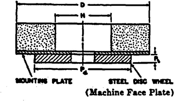
 nor shall the difference between D and P4 exceed 2 inches. It is recommended that P4 equal D wherever practical.