
In order to promote public education and public safety, equal justice for all, a better informed citizenry, the rule of law, world trade and world peace, this legal document is hereby made available on a noncommercial basis, as it is the right of all humans to know and speak the laws that govern them.
SUPERSEDED
USA STANDARD
Best Copy Available Comes Off Film
“SUPERSEDED BY LATER ISSUE”
USAS B56.1 - 1969
Sponsor
The American Society of Mechanical Engineers
Published by
THE AMERICAN SOCIETY OF MECHANICAL ENGINEERS
United Engineering Center 345 East 47th Street New York, N. Y. 10017
620
Ac03a.m
USA STANDARED
This USA Standard is one of nearly 3000 standards approved as American Standards by the American Standards. Association. On August 24, 1966, the ASA was reconstituted as the United States of America Standards Institute. Standards approved as American Standards are now designated USA Standards. There is no change in their index indentification or technical content.
Any part of this standard may be quoted. Credit lines should read; ‘Extracted from USA Standard Safety Standard for Powered Industrial Trucks (USAS B56.1-1969) with the permission of the publisher, The American Society of Mechanical Engineers, United Engineering Center, 345 East 47th Street, New York, New York 10017.’
copyright, © 1969 by
THE AMERICAN SOCIETY OF MECHANICAL ENGINEERS
Printed in U.S.A.
iiIN June, 1946, The American Society of Mechanical Engineers adopted a resolution to develop a safety code on powered industrial trucks. On August 7, 1947, the American Standards Association approved ASME’s sponsorship of this standard. The organizational meeting was held on May 20, 1948.
Comments from the first draft, dated April, 1949, were incorporated in a final draft, dated November, 1949, which was submitted to sectional committee members for letter ballot vote and was unanimously affirmed. In June, 1950, ASA approved the standard as submitted.
In accordance with ASA procedure to review publications every five years, the first revision was completed on March 8, 1955, and the second revision on August 18, 1959. The third revision was started under the review procedure of ASA. It was completed under the newly constituted (September 1, 1966) United States of America Standards Institute on September 10, 1969.
iii ivUSA Standards Committee B56,
Safety Standard for Powered Industrial Trucks
Officers
C. H. Powers, Chairman John Bayuk, Secretary
USA Standards Committee
AMERICAN INSURANCE ASSOCIATION
H. J. Eiermann, Royal-Globe Insurance Group, New York, New York
J. N. Schindler, Alternate, Royal-Globe Insurance Group, New York, New York
AMERICAN MUTUAL INSURANCE ALLIANCE
F. H. Deeg, American Mutual Alliance, Chicago, IIIinois
AMERICAN SOCIETY OF MECHANICAL ENGINEERS, THE
W. W. Olsen, Eaton Yale & Towne, Inc., Philadelphia, Pennsylvania
C. H. Powers, Clark Equipment Company, Battle Creek, Michigan
M. J. Rowan, Modern Marerials Handling, Boston, Massachusetts
L. J. Wenstrup, Jr., Alternate, Eaton Yale & Towne, Inc., Batavia, New York
AMERICAN SOCIETY OF SAFETY ENGINEERS
Representative To Be Appointed
AMERICAN TRUCKING ASSOCIATION, INC.
Edward Minick, Spector Freight System, Inc., Secaucus, New Jersey
D. G. McDougall, Alternate, The Operations Council of the American Trucking Association, Inc., Washington, D.C.
AMERICAN WAREHOUSEMEN’S ASSOCIATION
A. M. Lownsbury, Central Detroir Warehouse Company, Detroit, Michigan
ASSOCIATED GENERAL CONTRACTORS OF AMERICA, INC., THE
A. L. Schmuhl, The Associated General Contractors of America, Inc., Washington, D. C.
ASSOCIATION OF AMERICAN RAILROADS
J. T. Andrew, Great Northern Railway Company, St. Paul, Minnesata
R. E. Mann, New York Central System, New York, New York
AUTOMOBILE MANUFACTURERS ASSOCIATION
K. S. Hedges, General Motors Corporation, Detroit, Michigan
CAN MANUFACTURERS INSTITUTE, INC.
William Atkinson, Jr., Contineral Can Company, New York, New York
DEPARTMENT OF LABOR-STATE OF CONNECTICUT
Edmund Mellale, State of Connecticut, Labor Department, Hartford, Connecticut
DEPARTMENT OF LABOR AND INDUSTRIES-STATE OF WASHINGTON
R. W. Minick, Department of Labor & Industries, Division of Safety, Olympia, Washington
W. H. Hahne, Alternate, Department of Labor & Industries, Division of Safety, Olympia, Washington
DEPARTMENT OF LABOR-STATE OF RHODE ISLAND
F. W. Marcaccio, Department of Labor, Providence, Rhode Island
EASTMAN KODAK COMPANY
E. V. Clancey, Eastman Kodak Company, Rochester, New York
GENERAL SERVICES ADMINISTRATION
Ward Collings, General Services Administration, Washington, D.C.
INDUSTRIAL SAFETY EQUIPMENT ASSOCIATION, INC.
C. N. Sumwalt, Jr., Industrial Safety Equipment Association, Inc., New York, New York
INDUSTRIAL TRUCK ASSOCIATION
J. A. Draxler, The Elwell-Parker Electric Company, Cleveland, Ohio
J. D. Schell, Clark Equipment Company, Battle Creek, Michigan
C. D. Gibson, Alternate, The Raymond Corporation, Greene, New York
E. R. Sirotak, Alternate, Towmotor Corporation, Cleveland, Ohio
INTERNATIONAL ASSOCIATION OF GOVERNMENTAL LABOR OFFICIALS
G. A. Sherman, Division of Industrial Safety, Department of Industrial Relations, San Francisco, California
E. A. Brubaker, Alternate, Division of Industrial Safety, Department of Industrial Relations, San Francisco, California
INTERNATIONAL MATERIAL MANAGEMENT SOCIETY
Leonard Churches, Ford Motor Company, Dearborn, Michigan
G. V. Schultz, Alternate, McGraw-Hill, Inc., New York, New York
MARITIME ASSOCIATION OF THE PORT OF NEW YORK, THE
F. X. McQuade, John W. McGrath Corporation, New York, New York
MATERIAL HANDLING INSTITUTE, INC., THE
C. D. Gibson, The Raymond Corporation, Greene, New York
E. R. Sirotak, Towmotor Corporation, Cleveland, Ohio
O. S. Carliss, Alternate, Eaton Yale & Towne, Inc., Philadelphia, Pennsylvania
J. D. Schell, Alternate, Clark Equipment Company, Battle Creek, Michigan
NATIONAL ELECTRICAL MANUFACTURERS ASSOCIATION
J. E. Knarr, Baker Division, Otis Elevator Company, Cleveland, Ohio
L. M. Maresh, Square D Company, Milwaukee, Wisconsin
W. A. Samsonoff, Alternate, National Electrical Manufacturers Association, New York, New York
R. A. Schmitz, Alternate, Baker Division, Otis Elevator Company, Cleveland, Ohio
NATIONAL FIRE PROTECTION ASSOCIATION
C. B. Patterson, E. I. du Pont de Nemours & Company, Inc., Wilmington, Delaware
NATIONAL LP-GAS ASSOCIATION
W. H. Johnson, National LP-Gas Association, Chicago, Illinois
NATIONAL SAFETY COUNCIL
J. V. Skendall, Harbison-Walker Refractories Company, Pittsburgh, Pennsylvania
L. Dutton, Alternate, National Safety Council, Chicago, Illinois
NATIONAL SAFETY COUNCIL (CHEMICAL SECTION)
C. M. Olson, Hooker Chemical Corporation, Niagara Falls, New York
NEW YORK SHIPPING ASSOCIATION, INC.
Capt. G. D. Barlow, New York Shipping Association, Inc., New York, New York
NEW YORK STATE DEPARTMENT OF LABOR
A. E. Perina, State Labor Department, New York, New York
Samuel Greenwald, Alternate, State Labor Department, New York, New York
SILENT HOIST & CRANE COMPANY, INC.
R. E. Cohen, Silent Hoist & Crane Company, Inc., Brooklyn, New York
SOCIETY OF AUTOMOTIVE ENGINEERS, INC.
J. C. Crawford, Society of Automotive Engineers, Inc., New York, New York
SOCIETY OF PACKAGING & HANDLING ENGINEERS
F. H. Wiley, International Harvester Company, Chicago, Illinois
THE TELEPHONE GROUP (REPRESENTING THE TELEPHONE INDUSTRY IN USASI ACTIVITIES)
G. A. Piley, Western Electric Company, Inc., Chicago, Illinois
UNDERWRITERS' LABORATORIES, INC.
E. W. Killoren, Underwriters' Laboratories, Inc., Chicago, Illinois
E. J. Huber, Alternate, Underwriters' Laboratories, Inc., Melville, New York
U.S. DEPARTMENT OF LABOR
P. F. Cestrone, Bureau of Labor Standards, U.S. Department of Labor, Washington, D.C.
J. A. Proctor, Alternate, Bureau of Labor Standards, U.S. Department of Labor, Washington, D.C.
UNITED STEEL WORKERS OF AMERICA
Frank Burke, United Steel Workers of America, Pittsburgh, Pennsylvania
INDIVIDUAL MEMBERS
John Bayuk, Lycoming Division of Avco Corporation, Stratford, Connecticut
C. S. Bruce, Traffic Accident Analyst, Fort Myers, Florida
R. J. Sweeney, Drake, Sheahan, Sweeney and Hupp, New York, New York
LIASON MEMBERS
CANADIAN STANDARDS ASSOCIATION
Charles Bryan, Henry J. Kaiser Company (Canada) Limited, Montreal, Quebec, Canada
L. J. Scock, Canada Steamship Lines Limited, Montreal, Quebec, Canada
| PAGE | |||
|---|---|---|---|
| PART I – GENERAL | |||
| Introduction | 1 | ||
| SECTION 1 – Scope | 1 | ||
| SECTION 2 – Purpose and Effective Date | 1 | ||
| SECTION 3 – Interpretation | 1 | ||
| PART II – FOR THE MANUFACTURER | |||
| SECTION 4 – Design & Construction Standards | 2 | ||
| 401 Introduction | 2 | ||
| 402 Capacity | 2 | ||
| 403 Rated Capacity or Capacity Rating | 2 | ||
| 404 Alternate Rated Capacity | 2 | ||
| 405 Nameplates and Markings | 2 | ||
| 406 Stability – Tilting Platform Tests | 3 | ||
| 407 Steering Arrangements | 31 | ||
| 408 Steering – Rider Trucks | 32 | ||
| 409 Steering Handle – Motorized Hand, and Hand/Rider Trucks | 32 | ||
| 410 Braking Performance All Powered Industrial Trucks Except Industrial Tractors | 32 | ||
| 411 Safety Control and Brakes, Electric Trucks, Sit-Down Rider | 33 | ||
| 412 Safety Control and Brakes, Electric Trucks, Stand-Up Rider | 35 | ||
| 413 Safety Control and Brakes, International Combustion Powered Industrial Trucks, Sit-Down Rider | 35 | ||
| 414 Safety Control and Barkes, International Combustion Powered Industrial Trucks, Stand-Up Rider | 35 | ||
| 415 Safety Control and Brakes, Electric Hand, and Hand/Rider Trucks | 36 vii | ||
| 416 Safety Control and Brakes, Order Picker Trucks, High Lift | 36 | ||
| 417 Load Handling Controls | 36 | ||
| 418 TiH Mechanism | 37 | ||
| 419 Forks | 37 | ||
| 420 Fork Extensions | 37 | ||
| 421 Overhead Guard | 37 | ||
| 422 Load Backrest Extension | 39 | ||
| 423 Pedal and Platform Surfaces | 39 | ||
| 424 Operator Platforms | 39 | ||
| 425 Overtravel Limits | 39 | ||
| 426 Wheel Guards | 39 | ||
| 427 Warning Device | 39 | ||
| 428 Guards for Moving Chains, Cables, Etc | 39 | ||
| PART III – FOR THE USER | |||
| SECTION 5 – General Safety Practices | 40 | ||
| 501 Introduction | 40 | ||
| 502 Stability | 40 | ||
| 503 Modifications, Nameplates, Markings, and Capacity | 40 | ||
| 504 Safety Guards | 40 | ||
| 505 Fuel Handling and Storage | 41 | ||
| 506 Changing and Charging Storage Batteries | 41 | ||
| 507 Hazardous Atmospheres | 41 | ||
| 508 Aisles and Obstructions | 42 | ||
| 509 Paint Color | 42 | ||
| 510 Lighting for Operating Areas | 42 | ||
| 511 Control of Noxious Gases and Fumes | 42 | ||
| 512 Dockboards | 42 | ||
| 513 Trucks and Railroad Cars | 43 | ||
| 514 Warning Device | 43 | ||
| SECTION 6–Operating Safety Rules and Practices | 43 | ||
| 601 Operator Qualifications | 43 | ||
| 602 Operator Training | 43 | ||
| 603 General | 43 | ||
| 604 Traveling | 44 | ||
| 605 Loading | 44 | ||
| 606 Operator Care of the Truck | 45 | ||
| SECTION 7–Maintenance | 45 | ||
| APPENDIX A – Glossary of Commonly Used Words and Phrases | 47 | ||
| APPENDIX B – Other Codes and Standards | 53 | ||
USA STANDARD
Safety Standard
for
Powered Industrial Trucks
This standard is one of a series that has been formulated under the administrative sponsorship of The American Society of Mechanical Engineers in accordance with the standards committee method and the procedures of the United States of America Standards Institute.
Pursuant to the requirements of USASI, the membership of the standards committee dealing with this Safety Standard includes representatives of:
In addition, not more than one third of the membership of this committee is from any one category. This standard has been formulated by a consensus of the members of this committee.
Safety requirements relating to the elements of design, operation and maintenance of powered industrial trucks – not including vehicles intended primarily for earth moving or over the road hauling.
The purpose of this standard is to promote safety in the design, construction, application, operation, and maintenance of powered industrial trucks. This standard may be used as a guide by governmental authorities desiring to formulate safety rules and regulations. This standard is also intended for voluntary use by others associated with manufacturing or utilizing powered industrial trucks.
Questions on the interpretation of this standard should be addressed in writing to – The American Society of Mechanical Engineers, United Engineering Center, 345 East 47th Street, New York, New York 10017 – for referral to the Standards Committee.
This standard shall become effective one year after publication and is intended to have prospective application only.
To carry out the provision of this Standard, the word “shall” is to be understood as mandatory and the work “should” as advisory.
The word “approved” means acceptable to the inspection authority having jurisdiction.
A glossary of commonly used words and phrases with the meanings normally accorded them in the industry is attached as Appendix A.
1This part sets forth Safety Standards for the Design and Construction of powered industrial trucks.
Rated capacity for trucks up to and including 20,000 pounds shall be based on the strength of the various components in the truck and for trucks covered in 403C, also on 406 of this Standard, and shall be expressed as follows:
If any of the foregoing trucks is equipped with attachments, the rated capacity shall be expressed in pounds at a specified load center and for a specified load elevation.
The maximum weight, expressed in pounds, of a load with a stated horizontal and vertical distance to the center of gravity of the load that a given truck, based on the strength of the various components of the truck and, when applicable also on 406 of this Standard, can transport and stack to a height established by the manufacturer.
E583— A battery assembled as a unit with a cover for use in Type E trucks which do not have a covered battery compartment.
EE583 — A battery assembled as a unit with a cover that can be locked for use in Type EE trucks which do not have an enclosed battery compartment.
EO583 — A battery assembled as a unit without a cover for use in a Type E truck having a covered battery compartment or in a Type EE truck having an enclosed battery compartment with locking means.
EX583 — A battery assembled as a unit with a cover that can be locked. For use in EX trucks which do not have a locked battery compartment.
For batteries installed in electric trucks, battery weight shall be stamped on the battery tray near the lifting means as follows: “Service Weight lbs”
Serial Number
Weight of Attachment
Capacity or Rated Capacity of Attachment
The following instruction (or equivalent): “Capacity of Truck and Attachment combination may be less than capacity shown on attachment — consult truck nameplate.”
Stability determinations may be made by one of the following methods:
| Test No. | Tests For: | Platform Slope in Relation to Truck | Fork Height | Loaded or Unloaded | Load Center | Mast or Fork Tilt | Platform Slope Values |
|---|---|---|---|---|---|---|---|
| 1 | Forward Stacking | Forward | At max. elevation | Loaded | 24" | As specified–see text | 4%*3.5%** |
| 2 | Forward Travel | Forward | 12" | Loaded | 24" | Full Rearward | 18% |
| 3 | Lateral Stacking | Lateral | At max. elevation | Loaded | 24" | Full Reatward | 6% |
| 4 | Lateral Travel | Lateral | 12" | Unloaded | Full Rearward | Graph A | |
| *Up to and including 10,000 lb at 24" Lead Center. **Over 10,000 lb up to and including 20,000 lb at 24" Lead Center. |
|||||||
The following tests are designed to verify rated capacities of counterbalanced trucks having rated capacities up to and including 20,000 lb at 24 inches load center and to determine capacity or alternate rated capacity. If these tests are used to determine capacity or alternate rated capacities, use appropriate loads and load centers instead of those herein specified. If other tests of tests for trucks over 20,000 lb rated capacity are required, the details should be agreed upon between the interested parties.
Using the procedure outlined for the test, a truck carrying the rated capacity load at maximum elevation shall not overturn when the platform upon which the truck is standing is titled to the slope indicated in the following table about an axis parallel to the axis of the load wheels and in a direction to increase the load overhang.
| Rated Capacity | Slope |
|---|---|
| Up to and including 10,000 lb at 21"Load Center | [Illegible Text Omitted on Page 4] |
| Over 10,000 lb up to and including 20,000 lb at 24"Load Center | [Illegible Text Omitted on Page 4] |
Procedure for Longitudinal Stability (Stacking) Tilting Platform Test
Using the procedure outlined for the test, a truck carrying rated capacity load at full rearward tilt of the mast and with the load elevated 12 inches from the floor, measured at the point of intersection of the load carrying surfaces of the forks, shall not overturn when the platform upon which the truck is standing is tilted to an 18 percent slope about an axis parallel to the axis of the load wheels and in a direction to increase the load overhang.
Procedure for Longitudinal Stability (Traveling) Tilting Platform Test
It may also be necessary to restrain the load wheels by external means between the wheels and truck, and/ or to apply service brakes by external means to hold the truck in place during this test.
Using the procedure outlined for the test, a truck carrying the rated capacity load at maximum elevation and at maximum rearward tilt permitted by the truck mechanism, at that elevation, shall not overturn when the platform upon which the truck when the platform upon which the truck is standing is tilted to a 6 percent slope about an axis parallel to a line connecting the center or either load wheel tire (or outermost tire where multiple tires are used) and the projection perpendicular to the platform of the point of intersection of the longitudinal centerline of the truck and centerline of the steering wheels. The steering wheel nearest the tilting axis shall be positioned parallel to the tilting axis of the platform.
Procedure for Lateral Stability (Stacking) Tilting Platform Test
1If necessary, it is permissible to cover the surface of the tilting platform with a friction increasing material such as liquid paint or adhesive applied tape containing friction material.
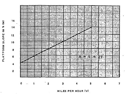
5Using the procedure outlined for the test, an empty truck at full rearward tilt of the mast and with the forks elevated 12 inches from the floor, measured at the point of intersection of the load carrying surfaces of the forks, shall not overturn when the platform upon which the truck is standing is tilted to the slope specified in the Graph A, about an axis parallel to a line connecting the center of either load-wheel tire (or outermost tire where multiple tires are used) and the projection perpendicular to the platform of the point of intersection of the longitudinal
GRAPH A LATERAL STABILITY-TRAVELING
6centerline of the truck and the centerline of the steering wheels. The steering wheel nearest the tilting axis shall be positioned parallel to the tilting axis of the platform. Values are based on ultimate overturn, not on point where one drive tire leaves the ground.
Procedure for Lateral Stability (Traveling) Tilting Platform Test
2It will probably be necessary to cover the surface of the tilting platform with a friction-increasing material such as liquid paint, adhesive applied tape containing friction material, or safety tread with perforated buttons. It may also be necessary to apply service brakes by external means to hold the truck in place during the test.

LATERAL STABILITY TILTING PLATFORM TRUCK POSITION
7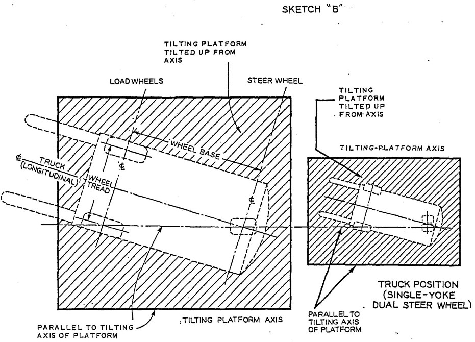
LATERAL STABILITY TILTING PLATFORM TRUCK POSITION
8These requirements apply to self-loading narrow-aisle rider trucks normally equipped with forks, such as reach or straddle trucks.
| Test No. | Test For: | Platform Slope in Relation to Truck | Fork Height | Loaded or Unloaded | Load Center | Reach Extended or Retracted (if reach type) | Mast or Fork Tilt | Platform Slope Values |
|---|---|---|---|---|---|---|---|---|
| N1 | Forward Stacking | Forward | (Note 1) | Loaded | 24" | Extended | As Specified See Text | 4% |
| N2* | Forward Traveling | Forward | (Note 2) | Loaded | 24" | Retracted | Full Rearward | 18% |
| N3 | Lateral Stacking |
Lateral | (Note 1) | Loaded | 16" or 24" (whichever is less stable) | Retracted | *** | 6% |
| N3A | Lateral Stacking |
Lateral | (Note 1) | Unloaded | – | Retracted | *** | 8% |
| N4 | Lateral Traveling | Lateral | (Note 2) | Unloaded | – | Retracted | *** | Graph A |
| N5** | Rearward Stacking | Rearward | (Note 1) | Loaded | 16" | Retracted | *** | 14% |
| N5A | Rearward Stacking | Rearward | (Note 1) | Unloaded | – | Retracted | *** | 14% or 18%**** |
| N6 | Rearward Traveling | Rearward | (Note 2) | Unloaded | – | Retracted | *** | Graph B |
| Note 1: At maximum elevation. Note 2: 6 In, above outrigger and/or load wheels. |
||||||||
| *Test N2 – especially with straddle trucks – stability is usually obvious, in which case test may be waived. | ||||||||
| **Test N5 – both reach and straddle trucks (except with tilting mast) – stability is usually obvious, in which case test may be waived. | ||||||||
| ***For trucks with tilting masts the mast shall be vertical or at full rearward tilt, whichever is less stable. For trucks with tilting forks, the forks shall be horizontal or at full upward tilt, whichever is less stable. | ||||||||
| ****Platform slope value of 14 percent applies to trucks with single rear wheel drive (or brake), and 18 percent applies to trucks with dual rear wheel drive (or brakes), respectively. | ||||||||
These tests roughly correspond to tests of the same numbers for Counterbalanced Trucks. The letter “N” has been added to clearly distinguish Narrow Aisle truck tests from Counterbalanced truck tests. Narrow-Aisle-Type Trucks require several tests in addition to those for Counterbalanced trucks.
For some truck configurations, stability may obviously be — far in excess of the minimum slope values as required by some of the tests. In such cases, those tests may be omitted. Examples: Tests #N2 and #N5, except for unusual truck proportions.
Trucks may be of the reaching or non-reaching type, equipped with tilting mast, or forks that tilt alone without tilting mast, or without any form of mast or fork tilt.
To simulate an operator, a 200 1b weight
9shall be located with the center of gravity centered 10 inches above the compressed operator's seat for sit-down trucks and centered 40 inches above the operator's platform for stand-up trucks. This weight shall be used only when it will worsen the stability condition being tested and omitted when it would help.
Chocks may be used as needed to maintain the truck position of the platform. The use of chocks approximately 10 percent of the diameter of the wheel, but not less than 1 inch nor more than 2 inches high is allowed when necessary.
The critical—balance point of the truck in any test will be that platform slope which if increased further would produce complete overturning of the truck. Effects of frame or structural members in contact with platform are recognized as beneficial and should be included in determining a “critical-balance” slope.
The following tests are designed to verify rated capacities of Narrow-Aisle-Rider fork trucks having rated capacities up to and including 10,000 lb at 24-inch load center and to determine capacity or alternate rated capacities. If these tests are used to determine capacity or alternate rated capacities, use appropriate loads and load centers instead of those herein specified. If other tests or tests for trucks over 10,000 lb rated capacity are required, the details should be agreed upon between the interested parries.
Using the procedure outlined for the test, a truck carrying the rated capacity load at maximum elevation shall not overturn when the platform upon which the truck is standing is tilted to a slope of 4 percent about an axis parallel to the axis of the load wheels, and in a direction to increase the load overhang.
Procedure for Forward Stability (Stacking) Tilting Platform Test #N1
Using the procedure outlined for the test, a truck carrying rated capacity load at full rearward tilt of the mast and/or upward tilt of forks, and with the load elevated 6 inches above top of the outrigger and/or load wheels, measured at the point of intersection of the two load engaging surfaces of the forks, shall not overturn when the platform upon which the truck is standing is tilted to an 18 percent slope about an axis parallel to the axis of the load wheels and in a direction to increase the load overhang.
10Procedure for Forward Stability (Traveling) Tilting Platform Test #2
Using the procedure outlined for these tests, a truck shall not overturn when the platform upon which the truck is standing is tilted to a 6 percent slope for loaded truck (Test #N3), or an 8 percent slope for unloaded truck (Test #N3A).
Slope values are based on ultimate overturn, not on point where one or more wheels leave the platform.
Procedure for Lateral Stability (Stacking, Loaded) Tilting Platform Test #N3
3 Tests #N3 and #N3A are identical except that in Test #N3 the truck is loaded and in Test #N3A the truck is unloaded.
Although trucks are rated at 24 inches load center, the load center for Test #N3 should be either 24 or 16 inches – whichever would produce the less stable condition. This decreased load center is specified, recognizing that loads may be handled which have a higher density and therefore, shorter load center than the truck rating. Decreasing load center distance is usually in the direction of decreasing lateral stability, hence should be recognized in Test #N3.
4 It will usually be found that this axis runs through one of the following: a) one of the rear wheels, or b) a pivot point of support for trucks having a laterally articulating rear wheel mounting.
11 position is determined to be less stable, the truck shall be tested at maximum elevation for each tilt restriction permitted by the truck mechanism. For trucks with tilting forks, the forks shall be horizontal or at full upward tilt, whichever is less stable.Procedure for Lateral-Stability (Stacking, Unloaded) Tilting-Platform Test #3A
Using the procedure outlined for the test, an empty truck with the forks elevated 6 inches above top of the outriggers and/or load wheels, measured at the point of intersection of the two load engaging surfaces of the forks, shall not overturn when the platform upon which the truck is standing is tilted to the slope specified in Graph A.
Slope values are based on ultimate overturn, not on point where one or more wheels leave the platform.
Procedure for Lateral-Stability (Traveling) Tilting-Platform Test #N4
5 It will usually be found that this axis runs through one of the following: a) one of the rear wheels, or b) a pivot point of support for trucks having a laterally articulating rear-wheel mounting.
12 the underside of the attachment or carriage – whichever is lower.Using the procedure outlined for these tests, a truck shall not overturn when the platform upon which the truck is standing is tilted to a 14 per cent slope for loaded truck (Test #N5), and a 14 percent or 18 percent slope for unloaded truck (Test #N5A), depending on whether the truck has single rear-wheel drive (or brake) or dual rear-wheel drive (or brakes), respectively.
Slope values are based on ultimate overturn, not on point where one or more wheels leave the platform.
Procedure for Rearward-Stability (Stacking, Loaded) Tilting-Platform Test #N5
Procedure for Rearward-Stability (Stacking, Unloaded) Tilting-Platform Test #N5A
Using the procedure outlined for the test, and empty truck with the forks
6 Tests #N5 and #N5A are identical except that in Test #N5 the truck is loaded and in Test #N5A the truck is unloaded.
Although trucks are rated at 24-in. load center, a load center distance of 16 inches should be used for Test #N5. This decreased load center is specified, recognizing that loads may be handled which have a higher density and, therefore, shorter load center than the truck rating. Decreasing load center distance is in the direction of decreasing rearward stability, hence should be recognized in Test #N5.
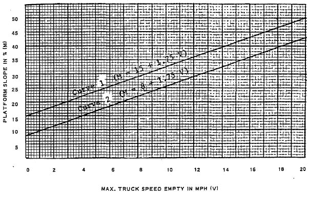
13elevated 6 inches above top of the outriggers and/or load wheels, measured at the point of intersection of the two load engaging surfaces of the forks, shall not overturn when the platform upon which the truck is standing is tilted to the slope specified in Graph B.
Slope values are based on ultimate overturn, not on point where one or more wheels leave the platform.
Procedure for Rearward Stability (Traveling) Tilting Platform Test #N6
GRAPH B
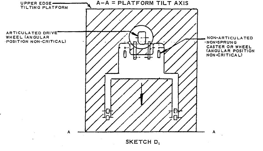
14TILTING PLATFORM TESTS
NARROW AISLE TYPE – TRUCKS
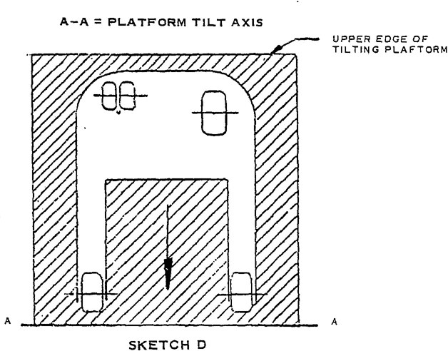
POSITIONING FOR FORWARD TESTS #Nl & #N2
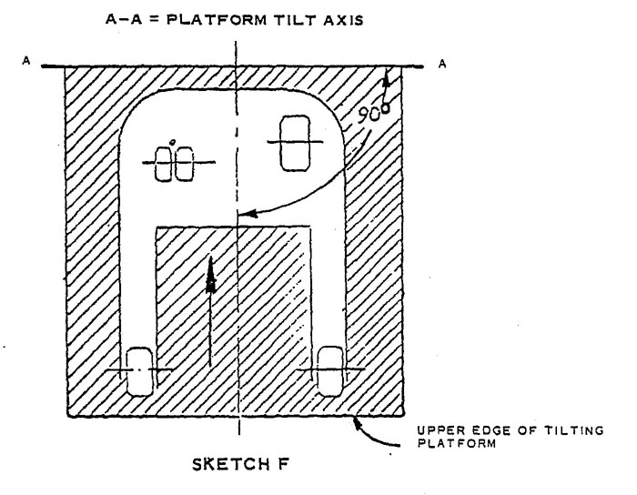
POSITIONING FOR REARWARD TESTS #N5, #N5A, & #N6
15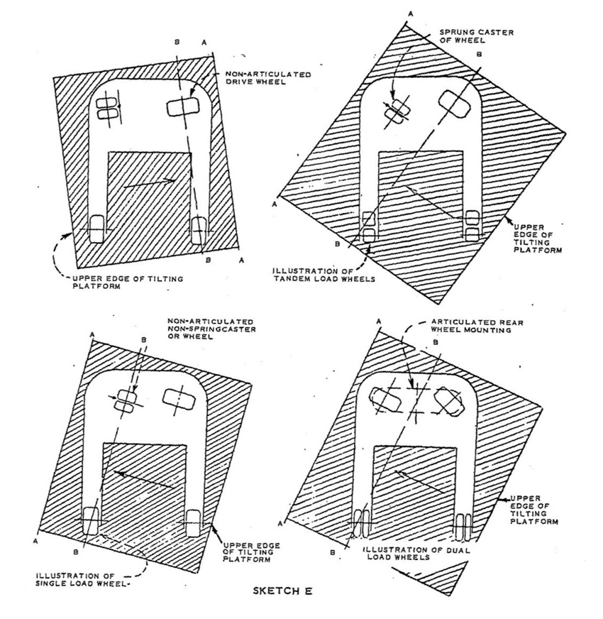
A–A = Paltform Tilt Axis
B–B = Truck Axis of Original Tilt
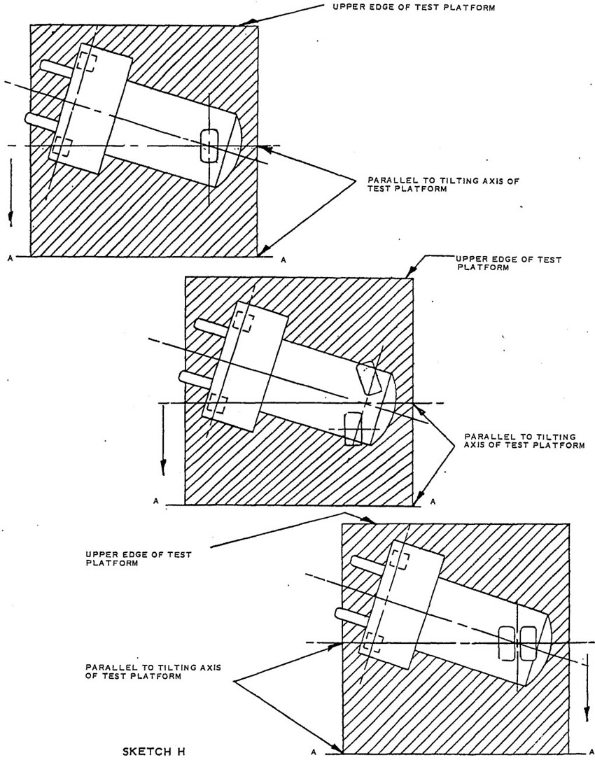
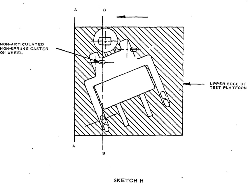
TILTING PLATFORM TESTS
NON-COUNTERBALANCED, ARTICULATED DRIVE TRUCKS
POSITIONING FOR FORWARD TESTS #N1 & #N2
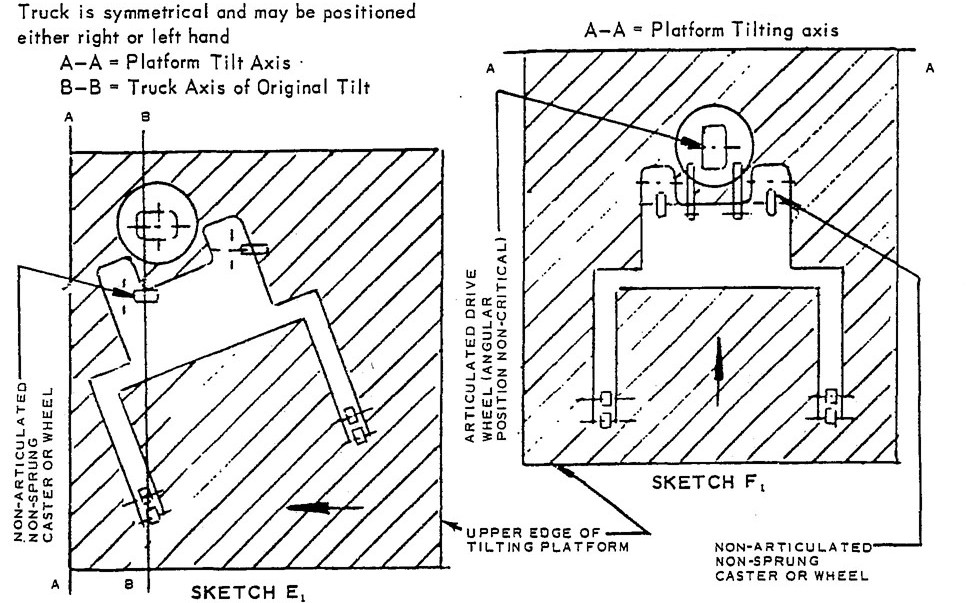
POSITIONING FOR LATERAL TESTS #N3,#N3A &#N4
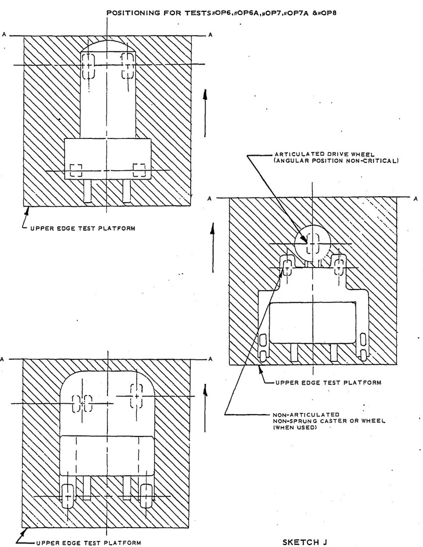
POSITIONING FOR REARWARD TESTS #N5,#N5A &#N6
For some trucks the results of the test(s) may be obvious. In these cases the test(s) may be waived.
| Test No. | Tests For | Platform Slope in Relation To Truck | Fork Height | Loaded or Unloaded | Load Center | Mast or Fork Tilt | Platform Slope Values |
|---|---|---|---|---|---|---|---|
| OP1 | Long Stack |
Sketch “G” |
Max. for limit of travel speed | Loaded | 24" | None | Graph C |
| OP2 | Long Travel |
Sketch “G” |
12" | Loaded | 24" | Full Rearward | 18% |
| OP3 | Lateral Stack |
Sketch “H” |
Max./Travel | Loaded | 16" or 24" (whichever is less stable) |
** | 6% |
| OP4 | Lateral Stack |
Sketch “H” |
Maximum | Unloaded | ** | 8% | |
| OP4A | Lateral Travel |
Sketch “H” |
Max./Travel | Unloaded | ** | Graph D*** (Curves 1 & 2) |
|
| OP5 | Lateral Travel |
Sketch “H” |
12" | Unloaded | ** | Graph D (Curve 1) |
|
| OP6 | Long Stack |
Sketch “J” |
Max./Travel | Loaded | 16" | ** | Graph D (Curve 1) |
| OP6A | Long Stack |
Sketch “J” |
Maximum | Loaded | 16" | ** | 14% |
| OP7 | Long Stack |
Sketch “J” |
Max./Travel | Unloaded | ** | Graph D (Curve 1) |
|
| OP7A | Long Stack |
Sketch “J” |
Maximum | Unloaded | ** | 14 – 18%* | |
| OP8 | Long Travel |
Sketch “J” |
12" | Unloaded | ** | Graph E | |
| * Platform slope value of 14 percent applies to trucks with single rear wheel drive (or brake) and 18 percent applies to trucks with dual rear wheel drive (or brakes) respectively. | |||||||
| ** For trucks with tilting masts, the mast should be vertical or at full rearward till, whichever is less stable. For trucks with tilting forks, the forks should be horizontal or at full upward till, whichever is less stable. | |||||||
| *** Curves 1 and 2 refer to travel with unrestricted turning and to straight forward and reverse travel, no turning. Under the conditions specified for positioning in the test procedure, ±10 degrees from straight forward and reverse is considered as no turning. | |||||||
The following tests represent minimum stability requirements for order picker trucks with traction control on the lifting device, and not restrained by external means, having rated capacities up to and including 10,000 pounds at a 24 inch load center.
To simulate an operator, a 200 pound weight should be located with the center of gravity centered 40 inches above the operator’s platform. This weight should be used only when it will worsen the stability condition being tested and omitted when it would help.
It may be necessary to cover the surface of the tilting platform with a friction increasing material such as paint containing friction material, adhesive tape coated with friction material, or metallic “safety tread” with perforated buttons.
It may also be necessary to restrain the load wheels by external means between the wheels and truck, and/or to apply brake(s) by external means to hold the truck in place during testing. The use of chocks approximately 10 percent of the diameter of the wheel, but not less than 1 inch nor more than 2 inches high is allowed when necessary.
The critical-balance point of the truck in any test will be that test platform slope which if increased further would produce complete overturning of the truck. Effects of frame or structural members contact with the test platform are recognized as beneficial and should be included in determining a “critical-balance” slope.
When attachments are supplied as original equipment, the same stability tests should apply, except the plumb line (for Test #OP1) should be attached to, and the 12 inch measurement (for Tests #OP2, #OP5, and #OP8) should be made to the underside of the carriage, attachment, or load – whichever is lower. The truck should be equipped with the attachment and the test load (when required) should be representative of the capacity of the truck and attachment combination.
If these tests are used to determine capacity or alternate rated capacities, use appropriate loads and load centers instead of those herein specified. If other tests or tests for trucks over 10,000 pounds rated capacity are required, the details should be agreed upon between the interested parties.
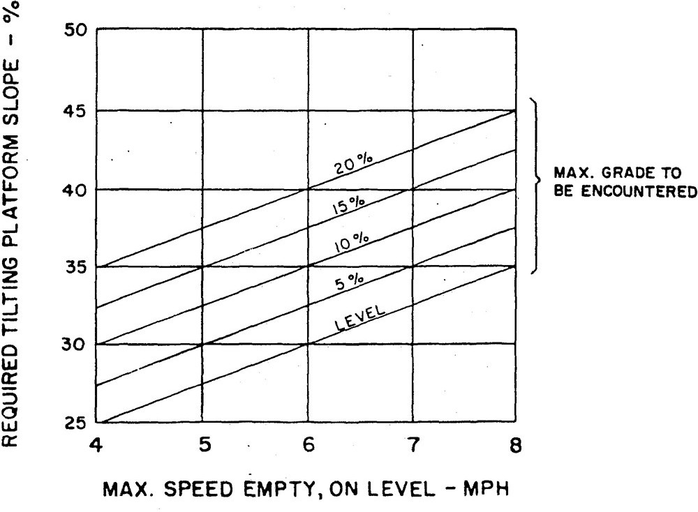
Using the procedure outlined for the test, a truck carrying the rated capacity load elevated to the maximum height for the limit of travel speed, should not overturn when the test platform upon which the truck is standing is tilted to the slope specified by Graph C about an axis parallel to the axis of the load wheels and in a direction to increase the load overhang.
Procedure for Longitudinal Stability (Stacking) Tilting Platform Test
Using the procedure outlined for the test, a truck carrying rated capacity load, and with the load elevated 12 inches from the test platform, measured at the point of intersection of the load carrying surfaces of the forks, should not overturn when the test platform upon which the truck is standing is tilted to an 18 percent slope about an axis parallel to the axis of the load wheels, and in a direction to increase the load overhang.
Procedure for Longitudinal Stability (Traveling) Tilting-Platform Test
Using the procedure outlined for the test, a truck carrying the rated capacity load elevated to the maximum height at which unrestricted horizontal travel is permitted, should not overturn when the test platform upon which the truck is standing is tilted to a 6 percent slope.
Slope values are based on ultimate overturn, not on point where one or more wheels leave the platform.
Procedure for Lateral Stability (Stacking) Titling Platform Test
Using the procedure outlined for the test, an empty truck with the forks elevated to the maximum height should not overturn when the test platform upon
7 It will usually be found that this axis runs through one of the following; (a) one of the rear wheels or (b) a pivot point of support for trucks having a laterally articulating rear wheel mounting.
20which the truck is standing is tilted to an 8 percent slope.
Slope values are based on ultimate overturn, not on point where one or more wheels leave the platform.
Procedure for Lateral Stability (Stacking) Tilting Platform Test
Using the procedure outlined for the test, an empty truck with the forks elevated to any height up to the maximum height at which horizontal travel is permitted, and for the travel speed allowable at that height, should not overturn when the test platform, and for the travel speed allowable at that height, should not overturn when the test platform upon which the truck is standing is tilted to the slope specified by Graph D, Curve 1, for unrestricted turning and by Graph D, Curve 2, for straight forward and reverse travel, travel, no turning ± 10 degrees.
Slope values are based on ultimate overturn, not on point where one or more wheels leave the platform.
Procedure for Lateral Stability (Traveling) Tilting Platform Test
Using the procedure outlined for the test, an empty truck with the forks elevated 12 inches from the test platform measured at the point of intersection of the load carrying surfaces of the forks, should not overturn when the test platform upon which the truck is standing is tilted to the slope specified in Graph D, Curve 1.
Slope values are based on ultimate overturn, not on point where one or more wheels leave the platform
Procedure for Lateral Stability (Traveling) Tilting Platform Test
5It will usually be found that this axis runs through one of the following: (a) one of the rear wheels or (b) a pivot point of support for trucks having a laterally articulating rear wheel mounting.
21Using the procedure outlined for this test, a truck carrying the rated capacity load elevated to the maximum height at which horizontal travel with unrestricted turning is permitted, should not overturn when the test platform upon which the truck is standing is tilted to the slope specified in Graph D. Curve 1.
Procedure for Stability (Stacking, Loaded) Tilting Platform Test
Using the procedure outlined for this test the truck carrying rated capacity load elevated to the maximum height should not overturn when the test platform upon which the truck is standing is tilted to a 14 percent slope.
Procedure for Stability (Stacking, Loaded) Tilting Platform Test
Using the procedure outlined for the test, an empty truck with the forks elevated to the maximum height at which horizontal travel is permitted and for the travel speed allowable at that height, should not overturn when the test platform upon which the truck is standing is tilted to the slope specified in Graph D, Curve 1.
22Procedure for Stability (Stacking, Unloaded) Tilting Platform Test
Using the procedure outlined for this test an empty truck with the forks elevated to the maximum height should not overturn when the test platform upon which the truck is standing is tilted to a 14 percent or 18 percent slope depending on whether the truck has single, rear-wheel drive (or brake) or dual wheel drive (or brakes), respectively.
Procedure for Stability (Stacking, Unloaded) Tilting Platform Test
Using the procedure outlined for the test, an empty truck with the forks elevated 12 inches from the test platform, measured at the point of intersection of the load carrying surfaces of the forks, should not overturn when the test platform upon which the truck in standing is tilted to the slope specified in Graph E.
Procedure for Stability (Traveling) Tilting Platform Test
GRAPH C
GRAPH D
24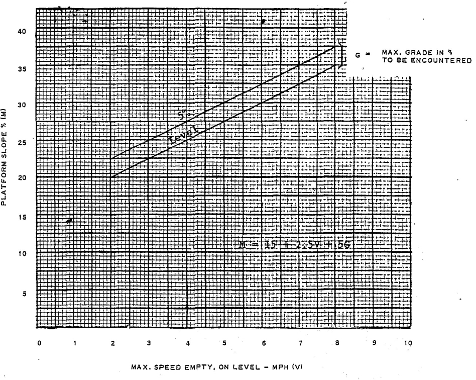
GRAPH E
25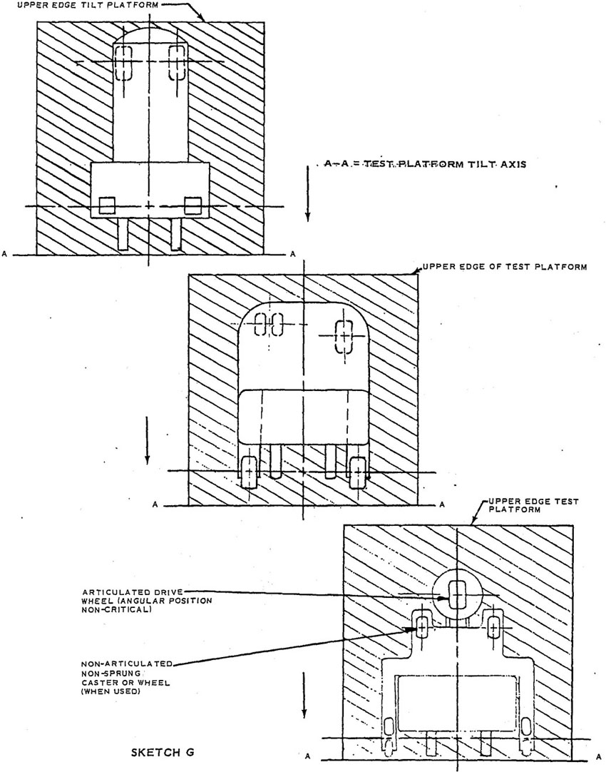
TILTING PLATFORM TEST – ORDER PICKER TRUCKS POSITIONING FOR TESTS #PO1,#OP2
26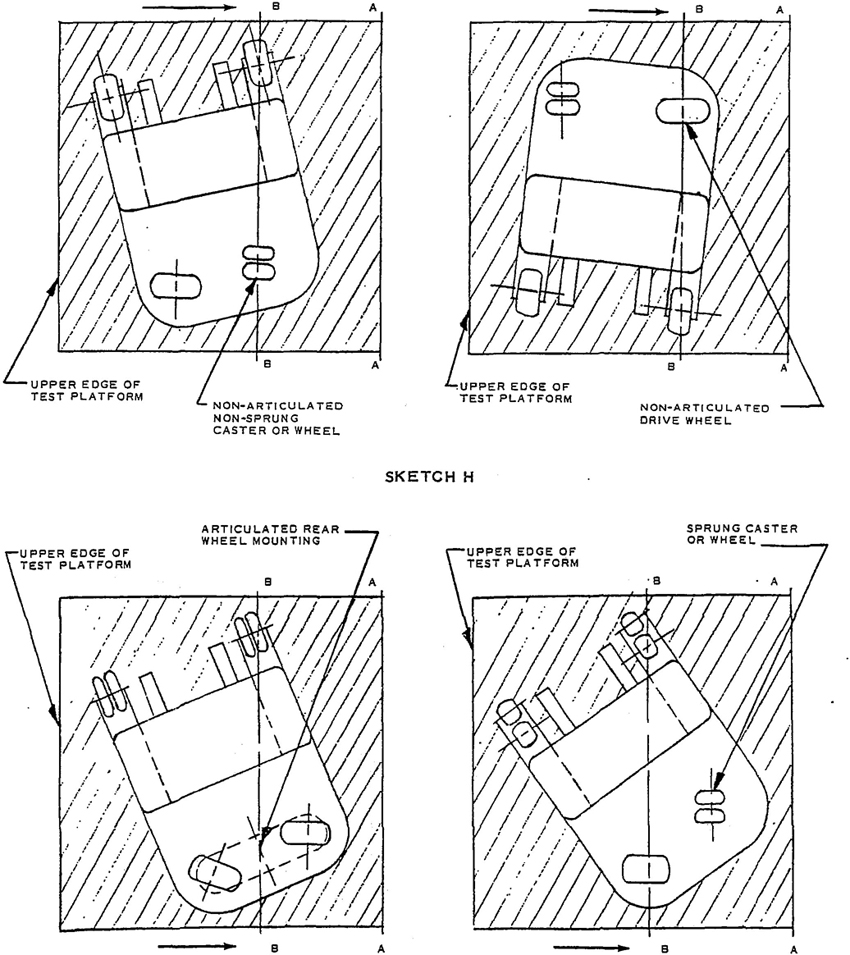
POSITIONING FOR TESTS#PO3,#OP4,#OP4A,#OP5
A–A = TEST PLATFORM TILT AXIS
B–B = TRUCK AXIS OF ORIGINAL TILT
POSITIONING FOR TESTS#PO3,#OP4,#OP4A,#OP5
A–A TEST PLATFORM TILT AXIS
POSITIONING FOR TESTSI#OP3,#OP4,#OP4A,#OP5
Truck is symmetrical and may be positioned either right or left hand
A–A = TEST PLATFORM TILT AXISM
B–B = TRUCK AXIS OF ORIGINAL TILT
A–A = TEST PLATFORM TILT AXIS
30It is also permissible to use two test loads of equal weight suspended from the ends of a transverse beam fastened to a framework supported by the forks as described in item 3, provided the loads are suspended from points equidistance from centerline of trucks, and provided that a straight line from one point to the other passes at a height above the forks and at a distance from front face of forks equal to the rated load center dimension before weight of test load has caused forks to deflect. The points of suspension must be free to pivot in any direction, such as by use of chain or cable. The transverse beam should be adequately braced to prevent deflection that would shift the load center.
The handle shall be mounted in such manner that the operator will steer with his left hand when facing the load end of the truck. An upward movement of the handle from the horizontal position shall steer the truck to the operator’s right when moving with load foremost.
The handle shall be mounted in such a manner that the operator will steer with his left hand when facing the load end of the truck. Movement of the handle to the right shall steer the truck to the operator’s right when moving the load foremost.
The handwheel shall be located to permit convenient operation with the left hand.
Clockwise rotation of the handwheel shall steer the truck to the operator’s right when the truck is moving forward. This is defined as “directional-forward steer.”
31Exception: In the past, considerable numbers of stand-up end-control rider
trucks employing a horizontal (vertical axis) handwheel have been built with directional-reverse steer (i.e. a control that causes a truck to turn to the operator’s right on clockwise rotation of the steering handwheel when the operator is facing away from the direction of normal forward travel.) For this reason directional-reverse steer is permissible for this type of truck.
When the truck is traveling with load trailing, clockwise rotation of the handwheel should steer the truck clockwise.
The handle shall be mounted in such a manner that the operator will steer with his left hand when sitting on and facing the front of the tractor. Clockwise movement of the handle shall steer the tractor to the operator’s right.
With the operator sitting on and facing the front of the tractor, clockwise rotation of the handwheel shall steer the tractor to the right.
With the walking operator facing in the direction of travel, with the load trailing, clockwise movement of the steering tongue shall steer the truck clockwise.
With the riding operator facing in the direction of travel, with the load trailing, clockwise movement of the steering tongue shall steer the truck clockwise.
A. Except for Hand/Rider Trucks, all steering controls shall be confined within the plan view outline of the truck, or guarded to prevent injury to the operator during movement of the controls when passing obstacles, walls, columns, etc.
B. Where steering must be accomplished with one hand, steering knobs are necessary for safe operation. Steering knobs, when used, shall be mounted within the periphery of the steering handwheel.
Steering handle shall be provided with suitable means to protect operator’s hands against injury from swinging doors, walls, columns, etc.
Service brakes shall enable the truck to develop a drawbar drag equal to a percent of the gross vehicle weight (with rated capacity load) per the second column of the table on next page, while the truck is being towed slowly in either direction. For brake pedals having a downward movement to apply brakes, the required brake performance shall be attained with a pedal force of not more than 125 pounds. For brake pedals having an upward movement to apply brakes, the required brake performance shall be attained with the normal upward force; however the brake linkage shall be such that the pedal will be fully depressed and the brakes released by a force of not more than 65 pounds.
For intermediate speeds, interpolate between values shown.
The above braking requirements are based on level floor operation. For safe operation on grades, the braking drawbar drag, as a percent of gross vehicle weight, must be at least equal to the percent of slope. This will provide enough braking force to hold the truck stationary on the grade, or to prevent it from gaining speed after starting down the grade.
Greater braking force is required to bring a truck to a stop on a down grade. The determination of what is safe stopping distance on a downgrade depends on many factors – such as, amount of clear space at bottom of grade, width of grade for evasive action, and possible traffic.
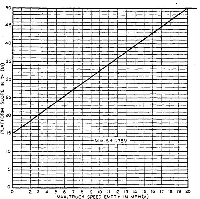
After deciding the required stopping distance on a down grade for safe operation, and a maximum speed that drivers will be permitted to operate when going down grade, the required braking force can be determined from Graph F for grades of 5, 10, 15, and 20 percent. Values for intermediate grades can be interpolated or calculated from the formula:
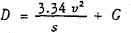
where D = Drawbar Drag as a percent of gross vehicle weight
v = Velocity in miles per hour
s = Distance in feet to stop
32G = Percent grade
| Maximum rated truck speed with rated capacity load in miles per hour on level surface v |
Required drawbar drag as percent of gross vehicle weight (with rated capacity load) D |
Approx. theoretical distance in feet, after brake has been applied, to stop from full speed on level surface s |
|---|---|---|
| 1 | 3% | 1.1 |
| 2 | 6% | 2.2 |
| 3 | 9% | 3.3 |
| 4 | 12% | 4.5 |
| 5 | 15% | 5.6 |
| 6 | 18% | 6.7 |
| 7 | 21% | 7.8 |
| 8 | 24% | 8.9 |
| 9 | 27% | 10.0 |
| 10 | 30% | 11.1 |
| Over 10 | 30% | Use formula  |
(This formula is reasonably accurate for grades up to 20 percent, since in this range the sine and tangent of the grade angle are approximately equal. The variation introduced by this simplification gives answers which are slightly conservative. For grades steeper than 20 percent, a more complicated formula may be used.)
Example 1: If a truck is to be permitted to operate down a 5 percent grade at a speed of 4 miles per hour, how much drawbar drag must be developed to stop the truck in a distance of 10 feet while still on the grade?
From Graph F for 5 percent grade, read from the 10 foot mark at bottom of graph up to the curve labeled 4 mph. Then read horizontally to left to find answer, 10.3 percent. This means that the service brake must be strong enough to enable the truck to develop a drawbar drag equal to 10.3 percent of the gross vehicle weight.
The answer may also be figured by means of the formula, as follows:
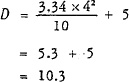
Answer: Brakes must be capable of developing a drawbar drag equal to 10.3 percent of the gross vehicle weight (with rated load).
Example 2: If a truck is to be permitted to operate down a 10 percent grade at a speed of 8 miles per hour, how much drawbar drag must be developed to stop the truck in a distance of 15 feet while still on the grade?
From Graph F for 10 percent grade, read from the 15 foot mark at bottom of graph up to curve labeled 8 mph. Then read horizontally to left to find answer, 24.2 percent of the gross vehicle weight (with rated load).
On certain types of trucks, the weight on the braking wheel (s) may be insufficient to attain drawbar drag values required for higher combinations of ramp and speed. In such cases, the truck involved should be limited to use and speeds within the limits of the drawbar drag attainable by test.
Means shall be provided to open the travel circuit when the operator leaves the truck.
Travel control shall be so arranged that the truck will move only when the direction control is actuated and will not move at a speed greater than inching speed unless control has been actuated for both speed and direction.
Accelerator, if foot operated, shall increase speed when depressed with the right foot.
Service brakes, if foot operated, shall be energized by depressing the control.
If a single pedal controls both acceleration and braking, depressing pedal should increase speed and releasing pedal should apply brakes, and the pedal shall be operated by the right foot.
Provision shall be made for locking control circuit(s) with a key to prevent unauthorized operation.
The service brake(s) shall be capable of
33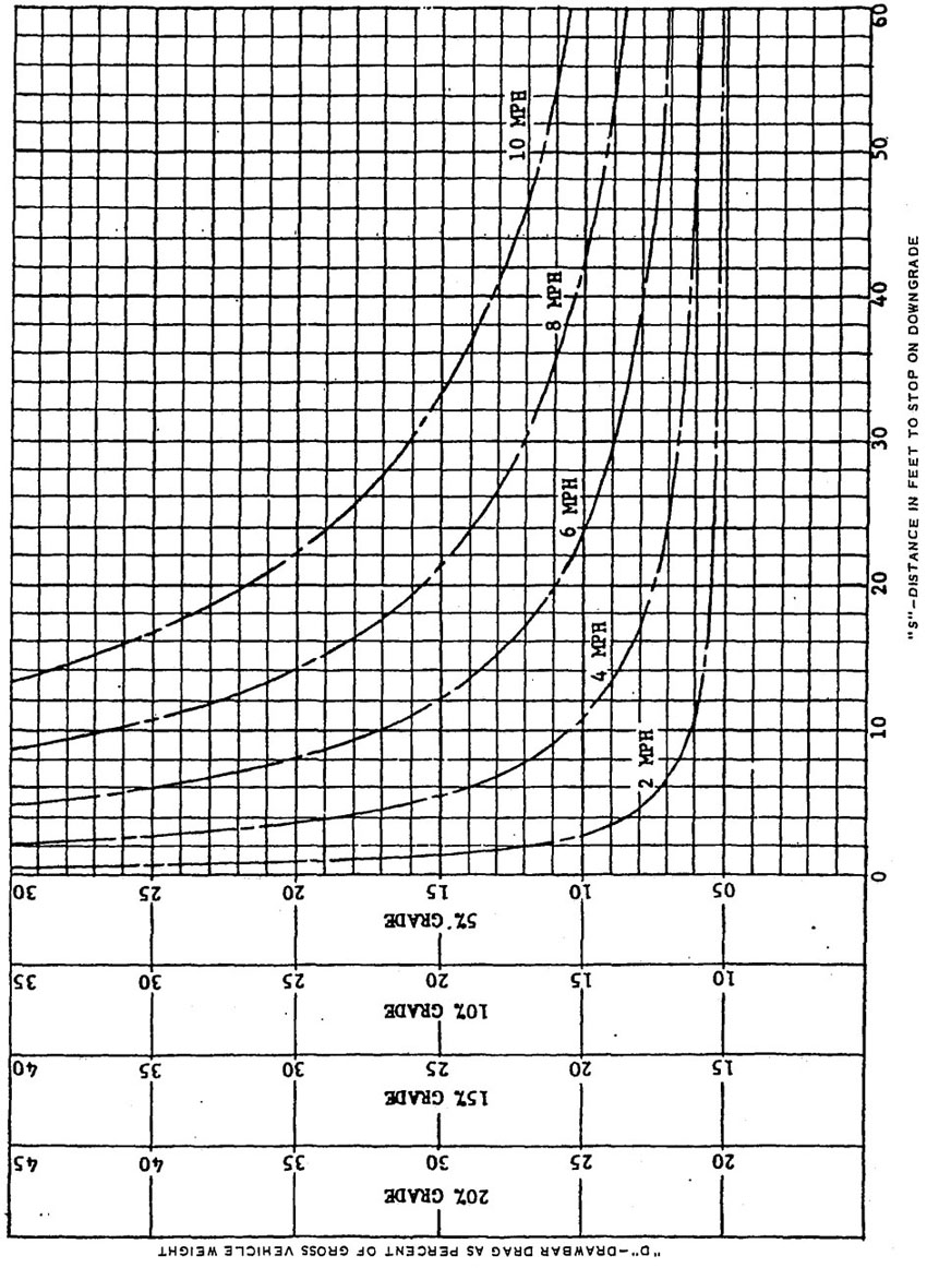
GRAPH F
34withstanding a brake pedal force of 250 pounds without failure of any component.
A parking brake (or mechanism) shall be provided and capable of holding the truck on the maximum grade which the truck can negotiate with rated load, or on a 15 percent grade, whichever is is the lesser.
The parking brake (or mechanism) shall be manually or automatically applied and shall remain applied until released by the operator.
Trucks having only manually operated parking brakes shall have a permanent marking ‘Warning – Apply Hand Brake (or Foot Brake) – Parking Brakes are not automatically applied.’
Means shall be provided to automatically open the travel circuit when the parking brake (or mechanism) is applied.
Means shall be provided so that the travel circuit can be activated only by releasing the parking brake and resetting the speed and/or directional control (s) when the operator assumes the driving position.
Provision shall be made for locking control circuit (s) with a key to prevent unauthorized operation.
For trucks having a downward movement of brake pedal to apply the service brake (s), the system shall be capable of withstanding a brake pedal force of 250 pounds without failure of any component.
For trucks having an upward movement of the brake pedal to apply the service brake (s), a force of 200 percent of the maximum possible setting of the spring shall not cause failure of any component.
A parking brake (or mechanism) shall be provided and capable of holding the truck on the maximum grade which the truck can negotiate with rated capacity load or on a 15 percent grade, whichever is the lesser.
The parking brake (or mechanism) shall be manually or automatically applied and shall remain applied until released by the operator.
Trucks having only manually operated parking brakes shall have a permanent marking ‘Warning – Apply Hand Brake (or Foot Brake) – Parking Brakes are not automatically applied.’
Travel control shall be so arranged that the truck will move only when the direction control is actuated and will not move at a speed greater than inching speed, unless control has been actuated for both speed and direction.
Service brakes, if foot operated, shall be energized by depressing the control.
If a combination clutch, and brake pedal is used, the initial pedal movement shall disengage the clutch and the final pedal movement shall apply the brakes and the pedal shall be operated by the left foot.
Accelerator, if foot operated, shall increase speed when depressed with the right foot.
If a combination pedal controls both acceleration and brakes, depressing the accelerator portion shall increase speed and depressing the brake portion shall apply the brakes, and the combination pedal shall be operated by the right foot.
Clutch pedal, if used, shall release clutch by depressing with left foot.
Provision shall be made for locking ignition with a key to prevent unauthorized operation.
The services brake shall be capable of withstanding a brake pedal force of 250 pounds without failure of any component.
A parking brake (or mechanism) shall be provided and capable of holding the truck on the maximum grade which the truck can negotiate with rated capacity load, or on a 15 percent grade, whichever is the lesser.
The parking brake (or mechanism) shall be manually or automatically applied and shall remain applied until released by the operator.
Accelerator, if foot operated, shall increase speed when depressed with the right foot.
Travel control shall be so arranged that the truck will not move until the direction control has been actuated and will not move, at a speed greater than inching speed, unless control has been actuated for both speed and direction.
Provision shall be made for locking ignition with a key to prevent unauthorized operation.
For trucks having a downward movement of brake pedal to apply the service brakes, the system shall be capable of withstanding a brake pedal force of 250 pounds without failure of any component.
For trucks having an upward movement of the brake pedal to apply the service brakes, a force of 200 percent of the maximum possible setting of the spring shall not cause failure of any component.
35A parking mechanism shall be provided and capable of holding the truck on the maximum grade which the truck can negotiate with rated capacity load, or on a 15 percent grade, whichever is the lesser.
The parking mechanism shall be manually or automatically applied and shall remain applied until released by the operator.
Forward and reverse motion of the truck shall be controlled or selected by means of a control device readily accessible when grasping handle grip on steering tongue. This control device shall operate directionally in one of the following manners:
The travel control shall be clearly and durably identified to indicate function and direction of motion.
Brake shall be applied and current to drive motor shall be cut off whenever the steering tongue is in approximately a vertical position, and the same conditions shall exist whenever the steering tongue is in approximately a horizontal position, or the brake shall be applied and current to drive motor cut off by release of the device normally used to control travel motion of the truck.
A parking brake (or mechanism) which may be a part of, or include the service brake(s), shall be provided and be capable of holding the truck on the maximum grade which the truck can negotiate with rated capacity load, or on a 10% grade, whichever is the lesser.
On a truck meeting the above requirements, provision may be made to permit the truck to be operated under control in a direction away from the control end of the truck when the steering tongue is in any position.
Controls (including remote) shall be provided which will de-activate travel controls when the operator leaves the truck. Travel controls shall be so arranged that the truck will move only when the direction control is actuated and will not move, at a speed greater than inching speed, unless control has been actuated for both direction and speed.
Automatic means should be provided to restrict the travel speed in accordance with good operating practices when the occupied operator platform is elevated above 24 inches.
Provision shall be made for locking controls with a key to prevent unauthorized operation.
Means shall be provided to render inoperative all operating controls other than those on the elevatable platform when the controls on the elevatable platform have been selected for use. Only one location of controls shall be capable of being operated at one time.
Means shall be provided for an operator on the elevatable platform to shut off the power to the truck.
A parking brake (or mechanism) shall be provided capable of holding the truck with rated capacity load on a 5 percent grade.
The parking brake (or mechanism) shall be manually or automatically applied and shall remain applied until released by the operator.
For trucks having a downward movement of brake pedal to apply the service brakes, the system shall be capable of withstanding a brake pedal force of 250 pounds without failure of any component.
For trucks having an upward movement of the brake pedal to apply the service brakes, a force of 200 percent of the maximum possible setting of the spring shall not cause failure of any component.
| Function | DIRECTION OF MOTION | |
|---|---|---|
| of load or equipment | Predominant motion of the operator's hand when actuating the control handle while facing the load | |
| Hoist | up down |
rearward or up forward or down |
| Tilt | rearward forward |
rearward or up* forward or down |
| Reach | retract extend |
rearward* forward |
| Clamp | clamp release |
rearward or up forward or down |
| Side Shift | right left |
rearward or up forward or down |
| Rotate Laterally |
clockwise counterclockwise |
rearward or up forward or down |
| Rotate Longitudinally |
rearward forward |
rearward or up* forward or down |
| *The sense of rotation of the control handle is intended to be in the same direction as the desired motion of the mast or load. | ||
To maintain stability with the lifting mechanism elevated, tilting should be controllable, smooth, and at reasonable speed. Consideration should be given to reducing tilt speeds on trucks with extra high lift.
Fork extensions or other attachments shall be suitably secured to prevent unintentional lifting or displacement on primary forks.
High-lift rider trucks shall be fitted with an overhead guard unless the customer otherwise requests. The overhead guard shall be of sufficient strength to support a uniformly distributed static load in accordance with the following table and Graph G, but it is not intended to withstand the impact of a falling capacity load.
37| Truck Capacity Rating | Static Test Load as a % of Truck Capacity Rating |
|---|---|
| Up to 5,000 lb | 200% of truck rating |
| Over 5,000 lb, up to 10,000 lb | 10,000 lb plus 100% of increment rating over 5,000 lb |
| Over 10,000 lb, up to 20,000 lb | 15,000 lb plus 50% of increment rating over 10,000 lb |
| Over 20,000 lb | Consult the Manufacturer |
It shall be capable of withstanding the impact of a 100 pound solid hardwood cube (or equivalent) dropped at random from a distance of 5 feet, 10 times without fracture or without permanent deflection exceeding ¾ inch.
It shall be constructed in a manner that does not interfere with good visibility, but openings in top shall not exceed 6 inches in one of the two dimensions, width or length. User should specify other size openings for special applications. It shall be large enough to extend over the operator under all normal circumstances of truck operation, including forward tilt.
In fork trucks equipped with a single tilt cylinder, provision shall be made to avoid injury to the operator by the overhead guard resulting from failure of this cylinder or associated parts.
In trucks where the operator is seated, a vertical clearance of at least 39 inches should be maintained from the point of maximum depression of the seat under the operator to the underside of the section of the guard under which the operator’s head moves during normal operation.
In trucks where the operator stands, a vertical clearance of at least 74 inches should be maintained from the platform where he stands to the underside of the section of the guard under which the operator's head moves during normal operation.
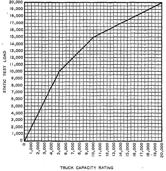
GRAPH G
38Under certain unusual operating conditions a stronger guard may be required. It is impractical to build a guard of sufficient strength to withstand the impact of a falling capacity load since such a guard would constitute a safety hazard because its structure would be so large that it might interfere with good visibility, and would weigh so much that it might make the truck top-heavy and unstable.
Load Backrest Extension should have height, width, and size of openings (not to exceed 6 inches in one of the two dimensions) sufficient to minimize the possibility of the load from falling toward the mast when the mast is in a position of maximum rearward tilt. It shall be constructed in a manner that does not interfere with good visibility.
Control pedals and control platforms stood on or engaged by the operator's feet should have non-skid surfaces.
Operator enclosures are not recommended because rapid and unobstructed ingress or egress for the operator is considered more desirable.
On double-end control baggage-type trucks or trucks which may be transported on short elevators, means should be provided to prevent unintentional folding of the operator's folding platform.
Additional operator enclosures may be provided in conjunction with the platform. If provided, they should permit easy ingress and egress from the platform.
Additional guards in conjunction with the platform are not recommended because of interference with the steering handle and with rapid and unobstructed egress for the operator.
Provision shall be made to prevent mechanical overtravel of motions such as hoist, tilt, boom, etc.
Tires extending beyond the confines of the truck should be provided with guards to preven the tires from throwing particles at the operator.
Every truck or tractor shall be equipped wit a warning horn, whistle, or gong, or other device.
Moving parts that represent a hazard shot be protected by suitable guards wherever possible. Moving parts that represent a hazard to operator in normal operating position, shall protected by suitable guards.
39Like other vehicles, powered industrial trucks can cause injury if improperly used or maintained.
Part III contains broad safety standards applicable to users and operators. If peculiar or unusual operating conditions indicate, plant safety departments should rewrite the applicable sections of Part III for the use of their employees.
Experience has shown that high lift trucks which comply with the stability standards stated in Part II are stable when properly operated. However, improper operation or faulty maintenance – both of which are beyond the control of the manufacturer or seller – may produce a condition of instability and defeat the purpose of the standard.
Some of the conditions which may affect stability are, ground and floor conditions, grade, speed, loading (trucks equipped with attachments behave as partially loaded trucks even when operated without a load on the attachment), battery weight, dynamic and static forces, and the judgment exercised by the operator.
Operators should be trained to adhere strictly to the operating instructions stated in Section 6 of this Part III and users should keep aisles, roadways, passageways, floors, and ramps in first class condition and free of loose objects.
Users shall give consideration to special operating conditions. The amount of forward and rearward tilt to be used is governed by the application involved. Although the use of maximum rearward tilt is allowable under certain conditions traveling with the load lowered, the stability of a truck as determined by the stability tests outlined in Part II, 406, does not encompass consideration for those operations involving excessive forward tilt at high elevations, not the operation of trucks with off-center loads and/or excessive rearward tilt at high elevations.
Some users may decide to establish, for their own use, stability requirements which will vary from those in Part II, 406. It is expected the requirements in Part II, 406, will serve as a guide for the user, working with the manufacturer, in establishing his own specialized requirements.
High Lift Rider trucks shall be fitted with an overhead guard manufactured in accordance with Part II, 421, of this standard, unless operating conditions do not permit.
40An overhead guard is intended to offer protection from the impact of small packages, boxes, bagged material, etc., representative of the job application, but not to withstand the impact of a falling capacity load. Where head room conditions limit the overall lowered height of the truck, normal overhead guard heights may be reduced or the overhead guard may be omitted. When it is necessary to omit the overhead guard, special attention should be given by the user and operator to conditions such as height and stability of loads and stacks, weight of individual units, and operating space including overhead obstructions.
If the type of load presents a hazard, the user shall equip fork trucks with a vertical load backrest extension manufactured in accordance with Part II, 422, of this standard.
Reinstalled batteries shall be properly positioned and secured in the truck.
Always pour acid into water; not water into acid.
Personnel maintaining batteries should wear protective clothing such as face shield, long sleeves, and gauntlet gloves.
The battery (or compartment) cover(s) shall be open to dissipate heat.
Powered industrial trucks for operation in hazardous areas shall be of the type as recommended in NFPA Standard No. 505 – Type Designations, Areas of Use, Maintenance, & Operation of Powered Industrial Trucks 1968, Part A
41and Part B. Trucks should be recognized as being built in accord with paragraphs 7 through 143 of UL Standards for Safety 558, Second Edition, September 1961 “Internal Combustion Engine-Powered Industrial Trucks” and paragraphs 7 through 130 and 132 through 187 of UL Standards for Safety 583, Fourth Edition, November 1956, Revised September 1960 “Power-Operated Industrial Trucks.” Trucks and areas of use should be marked in accordance with NFPA Standard No. 505 — 1968, Section 800.
Whenever aisles, roadways or passageways, floors and ramps are marked or defined, it is recommended that the suggestions contained in the USA Standard Safety Color Code for Marking Physical Hazards and the Identification of Certain Equipment Z53.1-1967 be followed.
It is suggested that powered industrial trucks be painted a color which will comply with the USA Standard Safety Color Code for Marking Physical Hazards and the Identification of Certain Equipment, Z53.1-1967.
9Dockboard recommendations also apply to bridge plates.
42When operating conditions dictate, the user should request the manufacturer to equip the trucks or tractors with visual warning devices such as lights or blinkers. Where noise levels are high, combinations of these may be required to insure adequate warning.
Operators of powered industrial trucks shall be physically qualified. An examination should be made on an annual basis and include such things as field of vision, hearing, depth perception, and reaction timing.
Only trained and authorized operators shall be permitted to operate a powered industrial truck. Methods shall be devised to train operators in the safe operation of powered industrial trucks. Badges or other visual indication of the operators authorization should be displayed at all times during work period.
10High lift order picker trucks are not normally intended for steep grade operation. Consult manufacturers operating instructions for recommended operating procedures.
44701 Powered industrial trucks may become hazardous if adequate maintenance is neglected. Therefore, adequate maintenance facilities, personnel, and procedures should be provided.
702 Maintenance and inspection of all powered industrial trucks shall be performed in conformance with the manufacturers recommendations and the following practices:
ATTACHMENT: A device other than conventional forks or load backrest extension, mounted permanently or removably on the elevating mechanism of a truck for handling the load. Popular types are fork extension clamps, rotating devices, side shifters, load stabilizers, rams, and booms.
BATTERY-ELECTRIC TRUCK: An electric truck in which the power source is a storage battery.
BRIDGE PLATE: A portable device for spanning the gap between two rail cars.
CANTILEVER TRUCK: A self-loading counter-balanced or noncounterbalanced truck, equipped with cantilever load engaging means such as forks (Fig. 1).
CARRIAGE: A support structure for forks or attachments, generally roller mounted traveling vertically within the mast of a cantilever truck.
CENTER CONTROL: The operator control position is located near the center of the truck.
COUNTERBALANCED TRUCK: A truck equipped with load engaging means wherein all the load during normal transporting is external to the polygon formed by the wheel contacts (Fig. 1).
DIESEL-ELECTRIC TRUCK: An electric truck in which the power source is a diesel engine driven generator.
DOCKBOARD: A portable or fixed device for spanning the gap or compensating for difference in level between loading platforms and carriers.
ELECTRIC TRUCK: A truck in which the principal energy is transmitted from power source to motor(s) in the form of electricity.
END CONTROL: The operator control position is located at the end opposite the load end of the truck.
FORKS: Horizontal tine-line projections, normally suspended from the carriage, for engaging and supporting loads.
FORK HEIGHT: The vertical distance from the floor-to the load carrying surface adjacent to the heel of the forks with mast vertical, and in the case of Reach Trucks, with the forks extended.
FORK LIFT TRUCK: A high lift self-loading truck, equipped with load carriage and forks for transporting and tiering loads.
GAS-ELECTRIC TRUCK: An electric truck in which the power source is a gasoline or LP gas-engine-driven generator.
HIGH-LIFT TRUCK: A self-loading truck equipped with an elevating mechanism designed to permit tiering. Popular types are high-lift fork truck, high-lift ram truck, high-lift boom truck, high-lift clamp truck, and high-lift platform truck (Fig. 1).
HIGH-LIFT PLATFORM TRUCK: A self-loading truck equipped with a load platform, intended primarily for transporting and tiering loaded skid platforms (Fig. 2).
INDUSTRIAL TRACTOR: A powered industrial vehicle designed primarily to draw one or more nonpowered trucks, trailers, or other mobile loads (Fig. 5).
INTERNAL COMBUSTION ENGINE TRUCK: A truck in which the power source is a gas or diesel engine.
LIFT TRUCK: See fork lift truck.
LOAD BACKREST EXTENSION: A device extending vertically from the fork carriage frame.
LOAD CENTER: The horizontal longitudinal distance from the intersection of the horizontal load-carrying surfaces and vertical load-engaging faces of the forks (or equivalent load positioning structure) to the center of gravity of the load.
LOW-LIFT TRUCK: A self-loading truck equipped with an elevating mechanism designed to raise the load sufficiently to permit horizontal movement. Popular types are low-lift platform truck and pallet truck (Fig. 3).
LOW-LIFT PLATFORM TRUCK: A self-loading truck equipped with a load platform intended primarily for transporting loaded skid platforms (Fig. 3).
MAST: The support member providing the guide-ways permitting vertical movement of the carriage. It is usually constructed in the form of channels or similar sections providing the supporting pathway for the carriage rollers.
MAXIMUM FORK HEIGHT: The fork height attainable in fully raised position when loaded.
MOTORIZED HAND TRUCK: A truck that is designed to be controlled by a pedestrian (Fig. 4).
MOTORIZED HAND/RIDER TRUCK: A dual purposed truck that is designed to be controlled
47by a pedestrian or by a riding operator (Fig. 6).
NARROW-AISLE TRUCK: A self-loading truck primarily intended for right-angle stacking in aisles narrower than those normally required by counterbalanced trucks of the same capacity (Fig. 10).
ORDER PICKER TRUCK, HIGH LIFT: A high lift truck controllable by the operator stationed on a platform movable with the load engaging means and intended for (manual) stock selection. The truck may be capable of self-loading and/or tiering.
OVERHEAD GUARD: A framework fitted to a truck over the head of a riding operator.
PALLET TRUCK: A self-loading, low-lift truck equipped with wheeled forks of dimensions to go between the top and bottom boards of a double-faced pallet and having wheels capable of lowering into spaces between the bottom boards so as to raise the pallet off the floor for transporting (Fig. 4).
PARKING BRAKE: A device to prevent the movement of a stationary vehicle.
POWERED INDUSTRIAL TRUCK: A mobile, power-driven vehicle used to carry, push, pull, lift, stack, or tier material.
REACH TRUCK: A self-loading truck, generally high-lift, having load-engaging means mounted so it can be extended forwardly under control to permit a load to be picked up and deposited in the extended position and transported in the retracted position (Fig. 7).
RIDER TRUCK: A truck that is designed to be controlled by a riding operator (Fig. 1).
SIDE LOADER: A self-loading truck, generally high-lift, having load engaging means mounted in such a manner that it can be extended laterally under control to permit a load to be picked up and deposited in the extended position and transported in the retracted position (Fig. 8).
STRADDLE TRUCK: A general class of cantilever truck with horizontal, structural wheel-supported members extending forward from the main body of the truck, generally high-lift, for picking up and hauling loads between its outrigger arms. (Fig. 10)
TRUCK: See Powered Industrial Truck.
TIERING: The process of placing one load on or above another.
48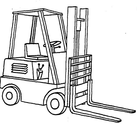
FIG. 1 – HIGH-LIFT TRUCK
– COUNTERBALANCED TRUCK
– CANTILEVER TRUCK
– RIDER TRUCK
– FORK LIFT TRUCK
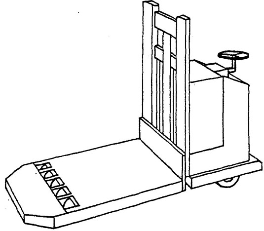
FIG. 2 – HIGH-LIFT TRUCK
– HIGH-LIFT PLATFORM TRUCK
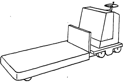
FIG. 3 – LOW-LIFT TRUCK
– LOW-LIFT PLATFORM TRUCK
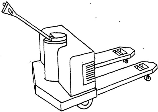
FIG. 4 – MOTORIZED HAND TRUCK
– PALLET TRUCK
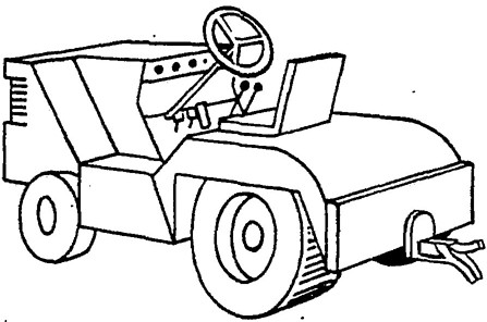
FIG. 5 – INDUSTRIAL TRACTOR
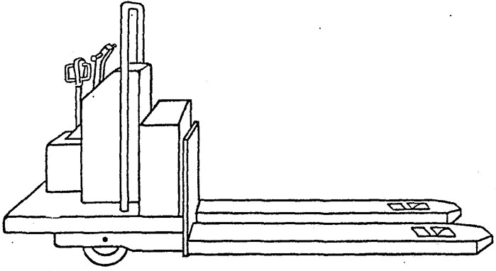
FIG. 6 – MOTORIZED HAND/RIDER TRUCK
50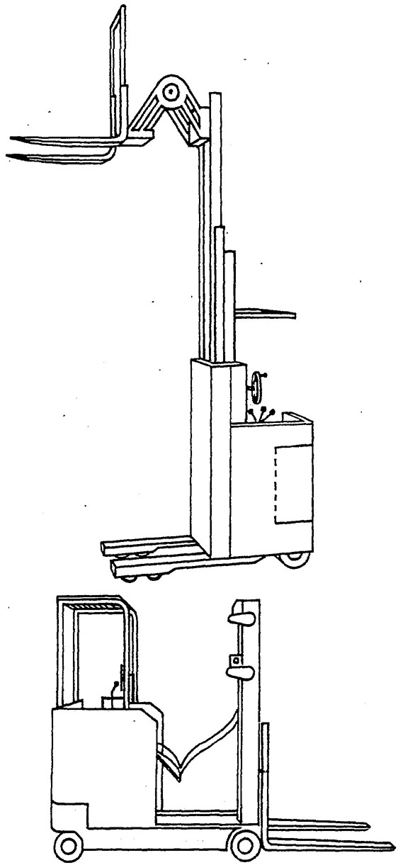
FIG. 7 – REACH TRUCK
51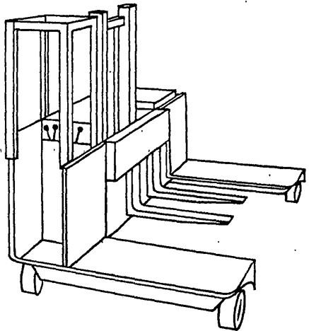
FIG. 8 – SIDE-LOADER TRUCK
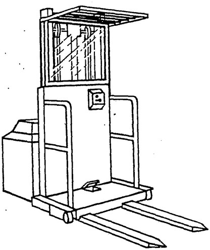
FIG. 9 – ORDER PICKER TRUCK, HIGH LIFT
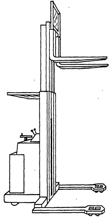
FIG. 10 – NARROW-AISLE TRUCK
– STRADDLE TRUCK