In order to promote public education and public safety, equal justice for all, a better informed citizenry, the rule of law, world trade and world peace, this legal document is hereby made available on a noncommercial basis, as it is the right of all humans to know and speak the laws that govern them.
SUPERSEDED
DERRICKS
ANSI B30.6 - 1969
Partial Revision of ANSI B30.2–1943
Sponsored by
Naval Facilities Engineering Command,
U.S. Department of the Navy
The American Society of Mechanical Engineers
Published by
THE AMERICAN SOCIETY OF MECHANICAL ENGINEERS
United Engineering Center 345 East 47th Street New York, N. Y. 10017
iCopyright, ©, 1970, by
THE AMERICAN SOCIETY OF MECHANICAL ENGINEERS
Printed In U.S.A.
This American National Standard Safety Code for Cranes, Derricks, Hoists, Jacks, and Slings has been developed under the procedures of the American National Standards Institute, formerly the United States of America Standards Institute. This specific code had its beginning in December 1916, when a Code of Safety Standards for Cranes, prepared by an ASME committee on the Protection of Industrial Workers, was presented to the annual meeting of the ASME.
Meetings and discussions regarding safety on cranes, derricks, and hoists were held from 1920 to 1925, involving the ASME Safety Code Correlating Committee, the Association of Iron and Steel Electrical Engineers, the American Museum of Safety, The American Engineering Standards Committee (later changed to American Standards Association and subsequently to the USA Standards Institute), Department of Labor, State of New Jersey, Department of Labor and Industry, State of Pennsylvania, and Locomotive Crane Manufacturers Association. On June 11, 1925 the American Engineering Standards Committee approved the ASME Safety Code Correlating Committee’s recommendation and authorized the project with U.S. Department of the Navy, Bureau of Yards and Docks and the ASME as sponsors.
In March 1926 invitations were issued to 50 organizations to appoint representatives to a Sectional Committee. The call for organization of this Sectional Committee was sent out October 2, 1926 and the Committee organized November 4, 1926 with 57 members representing 29 national organizations. From the 8-page document, referred to in the first paragraph, came the Safety Code for Cranes, Derricks, and Hoists ASA B30.2-1943. This document was reaffirmed in 1952 and widely accepted as a Safety Standard.
Due to changes in design, advancement in techniques, and general interest of labor and industry in safety, the Sectional Committee, now known as the American National Standards Committee, under the joint sponsorship of the ASME and the Naval Facilities Engineering Command — U.S. Department of the Navy was reorganized on January 31, 1962 with 39 members representing 27 national organizations. At the time B30.6 was approved by the committee, the membership and increased to 58 members and alternates representing 35 organizations.
The format of the previous Code was changed so that separate Codes, each complete as to construction and installation; inspection, testing, and maintenance; and operation, will cover the different types of equipment included in the scope of B30.
This Code presents a coordinated set of rules which may serve as a guide to government and other regulatory bodies and municipal authorities responsible for the guarding and inspection of the equipment falling within its scope. The suggestions leading to accident prevention are given both as mandatory and advisory provisions and compliance with both types may be required by employers of their employees.
In addition to the roster of the USA Standards Committee on pages iv and v, recognition should be given to those members who because of change in affiliation, retirement, or death, are not listed but have made outstanding contributions to this Code; this would include: C. J. Schwarzer, W. D. Meals, W. M. Kennedy, G. K. Woodling.
This code, which was approved by the American National Standards Committee B30 and by the two sponsor organizations, was approved and designated as an American National Standard by the American National Standards Institute on December 18, 1969.
iii ivAMERICAN NATIONAL STANDARDS COMMITTEE B30, SAFETY CODE FOR CRANES, DERRICKS, HOISTS JACKS, AND SLINGS
H. G. Greiner*, Chairman J. A. Proctor, Vice Chairman
H. F. Reid, Secretary
AMERICAN FEDERATION OF LABOR AND CONGRESS OF INDUSTRIAL ORGANIZATIONS
Alan Burch, International Union of Operating Engineers, Washington, D. C.
AMERICAN FOUNDRYMEN’S SOCIETY
*H. G. Greiner, Whiting Corporation, Harvey, Illinois
AMERICAN INSTITUTE OF STEEL CONSTRUCTION, INC.
T. S. McKosky, Bethlehem Steel Corporation, Bethlehem, Pennsylvania
AMERICAN INSURANCE ASSOCIATION
C. F. Olander, Firemen’s Fund American Insurance Companies, New York, New York
Winston Trimmer, Alternate, Maryland Casualty Company, Chicago, Illinois
AMERICAN IRON AND STEEL INSTITUTE
D. D. Mateer, Sr., Jones & Laughlin Steel Corporation, Pittsburgh, Pennsylvania
J. S. Chapman, Alternate, Armco Steel Corporation, Middletown, Ohio
AMERICAN MUTUAL INSURANCE ALLIANCE
F. H. Deeg, American Mutual Insurance Alliance, Chicago, Illinois
AMERICAN SOCIETY FOR TESTING AND MATERIALS
H. F. Reid, The McKay Company, York, Pennsylvania
AMERICAN SOCIETY OF CIVIL ENGINEERS
W. G. Rapp, Larchmont, New York
D. B. Rees, Alternate, American Bridge Division, United States Steel Corporation, Pittsburgh, Pennsylvania
AMERICAN SOCIETY OF MECHANICAL ENGINEERS, THE
D. E. Andrews, The Cambridge Wire Cloth Company, Cambridge, Maryland
E. W. Bender, Jr., Technical Products Company, Folcroft, Pennsylvania
C. J. Manney, Columbus McKinnon Corporation, Tonawanda, New York
*K. F. Potter, American Hoist & Derrick Company, St. Paul, Minnesota
Lewis Price, Montour Falls, New York
AMERICAN SOCIETY OF SAFETY ENGINEERS
W. E. Muldrew, Union Carbide Corporation, Oak Ridge, Tennessee
W. W. King, Alternate, U. S. Army Engineering Division, Portland, Oregon
ASSOCIATED GENERAL CONTRACTORS OF AMERICA, INC.
A. L. Schmuhl, Associated General Contractors of America, Inc., Washington, D. C.
ASSOCIATION OF AMERICAN RAILROADS
J. W. Cummings, The Delaware & Hudson Railroad Corporation, Albany, New York
ASSOCIATION OF IRON AND STEEL ENGINEERS
Clair Sanford, Jones & Laughlin Steel Corporation, Pittsburgh, Pennsylvania
DIVISION OF INDUSTRIAL SAFETY-STATE OF CALIFORNIA
J. F. Hatton, Division of Industrial Safety, San Francisco, California
ELECTRIC OVERHEAD CRANE INSTITUTE, INC.
F. W. Wendelburg, Harnischfeger Corporation, Milwaukee, Wisconsin
J. H. Peritz, Alternate, Electric Overhead Crane Institute, Inc., Washington, D. C.
FACTORY MUTUAL ENGINEERING CORPORATION
J. A. Wilson, Factory Mutual Engineering Division, Norwood, Massachusetts
*Deceased
vHEAVY-SPECIALIZED CARRIERS CONFERENCE (CRANE AND RIGGING OPERATIONS)
H. W. Bigge, Bigge Crane & Rigging, San Leandro, California
H. L. Hoffman, Jr., Alternate, Hoffman Rigging & Crane Service, Inc., Belleville, New Jersey
INDUSTRIAL COMMISSION OF OHIO, THE
J. F. Ridenour, The Industrial Commission of Ohio, Columbus, Ohio
INSTITUTE OF ELECTRICAL AND ELECTRONICS ENGINEERS
Samuel Rifkin, General Electric Company, Schenectady, New York
INTERNATIONAL ASSOCIATION OF GOVERNMENTAL LABOR OFFICIALS
A. C. Isola, New York State Department of Labor, New York, New York
Joseph Alleva, Alternate, New York Department of Labor, Albany, New York
INTERNATIONAL MATERIAL MANAGEMENT SOCIETY
A. C. Engel, Ferdon Equipment Company, Union, New Jersey
JACK INSTITUTE, THE
C. I. Munroe, Jr., Dura Corporation, Springfield, Illinois
R. M. Byrne, The Jack Institute, New York, New York
MASSACHUSETTS DEPARTMENT OF LABOR AND INDUSTRIES
A. C. Sinclair, Massachusetts Department of Labor, Boston, Massachusetts
F. A. Alexander, Alternate, Massachusetts Department of Labor, Boston, Massachusetts
NATIONAL ASSOCIATION OF CHAIN MANUFACTURERS
H. F. Reid, The McKay Company, York, Pennsylvania
NATIONAL BUREAU OF STANDARDS
W. J. Meese, National Bureau of Standards, U. S. Department of Commerce, Washington, D. C.
NATIONAL CONSTRUCTORS ASSOCIATION
E. D. Bearup, The Lummus Company, Newark, New Jersey
C. R. Mattson, Alternate, Dravo Corporation, Pittsburgh, Pennsylvania
NATIONAL ELECTRICAL MANUFACTURERS ASSOCIATION
H. A. Zollinger, Westinghouse Electric Corporation, Buffalo, New York
A. H. Myles, Alternate, Square D Company, Cleveland, Ohio
W. A. Samsonoff, Alternate, National Electrical Manufacturers Association, New York, New York
NATIONAL SAFETY COUNCIL
B. N. Carlson, United States Steel Corporation, Pittsburgh, Pennsylavania
J. W. Tysse, Republic Steel Corporation, Cleveland, Ohio
Charles Popke, Alternate, National Safety Council, Chicago, Illinois
POWER CRANE AND SHOVEL ASSOCIATION
R. J. Bushong, The Thew–Lorain Division of Koehring Company, Lora in, Ohio
Trevor Davidson, Alternate, Burcyrus–Erie Company, South Milwaukee, Wisconsin
SOCIETY OF AUTOMOTIVE ENGINEERS, INC.
F. J. Strnad, Link–Belt Speeder Corporation, Cedar Rapids, Iowa
C. R. Thompson, Alternate, Schield Bantam Company, Division of Koehring Company, Waverly, Iowa
UNITED STATES AIR FORCE
C. H. Reinertsen, Warner Robins Air Material Area, Robins Air Force Base, Georgia
N. C. Chapman, Alternate, Warner Robins Air Material Area, Robins Air Force Base, Georgia
UNITED STATES DEPARTMENT OF THE ARMY
W. F. Noser, Office of the Chief of Engineers, Department of the Army, Washington, D. C.
UNITED STATES DEPARTMENT OF LABOR
J. A. Proctor, U. S. Department of Labor, Bureau of Labor Standards, Washington, D. C.
E. L. Newmon, Alternate, U. S. Department of Labor, Bureau of Labor Standards, Washington, D. C.
UNITED STATES DEPARTMENT OF THE NAVY
L. T. Watson, Naval Facilities Engineering Command, Great Lakes, Illinois
E. W. Wheeler, Alternate, Naval Facilities Engineering Command, Washington, D. C.
WIRE ROPE TECHNICAL BOARD
F. A. Canfield, Wire Rope Corporation of America, St. Joseph, Missouri
| INTRODUCTION | Page | ||
| General | 1 | ||
| Section I Scope | 1 | ||
| Section II Purpose | 1 | ||
| Section III Exceptions and Interpretations | 2 | ||
| Section IV New and Old Derricks | 2 | ||
| Section V Mandatory and Advisory Rules | 2 | ||
| CHAPTER 6-0 | |||
| 6-0.1 Scope of B30.6 | 3 | ||
| 6-0.2 Definitions | 3 | ||
| CHAPTER 6-1 | |||
| 6-1.1 Load Ratings | 6 | ||
| 6-1.1.1 Basis | 6 | ||
| 6-1.1.2 Rated Load Marking | 6 | ||
| 6-1.2 Construction | 6 | ||
| 6-1.2.1 General | 6 | ||
| 6-1.2.2 Guy Derricks | 6 | ||
| 6-1.2.3 Stiff Leg Derrick | 6 | ||
| 6-1.3 Ropes and Reeving Accessories | 7 | ||
| 6-1.3.1 Guy Ropes | 7 | ||
| 6-1.3.2 Boom Hoist Ropes | 7 | ||
| 6-1.3.3 Main Hoist Ropes | 7 | ||
| 6-1.3.4 Reeving Accessories | 7 | ||
| 6-1.3.5 Sheaves | 7 | ||
| 6-1.4 Anchoring and Guying | 8 | ||
| 6-1.4.1 Guy Derrick | 8 | ||
| 6-1.4.2 Stiff Leg Derricks | 8 | ||
| 6-1.5 Hoist | 8 | ||
| 6-1.6 General Requirements | 8 | ||
| 6-1.6.1 Guards | 8 | ||
| 6-1.6.2 Lubrication | 8 | ||
| 6-1.6.3 Hooks | 8 | ||
| CHAPTER 6-2 | |||
| 6-2.1 Inspection | 9 | ||
| 6-2.1.1 Inspection Classification | 9 | ||
| 6-2.1.2 Frequent Inspection | 9 | ||
| 6-2.1.3 Periodic Inspection | 9 | ||
| 6-2.1.4 Derricks Not in Regular Use | 9 vii | ||
| 6-2.1.5 Inspection Records | 10 | ||
| 6-2.2 Testing | 10 | ||
| 6-2.2.1 Operational Tests | 10 | ||
| 6-2.3 Maintenance | 10 | ||
| 6-2.3.1 Preventive Maintenance | 10 | ||
| 6-2.3.2 Maintenance Procedure | 10 | ||
| 6-2.3.3 Adjustments and Repairs | 10 | ||
| 6-2.3.4 Lubrication | 11 | ||
| 6-2.4 Rope Inspection Replacement and Maintenance | 11 | ||
| 6-2.4.1 Inspection | 11 | ||
| 6-2.4.2 Rope Replacement | 11 | ||
| 6-2.4.3 Rope Maintenance | 12 | ||
| CHAPTER 6-3 | |||
| 6-3.1 Director (Designated Individual in Charge of Derrick Operations) Qualifications and Operating Practices | 13 | ||
| 6-3.1.1 Operations of Derricks | 13 | ||
| 6-3.1.2 Qualifications for Designated Individuals in Charge of Derrick Operations | 13 | ||
| 6-3.1.3 Practices of Designated Individuals Directing Operations | 13 | ||
| 6-3.2 Operator Qualifications and Operating Practices | 13 | ||
| 6-3.2.1 Operators | 13 | ||
| 6-3.2.2 Qualifications for Operators | 13 | ||
| 6-3.2.3 Operating Practices | 13 | ||
| 6-3.3 Handling the Load | 14 | ||
| 6-3.3.1 Size of Load | 14 | ||
| 6-3.3.2 Attaching the Load | 14 | ||
| 6-3.3.3 Moving the Load | 14 | ||
| 6-3.3.4 Holding the Load | 15 | ||
| 6-3.3.5 Use of Winch Heads | 15 | ||
| 6-3.3.6 Securing Boom | 15 | ||
| 6-3.4 Signals | 15 | ||
| 6-3.4.1 Standard Signals | 15 | ||
| 6-3.4.2 Hand Signals | 15 | ||
| 6-3.4.3 Bell Signals | 15 | ||
| 6-3.4.4 Special Signals | 15 | ||
| 6-3.4.5 Instructions | 15 | ||
| 6-3.5 Miscellaneous | 16 | ||
| 6-3.5.1 Fire Extinguishers | 16 | ||
| 6-3.5.2 Refueling | 16 | ||
| 6-3.5.3 Operating Near Electric Power Lines | 16 | ||
| 6-3.5.4 Cab or Operating Enclosure | 16 | ||
AMERICAN NATIONAL STANDARD
SAFETY CODES FOR CRANES, DERRICKS HOISTS, JACKS, AND SLINGS
This Code is one of a series of safety codes on various subjects which have been formulated under the general suspices of the USA Standards Institute. One purpose of the Code is to serve as a guide to governmental authorities having jurisdiction over the subjects within the scope of the Code. It is expected, however, that the Code will find a major application in industry, serving as a guide to both manufacturers of equipment and to the purchasers and users of the equipment.
For the convenience of the user, the Code has been divided into separate volumes such as the following:
B30.1 Jacks
B30.2 Overhead and Gantry Cranes1
B30.3 Hammerhead, Jib and Pillar Jib Cranes
B30.4 Portal, Tower, and Pillar Cranes
B30.5 Crawler, Locomotive, and Truck Cranes
B30.6 Derricks
B30.7 Hoists
B30.8 Floating Cranes and Floating Derricks
B30.9 Slings
B30.10 Hooks
B30.11 Monorail Cranes
B30.12 Helicopter Hoists
B30.13 Stacker Cranes
B30.14 Side Boom Cranes
B30.15 Hydraulic Cranes
B30.16 Overhead Hoists
If adopted for governmental use, the references to other national codes in the specific volumes may be changed to refer to the corresponding regulations of the governmental authorities.
The use of cranes, derricks, hoists, jacks, and slings is subject to certain hazards that cannot be met by mechanical means, but only by the exercise of intelligence, care, and common sense. It is therefore essential to have competent and careful operators, physically and mentally fit, thoroughly trained to the safe operation of the equipment and the handling of the loads. Serious hazards are overloading, dropping or slipping of the load caused by improper hitching or slinging, obstruction to the free passage of the load, using equipment for a purpose for which it was not intended or designed.
The standards committe fully realizes the importance of proper factors of safety, minimum or maximum sizes, and other limiting dimensions of wire rope and their fastenings, sheaves, drums, and similar equipment covered by the Code, all of which are closely connected with safety. Safe sizes, strengths, and similar criteria are dependent on many different factors, often varying with the installation and user. These factors also depend on the condition of the equipment or material; on the loads; on the acceleration, or speed of the ropes, sheaves or drums; on the type of attachments; on the number, size, and arrangement of sheaves, or other parts; on weather and other atmospheric conditions tending toward corosion, or wear; and on other variable factors that must be considered in each individual case. The rules given in the Code must be interpreted accordingly and judgment used in the determining application.
The standards committee will be glad to receive criticisms of the Code requirements and suggestions for its improvement, especially such as are based on actual experience in the application of the rules. Revised editions will be issued from the to time with such changes as experience in its application and improvements in the arts may dictate.
1This Code is designated B30.2.0 in the title only, on a temporary basis until revision of the B30.2—1943 has been completed.
1This Code applies to the construction, installation, inspection, maintenance, and operation of jacks; power-operated cranes; crane runways; power-operated overhead hoists and their runways; and slings.
This Code does not apply to any crane, derrick, or hoist having a maximum rated capacity of one ton or less, or to railway or automobile wrecking cranes, skip hoists, hoist–like units used for horizontal pulling only, mine hoists, conveyors, or to shovels, dragline excavators or back hoes, or to equipment within the scope of American National Standards Committee A92 Mobile Scaffolds, Towers, and Platforms. Within the above limitations this Code also shall be applied to cranes, derricks, and hoists used on construction work.
This Code is designed (1) to guard against and minimize injury to workers and otherwise provide for the protection of life, limb, and property by prescribing minimum safety requirements, (2) to provide direction to owners, employers, supervisors, and other concerned with, or responsible for, its application, and (3) to guide governments and other regulatory bodies in the development, promulgation, and enforcement of appropriate safety directives.
In case of practical difficulties or new developments, or unnecessary hardship, the administrative or regulatory authority may grant exceptions from the literal requirements or permit the use of other devices or methods, but only when it is clearly evident that an equivalent degree of protection is thereby secured.1
One year after the date on which this Code becomes effective, all new derricks shall conform to these rules. Derricks manufactured prior to that date should be modified to conform to these rules, unless it can be shown that the derrick cannot feasibly or economically be altered and that the derrick substantially complies with the requirements of the Code.
Mandatory rules of this Code are characterized by the use of the word “shall.” If a rule is of an advisory nature it is indicated by the use of the word “should” or is stated as a recommendation.
1To secure uniform application and interpretation of this Code, administrative or regulatory authorities are urged, before rendering decisions on disputed points, to consult the committee which formulated it through the office of The American Society of Mechanical Engineers, United Engineering Center, 345 East 47th Street, New York, New York 100 17.
26-0.1.1 Within the general scope, defined in Section I, B30.6 applies to guy, stiff-leg, basket, breast, gin-pole, Chicago Boom and A-frame derricks of the stationary type, capable of handling loads at variable reaches and powered by hoists through systems of rope reeving, used to perform lifting hook work, single or multiple line bucket work, grab, grapple, and magnet work. Derricks may be permanently installed or installed for temporary use as in construction work. The requirements of B30.6 also apply to any modification of these types which retain their fundamental features, except as specified for Floating Derricks in B30.8.
6-0.2.1 Types of Equipment
6-0.2.1.1 Derrick. An apparatus consisting of a mast or equivalent member held at the head by guys or braces, with or without a boom, for use with a hoisting mechanism and operating ropes.
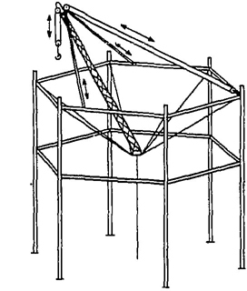
6.0.2.1.2 A-Frame Derrick. A derrick in which the boom is hinged from a cross member between the bottom ends of two upright members spread apart at the lower ends and joined at the top; the boom point secured to the junction of the side members, and the side members are braced or guyed from this junction point.
A-FRAME
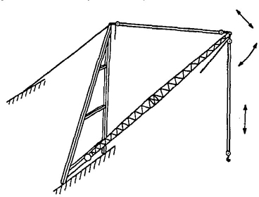
6-0.2.1.3 Basket Derrick. A derrick without a boom, similar to a gin pole with its base supported by ropes attached to corner posts or other parts of the structure. The base is at a lower elevation than its supports. The location of the base of a basket derrick can be changed by varying the length of the rope supports. The top of the pole is secured with multiple reeved guys to position the top of the pole to the desired location by varying the length of the upper guy lines. The load is raised and lowered by ropes through a sheave or block secured to the top of the pole.
BASKET
6-0.2.1.4 Breast Derrick. A derrick without a boom. The mast consists of two side members spread farther apart at the base than at the top and tied together at top and bottom by rigid members. The mast is prevented from tipping forward by guys connected to its top. The load is raised and lowered by ropes through a sheave or block secured to the top crosspiece.
BREAST
36-0.2.1.5 Chicago Boom Derrick. A boom which is attached to a structure, an outside upright member of the structure serving as the mast, and the boom being stepped in a fixed socket clamped to the upright. The derrick is complete with load, boom, and boom point swing line falls.
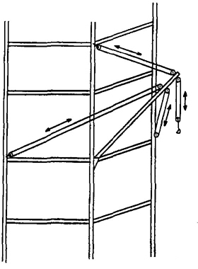
CHICAGO BOOM
6-0.2.1.6 Gin Pole Derrick. A derrick without a boom. Its guys are so arranged from its top to permit leaning the mast in any direction. The load is raised and lowered by ropes reeved through sheaves or blocks at the top of the most.
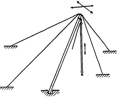
GIN POLE
6-0.2.1.7 Guy Derrick. A fixed derrick consisting of a mast capable of being rotated, supported in a vertical position by guys, and a boom whose bottom end is hinged or pivoted to move in a vertical plane with a reeved rope between the head of the mast and the boom point for raising and lowering the boom, and a reeved rope from the boom point for raising and lowering the load.
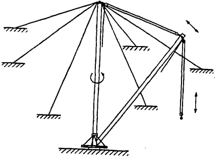
GUY
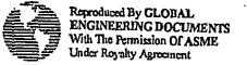
6-0.2.1.8 Shearleg Derrick. A derrick without a boom and similar to a Breast Derrick. The mast, wide at the bottom and narrow at the top, is hinged at the bottom and has its top secured by a multiple reeved guy to permit handling loads at various radii by means of load tackle suspended from the mast top.
6-0.2.1.9 Stiffleg Derrick. A derrick similar to a guy derrick except that the mast is supported or held in place by two or more stiff members, called stifflegs, which are capable of resisting either tensile or compressive forces. Sills are generally provided to connect the lower ends of the stifflegs to the foot of the mast.
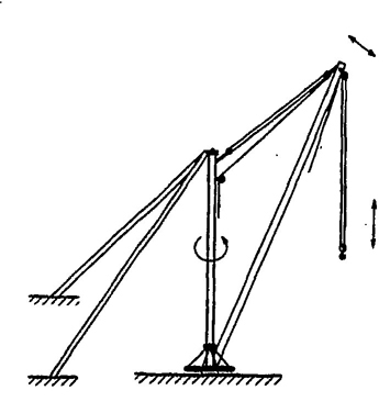
STIFF LEG
46-0.2.2 General
6-0.2.2.1 Administrative or Regulatory Authority. Governmental Agency or the Employer in the absence of governmental jurisdiction.
6-0.2.2.2 Appointed. Assigned specific responsibilities by the employer or the employer's representative.
6-0.2.2.3 Approved. Accepted as satisfactory by a duly constituted administrative or regulatory authority.
6-0.2.2.4 Authorized. Approved by a duly constituted administrative or regulatory authority.
6-0.2.2.5 Boom. A timber or metal section or strut, pivoted or hinged at the heel (lower end) at a location fixed in height on a frame or mast or vertical member, and with its point (upper end) supported by chains, ropes, or rods to the upper end of the frame, mast, or vertical member. A rope for raising and lowering the load is reeved through sheaves or a block at the boom point. The length of the boom shall be taken as the straight line distance between the axis of the foot pin and the axis of the boom point sheave pin, or where used, the axis of the upper load block attachment pin.
6-0.2.2.6 Boom Horness. The block and sheave arrangement on the boom point to which the topping lift cable is reeved for lowering and raising the boom.
6-0.2.2.7 Boom Point. The outward end of the top section of the boom.
6-0.2.2.8 Derrick Bullwheel. A horizontal ring or wheel, fastened to the foot of a derrick, for the purpose of turning the derrick by means of ropes leading from this wheel to a powered drum.
6-0.2.2.9 Designated. Selected or assigned by the employer or employer's representative as being qualified to perform specific duties.
6-0.2.2.10 Eye. A loop formed at the end of a rope by securing the dead end to the live end at the base of the loop.
6-0.2.2.11 Fiddle Block. A block consisting of two sheaves in the same plane held in place by the same cheek plates.
6-0.2.2.12 Foot Bearing or Block (Sill Block). The lower support on which the mast rotates.
6-0.2.2.13 Gudgeon Pin. A pin connecting the mast cap to the mast allowing rotation of the mast.
6-0.2.2.14 Guy. A rope used to steady or secure the mast or other member in the desired position.
6-0.2.2.15 Load, Working. The external load, in pounds, applied to the derrick, including the weight of load attaching equipment such as load blocks, shackles and slings.
6-0.2.2.16 Load Block, Lower. The assembly of sheaves, pins, and frame suspended by the hoisting rope.
6-0.2.2.17 Load Block Upper. The assembly of sheaves, pins, and frame suspended from the boom.
6-0.2.2.18 Mast. The upright member of the derrick.
6-0.2.2.19 Mast Cap (Spider). The fitting at the top of the mast to which the guys are connected.
6-0.2.2.20 Reeving. A rope system in which the rope travels around drums and sheaves.
6-0.2.2.21 Rope. Refers to wire rope unless otherwise specified.
6-0.2.2.22 Safety Hook. A hook with a latch to prevent slings or load from accidentally slipping off the hook.
6-0.2.2.23 Side Loading. A load applied at an angle to the vertical plane of the boom.
6-0.2.2.24 Sill. A member connecting the foot block and stiffleg or a member connecting the lower ends of a double member mast.
6-0.2.2.25 Standby Derrick. A derrick not in regular service which is used occasionally or intermittently as required.
6-0.2.2.26 Stiff Leg. Rigid member supporting the mast at the head.
6-0.2.2.27 Swing. Rotation of the mast and/or boom for movements of loads in a horizontal direction about the axis of rotation.
56-1.1.1 Basis
Load ratings are dependent on such factors as anchorage, structural competence, rope strength, and hoist capacity.
6-1.1.2 Rated Load Marketing
a. For permanently installed derricks with fixed lengths of boom, guy, and mast, a substantial, durable and clearly legible rating chart shall be provided with each derrick and securely affixed where it is visible to personnel responsible for the safe operation of the equipment. The chart shall include but not necessarily be limited to the following data:
(1) Manufacturer’s approved load ratings at corresponding ranges of boom angle or operating radii.
(2) Specific lengths of components on which the load ratings are based.
(3) Required parts for hoist reeving. Size and construction of rope may be shown either on the rating chart or in the operating manual.
b. For non-permanent installations, the manufacturer shall provide sufficient information from which capacity charts can be prepared for the particular installation. The capacity charts shall be located either at the derrick or the job site office.
6-1.2.1 General
a. Derricks shall be constructed to adequately meet all stresses imposed on main members and components under normal operating conditions when properly installed and handling loads not exceeding manufacturer’s load ratings with recommended reeving.
b. Welding of critically stressed members shall conform to recommended practices of the American Welding Society as outlined in Specifications for Welded Highway and Railway Bridges AWS D2.0-66.*
6-1.2.2 Guy Derricks
a. The recommended minimum number of guys is six but in no case shall less than five be used. Preferably, the guys should be equally spaced around the mast. For exceptions, see Section III of the Introduction.
b. The manufacturer shall furnish complete information recommending:
(1) the number of guys;
(2) the spacing around the mast;
(3) the maximum vertical slope of all guys;
(4) the size, grade and construction of rope to be used in each.
c. The mast base shall permit free rotation of the mast with allowance for slight tilting of the mast caused by guy slack.
d. The mast cap shall:
(1) permit free rotation of the mast;
(2) adequately withstand tilting and cramping action imposed by the guy loads;
(3) be secured to the mast to prevent dis-engagement during erection;
(4) be provided with means for attachment of guy ropes.
6-1.2.3 Stiff Leg Derrick
a. The mast shall be supported in the vertical position by two stiff legs one end of each being connected to the top of the mast and the other end securely anchored. The stiff legs shall be capable of withstanding the loads imposed by the boom at any point within its range of swing.
b. The mast base shall:
(1) permit free rotation of mast;
(2) permit slight deflection of the mast without binding;
(3) provide means to prevent the mast from lifting out of its socket when the mast is in tension.
c. The stiff leg connecting member at the top of the mast shall:
*Published by the American Welding Society, 345 East 47th Street, New York N.Y. 10017.
6(1) permit free rotation of the mast;
(2) adequately withstand the loads imposed by the action of the stiff legs;
(3) be so secured as to oppose lift off forces at all times.
6-1.3.1 Guy Ropes
a. Guy ropes shall be of suitable size, grade and construction to withstand the maximum load imposed.
b. The nominal breaking strength of each rope shall be no less than three times the load applied to the rope.
c. Tie downs (kicker devices) which may be easily loosened shall have locknuts or other suitable provision to prevent loosening.
6-1.3.2 Boom Hoist Ropes
a. Boom hoist ropes shall be of suitable size, grade and construction to withstand the maximum load imposed.
b. The live rope reeving system in a boom suspension shall withstand the maximum load imposed and be of sufficient length to permit lowering the boom point to horizontal position with at least two full wraps of rope remaining on the hoist drum.
c. The nominal breaking strength of the most heavily loaded rope in a system shall be no less than three and a half times the load, applied to that rope.
6-1.3.3. Main Hoist Ropes
a. Main hoist ropes shall be of a suitable size, grade and construction to withstand the maximum load imposed.
b. Ropes in the main hoisting system shall be of sufficient length for the entire range of movement specified for the application with at least two full wraps of rope on the hoist drum at all times.
c. The nominal breaking strength of the most heavily loaded rope in a system shall be no less than three and a half times the load applied to that rope.
NOTE: The rope safety factors, as defined in paragraphs 6-1.3.1, 6-1.3.2, and 6-1.3.3 above, shall be determined on the basis of rope loads resulting from manufacturer’s capacity ratings, approved reeving, published nominal breaking strength of new rope with adequate consideration for frictional losses.
Ropes of material other than steel may be used only in accordance with the manufacturer’s recommendation.
6-1.3.4 Reeving Accessories
a. Socketing shall be done in the manner specified by the manufacturer of the assembly.
b. Rope end shall be anchored securely to the drum.
c. Eyes shall be made in an approved manner and rope thimbles should be used in the eye.
d. U-bolt clips shall have the U-bolt on the dead or short end, and the saddle on the live or long end of the rope. Spacing and number of all types of clips shall be in accordance with the clip manufacturer’s recommendation. Clips shall be drop-forged steel in all sizes manufactured commercially. When a newly installed rope has been in operation for an hour, all nuts on the clip bolts shall be retightened, and they should be checked for tightness at frequent intervals thereafter.
e. Swaged, compressed, or wedge-socket fittings shall be applied as recommended by the rope, derrick, or fitting manufacturer.
f. Where a half wedge socket is used it shall be of a positive locking type.
g. If a load is supported by more than one part of rope, the tension in the parts shall be equalized.
6-1.3.5 Sheaves
a. Sheave grooves shall be smooth and free from surface defects which could cause rope damage. The cross sectional radius at the bottom of the groove should be such as to form a close fitting saddle for the size rope used and the sides of the groove should be tapered outwardly to facilitate entrance of the rope into the groove. Flange corners should be rounded
7and the rims should run true about the axis of rotation.
b. Sheaves carrying ropes which can be momentarily unloaded shall be provided with close fitting guards or other suitable devices to guide the rope back into the groove when the load is applied again.
c. The sheaves in the lower load block shall be equipped with close-fitting guards that will prevent ropes from becoming fouled when the block is lying on the ground with ropes loose.
d. Means should be provided, if necessary, to prevent chafing of the ropes.
e. All running sheaves shall be equipped with means for lubrication. Permanently lubricated, sealed and/or shielded bearings shall be acceptable.
f. Boom and hoisting sheaves shall have pitch diameters not less than eighteen times the nominal diameter of the rope used.
g. Boom point sheaves should be provided with suitable guides to limit the offlead angle of the rope when entering the grooves from either side.
6-1.4.1 Guy Derricks
a. The mast base shall be securely anchored. Maximum horizontal and downward vertical thrusts encountered when handling rated loads with the particular guy slope and spacing stipulated for the application are among the design factors for which provision must be made.
b. The guys shall be secured to the ground or other firm anchorage. Maximum horizontal and vertical pulls encountered while handling rated loads with the particular guy slope and spacing stipulated for the application are among the factors for which provision must be made.
6-1.4.2 Stiff Leg Derricks
a. The mast base shall be securely anchored. Maximum horizontal and upward and downward vertical thrusts encountered while handling rated loads stipulated for the application with the particular stiff-leg spacing and slope are among the factors for which provision must be made.
b. The stiff legs shall be securely anchored. Maximum horizontal and vertical upward and downward thrusts encountered while handling rated loads with the particular stiff-leg arrangement stipulated for the application are among the factors for which provision must be made.
6-1.4.3 For permanent fixed installations the manufacturer shall provide data on the magnitude of all anchorage loads, referred to in 6-1.4.1 and 6-1.4.2, for the conditions stipulated for the application. For non-permanent installations such data shall be determined by the user.
6-1.5.1 The hoist shall be suitable for the derrick work intended and shall be securely anchored to prevent displacement from the imposed loads.
6-1.6.1 Guards
a. Exposed moving parts, such as gears, ropes, set screws, projecting keys, chains, chain sprockets, and reciprocating components, which constitute a hazard under normal operating conditions shall be guarded.
b. Guards shall be securely fastened.
c. Each guard shall be capable of supporting, without permanent distortion, the weight of a 200 pound man unless the guard is located where it is impossible for a man to step on it.
6-1.6.2 Lubrication
Lubricating points should be accessible without the necessity of removing guards or other parts.
6-1.6.3 Hooks
a. Hooks shall meet the manufacturer's recommendations and shall not be overloaded. If hooks are of the swivelling type, they should rotate freely.
b. Safety latch type hooks should be used wherever possible.
86-2.1.1 Inspection Classification
a. Initial Inspection. Prior to initial use all new and altered derricks shall be inspected to insure compliance with the provisions of this Code.
b. Inspection procedure for derricks in regular service is divided into two general classifications based upon the intervals at which inspection should be performed. The intervals in turn are dependent upon the nature of the critical components of the derrick and the degree of their exposure to wear, deterioration or malfunction. The two general classifications are herein designated as frequent and periodic with respective intervals between inspections as defined below:
(1) Frequent Inspection – Daily to monthly intervals.
(2) Periodic Inspection – One to twelve month intervals, or as specified by the manufacturer.
6-2.1.2 Frequent Inspection
Items such as the following shall be inspected for defects at intervals as defined in 6-2.1.1-b.1 or as specifically indicated, including observation during operation for any defects which might appear between regular inspections. Deficiencies shall be carefully examined and a determination made as to whether they constitute a safety hazard:
(1) All control mechanisms. Inspect daily for adjustment, wear, and lubrication.
(2) All chords and lacing. Inspect daily, visually.
(3) Tension in guys. Daily.
(4) Plumb of the mast.
(5) Deterioration or leakage in air or hydraulic systems. Daily.
(6) Derrick hooks for deformations or cracks; for hooks with cracks or having more than 15 per cent in excess of normal throat opening or more than 10 degree twist from the plane of the unbent hook, refer to 6—2.3.3-c.1
(7) Rope reeving; visual inspection for non-compliance with derrick manufacture's recommendations.
(8) Hoist brakes, clutches, and operating levers; check daily for proper functioning before beginning operations.
(9) Electrical apparatus for malfunctioning, signs of excessive deterioration, dirt, and moisture accumulation.
6-2.1.3 Periodic Inspection
a. Complete inspections of the derrick shall be performed at intervals as generally defined in 6-2.1.1-b.2 depending upon its activity, severity of service, and environment, or as specifically indicated below. These inspections shall include the requirements of 6-2.1.2 and in addition, items such as the following. Deficiencies shall be carefully examined and a determination made as to whether they constitute a safety hazard:
(1) Structural members for deformations, cracks and corrosion.
(2) Bolts or rivets for tightness.
(3) Parts such as pins, bearings, shafts, gears, sheaves, drums, rollers, locking and clamping devices, for wear, cracks and distortion.
(4) Gudgeon pin for cracks, wear and distortion each time the derrick is to be erected.
(5) Power plants for proper performance and compliance with applicable safety requirements.
(6) Hooks; magnetic particle or other suitable crack detecting inspection should be performed at least once each year.
b. Foundation or supports shall be inspected for continued ability to sustain the imposed loads.
6-2.1.4 Derricks Not in Regular Use
a. A derrick which has been idle for a period of one month or more, but less than six months, shall be given an inspection conforming with requirements of 6-2.1.2 and 6-2.4.1-c before placing in service.
9b. A derrick which has been idle for a period of over six months shall be given a complete inspection conforming with requirements of 6-2.1.2, 6-2.1.3 and 6-2.4.1-c before placing in service.
c. Stand-by derricks shall be inspected at least semiannually in accordance with requirements of 6-2.1.2 and 6-2.4.1-c. Those exposed to adverse environment should be inspected more frequently.
6-2.1.5 Inspection Records
Written, dated and signed inspection reports and records should be made on critical items such as hooks and ropes. Records should be readily available.
6-2.2.1 Operational Tests
a. Prior to initial use all new and altered derricks shall be tested to insure compliance with this Code including functions such as the following:
(1) Load hoisting and lowering.
(2) Boom up and down.
(3) Swing.
(4) Operation of clutches and brakes of hoist.
b. All anchorages shall be approved by the appointed person. Rock and hairpin anchorages may require special testing.
6-2.3.1 Preventive Maintenance
a. A preventive maintenance program based on the derrick manufacturer's recommendations shall be established. Dated and detailed records should be readily available.
b. It is recommended that replacement parts be obtained from the original equipment manufacturer.
6-2.3.2 Maintenance Procedure
a. Before adjustments and repairs are started on a derrick the following precautions shall be taken:
(1) The derrick to be repaired shall be arranged so it will cause the least interference with other equipment and operations in the area.
(2) All hoist drum dogs shall be engaged.
(3) Main or emergency switch locked in the open position, if electric hoist is used.
(4) Warning or out of order signs placed on the derrick and hoist.
(5) The repairs of booms of derricks shall either be made when the booms are lowered and adequately supported or safely tied off.
(6) A good communication system shall be set up between the hoist operator and the appointed individual in charge of derrick operations before any work on the equipment is started.
(7) Welding repairs shall be approved by an appointed person.
b. After adjustments and repairs have been made the derrick shall not be operated until all guards have been reinstalled, safety devices reactivated and maintenance equipment removed.
6-2.3.3 Adjustments and Repairs
a. Any unsafe conditions disclosed by the inspection and requirements of Section 6-2.1 shall be corrected before operation of the derrick is resumed. Adjustments and repairs shall be done only be designated personnel.
b. Adjustments shall be maintained to assure correct functioning of components. The following are examples:
(1) All functional operating mechanism.
(2) Tie-downs or anchorages.
(3) Signal system.
(4) Brakes and clutches.
(5) Power plants
(6) Guys.
c. Repairs or replacements shall be provided promptly as needed for safe operation. The following are examples:
10(1) Hooks showing defects described in 6-2.1.2-a.6 shall be discarded. Repairs by welding or reshaping are not generally recommended.
(2) All critical parts which are cracked, broken, bent or excessively worn.
(3) Pitted or burned electrical contacts should be corrected only by replacement and in sets. Controller parts should be lubricated as recommended by the manufacturer.
d. All replacement and repaired parts shall have at least the original safety factor.
6-2.3.4 Lubrication
a. All moving parts of the derrick and hoist, for which lubrication is specified, including rope and chain, shall be regularly lubricated. Lubricating systems shall be checked for proper delivery of lubricant. Particular care should be taken to follow manufacturer's recommendations as to points and frequency of lubrication, maintenance of lubricant levels and types of lubricant to be used.
b. Machinery shall be stationary while lubricants are being applied and protection provided as called for in 6-2.3.2-a.1, .2, and .3 unless equipped for automatic lubrication.
6-2.4.1 Inspection
a. All running ropes in continuous service should be visually inspected once every working day. A through inspection of all ropes in use shall be made at least once a month and a full written, dated and signed report of rope condition kept on file where readily available. All inspections shall be performed by an appointed or authorized person. Any deterioration, resulting in appreciable loss of original strength, such as described below shall be carefully noted and determination made as to whether further use of the rope would constitute a safety hazard:
(1) Reduction of rope diameter below nominal diameter due to loss of core support, internal or external corrosion or wear of outside wires
(2) A number of broken outside wires and the degree of distribution or concentration of such broken wires.
(3) Worn outside wires.
(4) Corroded or broken wires at end connections.
(5) Corroded, cracked, bent, worn, or improperly applied end connections.
(6) Severe kinking, crushing, cutting, or unstranding.
b. Heavy wear and/or broken wires may occur in sections in contact with equalizer sheaves or other sheaves where rope travel is limited, or with saddles. Particular care shall be taken to inspect ropes at these locations.
c. All rope which has been idle for a period of a month or more due to shutdown or storage of a derrick on which it is installed shall be given a thorough inspection before it is placed in service. This inspection shall be performed by an appointed or authorized person whose approval shall be required for further use of the rope. A written and dated report of the rope condition shall be filed.
d. Particular care shall be taken in the inspection of nonrotating rope.
6-2.4.2 Rope Replacement
a. No precise rules can be given for determination of the exact time for replacement of rope, since many variable factors are involved. Safety in this respect depends largely upon the use of good judgement by an appointed or authorized person in evaluating remaining strength in a used rope after allowance for deterioration disclosed by inspection. Safety of rope operation depends upon this remaining strength.
b. Conditions such as the following should be sufficient reason for questioning rope safety and for consideration of replacement.
(1) In running ropes, six randomly distributed broken wires in one rope lay. or three broken wires in one strand in one rope lay.
11(2) Wear of one-third of the original diameter of outside individual wires.
(3) Kinking, crushing, bird caging or any other damage resulting in distortion of the rope structure.
(4) Evidence of any heat damage from any cause.
(5) Reductions from nominal diameter of more than:
3/64 inch for diameters to and including 3/4 inch 1/16 inch for diameter 7/8 inch to 1 1/8 inches inclusive.
3/32 inch for diameter 1 1/4 inches to 1 1/2 inches inclusive.
(6) In standing ropes, more than two broken wires in one lay in sections beyond end connection or more than one broken wire at an end connection.
c. In order to establish data as a basis of judging the proper time for replacement, a continuing inspection record shall be maintained. This record shall cover points of deterioration listed in 6-2.4.1.
d. Special attention shall be given to the end fastenings. Ropes should be examined frequently at socketed fittings and upon the development of two broken wires adjacent to this point the rope should be resocketed. Those portions of the rope subjected to reverse bends and operation over small diameter sheaves or drums should be given close attention.
e. A rope which has been in service, either on the installation where it is to be put in service again or on another installation, and has been idle for a period of one month or more, shall be throughly examined throughout its length before it is put back into service. This examination should be for all types of deterioration, particularly corrosion.
NOTE: Discarded rope should not be used for slings.
6-2.4.3 Rope Maintenance
a. Rope shall be stored to prevent damage or deterioration.
b. Unreeling or uncoiling of rope shall be done as recommended by the rope manufacturer and with extreme care to avoid kinking or inducing a twist.
c. Before cutting a rope, seizings shall be placed on each side of the place where the rope is to be cut to prevent unlaying of the strands. On preformed rope, one seizing on each side of on the cut is required. On non-preformed ropes of 7/8 inch diameter or smaller, two seizings on each side of the cut are required, and for non-preformed rope of 1-inch diameter or larger, three seizings on each side of the cut are required.
d. During installation care shall be observed to avoid dragging of the rope in dirt or around objects which will scrape, nick, crush or induce sharp bends in it.
e. Rope should be maintained in a well lubricated condition. It is important that lubricant applied as part of a maintenance program shall be compatible with the original lubricant and to this end the rope manufacturer should be consulted. Those sections of rope which are located over sheaves or otherwise hidden during inspection and maintenance procedures require special attention when lubricating rope. The object of rope lubrication is to reduce internal friction and to prevent corrosion.
f. When an operating rope shows greater wear at well-defined localized areas than on the remainder of the rope, rope life can be extended in cases where a reduced rope length is adequate, by cutting off a section at one end, and thus shifting the wear to different areas on the rope.
126-3.1.1 Operations of Derricks
Derrick operations shall be directed only by individual specifically designated for that purpose.
6-3.1.2 Qualifications for Designated Individuals in Charge of Derrick Operations
a. Shall be required by the employer to pass a written or oral examination, and a practical examination unless able to furnish satisfactory evidence of qualifications and experience. Qualification shall be limited to the specific type operations for which examined.
b. Shall meet the following physical qualifications:
(1) Have vision of at least 20⁄30 Snellen in one eye and 20⁄50 in the other with or without glasses.
(2) Be able to distinguish red, green, and yellow, regardless of position of colors, if color differentiation is required for operation.
(3) Hearing, with or without hearing aid, must be adequate for the specific operation.
(4) A history of epilepsy or of a disabling heart condition shall be sufficient for his disqualification.
6-3.1.3 Practices of Designated Individuals Directing Operations
a. Shall not engage in any practice which will divert his attention while actually engaged in directing derrick operations.
b. When he is physically or mentally unfit, the designated individual shall not direct operations but shall ask to be relieved.
c. Shall give signals only to the derrick hoist operator, or an appointed signal man.
d. Shall be held directly responsible for the safe operation of equipment under his direction. Whenever there is any doubt as to safety, he shall refuse to authorize operations until safety has been assured.
e. Before permitting equipment to be left unattended, the individual in charge of derrick operations shall direct disposition of all loads and make certain that equipments is secured in accordance with Paragraph 6-3.2.3(e).
f. If power fails during operations, the person in charge of derrick operation shall investigate and take necessary action before operation is resumed.
6-3.2.1 Operators
Derricks and derrick hoists shall be operated only by the following personnel:
a. Designated operators (see definition).
b. Learners under the direct supervision of a designated operator.
c. Maintenance, test personnel, and inspectors when it is necessary in the performance of their duties.
6-3.2.2 Qualifications for Operators
a. Operators shall be required to pass a practical operating examination. Examination shall be limited to the specific type of equipment he will operate.
b. Operators shall meet the following qualifications:
(1) Have vision with or without glasses adequate for the specific operation.
(2) Be able to distingunish red, green and yellow, regardless of position of colors, if color differentiation is required for operations.
(3) Hearing, with or without hearing aid, must be adequate for the specific operation.
(4) A history of epilepsy or of a disabling heart condition shall be sufficient for his disqualification.
136-3.2.3 Operating Practices
a. The operator shall not engage in any practice which will divert his attention while actually engaged in operating the derrick hoist.
b. When he is physically or mentally unfit, an operator shall not engage in the operation of the derrick hoist.
c. The operator shall respond to signals only from the person who is directing the lift, or an appointed signal man. However, he shall obey a stop signal at all times, no matter who gives it.
d. The operator shall be responsible for those operations under his direct control. Whenever there is any doubt as to safety, the operator shall have the authority to stop and refuse to handle loads until safety has been assured.
e. The operator shall not leave his equipment unattended until notified by the director that it is safe to do so. Before leaving the operator should:
(1) Land any attached load.
(2) Disengage clutches.
(3) Put the handles of controls in the off position.
(4) Open main switch or stop the engine.
(5) Engage manual locking devices in the absence of automatic holding equipment.
f. If there is a warning sign on the switch or engine starting controls, the derrick hoist operator shall not close the switch or start operations until the sign has been removed by the person placing it there.
g. Before closing the switch or starting the hoist engine, the derrick hoist operator shall see to it that all controls are in the off position and all personnel are in the clear.
h. If power fails during operations, the derrick hoist operator shall:
(1) Set all brakes or locking devices.
(2) Move all clutch or other power controls to the off position.
(3) Communicate with the appointed individual in charge of derrick operations.
i. The operator shall familiarize himself with his equipment and its proper care. If adjustments or repairs are necessary, or any defects are known, he shall report same to the director and also notify the next operator of the defects, upon changing shifts.
j. All controls shall be tested by the operator before beginning a new shift. If any controls do not operate properly, the shall be adjusted or repaired before operations are begun.
6-3.3.1 Size of Load
a. No derrick shall be loaded beyond the rated load.
b. When loads approach the maximum rating of the derrick, the person responsible for the job shall ascertain that the weight of the load has been determined within plus or minus ten percent before it is lifted.
6-3.3.2 Attaching the Load
a. The hoist rope shall not be wrapped around the load.
b. The load shall be attached to the hook by means of slings or other approved devices.
6-3.3.3 Moving the Load
a. The individual directing the lift shall see that the load is well secured and properly balanced in the sling or lifting device before it is lifted more than a few inches.
b. Before starting to hoist, note the following conditions:
(1) Hoist rope shall not be kinked.
(2) Multiple part lines shall not be twisted around each other.
(3) The hook shall be brought over the load in such a manner as to prevent swinging.
(4) If there is a slack rope condition, it should be determined that the rope is properly seated on the drum and in the sheaves.
c. During hoisting, care shall be taken that:
(1) There is no sudden acceleration or deceleration of the moving load.
(2) Load does not contact any obstructions.
d. A derrick shall not be used for side loading except when specifically authorized by a responsible person who has determined that the various structural components will not be overstressed.
14e. The operator shall not hoist, lower, or swing while anyone is on the load or hook.
f. The operator should avoid carrying loads over people.
g. The operator shall test the brakes each time a load approaching the rated load is handled by raising it a few inches and applying the brakes.
h. Neither the load nor boom shall be lowered below the point where less than two full wraps of rope remain on their respective drums.
i. When rotating a derrick, sudden stars and stops shall be avoided. Rotational speed shall be such that the load does not swing out beyond the radius at which it can be controlled. A tag or restraint line should also be used.
j. Boom and hoisting rope systems shall not be twisted.
6.3.3.4 Holding the Load
a. The operator shall not leave his position at the controls while the load is suspended.
b. People should not be permitted to stand or pass under a load on the hook.
c. If the load must remain suspended for any considerable length of time, a dog, or pawl and ratchet or other equivalent means, rather than the brake alone, shall be used to hold the load.
6-3.3.5 Use of Winch Heads
a. Ropes shall not be handled on a which head without the knowledge of the operator.
b. While a winch head is being used, the operator shall be within convenient reach of the power unit control lever.
6-3.3.6 Securing Boom
Dogs, pawls, or other positive holding mechanism on the hoist shall be engaged. When not in use, the derrick boom shall:
a. Be laid down.
b. Be secured to a stationary member, as nearly under the head as possible, by attachment of a sling to the load block, or
c. Be hoisted to a vertical position and secured to the mast.
6-3.4.1 Standard Signals
Standard signals to the operator shall be in accordance with the standards prescribed in Paragraphs 6-3.4.2 and 6-3.4.3 unless voice communication equipment (telephone, radio, or equivalent) is utilized. Signals shall be discernible or audible at all times. No response shall be made unless signals are clearly understood.
6-3.4.2 Hand Signals
Hand signals shall be in accordance with Figure 1 and shall be posted conspicuously.
6-3.4.3 Bell or Light Signals
Bells of different tone shall be used for boom, load, runner and swinger. Where electrically activated, both bell or light signal systems shall have safety light of a different color lit to indicate that the signal system is effective.
The signals shall be as follows:
a. WHEN OPERATING: One bell or light means STOP.
b. WHEN STOPPED: One bell of light means RAISE; two bells or lights means LOWER.
c. WHEN TEMPORARILY STOPPED: Two bells or lights alternately on boom and load mean DOG IT OFF or STOPPING FOR SOME TIME.
d. WHEN DOGGED OFF: Before Starting, right or light four bells or lights alternately on boom and load meaning GET READY TO START WORK AGAIN.
6-3.4.4 Special Signals
Some specials operations may require additions to or modifications of the basic signals standardized herein. In all such cases these special signals should be agreed upon and thoroughly understood by both the signalman and the operator and should not be in conflict with the standard signals.
156-3.4.5 Instructions
If it is desired to give instructions to the operator, other than provided for in the standard signal system the derrick motions shall be stopped.
6-3.5.1 Fire Extinguishers
a. A carbon dioxide, dry chemical or equivalent fire extinguisher shall be kept in the immediate vicinity of the derrick.
b. Operating and maintenance personnel shall be familiar with the use and care of the fire extinguishers provided.
6-3.5.2 Refueling
a. When refueling with a portable container it shall be Underwriters' Laboratory, Inc. (UL) or Factory Mutual Laboratories approved, or equivalent, safety type and equipped with automatic closing spout and flame arrester.
b. Machines shall not be refueled with the engine running.
6-3.5.3 Operating Near Electric Power Lines
a. Except where the electrical distribution and transmission lines have been de-energized and visibly grounded at point of work or where insulating barriers not a part of or an attachment to the derrick have been erected to prevent physical contract with the lines, derricks shall be operated proximate to, under, over, by, or near power lines only in accordance with the following:
(1) For lines rated 50 kV or below minimum clearance between the lines and any part of the derrick or load shall be 10 feet.
(2) For lines rates over 50 kV minimum clearance between the lines and any part of the derrick or load shall be 10 feet plus 0.4 inch for each 1 kV over 50 kV, or use twice the length of the line insulator but never less than 10 feet.
(3) It is recommended that a person be designated to observe the clearance and give timely warning for all operations where it is difficult for the operator to maintain the desired clearance by visual means.
b. Cage-type boom guards, insulating links, or proximity warning devices may be used on derricks, but the use of such devices shall not operate to alter the requirements of 6-3.5.3 a even if such devices are required by law or regulation.
c. Before the commencement of operations near electrical lines, the person responsible for the job shall notify the owners of the lines or their authorized representatives providing them with all pertinent information and requesting their cooperation.
d. Any overhead wire shall be considered to be an energized line until the owner of the line or their authorized representatives state that it is deenergized.
e. For exceptions to this procedure see Section III of the introduction.
6-3.5.4 Cab or Operating Enclosure
a. Necessary clothing and personal belongings shall be stored in such a manner as to not interfere with access or operation.
b. Tools, oil cans, waste, extra fuses, and other necessary articles shall be stored in the tool box, and shall not be permitted to lie loose in or about the cab or operating enclosure.
16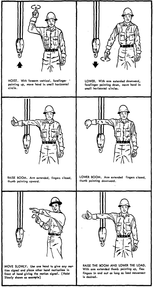
Fig. 1. Standard Hand Signals for Controlling Derricks.
17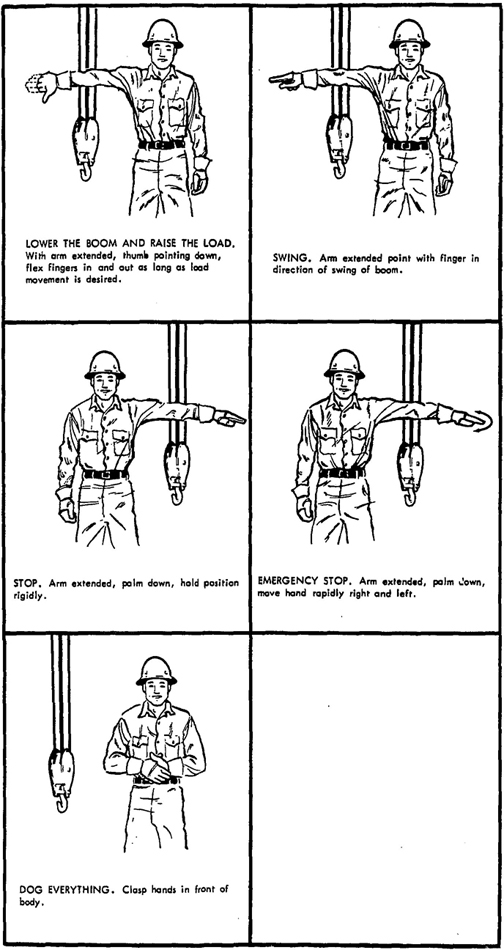
Fig. 1. Standard Hand Signals for Controlling Derricks (Continued).
18 19| Aerial Passenger Tramways | B77.1 – 1960 (1966 Addendum) |
| Conveyors, Cableways, and Related Equipment | B20.1 – 1957 |
| Cranes, Derricks, Hoists, Jacks and Slings | B30.2 – 1943 |
| Crawler, Locomotive, and Truck Cranes | B30.5 – 1968 |
| Derricks | B30.6 – 1969 |
| Elevators, Dumbwaiters, Escalators, and Moving Walks | A17.1 – 1965 (Addenda) |
| Jacks | B30.1 – 1943 (R. 1952) |
| Manlifts | A90.1 – 1969 |
| Mechanical Power Transmission Apparatus | B15.1 – 1953 (R.1958) |
| Mechanized Parking Garage Equipment | A113.1 – 1964 |
| Overhead and Gantry Cranes | B30.2.0 – 1967 |
| Powered Industrial Trucks | B56.1 – 1969 |
| Practice for Inspection of Elevators | A17.2 – 1960 (1965 Addendum) |
Binders for holding Standards are available.
A complete list of Standards published by The American Society of Mechanical Engineers is obtainable upon request.
20