
In order to promote public education and public safety, equal justice for all, a better informed citizenry, the rule of law, world trade and world peace, this legal document is hereby made available on a noncommercial basis, as it is the right of all humans to know and speak the laws that govern them.
ANSI A14.1-1990
American National Standard
for ladders —
portable wood —
safety requirements

ANSI A14.1-1990
American National Standard
for ladders—
portable wood —
safety requirements
| Approved by the A14 Committee during its meeting of September 25, 1992 |
Administrative Co-Secretariat: American Society of Safety Engineers Co-Secretariat: American Ladder Institute |
The INTERPRETATION below represents the committee's view of understanding properly the use of labels/markings in the appendices of this standard.
Preface
Over the years there have been a number of interpretations of various requirements within the A14 Ladder Standards. One which keeps reappearing and has required periodic revisiting is the Labeling/Marking requirements as these relate to the illustrations of more detailed and apparently specific labels/markings in the appendix following Appendix B. To clarify this issue as definitively as possible the following interpretation, reviewed and approved by the A14 Standards Committee, is provided:
Interpretation
While the requirements in the body of the Portable Ladder Standards for labels/marking are keyed to specifically numbered markings, the referred to labels/markings are illustrations only and not intended to be exact renditions of the labels/markings placed on portable ladders. As illustrations the labels/markings, except for technical information in the text, are not required to be exact duplications of those following Appendix B. The graphics of the labels/markings including figures of users, arrows pointing out locations or direction, formatting text with the [Illegible Text Omitted on Page D] of numbers or alphabet or both, and style of expression need not be followed exactly but rather is left to the discretion of the developer of the label/marking or as ordered by a label/marking buyer. Such text or verbiage can be added to or presented more cogently as long as the broad general intent of the label/marking is achieved without changing the basic technical information thus meeting the requirements of the standard for label/marking.
Underscoring the above position is the description of labels/markings as illustrations. Use of the word illustration has been specifically chosen, based upon its meaning, which is defined as an example and explanation. Coupled with this definition — and lending emphasis to it — is the placement of the label/marking illustrations in the appendix since appendices are not part of the standard but explanations and elaborations of the standard and its applicable requirements. In the traditional structuring and development of standards the use of the appendix was also specifically chosen as a recognized means of stating through illustration and explanation how requirements of the standard can be implemented. The use of labels/markings appendix and the illustrations contained therein is construed in the broadest sense as offering designers or buyers general guidance, rather than dictating exact duplication, in creating signs or labels/markings for portable ladders.
DERRATA SHEET
(A14.1 - 1990)
9/19/91
FOREWORD — 2nd Page —3rd Paragraph
Three (3) sentences are added to the end of the paragraph as follows:
While the effective date is 90 days from approval of the standard, actual determination is based upon publication of the availability of the standard, which appeared in the August 10, 1991 issue of the ANSI Reporter. The aforementioned date would make November 10, 1991 the effective date. However, inventories and stocks of labels/markings warrant an additional 90 days for reasonable usage of existing stock.
FOREWORD — 2nd Page — 4th Paragraph
This paragraph becomes the 5th paragraph for the following new 4th paragraph:
An additional issue which has arisen is the requirement for the use of unwaxed vinyl tile as a testing surface. Recent experience and evidence indicate problems in the use of this material which requires suspension of the use of these provisions in the standard. At a recent A14 Committee meeting (9/19/91), the Committee appointed a task force to research a more appropriate material.
PAGE 37 — Top Center of Page
Delete old Table 18 and replace with the following which corrects only the heading or title of the test to Bottom Slip Test.
| Duty Rating and Type | Test Weight on 3rd Highest Fly Rung (pounds) |
Horizontal Pulling Force (pounds) |
|---|---|---|
| Extra heavy duty - Type IA | 300 | 50 |
| Heavy duty - Type I | 250 | 50 |
| Medium duty - Type II | 225 | 50 |
| Light duty - Type III | 200 | 50 |
ANSI®
A14.1 1990
Revision of
ANSI A14.1 1982
Administrative Co-Secretariat
American Society of Safety Engineers
Co-Secretarial
American Ladder Institute
Approved November 16, 1990
American National Standards Institute, Inc
An American National Standard implies a consensus of those substantially concerned with its scope and provisions. An American National Standard is intended as a guide to aid the manufacturer, the consumer, and the general public. The existence of an American National Standard does not in any respect preclude anyone, whether they have approved the standard or not, from manufacturing, marketing, purchasing, or using products, processes, or procedures not conforming to the standard. American National Standards are subject to periodic review and users are cautioned to obtain the latest editions.
The American National Standards Institute does not develop standards and will in no circumstances give an interpretation of any American National Standard. Moreover, no persons shall have the right or authority to issue an interpretation of an American National Standard in the name of the American National Standards Institute.
CAUTION NOTICE: This American National Standard may be revised or withdrawn at any time. The procedures of the American National Standards Institute require that action be taken to reaffirm, revise, or withdraw this standard no later than five years from the date of publication. Purchasers of American National Standards may receive current information on all standards by calling or writing the American National Standards Institute.
Published by
American Society of Safety Engineers
1800 East Oakton Street, Des Plaines, Illinois 60018-2187
Copyright 1990 by American National Standards Institute, Inc.
All rights reserved.
No part of this publication may be reproduced
in any form, in an electronic retrieval system or
otherwise, without the prior written permission
of the publisher.
Printed in the United States of America
2(This Foreword is not a part of American National Standard A 14.1-1990.)
This standard is a revision of American National Standard Safety Requirements for Portable Wood Ladders, ANSI A14.1-1982. It is one of a series of five standards prepared under the supervision of American National Standards Committee on Safety in the Construction. Care and Use of Ladders, A14. All five standards have been developed by subcommittees reporting to American National Standards Committee A14. The subcommittees are: A14-1, Portable Wood Ladders; A 14-2, Portable Metal Ladders; A 14-3. Fixed Ladders; A 14-4, Job-Made Ladders; and A 14-5, Portable Reinforced Plastic Ladders.
All five standards, with the exception of A 14-7 1990, Mobile Ladder Stands, derive from the original American National Standard Safety Code for Construction, Care and Use of Ladders. A14, which was first approved in 1923. Revisions were approved in 1935, 1948, and 1952.
The earlier editions contained some treatment of metal and fixed ladders. Requirements for these types of ladders were removed from the 1948 revision because rapid development in the metal ladder field warranted special consideration and treatment of metal ladders and fixed ladders (usually metal) in separate standards. In 1948, the code was revised and its title and designation changed to American National Standard Code for Wood Ladders, A 14.1. In 1952. it was again revised and retitled American National Standard Safety Code for Portable Wood Ladders. It was further revised in 1959, 1968, 1975, 1980, and 1982.
Responding to a Consumer Product Safety Commission challenge in August 1975, the A 14 Committee mounted a three-prong attack to upgrade the portable ladder standards within the consensus framework of developing standards. Three Task Forces — Anthropometric, Testing, and Labeling — were established in October 1975.
Without question the most massive and technically difficult task, which included a significant amount of human-factors work, was carried out by the Testing Task Force. Over 100 Known ladder experts were solicited to join this task force and provide their technical expertise. The work involved 50 meetings, over 400 test documents, and the use of numerous test ladders over a period of nearly two years. The cost of the project has been conservatively estimated at over $300,000.
At the August 11, 1977, joint meeting of the Testing Task Force and the A 14 Advisory Committee 23, procedures were presented. These procedures, with an accompanying rationale based upon statistical and human-factors data, were distributed to the three portable-ladder subcommittees for review and incorporation into the standards. Recommendations for nomenclature and for care and use of ladders, as well as the Ladder Use Survey Form and Bi-Level Fall Victim Report Form that have been included in the Appendixes, had been previously balloted in order that this more technical material from the Testing Task Force receive the full attention of the three subcommittees.
Test procedures were developed for three different applications, namely, design verification, quality control, and in-service testing. Design verification tests would generally be conducted on a one-time basis during the original design development of the product and would usually be destructive tests. Quality control tests would be conducted by the manufacturer on an on-going basis; some of the tests would be destructive and some would be nondestructive. In-service tests would be conducted by the user or a periodic basis and would be nondestructive in nature.
The A 14 Committee adopted June 4, 1982*, as the effective date of ANSI A 14, 1-1981. This was to allow the manufacturers the necessary lead time to evaluate their products for conformance to the 1981 edition of the three portable-ladder standards, to redesign and test
*The original effective date was March 4, 1982
3their products where applicable, to design and build the required manufacturing tooling and machinery, and to convert their manufacturing operations to produce the revised products.
In 1981, experience by some of the manufacturers indicated that the inclined load test was not practical when applied to all available lengths of extension ladders. Also, recommendations were received for clarifications in test procedure descriptions.
In the course of resolving these questions, evidence was produced to warranty modifications in the label test requirements. As a result, it became necessary to postpone the effective date of these standards from June 4, 1982, to October 4, 1982, to allow investigations which brought about needed changes in label test specifications.
In this current revision several issues which arose since the last revision are addressed. Most notable is the label/marking section where improved graphics were developed as well as new labels.
Suggestions for improvements of this standard will be welcomed. They should be sent to the American Society of Safety Engineers, 1800 E. Oakton St., Des Plaines, III. 60018.
The standard was processed and approved for submittal to ANSI by American National Standards Committee on Safety in the Construction, Care, and Use of Ladders, A 14. Committee approval of the standard does not necessarily imply that all the committee members voted for its approval. At the time it approved this standards, the A 14 Committee had the following members:
Lewis W. Berger, Chairman
Thomas F. Bresnahan, Secretary
| Organization Represented | Name of Representative |
|---|---|
| The Aluminum Association | Robert I. Werner Peter Pollak (Alt) |
| American Institute of Architects | Robert H. Lee |
| American Insurance Association | David P. Winger |
| Alliance of American Insurers | Harry Winchell |
| American Ladder Institute | Alan Kline Robert I. Werner (Alt) |
| Associated General Contractors of America, Inc | Vacant |
| Association of American Railroads | T.M. Hatchard |
| Canadian Standards Association | Robert Reid |
| Edison Electric Institute | David C. Norman Matthew Mingoia (Alt) |
| Exchange Carriers Standards Association | Robert A. Naser Jonathan L. Shaw (Alt) O. J. Gusella |
| Industrial Safety Equipment Association | Allen Neustater Frank E. Wilcher, Jr. (Alt) |
| International Brotherhood of Electrical Workers | Manuel A. Mederos |
| International Brotherhood of Painters & Allied Trades | George J. Jones |
| International Union of Bricklayers & Allied Craftsmen | Albert R. Couillard |
| Metal Ladder Manufacturers Association | Richard L. Werner Jerrold F. Hilton (Alt) Richard Sulecki (Alt) |
| Motor Vehicle Manufacturers Association | Michael Shust Kenneth E. Lauck (Alt) 4 |
| National Association of Architectural Metal Manufacturers | Philip B. Neilson Robert J. Lyons (Alt) |
| National Association of Government Labor Officials | Kenneth J. Zellar John Molovich (Alt) |
| National Fire Protection Association | Samuel C. Cramer Ronald Bennett (Alt) |
| National Retail Federation | Joseph B. Siegel |
| Steel Plate Fabricators Association | Ward Gill Thurmond Yost (Alt) |
| Underwriters' Laboratories | Edward Killoren William R. Hooper (Alt) |
| U.S. Consumer Product Safety Commission | Colin B. Church* Jos. Fandey (Alt)* |
| U.S. Dept. of Agriculture | Vacant |
| U.S. Dept. of the Army, Corps of Engineers | Jerry Haskins |
| U.S. Dept of Labor OSHA | Terence Smith Gilbert Esparza (Alt) |
| ANSI Z133.1 Committee | Robert Felix |
| Independent Specialists | Donald Bloswick John E. Johnson Harold W. Stillman, Jr. |
| *Nonvoting advisory member. | |
Subcommittee A 14-1 on Portable Wood Ladders, which developed this standard, had the following members:
| Robert A. Naser, Chairman | H. W. Buschman J. F. Daly R. G. Howland E. W. Killoren G. H. Kyanka R. F. Nissly J. L. Shaw H. W. Stillman, Jr. C. R. Wallick, Jr. |
| SECTION | PAGE | |||
|---|---|---|---|---|
| 1. | Scope and Purpose | 9 | ||
| 1.1 | Scope | 9 | ||
| 1.2 | Purpose | 9 | ||
| 2. | General | 9 | ||
| 2.1 | Rationale | 9 | ||
| 2.2 | Application | 9 | ||
| 2.3 | Interpretation | 9 | ||
| 2.4 | Mandatory and Advisory Provisions | 9 | ||
| 2.5 | Equivalent | 10 | ||
| 2.6 | Effective Date | 10 | ||
| 3. | Related Standards | 10 | ||
| 4. | Definitions and Nomenclature | 10 | ||
| 5. | Materials | 12 | ||
| 5.1 | Requirements for Wood Parts | 12 | ||
| 5.2 | Classification of Species of Wood | 14 | ||
| 5.3 | Hardware | 14 | ||
| 5.4 | Fasteners | 14 | ||
| 5.5 | Alternate Materials | 14 | ||
| 6. | Construction Requirements | 14 | ||
| 6.1 | Basis of Requirements | 14 | ||
| 6.2 | Portable Stepladders | 15 | ||
| 6.3 | Portable Rung Ladders | 22 | ||
| 6.4 | Special-Purpose Ladders | 27 | ||
| 6.5 | Step Stools (Ladder Type) | 28 | ||
| 7. | Design Verification Test Requirements | 29 | ||
| 7.1 | General | 29 | ||
| 7.2 | Tests For Single and Extension Ladders | |||
| 7.2.1 | Simulated In-Use Inclined Load Test | 30 | ||
| 7.2.2 | Hardware Test Requirements for Extension Ladders | 30 | ||
| 7.2.3 | Side-Rail Cantilever Dynamic Drop Test for Single and Extension Ladders | 34 | ||
| 7.2.4 | Ladder Section Twist Test for Single and Extension Ladders | 34 | ||
| 7.2.5 | Bottom Slip Test | 37 | ||
| 7.2.6 | Multisection Extending Force Test for Extension Ladders | 37 | ||
| 7.3 | Tests for Stepladders, Platform Ladders, Trestle Ladders Extension Trestle Ladders, and Step Stools | 37 | ||
| 7.3.1 | Compression Test | 37 | ||
| 7.3.2 | Bucket Shelf Test for Stepladders | 37 | ||
| 7.3.3 | Front Stability Test for Stepladders, Platform Ladders, Trestle Ladders, Extension Trestle Ladders, and Step Stools | 37 | ||
| 7.3.4 | Side Stability Test for Stepladders, Platform Ladders, Trestle Ladders, Extension Trestle Ladders, and Step Stools | 40 | ||
| 7.3.5 | Rear Stability Test for Stepladders, Platform Ladders, Trestle Ladders, Extension Trestle Ladders, and Step Stools | 40 6 | ||
| 7.3.6 | Torsional Stability Test for Stepladders, Platform Ladders, Trestle Ladders, Extension Trestle Ladders, and Step Stool | 40 | ||
| 7.3.7 | Racking Test for Stepladders, Platform Ladders, Trestle Ladders, Extension Trestle Ladders | 44 | ||
| 7.3.8 | Front Rail and Back Leg Dynamic Drop Test for Stepladders, Platform Ladders, Trestle Ladders, Extension Trestle Ladders, and Step Stools | 44 | ||
| 7.3.9 | Rail Torsion and Spreader Test for Stepladders, Platform Ladders, Trestle Ladders, and Extension Trestle Ladders | 44 | ||
| 7.3.10 | Stepladder Slip Test | 44 | ||
| 7.4 | Labeling Tests | 45 | ||
| 8. | Selection, Care, and Use | 46 | ||
| 8.1 | General | 46 | ||
| 8.2 | Selection | 46 | ||
| 8.3 | Rules for Ladder Use | 48 | ||
| 8.4 | Care | 50 | ||
| 9. | Labeling/Marking Requirements | 51 | ||
| 9.1 | Primary Hazard “Danger” and “Caution” Markings | 51 | ||
| 9.2 | Product Data Information Markings | 52 | ||
| 10. | Revision of American National Standards Referred to in This Document | 53 | ||
| Tables | ||||
| Table 1 | Classification of Various Species of Wood Acceptable for Use in Ladders | 16 | ||
| Table 2 | Minimum Dimensions for Type-I and-IA Stepladders | 19 | ||
| Table 3 | Minimum Dimensions for Type-II Stepladders | 20 | ||
| Table 4 | Minimum Dimensions for Type-III Stepladders | 21 | ||
| Table 5 | Minimum Dimensions of Side Rails for Single Ladders | 23 | ||
| Table 6 | Minimum Dimensions of Side Rails for Two-Section Extension Ladders | 24 | ||
| Table 7 | Minimum Overlap for Two-Section Extension Ladders | 25 | ||
| Table 8 | Minimum Distance between Points of Bearing for Two-Section Extension Ladder | 25 | ||
| Table 9 | Guide Iron Dimensions for Extension Ladders | 25 | ||
| Table 10 | Minimum Dimensions of Side Rails for Sectional Ladders | 26 | ||
| Table 11 | Minimum Dimensions of Side Rails for Trestle Ladders or Base Sections of Extension Trestle Ladders | 27 | ||
| Table 12 | Minimum Dimensions of Side Rails for Extension Sections of Extension Trestle Ladders | 27 | ||
| Table 13 | Required Extension Trestle Ladder Overlap | 27 | ||
| Table 14 | Minimum Dimensions of Side Rails and Rungs for Masons’ Ladders | 28 | ||
| Table 15 | Single and Extension-Ladder Inclined Load Test | 30 | ||
| Table 16 | Hardware Tests | 32 | ||
| Table 17 | Ladder Section Twist Test | 36 | ||
| Table 18 | Bottom Slip Test | 37 | ||
| Table 19 | Stability Test Loads | 39 | ||
| Table 20 | Maximum Allowable Racking Deflection | 43 | ||
| Table 21 | Rail Torsion Test | 44 | ||
| Table 22 | Summary of Significant Accident Causes | 47 | ||
| Table 23 | Ladder Size, Working Length, and Height | 48 7 | ||
| Figures | ||||
| Fig. 1 | Inclined Load Test | 30 | ||
| Fig. 2 | Cyclic Rung Lock Test Arrangement | 31 | ||
| Fig. 3 | Rung Lock Testing Cycle | 32 | ||
| Fig. 4 | Single Lock Load Test | 33 | ||
| Fig. 5 | Standard Loading Block | 33 | ||
| Fig. 6 | Lock Tip Load Test | 34 | ||
| Fig. 7 | Side-Rail Cantilever Dynamic Drop Test | 35 | ||
| Fig. 8 | Single or Extension-Ladder Twist Test | 35 | ||
| Fig. 9 | Bottom Slip Test | 36 | ||
| Fig. 10 | Compression Test | 38 | ||
| Fig. 11 | Front, Side, and Rear Stability Test | 39 | ||
| Fig. 12 | Torsional Stability and Rail Torsion and Spreader Tests | 41 | ||
| Fig. 13 | Racking Test | 42 | ||
| Fig. 14 | Dynamic Drop Test | 43 | ||
| Fig. 15 | Stepladder Slip Test | 45 | ||
| Appendixes | ||||
| Appendix A | Format of Design and Color for Primary Hazard Danger and Caution Labels/Markings | 54 | ||
| Appendix B | Format of Design and Color for the Safety First and Notice Labels/Markings | 55 | ||
| Markings | ||||
| Marking No. 00 - All Ladders | 56 | |||
| Marking No. 1, 2 and 3 - Step Ladders | 57 | |||
| Marking No. 4 - Step Ladders | 58 | |||
| Marking No. 5, 6 and 7 - Extension Ladders | 58 | |||
| Marking No. 8 and 9 - Extension Ladders | 59 | |||
| Marking No. 10 - Extension Ladders | 60 | |||
| Marking No. 11 and 12 - Step Stools | 60 | |||
| Marking No. 13 - Trestle Ladders | 61 | |||
| Marking No. 14 - Extension Trestle Ladders | 61 | |||
| Marking No. 15 - Platform Ladders | 62 | |||
| Marking No. 16 - All Ladders | 62 | |||
| Appendix C | Data Gathering Forms | 63 | ||
American National Standard
for Ladders —
Portable Wood —
Safety Requirements
1.1 Scope. This standard prescribes rules and established minimum requirements for the construction, testing, care, and use of the common types of portable wood ladders described herein in order to ensure safety under normal conditions of usage. It does not cover step stools (furniture type), except ladder-type step stools (see 6.4.4 for other exceptions), nor does it cover ladder accessories, including, but not limited to, ladder shoes, ladder levelers, ladder stabilizers or stand-off devices, ladder jacks, or ladder straps and hooks, that may be installed on or used in conjunction with ladders.
These requirements are also intended to prescribe rules and minimum criteria for labeling/marking of the kinds of portable ladders cited in this standard but exclusive of furniture type step stools and special purpose ladders. These labeling/marking requirements do not apply to those situations where user's training, supervision, or documented safety procedures would duplicate, exceed or be in conflict with the labeling/marking requirements.
1.2 Purpose. The purpose of this standard is to provide reasonable safety for life, limb, and property. In order to develop an effective safety program, the standard should also serve as a basis for purchase requirements and for instruction in personnel training and in the preparation of motivational/instructional material, such as safety practices, manuals, posters, and the like. This standard is also intended to provide the manufacturer, purchaser, and user of wood ladders with a set of specifications and requirements against which a ladder may be compared.
It is not the purpose of this standard to specify all the details of construction of portable wood ladders. The limitations imposed are for the purpose of providing adequate general requirements and testing methods needed for consistency.
2.1 Rationale. A rationale has been developed covering the specifications and performance requirements of this standard.1
2.2 Application. This standard is intended for voluntary use by establishments that use or manufacture ladders. It is also designed to serve as a guide to federal and state authorities or other regulatory bodies in the formulation of laws or regulations.
The methods employed to ensure compliance with this standard shall be determined by the proper regulatory or administrative authority.
2.3 Interpretation. To secure uniform application of this standard, it is recommended that suggestions involving changes in the requirements or disputes over their interpretation be referred to the following organization.
American Society of Safety Engineers, 1800 E. Oakton St., Des Plaines, Ill, 60018
In view of the different kinds of ladders and the many different conditions under which they are used, this standard should be liberally construed. In cases of practical difficulty or under special-service conditions, it is expected that the administrative authority will grant exceptions to the literal requirements of this standard or will permit the use of alternative designs or features, but only if equivalent safety is thereby secured.
2.4 Mandatory and Advisory Provisions. The world “shall” is to be understood as denoting a mandatory requirement. The word “should” is to be understood as denoting a recommendation.
1 The rationale is on file with the co-secretarial.
92.5 Equivalent. The word “equivalent” in this standard means a construction, connection, or material providing equal performance.
2.6 Effective Date. The requirements of this standard shall become effective 90 days after the revised A14.1 standard is approved by ANSI.
This standard is intended for use in conjunction with the following American National Standards or latest revision (See section 10):
American National Standard Safety Requirements for Scaffolding, ANSI A10.8-1988
American National Standard for Ladders — Portable Metal — Safety Requirements, ANSI A14.2-1990
American National Standard for Ladders — Portable Reinforced Plastic — Safety Requirements, ANSI A14.5-1982
American National Standard Nomenclature of Domestic Hardwoods and Softwoods, ANSI/ASTIM D1165-80
American National Standard Methods for Establishing Clear-Wood Strength Values, ANSI/ASTIM D2555-88
angle of inclination. The preferred pitch for portable non-self-supporting ladders.
back leg (rear rail). The support members of a self-supporting portable ladder back section. The back legs are joined by rungs, bars, rear braces, or other bracing to form the back section.
Combination ladder. A portable ladder capable of being used either as a stepladder or as a single or extension ladder. It may also be capable of being used as a trestle ladder or a stairwell ladder. Its components may be used as single ladders.
double front ladder. A self-supporting portable ladder, non-adjustable in length with flat steps front and back that can be climbed on either side by one person at a time.
duty rating. The combination of factors, including, but not limited to, ladder type and design features which imply service capability.
extension ladder. A non-self-supporting portable ladder, adjustable in length. It consists of two or more sections traveling in guides or brackets or the equivalent and so arranged as to permit length adjustment.
extension trestle ladder. A self-supporting portable ladder, adjustable in length, consisting of a trestle ladder base and a vertically adjustable extension section with a suitable means for locking the ladders together.
highest standing level. The vertical distance, expressed in feet and inches, from the uppermost step or rung the climber is advised to use to the horizontal plane of the ladder base support, with the portable in the preferred climbing position.
inside clear width. The distance between the inside flanges of the siderails of a ladder.
ladder. A device incorporating or employing steps or rungs on which a person may step to ascend or descend.
ladder foot, shoe1, or skid-resistant bearing surface. That component of ladder support that is in contact with the lower supporting surface.
ladder type. The designation that identifies the working load.
marking. Any sign, label, stencil, or plate of a primary hazard or informational character, or both, affixed, painted, burned, stamped, or embossed on the ladder surface. (For examples, see Appendixes A and B.)
maximum extended length or maximum working length. The total length of the extension ladder when the middle or intermediate and top or fly sections are fully extended (maintaining the required overlap).
nail. A steel nail, unless otherwise designated.
permanent deformation (set). That deformation remaining in any part of a ladder after all loads have been removed.
pitch. The included (acute) angle between the horizontal and the ladder, which is measured on the side of the ladder opposite the climbing side. It is usually expressed as the ratio H/L which is the horizontal distance H from the base of the ladder to the supporting surface divided by the working length L of the ladder.
platform. A landing surface that is used as a working or standing location.
1 An optional accessory.
10platform ladder. A self-supporting portable ladder of fixed size with a platform provided at the intended highest standing level.
portable ladder. A ladder that can readily be moved or carried, usually consisting of side rails joined at intervals by steps, rungs, or rear braces.
rail. The side members joined at intervals by either rungs or steps.
rear braces. Crosspieces or diagonals (in the back section of a self-supporting ladder) not intended for climbing, which may be spaced at any interval.
rungs or steps. Ladder crosspieces that are intended for use by a person in ascending or descending.
scaffold. A temporary elevated platform and its supporting structure used for supporting worker(s) or materials or both.
section
(1) bottom or base section. The lowest section of a non-self-supporting portable ladder.
(2) top or fly section. The uppermost section of a non-self-supporting portable ladder.
(3) middle or intermediate section. The section between the top (fly) and bottom (base) sections of a non-self supporting portable ladder.
sectional ladder. A non-self-supporting portable ladder, nonadjustable in length, consisting of two or more sections, so constructed that the sections may be combined to function as a single ladder.
single ladder. A non-self-supporting portable ladder, nonadjustable in length, consisting of one section.
size. The quantitative description of the length of the ladder. Methods of defining size are presented in the individual standards.
special-purpose ladder. A portable ladder that is either an experimentally designed ladder or a modification or assemblance of A14 approved requirements for design.
stand-off. A means by which a ladder may be erected at some horizontal distance away from its upper support point.
stepladder. A self-supporting portable ladder, non-adjustable in length, with flat steps and a hinged back.
step stool (ladder type). A self-supporting, foldable, portable ladder, nonadjustable in length, 32 inches or less in overall size, with flat steps and without a pail shelf, designed so that the ladder top cap as well as all steps can be climbed on. The side rails may continue above the top cap.
step surfaces. The clear portion of steps or rungs on which a person may step while ascending or descending a ladder.
test failure. Damage or visible weakening of the ladder structure or a component, except where otherwise defined by the test protocol.
test load. The applied load used to demonstrate compliance with a performance test requirement.
top cap. The uppermost horizontal member of a portable stepladder.
top step. The first step below the top cap of a portable stepladder. Where a ladder is constructed without a top cap, the top step is the first step below the top of the rails.
trestle ladder. A self-supporting portable ladder, non-adjustable in length, consisting of two sections intended for climbing on both sides simultaneously, with rungs or bars for climbing, hinged at the top to form angles with the base.
ultimate failure. The collapse of the ladder structure or, where applicable, a component thereof.
unwaxed vinyl file. In this standard shall be the Official Vinyl Composition Tile (OVCT) available from the Chemical Specialties Manufacturers Association, 1001 Connecticut Ave., Washington, DC 20036.
visual damage. Damage evident by visual inspection.
visual inspection. Inspection by the eye without recourse to any optical devices except prescription eyeglasses.
wood characteristics. Distinguishing features, the extent and number of which determine the quality of a piece of wood.
wood irregularities. Natural characteristics in or on the wood that may lower its durability, strength, or utility.
(1) bark pocket. An opening between annual growth rings that contain bark. Bark pockets appear as dark streaks on radial surfaces and as rounded areas on tangential surfaces.
(2) check. A separation of the wood along the fiber direction that usually extends across the rings of
11annual growth, commonly resulting from stresses set up in the wood during seasoning.
(3) compression failure. A deformation (buckling) of the fibers due to excessive compression along the grain. This deformation may appear as a wrinkle across the surface. In some cases, compression failures may be present but not visible as wrinkles; in such cases they are often indicated by “fiber breakage” on end grain surfaces.
(4) compression wood. An aberrant (abnormal) and highly variable type of wood structure occurring in softwood species.
(5) cross grain (slope of grain). A deviation of the fiber direction from a line parallel to the sides of the piece. Cross grain may be diagonal or spiral, or both.
(6) decay. The disintegration of wood due to the action of wood-destroying fungi; also known as dote and rot.
(7) knot. A portion of a branch or limb, embedded in the tree and cut through in the process of lumber manufacture. It is classified according to sizes, quality, occurrence, and location in the cross section of a piece. The size of the knot is determined by its average diameter on the surface of the piece.
(8) low-density wood. Wood that is exceptionally light in weight and usually deficient in strength properties for the species. In softwood species. low density is frequently indicated by exceptionally wide, or sometimes by extremely narrow, rings, and generally a low proportional of latewood. On the other hand. low-density hardwood, at least in ring-porous species, is most commonly indicated by excessively narrow annual rings in which the earlywood portion predominates.
(9) pitch pocket. An opening extending parallel to the annual growth rings that contains, or that has contained, either solid or liquid pitch.
(10) shake. A separation along the grain, occurring most often between the rings of annual growth.
(11) split. A separation of the wood parallel to the fiber direction due to tearing apart of the wood fibers, normally caused by external forces.
(12) wane. Bark, or lack of wood, on the corner of a piece.
working length. The length of a non-self-supporting portable ladder measured along the rails from the base support point of the ladder to the point of bearing at the top.
working load. The maximum applied load, including the weight of the user, materials, and tools, which the ladder is to support for the intended use.
5.1 Requirements for Wood Parts
5.1.1 Requirements Applicable to All Wood Parts
5.1.1.1 General Requirements. All wood parts of the species specified in Table 1 shall be seasoned at the time of manufacture to a moisture content of not more than 15 percent, smoothly machined and dressed on all sides; free from sharp edges and splinters; and sound and free by accepted procedures of visual inspection form shake, wane, compression failures, decay, or other irregularities except as hereinafter provided. Low-density wood shall not be used.
To allow for normal variations in width and thickness which occur in surfacing lumber, on up to 5 percent of the length of a part, the depth and thickness may be undersized a maximum of 1/64″; when measured at a moisture content of 15 percent. Permissible irregularities as provided for in this standard are based on minimum dimensions. When oversized parts are used some deviations from those irregularities may be allowable.
5.1.1.2 Compression Wood. Compression wood is found mostly in softwoods. Compression wood commonly has a density somewhat higher than that of normal wood but have somewhat lower stiffness and tensile strength for their weight. Compression wood has high longitudinal shrinkage that frequently causes warping of long, slender structural members such as ladder rails. This variant type of wood structure, when of a damaging nature, can be readily identified, by competent and conscientious visual examination by its relatively wide annual rings and large proportion of latewood, which is yellow in color and commonly has a dull lifeless appearance, More-over, the yellow latewood merges with early wood of the same annual rings rather than being more sharply delineated as in many softwood species. The extent of compression wood's effects on strength and warping varies with the proportion of compression wood in a cross section. For example, wide streaks of readily identifiable compression wood comprising the larger part of the annual rings in a piece of lumber are associated with more seriously adverse properties than narrow streaks involving only a few annual rings, particularly when the latewood comprises one-third or less of the ring widths in narrow streaks.
5.1.1.3 Cross Grain. Cross grain is limited in terms of its slope, which is defined as the distance along the sides of the piece in which a deviation of the grain of 1 inch occurs. For example, cross grain with a
12slope of 1 in 12 means that in a distance of 12 inches, the grain deviates 1 inch from the edge of the piece. The slope of grain shall be measured over a distance that will ensure that the determination of the general sloper of the grain is not influence by short local deviations.
Location deviations of the grain from the general slope in the piece are usually associated with a knot or other irregularity that may or may not be present in the piece. In addition to the limits on general slope of grain, it is also desirable, in pieces of small cross section such as occur in ladder parts, to limit the occurrence of local deviations, except for those which are associated with otherwise permitted irregularities appearing in the piece.
5.1.1.4 Limited Irregularities. Black streaks in western hemlock shall not be considered an irregularity. However, chambers associated with black streaks, when present in the part, shall be limited as specified for pitch and bark pockets.
5.1.2. Permissible Irregularities in Side Rails and Back Legs
5.1.2.1 Cross Grain. The general slope of the grain in side rails and back legs shall not be steeper than 1 in 12, except for ladders under 10 feet in length and having flat steps for treads, in which the general slope of the grain shall not be steeper than 1 in 10. The slope of the grain in areas of local grain deviation shall be limited as above when occurring on the narrow face or in the outer one-fourth of the width of the wide face. Local areas of grain deviation within the center half of the width of the wide face may be permitted to contain a grain slope as steep as 1 in 8. Local deviations of grain associated with otherwise permissible irregularities shall be permitted.
5.1.2.2. Knots. Knots shall not appear in a narrow face of a side rail or back leg. Knots, if tight and sound and less than 1/2 inch in diameter, shall be permitted on the wide face provided no part of the knot is within 1/2 inch from either edge and knots are not more frequent than one in any three feet of length.
5.1.2.3 Pitch and Bark Pockets. Pitch and bark pockets in side rails and back legs shall be permitted provided that there is not more than one that is 1/8 inch in width, 2 inches in length, and 1/2 inch in depth, or the equivalent of smaller pockets, on the basis of exposed area and depth, per each 3 feet of length.
5.1.2.4 Checks. Checks that are not more than 6 inches in length or 1/2 inches in depth shall be permitted in side rails or back legs.
5.1.2.5 Splits. Splits that are not more than 2 inches in length shall be permitted in side rails and back legs.
5.1.2.6 Compression Wood. Occurrences of compression wood, in relatively small amounts and positively identified by competent and conscientious visual inspection of side rails and back legs, shall be permitted provided that no single streak exceeds 1/2 inch in width and that the aggregate of streaks does not exceed in with one-fourth of the wide face of the side rail. No streak of compression wood shall be allowed on the narrow face of the rail. Borderline forms of compression wood not positively identified by competent and conscientious visual inspection shall be permitted. Those parts containing bow or crook that would interfere with the operation of the ladder shall not be used. No streaks of compression wood shall be within 1/2 inch of the edge of the rail.
5.1.3. Permissible Irregularities in Flat Steps, Rungs, and Other Ladder Parts
5.1.3.1 Cross Grain in Parts Other Than Rungs. The general slope of grain shall not be steeper than 1 in 12 in pieces for ladders 10 feet and greater in length and not steeper than 1 in 10 in pieces for ladders less than 10 feet in length. The slope of the grain in areas of local deviation shall be limited as is the general slope of the grain. For all ladders, cross grain not steeper than 1 in 10 may be permitted in lieu of 1 in 12 provided the size of the part is increased to afford at least 15 percent greater calculated strength than in ladders built to minimum dimensions. Local deviations of grain associated with otherwise permissible irregularities shall be permitted.
5.1.3.2 Cross Grain in Rungs. The general slope of the grain and the slope in areas of local deviation shall not be steeper than 1 in 15. For all ladders, cross grain not steeper than 1 in 12 may be permitted in lieu of 1 in 15 provided the size of the part is increased to afford at least 15 percent greater calculated strength than in ladders built to minimum dimensions. Local deviations of grain associated with otherwise permissible irregularities shall be permitted.
5.1.3.3 Knots. Permissible knots shall be sound and tight. Knots over 1/8 inch in diameter shall not appear in rungs. Knots shall not appear in the narrow faces of flat steps. Knots appearing in the wide faces of flat steps shall not exceed 1/4 inch in diameter. Knots in other ladders parts shall comply with the requirements of 5.1.2.2.
5.1.3.4 Pitch and Bark Pockets. Pitch and bark pockets shall be permitted provided that there is not more than one that is 1/8 inch in width, 2 inches in length, and 1/2 inch in depth, or the equivalent of
13smaller pockets on the basis of exposed area and depth, per each 3 feet of length.
5.1.3.5 Checks. Seasoning checks shall be permitted at the time of manufacture provided that the checks are not more than 6 inches in length or 1/2 inch in depth.
5.1.3.6 Splits. Splits shall be permitted at time of manufacture provided that they are not more than 2 inches in length.
5.1.3.7 Compression Wood. Occurrences of compression wood, positively identified by competent and conscientious visual inspection, shall be permitted provided that no single streak exceeds 1/2 inch in width and that the aggregate of streaks does not exceed in width one-fourth of the wide face. No streak of compression wood shall be allowed on the narrow face. Borderline forms of compression wood not positively identified by competent and conscientious visual inspection shall be permitted. Parts containing bow or crook that would interfere with the operation of the ladder shall not be used.
5.2 Classification of Species of Wood. Table 1 gives a list of native woods, divided into five groups on the basis of their mechanical properties, considered from the view of use for ladder construction.
5.2.1 Side Rails and Flat Steps. All minimum dimensions and specification set forth hereinafter for side rails and flat steps shall be followed, except that wood from species of group E may be substituted for wood from group D when the former is used in sizes that provide equivalent strength. (See Note 6 of Table 1 for suggested methods of size adjustment.)
5.2.2 Rungs. All minimum dimensions and specifications set forth hereinafter for rungs are based on the species of wood listed in group A of Table 1.
5.3 Hardware. Hardware shall be made of aluminum steel, wrought iron, malleable iron, or other material that is adequate in strength for the purpose intended and free from sharp edges and from sharp projections in excess of 1/64 inch. The materials shall be corrosion and weather resistant.
5.4 Fasteners. Fasteners shall be applied in a tight and secure manner and remain so with normal use and care, or be such that they can be field tightened. Rivets shall be peened or set over the hardware or a washer. The washers shall be standard riveting burrs; that is, 3/16 inch diameter rivets shall use a minimum 1/2 inch diameter burr, and 1/4 inch diameter rivets shall use a minimum 5/8 inch diameter burr. The head of the rivet, when used against wood, shall be a wagon box, truss, or similar type head to afford adequate bearing against the wood. Holes drilled in wood parts for fasteners shall not exceed the diameter of the fastener by more than 1/32 inch.
5.5 Alternate Materials. When a wood ladder is manufactured with a part or parts made of some other materials (aluminum or steel steps, top cap, or rungs), or species not herein specified, these parts shall meet the requirements of this and other applicable American National Standards for ladders. A component part made of other wood-base material may be substituted if it has strength, stiffness, durability, performance, and weathering characteristics at least equal to or exceeding the solid lumber component specified in this standard.
6.1 Basis of Requirements
6.1.1 Types of Ladders
6.1.1.1 Type IA. Type IA is an extra-heavy-duty industrial ladder with a 300-pound duty rating. These ladders are for frequent extra-heavy-duty applications, such as industry, utilities, contractors, and the like.
6.1.1.2 Type I. Type I is a heavy-duty industrial ladder with a 250-pound duty rating. These ladders are for applications such as industry, utilities, contractors, and the like.
6.1.1.3 Type II. Type II is a medium-duty commercial ladder with a 225-pound duty rating. It is for applications such as offices, light maintenance, and the like.
6.1.1.4 Type III. Type III is a light-duty household ladder with a 200-pound duty rating. These ladders are for light household use.
6.1.2 General. The dimensions specified hereinafter for wood ladders are the minimum dressed cross-sectional dimensions for the types of ladders herein designated, based on the species of wood specified in 5.2, at a moisture content of 15 percent. The dimensions for side rails are based on a mortise or gain as specified herein for the various types of ladders for step of rung attachments. Where the strength of the side rails or back legs is reduced by a greater mortise or gain than specified, or where it is desired to use for any wood part a cross section either dimension of which is less than specified, the required dimensions may be found as indicated in 6.1.3.
6.1.3 Formula for Determining Dimensions
6.1.3.1 For the side rails of single, extension, and sectional ladders, the proposed section shall develop an actual stress per square inch not greater
14than 2000 pounds for group A and B woods, 1875 pounds for group C woods, 1600 for group D woods, or 1375 pounds for group E woods when computed by the following formula applying to rectangular sections, with a maximum tolerance of 5 percent over these stresses:
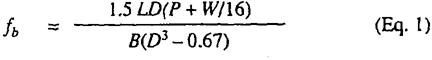
where
p = one-eight of the duty rating, which is the normal component of the applied load to each rail at the center of the ladder, when the foot of the ladder is moved out of the perpendicular by one-quarter of its length. P is 37.5 pounds for type IA, 31.25 pounds for type I, 28.125 pounds for type II, and 25 pounds for type III
fb = stress in extreme fiber in pounds per square inch
W = weight to ladder in pounds (see first footnote of Table 1)
L = maximum working length of ladder in inches (size of ladder less minimum overlap for two-section extension ladder, less 12 inches or 6-inch overhang at each support point)
B = net thickness of each side rail in inches
D = depth of side rail in inches
d = diameter of hole bored for rung (d3 shall be taken as not less than 0.67; this adjustment is for loss of strength in rail from boring of rung hole of 7/8-inch diameter)
Equation 1 is a simplified formula for determining rail sizes.
6.1.3.2 Adjustment of sizes for wood parts of stepladders and other ladder types converted in this standard may be made as follows:
(1) The dimensions throughout this standard for parts having rectangular cross sections generally represent only one of a number of possible combinations of thickness and within that could satisfy the requirements for strength and stiffness. Depending upon the material sizes available, manufacturing practices, and other such variable factors, parts produced by a particular manufacturer may or may not agree exactly with the sizes given subsequently. The rest of 6.1.3.2 provides means for determining equality of load-carrying capacity of parts of different sizes, or for determining the sizes needed to provide equality.
(2) Any changes in dimensions made in accordance with 6.1.3.2(3) shall result in a change in the width-thickness ratio for side rails or back legs not greater than 25 percent from the ratio now specified in this standard for a corresponding ladder unless new dimensions provide a cross section that has a greater modulus (or equivalent strength and safety).
(3) Where both dimensions are different from those specified, the load-carrying capacity in bending of a part will be equal to or greater than that of a part of specified dimensions if the changed section modulus equals or exceeds the specified one; that is:
B2D22 ≥ B1D12 (Eq. 2)
where
B = dimension of the part at right angles to the direction of load (width of a step, thickness of a side rail or back leg)
D = dimension of the part parallel to the direction of load (thickness of a step, width of a side rail or back leg)
B1, D1 = dimensions as specified herein
B2, D2 = dimensions of part being considered
The dimensions to be used in the computation are net dimensions. For example, in the case of a step-ladder side rail, dimension B shall be taken as the gross thickness of the rail minus the depth of the gain for the steps. Where there is a rung hole at the center of depth of a rail, a somewhat more accurate comparison may be made by the use of the adjusted section modulus; that is
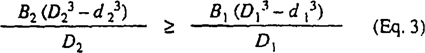
where the symbols have the same meanings as before, and d is the diameter of the hold for the rung tenon. In most instances the difference in results calculated by equations 2 and 3 is slight.
6.2 Portable Stepladders. Stepladders, as hereinafter specified, shall have lengths as follows:
(1) Type IA and Type I — 3 to 20 feet
(2) Type II — 3 to 12 feet
(3) Type III — 3 to 6 feet
The size shall be determined by the overall length measured along the front edge of the size rails, not including the top cap.
6.2.1 General Requirements
6.2.1.1 Slope. Slope is the angle of side rails or back legs with respect to the vertical and is expressed as the horizontal deviation from the vertical per unit length of the member. Stepladders shall be so constructed that when in the open position, the slope of
15| Density (1b/ft3) | |||
|---|---|---|---|
| Species | Average* | Near Minimum |
|
| Group A (Note 2) | |||
| Ash, green | 41 | 33 | |
| Ash, white | 42 | 34 | |
| Beech, American | 44 | 36 | |
| Birch, sweet | 47 | 37 | |
| Birch, yellow | 43 | 35 | |
| Elm, rock† | 45 | 37 | |
| Hickory, bitternut | 49 | 39 | |
| Hickory, mockernut | 50 | 40 | |
| Hickory, nuttneg | 44 | 35 | |
| Hickory, pignut | 53 | 43 | |
| Hickory, shagbark | 50 | 40 | |
| Hickory, shellbark | 49 | 40 | |
| Hickory, water | 49 | 40 | |
| Honeylocust† | 47 | 37 | |
| Locust, black† | 50 | 40 | |
| Hard maple group | |||
| Maple, black | 40 | 32 | |
| Maple, sugar | 44 | 36 | |
| Maples, red | 38 | 30 | |
| Red oak group | |||
| Oak, black | 44 | 35 | |
| Oak, cherry bark | 47 | 37 | |
| Oak, northern red | 44 | 35 | |
| Oak, pin | 45 | 37 | |
| Oak, scarlet | 48 | 38 | |
| Oak, willow | 43 | 35 | |
| White oak group | |||
| Oak, chestnut | 45 | 37 | |
| Oak, live† | 64 | 51 | |
| Oak, post | 47 | 37 | |
| Oak, swamp chestnut | 47 | 37 | |
| Oak, swamp white | 50 | 40 | |
| Oak, white | 47 | 37 | |
| Pecan | 48 | 38 | |
| Tanoak†, ‡ | 45 | 37 | |
| Group B (Note 3) | |||
| Douglas fir§ | |||
| Coast | 34 | 26 | |
| Interior north | 34 | 28 | |
| Interior south | 33 | 26 | |
| Interior west | 35 | 27 | |
| Larch, western | 37 | 30 | |
| Pine, southern | |||
| Pine, loblolly | 36 | 30 | |
| Pine, longleaf | 42 | 34 | |
| Pine, shortleaf | 35 | 29 | |
| Pine, slash | 42 | 34 | |
| Group C (Note 4) | |||
| Softwoods: | |||
| Cedar, Port Orford | 30 | 24 | |
| Hemlock, western | 32 | 24 | |
| Tamarack | 38 | 31 | |
| Hardwoods: | |||
| Cucumbertree | 34 | 27 | |
| Elm, slippery | 38 | 31 | |
| Oak, laurel | 44 | 35 | |
| Oak, overcup | 44 | 35 | |
| Sweeigum | 35 | 29 | |
| Group D (Note 5) | |||
| Softwoods: | |||
| Baldcypress | 33 | 26 | |
| Cedar, Alaska | 32 | 26 | |
| Fir, California red | 27 | 21 | |
| Fir, grand | 26 | 20 | |
| Fir, noble | 28 | 22 | |
| Fir, Pacific silver | 30 | 22 | |
| Fir, white | 28 | 22 | |
| Pine, red (Norway) | 32 | 26 | |
| Pine, southern (minor species) | |||
| Pine, pitch | 36 | 30 | |
| Pine, pond‡ | 39 | 31 | |
| Pine, sand‡ | 35 | 29 | |
| Pine, Virginia | 35 | 29 | |
| Redwood (old-growth)** | 30 | 25 | |
| Spruce, red | 29 | 24 | |
| Spruce, Sitka | 29 | 24 | |
| Spruce, white | 29 | 24 16 | |
| Hardwoods: | |||
| Elm, American | 35 | 29 | |
| Hackberry | 38 | 31 | |
| Magnolia, southern | 35 | 29 | |
| Maple, bigleaf | |||
| (Oregon)† | 34 | 27 | |
| Oak, southern red | 41 | 33 | |
| Group E (Note 6) | |||
| Softwoods: | |||
| Cedar, incense | 26 | 22 | |
| Hemlock, eastern | 30 | 25 | |
| Pine, eastern white | 26 | 22 | |
| Pine, lodgepole | 30 | 25 | |
| Pine, ponderosa | 30 | 25 | |
| Pine, western white | 28 | 23 | |
| Spruce, Engelmann | 25 | 20 | |
| Hardwoods: | |||
| Alder, red | 29 | 24 | |
| Aspen, bigtooth | 27 | 22 | |
| Oak, bur | 47 | 37 | |
| Poplar, yellow | 30 | 24 | |
| Sycamore, American | 35 | 29 | |
| Tupelo, black | 36 | 30 | |
| Tupelo, water | 35 | 29 | |
| NOTES: (1) Species are listed alphabetically within each group. The position of any species within a group bears to relation to its strength or acceptability. With few exceptions, the species names conform with the official common tree names as listed in American National Standard Nomenclature of Domestic Hardwoods and Softwoods, ANSI/ASTM D1165-80. Species names are sometimes preceded by the commercial name for lumber when the commercial name is significantly different or represents a commercial species group. Botanical names for each species are listed in ANSI/ASTM D1165-80. The fiber stress in bending of each species in each group is equal to or greater than the fiber stress for the group. Values were calculated based on data and procedures presented in American National Standard Methods for Establishing Clear-Wood Strength Values, ANSI/ASTM D2555-88. Near-minimum strength values for each species at the 5% exclusion limit were calculated for wood at a moisture content of 15% and divided by 4.1 and 4.5 for softwoods and hardwoods, respectively, to arrive at the allowable fiber stress. Average and near-minimum density values are for wood at 15% moisture content. (2) Group A woods are used principally for rungs. Experience has shown that these species are satisfactory when of the required size and quality. No allowable stress is assigned for rungs. The fiber stress in bending for the species listed here when used for side rails shall not exceed 2000 pounds per square inch. These species may be substituted for group B woods. (3) The fiber stress in bending for the species listed here when used for side rails shall not exceed 2000 pounds per square inch. (4) The fiber stress in bending for the species listed here when used for side rails shall not exceed 1875 pounds per square inch. (5) The fiber stress in bending for the species listed here when used for side rails shall not exceed 1600 pounds per square inch. (6) The fiber stress in bending for the species listed here when used for side rails shall not exceed 1375 pounds per square inch. These species may be substituted for group D woods on the following basis: The dimensions shall be at least 5% greater for each cross-section dimension, or the thickness may remain unchanged, in which case the width shall be at least 7-1/2% greater if used edgewise (as in a rail) or 15% greater if used flatwise (as in a tread). |
|||
| *The formula in 6.1.3 includes the weight of the ladder involved in the calculation. For convenience in estimating ladder weights the average densities of the species listed in this table are given for a moisture content of 15%. Involved also in the weight of an extension ladder are certain items of hardware such as locks, guide irons, and the bolts and rivets attaching these to the ladder. Other items of hardware that are attached at the ends of the ladder, such as safety feet and hooks, do not contribute to the bending of the ladder; their weight, therefore, need not be included. The practice among different manufacturers with respect to hardware varies considerably; no single value of hardware weight, therefore, can be given. For purposes of calculation, a weight in the range of 4 to 8 pounds, with an average of about 6 pounds, may be used. Where it is known that specific items of hardware are to be used, so that their weights may be measured or estimated, the weights so determined should be used. | |||
| †Allowable stresses for this species cannot be calculated from data in American National Standard Methods for Establishing Clear-Wood Strength Values, ANSI/ASTM D2555-88. Adequate strength data are available, however, and the species is accordingly included in this grouping. | |||
| ‡Not listed in American National Standard Nomenclature of Domestic Hardwoods and Softwoods, ANSI/ASTM D1165-80. | |||
| §This species is now graded for structural purposes based on one of the four growth ranges from which it originated. The regional description is given on pages 54-55 of the U.S. Forest Service Research paper FPL 27, “Western Wood Density Survey Report No. 1,” available from U.S. Department of Agriculture, Forest Products Laboratory, P.O. Box 5130, Madison, Wis. 53705. | |||
| **Values for old-growth redwood are significantly higher than for second-growth redwood. See ANSI/ASTM D2555-88. | |||
the front section shall not be less than 3-1/2 inches and the slope of the back section not less than 2 inches for each 12-inch length of side rail or back leg.
6.2.1.2 Step Spacing. The uniform step spacing measured along the rail shall not be more than 12 inches (+1/4 inch, -1 inch). Steps shall be parallel and level within ±2° relative to the lower support surface when the ladder is in position for use.
NOTE: Stepladders with the top step 18 inches below the top cap and the bottom step 6 inches above the base support are permitted as an alternate means of construction, and in this case the top step may be used for stepping purposes. When the top step is 18 inches below the top cap, provision should be made to restrict inadvertent stepping into the opening.
6.2.1.3 Width and Spread. The minimum clear width between the side rails at the top step, inside to inside, shall be 11-1/2 inches. The minimum base width shall be determined by providing an overall increase in the spread of a minimum of 1-1/4 inch per foot from the top step to base, measured along the side rail.
6.2.1.4 Step Attachment. When side rails of minimum thickness are used, steps shall be closely fitted into the grooves in the side rails; the grooves shall be 1/8 inch in depth with a tolerance of ±1/32 inch and shall be firmly secured as hereinafter described. Alternatively, steps shall be closely fitted into metal brackets of an equivalent strength, which in turn shall be firmly secured to the side rails. The depth of groove specified herein may be increased in proportion to the thickness of side rails as provided in 6.2.2.1, 6.2.3.1, and 6.2.4.1.
6.2.1.5 Top Cap. All stepladders shall have a one-piece or multiple-piece top cap with wood or metal brackets or fittings tightly secured to the top and to the side rails or back legs, or both, to allow free swinging of the back section without excessive play or wear at the joints. Rivet spacing shall be no less than 1-1/4 inches. On type-IA and type-I stepladders there shall be a minimum of three 3/16-inch-diameter or two 1/4-inch-diameter rivets, or equivalent fasteners, to attach each metal bracket to each front rail, if metal brackets are used to provide the top hingeing of the back section.
6.2.1.6 Spreader. A metal spreader or locking device of sufficient size and strength to securely hold the front and back sections in the open position shall be a component of each stepladder. The spreader shall have all sharp points covered or removed to protect the user. For the type-III ladder the pail shelf and spreader may be combined in one unit (the so-called shelf-lock ladder). The spreader, or the lower set of a double set of spreaders when used, shall not be more than 6-1/2 feet above the lower support surface. When spreader hooks are used in lieu of the lower spreader, they shall be installed at sufficient heights so that they can be folded downward and secured when the ladder is folded.
6.2.1.7 Length Tolerance. When measured along the front edge of the side rails, all stepladders shall measure within 2 inches of the specified length.
6.2.1.8 Bucket Shelves. When bucket shelves are provided, they shall meet the test requirements of 7.8.2 and shall be so fastened that they can be folded up within the ladder when the ladder is closed. On ladders 8 feet or less in length, the shelf shall be designed so that it must be partially folded before the ladder can be closed, or during the closing of the ladder, the shelf shall fold so that it is at least 35 degrees from horizontal when the ladder is vertical and fully closed.
6.2.1.9 Hardware. All hardware and fittings shall be securely attached by means of rivets, bolts, screws, or equivalent means.
6.2.1.10 Shoes. When shoes or other means are needed to meet the performance requirements of any of the tests in Section 7, they shall be securely bolted, nailed, or riveted, or attached by equivalent methods, with the exception of elastic boot-types that are properly fitted.
6.2.1.11 Step Width. Step width shall be as required in other sections of this standard, but in no case be less than 3 inches.
6.2.2 Type IA and Type I — Industrial Step-ladders
6.2.2.1 Dimensions. The minimum dimensions of the parts of Type-IA and Type-I stepladders shall be as given in Table 2 when these parts are made of group A, B, C, or D woods.
The minimum thickness of the side rails provides for the cutting of a groove 1/8 inch in depth with the tolerance indicated in 6.2.1.4 and shall be increased when grooves of greater depth are used. The minimum thickness of the steps provides for the cutting of tread grooves in the top surface not exceeding 1/8 inch in width and 1/16 inch in depth and a rod-lock groove in the underside of the step not exceeding 9/32 inch in width and 9/32 inch in depth.
NOTE: The upper eleven steps on 14-through 20-foot Type-IA and Type-I stepladders may be dimensioned as those for Type-IA and Type-I 12-foot stepladders.
6.2.2.2 Flat Steps. Steps shall be secured from front-to-back lateral movement with at least two 6d nails (minimum dimensions: 0.0858 inch in diameter and 1-7/8 inches long) at each end, or the equivalent
18| Length 12 Feet and Less | Length 14 and 16 Feet | Length 18 and 20 Feet | ||||
|---|---|---|---|---|---|---|
| Ladder Part | Thickness (inches) |
Depth (inches) |
Thickness (inches) |
Depth (inches) |
Thickness (inches) |
Depth (inches) |
| Type-IA Stepladders | ||||||
| Side rails | 1 | 3-1/4 | 1 | 3-1/2 | 1-1/16 | 3-1/2 |
| Back legs | 1-1/16 | 2-1/4 | 1-1/16 | 2-3/8 | 1-3/8 | 2-3/8 |
| Steps | 3/4 | 3-1/2 | 3/4 | 4-1/4 | 3/4 | 4-1/4 |
| Top Cap | 3/4 | 5-1/2 | 3/4 | 5-1/2 | 3/4 | 5-1/2 |
| Type-I Stepladders | ||||||
| Side rails | 3/4 | 3-1/4 | 3/4 | 3-1/2 | 1-1/16 | 3-1/2 |
| Back legs | 3/4 | 2-1/4 | 3/4 | 2-5/8 | 1-1/16 | 2-1/4 |
| Steps | 3/4 | 3-1/2 | 3/4 | 4 | 3/4 | 4 |
| Top cap | 3/4 | 5-1/2 | 3/4 | 5-1/2 | 3/4 | 5-1/2 |
thereof such as rod-lock construction. When nails are used, they shall be located at least 3/8 inch from the rail edge. Steps less than 30 inches long shall be reinforced by a steel rod not less than 0.160 inch in diameter, with standard commercial tolerances. Steps 30 inches in lengths and longer shall be reinforced by a steel rod not less than 0.180 inch in diameter, with standard commercial tolerances. These rods shall pass through flat metal washers of minimum 18-gage thickness and at least 1-inch diameter or through formed steel washers of 24-gage minimum thickness on each end to prevent them from excessive pressing into the side rails. A truss block shall be fitted between the rod and the center of each step. An alternative construction may be provided by a metal angle brace on each end, firmly secured to the step and the side rails, or by other construction of equivalent strength.
When rod-reinforced construction is used, the end of the rod shall be peened, and the bottom step shall also be provided with a metal angle brace on each side, which shall be securely riveted, or the equivalent, to the bottom step and side rails. In addition, all steps 3-5/8-to 4-1/4 inches wide and 27 inches or more in overall length shall be provided with a metal angle brace at each end, securely riveted to the step and side rail, or shall have construction of equivalent strength. The maximum projection on the leading edge of a step shall not exceed 3/4 inch at the top of the step.
6.2.2.3 Bracing of Back Section. The back section shall be braced by one of the methods outlined in 6.2.2.3.1 and 6.2.2.3.2.
6.2.2.3.1 The back legs shall be braced with 1-1/8 inch diameter dowels made of group A woods (see Table 1), or material of equivalent strength, having 7/8-inch diameter tenons or oval, square or rectangular wood cross pieces of equivalent strength, spaced not more than 24 inches apart. The back legs shall be bored with holes extending either through the legs or to within 1/8 inch of the outside face of the legs, and the size of the hole shall be such as to ensure a tight fit for the cross piece. The minimum length of the tenon shall be 9/16 inch; the shoulder of the cross piece shall be forced firmly against the leg, and the tenon shall be secured in place with a 0.080-inch-diameter nail, or the equivalent thereof, to prevent turning of the cross piece. At a minimum, the length of the fastener shall be sufficient to pass through the tenon and at least 1/8 inch beyond into the back leg.
The back legs shall be braced by a metal angle brace on each side securely riveted to the cross piece and the back legs; one cross piece shall be braced for each 4 feet in length, with braces required only on the bottom cross piece shall be braced with a metal angle brace on each side, and the spacing between the braces shall not be more than 4 feet. Where cross pieces between the back legs are more than 28 inches in length, they shall be provided with center bearing consisting of a wood bar not less than 3/4 × 2 inches in cross section securely nailed to each cross piece, passing through the cross piece, and long enough to include each cross piece longer than 28 inches. Where there is only one such cross piece.
19supported by metal braces, the center bearing is not required.
6.2.2.3.2 The back leg shall be braced with horizontal wood bars made of group A, B, C, or D Woods (see Table 1), not less than 3/4 × 2-1/2 inches in cross section, and spaced not more than 24 inches apart. The ends of the bars shall fit into metal sockets of not less than 24-gage (Manufacturer's Standard) steel, or other material of equivalent strength, or into mortises of not less than 1/8 inch ± 1/32 inch in depth in the back legs. A steel rod not less than 0.160 inch in diameter, with standard commercial tolerances, shall pass through the back legs and the bar, and at each end through flat metal washers at least 1 inch in diameter and of minimum 20-gage thickness or formed steel washers of 24-gage minimum thickness to prevent the rod from excessively pressing into the back legs. The back legs shall also be braced by a metal angle brace on each side, securely riveted to the bar and to the legs; one bar shall be so braced for at least each 4 feet of length or fraction thereof, with braces required only on bottom bars for ladders that are 4 feet or shorter. Metal sockets, when used, shall be attached to the back legs by rivets, by means of a rod running through the socket, or by equivalent means.
6.2.2.4 Antisplit Devices. Where a separate hinge is not used, the back legs shall be reinforced by a rivet through the depth of the leg above the top hinge or pivot point, by other metal plates or collars at the hinge point, or by other means suitable for preventing splitting of the back leg from the hinge pin to the top.
6.2.3 Type II — Commercial Stepladder
6.2.3.1 Dimensions. The minimum dimensions of the parts of type-II stepladders shall be as given in Table 3 when these parts are made of group A, B, C, or D woods.
The minimum thickness of the side rails provides for the cutting of a groove 1/8 inch in depth with the tolerance indicated in 6.2.1.4 and shall be increased when grooves of greater depth are used. The minimum thickness of the steps provides for the cutting of tread grooves in the top surface not exceeding 1/8 inch in width and 1/16 inch in depth and a rod-lock groove in the underside of the step not exceeding 9/32 inch in width and 9/32 inch in depth.
6.2.3.2 Flat Steps. Steps shall be secured from front-to-back lateral movement with at least two 6d nails (minimum dimensions: 0.0858 inch in diameter and 1-7/8 inches long) at each end, or the equivalent thereof such as rod-lock construction. When nails are used, they shall be located at least 3/8 inch from the rail edge. Each step shall be reinforced by a steel rod not less than 0.160 inch in diameter, with standard commercial tolerances, which shall pass through flat metal washers of minimum 20-gage thickness and at least 1 inch diameter or through formed steel washers of 24-gage minimum thickness on each end to prevent the rod from excessively pressing into the side rails.
A truss block shall be fitted between the steel rod and the center of each step. Alternative construction may be provided by a metal angle brace on each end, firmly riveted to the step and side rail, or by other construction of equivalent strength.
Where rod reinforced construction is used, the end of the rod shall be peened, and the bottom step shall also be provided with a metal angle brace on each side, which shall be securely riveted, or the equivalent, to the bottom step and side rails. In addition, all steps 27 inches or more in overall length shall be provided with a metal angle brace at each end, securely riveted to the step and side rails, or shall have construction of equivalent strength. The maximum projection on the leading edge of a step shall not exceed 3/4 inch at the top of the step.
6.2.2.3 Bracing of Back Section. The back section shall be braced by one of the methods given in 6.2.3.3.1 through 6.2.3.3.3.
| Length 3 to 8 Feet | Length 10 Feet | Length 12 Feet | ||||
|---|---|---|---|---|---|---|
| Ladder Part | Thickness (inches) |
Depth (inches) |
Thickness (inches) |
Depth (inches) |
Thickness (inches) |
Depth (inches) |
| Side rails | 3/4 | 2-5/8 | 3/4 | 2-5/8 | 3/4 | 3 |
| Back legs | 3/4 | 1-5/8 | 3/4 | 1-3/4 | 3/4 | 2 |
| Steps | 3/4 | 3-1/4 | 3/4 | 3-1/4 | 3/4 | 3-1/2 |
| Top Cap | 3/4 | 5 | 3/4 | 5 | 3/4 | 5 |
6.2.3.3.1 The back legs shall be braced with cross pieces consisting of ⅞-inch-diameter dowels made of group A woods (see Table 1), or material of equivalent strength, having ⅝-inch-diameter tenons firmly secured in the back legs and spaced not more than 12 inches apart. The back legs shall be bored with holes extending either through the legs or to within ⅛ inch of the outside face of the legs, and the size of the hole shall be such as to ensure a tight fit for the dowel. The minimum length of the tenon shall by 9/16 inch. The shoulder of the dowel shall be forced firmly against the leg, and the tenon shall be secured in place with a 0.080-inch-diameter nail, or the equivalent thereof, to prevent turning of the dowel. At a minimum, the length of the fastener shall be sufficient to pass through the tenon and at least ⅛ inch beyond into the back leg.
A bar connecting two or more of the dowels shall be provided on all ladders of 6-foot length or more. The cross-sectional dimensions of the bar shall be the same as the cross-sectional dimensions of the back legs, and the dowels shall pass through holes at the centerline of the bar. The bar shall be attached at the center of the length of the lower two dowels on a 6-foot ladder and shall extend upward one dowel for each additional 2 feet of length.
6.2.3.3.2 The back legs shall be braced with wood dowels as set forth in 6.2.3.3.1 plus an inverted V bracing of ¾ × 1-½ inch material through which the dowels extend; the length of the V shall extend two-thirds of the way up the back.
6.2.3.3.3 The back legs shall be braced with horizontal wood bars made up of group A, B, C, D, or E woods (see Table 1) not less than ¾ × 2 inches in cross section, the ends of which shall fit into metal sockets of not less than 24-gage (Manufacturer's Standard) steel, or other material of equivalent strength, or into mortises in the back legs not less than ⅛ inch ± 1/32 inch in depth. The bars shall be reinforced by steel rods not less than 0.160 inch in diameter, with standard commercial tolerances, which shall pass through the back legs and the bar, and at each end through flat metal washers at least 1 inch in diameter and 20-gage minimum thickness, or through formed steel washers of 24-gage minimum thickness, to prevent the rods from excessively pressing into the back legs. The spacing of such bars shall not exceed 3 feet, and there shall be at least one bar on 3- and 4-foot ladders, two bars on 5- and 6-foot ladders, three bars on 7- and 8-foot ladders, and four bars on 10- and 12-foot ladders. The bottom bar shall be not more than 18 inches from the bottom of the ladder, and where only one bar is used, it shall be braced by a metal angle brace on each and securely riveted to the bar and the back leg, or by construction of equivalent strength.
6.2.3.4 Antisplit Devices. Where a separate hinge is not used, each back leg shall be reinforced by a rivet through the depth of the leg above the top hinge or pivot point, by metal plates or collars at the hinge point, or by other means suitable for preventing splitting of the back leg from the hinge pin to the top.
6.2.4 Type III—Household Stepladder
6.2.4.1 Dimensions. The minimum dimensions of the parts of the type-III stepladder shall be as given in Table 4 when these parts are made of group A, B, C, or D woods.
The minimum thickness of the side rails provides for the cutting of a groove ⅛ inch in depth with the tolerance indicated in 6.2.1.4 and shall be increased when grooves of greater depth are used. The minimum thickness of the steps provides for the cutting of tread grooves in the top surface not exceeding ⅛ inch in width and 1/16 inch in depth and a rod-lock groove in the underside of the step not exceeding ¼ inch in width and ¼ inch in depth.
6.2.4.2 Flat Steps. Steps shall be secured from front-to-back lateral movement with at least one 6d nail (minimum dimensions: 0.0858 inch in diameter and 1-⅞ inches long) at each end, or the equivalent thereof such as rod-lock construction. When nails are used, they shall be located at least ⅜ inch from the rail edge. Each step shall be reinforced by a steel rod not less than 0.160 inch in diameter, with standard commercial tolerances, which shall pass through flat metal washers of a minimum 20-gage thickness or formed steel washers of 24-gage minimum thickness and at least one inch in diameter on each end to prevent the rod from excessively pressing into the side rails. Alternate construction may be provided by a metal brace at each end securely riveted to the step and side rail, or by other construction of equivalent strength.
Where rod reinforced construction is used, the end of the rod shall be peened, and the bottom step shall be provided further with a metal angle brace on each end
| Ladder Part | Length 3 to 6 Feet | |
|---|---|---|
| Thickness (inches) |
Depth (inches) |
|
| Side rails | ¾ | 2-½ |
| Back legs | ¾ | 1-5/16 |
| Steps | ¾ | 3 |
| Top cap | ¾ | 5 |
which shall be securely riveted, or the equivalent, to the bottom step and side rails. The maximum projection on the leading edge of a step shall not exceed ¾ inch measured at the top of the step.
6.2.4.3 Bracing of Back Section. The back section shall be braced by one of the methods given in 6.2.4.3.1 and 6.2.4.3.2, or by construction of equivalent strength.
6.2.4.3.1 Back legs shall be braced by diagonal slats made of group A, B, C, D, or E woods (see Table 1) not less than ⅜ x 1-15/16 inches, securely fastened to the back legs by screws (minimum length 1 inch), or the equivalent thereof. Diagonal slats shall be joined at the point of intersection with a clinched nail, or the equivalent thereof. Six-foot ladders shall also include a horizontal slat of ⅜ x 1-15/16 inches, located no higher than one-third the length of the back legs from the lower support surface.
6.2.4.3.2 Back legs shall be braced with horizontal wood bars made of group A, B, C, D, or E woods (see Table 1) not less than ⅝ x 1-⅝ inches in cross section, the ends of which shall fit into metal sockets of not less than 24-gage (Manufacturer's Standard) Steel, or other material of equivalent strength, or into mortises in the back legs not less than ⅛ inch ±1/32 inch in depth. The bars shall be reinforced by steel rods not less than 0.160 inch in diameter, with standard commercial tolerances, which shall pass through the back legs and the bar, and at each end through flat metal washers at least 1 inch in diameter and 20-gage minimum thickness or formed steel washers of 24-gage minimum thickness to prevent the rods from excessively pressing into the legs. The spacing of such bars shall not exceed 3 feet, and there shall be at least one bar on 3- or 4-feet two bars on 5- and 6-foot ladders. The bottom bar shall be not more than 18 inches from the bottom of the ladder and where only one bar is used, it shall be braced by a metal angle brace on each end securely riveted to the bar and the back leg or by construction of equivalent strength.
6.3 Portable Rung Ladders. Portable rung ladders as herein specified shall be of four kinds: (1) single ladder, (2) two-section extension ladder, (3) sectional ladder, and (4) trestle and extension trestle ladders.
6.3.1 General Requirements
6.3.1.1 Base. The bottom or lower portion of a ladder may be designed with parallel side rails, with side rails varying uniformly in separation along the length (tapered), or with side rails flaring at the base.
6.3.1.2 Rung Spacing. Rungs shall be parallel, level, and uniformly spaced. The rung spacing shall be on 12-inch ± ¼ centers, except for trestle and extension trestle ladders. (See 6.3.5.7)
6.3.1.3 Rung Joint. All holes for wood rungs shall either extend through the side rails or be bored so as to give at least a ⅞ inch length of bearing to the rung tenon. In through-bored construction, the rungs shall extend so that they are at least flush with the outside rail surface. All holes shall be located on the centerline of the wide face of the side rails and shall be of such size as to ensure a right fit for the rung. The shoulder of the rung shall be forced firmly against the side rails and the tenon secured in place so a to maintain the rung position in the side rail and prevent it from turning. The minimum length of the fastener shall be sufficient to pass completely through the diameter of the tenon and at least ⅛ inch beyond into the side rail. The fastener shall be a common nail of at least 0.080 inch diameter or one of equivalent holding power.
6.3.1.4 Rung Dimensions. Round rungs shall be made of group A woods (see Table 1). The dimensions shall be as follows:
| Rung Length | Minimum Diameter |
| Up to 24 inches | 1-⅛ inches |
| 24-28 inches | 1-3/16 inches |
| Over 28 inches | 1-¼ inches |
A 1-1/8 inch diameter rung may be substituted for a 1-3/16-inch diameter rung if it is reinforced with a steel rod having a minimum diameter of 0.160 inch, rung braces, or center bearing. 1-3/16-inch diameter rungs may be substituted for 1-1/4 inch diameter rungs on the same basis.
All rungs shall have tenons with a minimum diameter of 7/8 inch. Rungs of equivalent strength and bearing may be provided. All rungs more than 28 inches in length between rails shall, in addition, be provided with center bearing or equivalent support.
6.3.1.5 Oval Rungs. Oval rungs or rungs of any other cross section may be used provided they are secured by a nail at each end as described in 6.3.1.3, or the equivalent thereof, and have at least the same strength and bearing as round rungs of the same length.
6.3.1.6 Hardware. All hardware and fittings shall be securely attached by means of rivets, bolts, screws, or equivalent means.
6.3.1.7 Movable Parts. The construction and assembly of movable parts shall operate freely and securely without binding or unnecessary play.
6.3.1.8 Length Tolerance. When measured along the side rails, no rung ladder or section thereof
22shall be more than 3 inches shorter than the specified length.
6.3.1.9 Shoes or Antislip Devices. Shoes or antislip devices are optional equipment. When installed by the manufacturer of the ladder at the request of the user, they shall be securely bolted, nailed, riveted, or attached by equivalent construction to the side rails, with the exception of elastic boot-type shoes that are properly fitted.
6.3.2 Single Ladder
6.3.2.1 Length. Single ladders as hereinafter specified shall be of four types and lengths: (1) Type IA and I shall not exceed 30 feet, (2) Type II shall not exceed 20 feet, and (3) Type III shall not exceed 14 feet. The size shall be determined by the overall length measured along the side rail.
6.3.2.2 Side-Rail Dimensions. The minimum dimensions of the side rails of Type-IA, -I, -II, and -III single ladders shall be not less than those specified in Table 5 when the rails are made of group B, C, or D woods.
6.3.2.3 Reinforced Rails. Smaller side rails will be acceptable in all ladders of this type when the rails are reinforced on the underside by a steel wire, rod, or strap running their entire length and adequately secured thereto. Where such reinforcement is used, the reinforced rails shall be equivalent in strength to the side rails specified in 6.3.2.2 and shall be marked as being electrically conductive.
6.3.2.4 Width. The width between the side rails at the base, inside to inside, shall be at least 11-½ inches for all ladders up to and including 10 feet. Such minimum widths shall be increased at least ¼ inch for each additional 2 feet of length.
6.3.3 Two-Section Extension Ladder
6.3.3.1 Sizes. Two-section extension ladders as hereinafter specified shall be of four types and sizes: (1) Type IA and I shall not exceed 60 feet, (2) Type II shall not exceed 40 feet, and (3) Type III shall not exceed 28 feet. These ladders shall consist of two sections; the top section nearest the climber shall fit within the side rails of the bottom section and be arranged in such a manner that the upper section can be raised and lowered. The size shall be determined by the sum of the lengths of the sections measured along the side rails.
6.3.3.2 Side-Rail Dimensions. The minimum dimensions of the side rails of Type-IA, -I, -II, and -III two-section extension ladders shall be not less than those specified in Table 6 when the rails are made of group B, C, or D woods.
6.3.3.3 Overlap. The minimum dimensions of side rails set forth in Table 6 are based on the maximum
| Length of Ladder (feet) |
Rail Dimensions | |
|---|---|---|
| Thickness (inches) |
Depth (inches) |
|
| Type IA-Group B Woods | ||
| Up to and including 16 | 1-1/16 | 2-½ |
| Over 16, up to and including 20 | 1-1/16 | 2-¾ |
| Over 20, up to and including 30 | 1-5/16 | 3 |
| Type IA-Group C Woods | ||
| Up to and including 16 | 1-1/16 | 2-⅝ |
| Over 16, up to and including 20 | 1-⅛ | 2-¾ |
| Over 20, up to and including 30 | 1-⅜ | 3 |
| Type IA-Group D Woods | ||
| Up to and including 16 | 1-1/16 | 2-¾ |
| Over 16, up to and including 20 | 1-5/16 | 2-¾ |
| Over 20, up to and including 30 | 1-⅜ | 3-¼ |
| Type I-Group B Woods | ||
| Up to and including 16 | 1-1/16 | 2-¼ |
| Over 16, up to and including 20 | 1-1/16 | 2-½ |
| Over 20, up to and including 30 | 1-¼ | 2-¾ |
| Type I-Group C Woods | ||
| Up to and including 16 | 1-1/16 | 2-¼ |
| Over 16, up to and including 20 | 1-⅛ | 2-½ |
| Over 20, up to and including 30 | 1-¼ | 2-⅞ |
| Type I-Group D Woods | ||
| Up to and including 14 | 1-1/16 | 2-¼ |
| Over 14, up to and including 18 | 1-⅛ | 2-½ |
| Over 18, up to and including 22 | 1-⅛ | 2-¾ |
| Over 22, up to and including 30 | 1-5/16 | 3 |
| Type II-Group B Woods | ||
| Up to and including 18 | 1-1/16 | 2-¼ |
| Over 18, up to and including 20 | 1-1/16 | 2-⅜ |
| Type II-Group C Woods | ||
| Up to and including 16 | 1-1/16 | 2-¼ |
| Over 16, up to and including 20 | 1-1/16 | 2-½ |
| Type II-Group D Woods | ||
| Up to and including 14 | 1-1/16 | 2-¼ |
| Over 14, up to and including 20 | 1-⅛ | 2-½ |
| Type III-Group B, C, or D Woods | ||
| up to and including 14 | 1-1/16 | 2-¼ |
working length, which is the size of the ladder less the minimum overlap. The minimum overlap shall be as given in Table 7.
6.3.3.4 Overlap Control. Extension ladders shall be constructed in such a manner that the ladder cannot be used with an overlap less than the minimum
23| Overall Length of Ladder (feet) |
Rail Dimensions | |
|---|---|---|
| Thickness (inches) |
Depth (inches) |
|
| Type IA-Group B Woods | ||
| 16 and 20 | 1-1/16 | 2-½ |
| 24 | 1-1/16 | 2-¾ |
| 28 | 1-5/16 | 2-¾ |
| 32 | 1-¼ | 3 |
| 36 | 1-⅜ | 3-⅛ |
| 40 | 1-⅜ | 3-¼ |
| 44 | 1-⅜ | 3-½ |
| 48 | 1-⅜ | 3-⅝ |
| 52 | 1-⅜ | 3-⅞ |
| 60 | 1-⅜ | 4-¼ |
| Type IA-Group C Woods | ||
| 16 and 20 | 1-1/16 | 2-⅝ |
| 24 | 1-⅛ | 2-¾ |
| 28 | 1-⅜ | 2-¾ |
| 32 | 1-⅜ | 3 |
| 36 | 1-⅜ | 3-3/16 |
| 40 | 1-⅜ | 3-¼ |
| 44 | 1-⅜ | 3-9/16 |
| 48 | 1-⅜ | 3-¾ |
| 52 | 1-⅜ | 4 |
| 60 | 1-½ | 4-¼ |
| Type IA-Group D Woods | ||
| 16 and 20 | 1-1/16 | 2-¾ |
| 24 | 1-5/16 | 2-¾ |
| 28 | 1-5/16 | 3 |
| 32 | 1-⅜ | 3-3/16 |
| 36 | 1-⅜ | 3-7/16 |
| 40 | 1-⅜ | 3-7/16 |
| 44 | 1-⅜ | 3-⅝ |
| 48 | 1-⅜ | 4-1/16 |
| 52 | 1-⅜ | 4-5/16 |
| 60 | 1-¾ | 4-¼ |
| Type I-Group B Woods | ||
| 16 and 20 | 1-1/16 | 2-¼ |
| 24 | 1-1/16 | 2-½ |
| 28 | 1-1/16 | 2-¾ |
| 32 | 1-5/16 | 2-¾ |
| 36 | 1-5/16 | 2-⅞ |
| 40 | 1-5/16 | 3 |
| 44 | 1-⅜ | 3-¼ |
| 48 | 1-⅜ | 3-⅜ |
| 52 | 1-⅜ | 3-½ |
| 60 | 1-½ | 3-¾ |
| Type I-Group C Woods | ||
| 16 | 1-1/16 | 2-¼ |
| 20 | 1-1/16 | 2-⅜ |
| 24 | 1-1/16 | 2-⅝ |
| 28 | 1-⅛ | 2-¾ |
| 32 | 1-⅜ | 2-¾ |
| 36 | 1-5/16 | 3 |
| 40 | 1-⅜ | 3 |
| 44 | 1-⅜ | 3-⅜ |
| 48 | 1-⅜ | 3-½ |
| 52 | 1-⅜ | 3-⅝ |
| 60 | 1-⅝ | 3-¾ |
| Type I-Group D Woods | ||
| 16 | 1-1/16 | 2-¼ |
| 20 | 1-1/16 | 2-½ |
| 24 | 1-⅛ | 2-¾ |
| 28 | 1-5/16 | 2-¾ |
| 32 | 1-5/16 | 3 |
| 36 | 1-⅜ | 3-⅛ |
| 40 | 1-⅜ | 3-¼ |
| 44 | 1-⅜ | 3-½ |
| 48 | 1-⅜ | 3-½ |
| 52 | 1-⅜ | 3-15/16 |
| 60 | 1-¾ | 3-⅞ |
| Type II-Group B Woods | ||
| 16 and 20 | 1-1/16 | 2-¼ |
| 24 | 1-1/16 | 2-⅜ |
| 28 | 1-1/16 | 2-⅝ |
| 32 | 1-¼ | 2-⅝ |
| 36 | 1-⅜ | 2-¾ |
| 40 | 1-5/16 | 2-⅞ |
| Type II-Group C Woods | ||
| 16 and 20 | 1-1/16 | 2-¼ |
| 24 | 1-1/16 | 2-½ |
| 28 | 1-1/16 | 2-¾ |
| 32 | 1-¼ | 2-¾ |
| 36 | 1-5/16 | 2-2/7 |
| 40 | 1-5/16 | 3 |
| Type II-Group D Woods | ||
| 16 | 1-1/16 | 2-¼ |
| 20 | 1-1/16 | 2-⅜ |
| 24 | 1-1/16 | 2-⅝ |
| 28 | 1-3/16 | 2-¾ |
| 32 | 1-⅜ | 2-¾ |
| 36 | 1-⅜ | 3 |
| 40 | 1-⅜ | 3-⅛ |
| Type III-Group B Woods | ||
| 16, 20, and 24 | 1-1/16 | 2-¼ |
| 28 | 1-1/16 | 2-½ |
| Type III-Group C Woods | ||
| 16 and 20 | 1-1/16 | 2-¼; |
| 24 | 1-1/16 | 2-⅜ |
| 28 | 1-1/16 | 2-⅝ |
| Type III-Group D Woods | ||
| 16 and 20 | 1-1/16 | 2-¼ |
| 24 | 1-1/16 | 2-½ |
| 28 | 1-1/16 | 2-¾ |
| Ladder Type |
Size of Ladder (feet) |
Minimum Overlap* (feet) |
|---|---|---|
| IA and I | Up to and including 32 | 3 |
| Over 32, up to and including 36 | 4 | |
| Over 36, up to and including 48 | 5 | |
| Over 48, up to and including 60 | 6 | |
| II | Up to and including 32 | 3 |
| Over 32, up to and including 36 | 4 | |
| Over 36, up to and including 40 | 5 | |
| III | Up to and including 28 | 3 |
| *Subject to tolerance as Specified in 6.3.1.8. | ||
| Minimum Overlap* (feet) |
Minimum Distance between Points of Bearing (inches) |
|---|---|
| 3 | 26 |
| 4 | 38 |
| 5 | 50 |
| 6 | 62 |
| *As described in 6.3.3.3 and Table 7. | |
specified in Table 7. The use of the pulley location to limit the overlap shall not be considered as complying with this requirement. Ladder lock location, mechanical stops, or the equivalent are acceptable.
6.3.3.5 Bearing Points. The ladder shall be constructed so that the minimum distance between the points of bearing is as given in Table 8. The points of bearing are normally the points at which the rails of the top section bear against the support brackets or guides attached to the top of the bottom section and the points at which the rails of the top section bear against a rung of the bottom section.
6.3.3.6 Number of Guide Irons. There shall be at least two pairs of guide irons on all two-section extension ladders, except for type-III ladders not over 16 feet in length with push-up locks. Both pairs can be placed near the top of the bottom section (at least 18 inches apart), or one pair can be placed near the top of the bottom of the section.
6.3.3.7 Reinforced Rails. Smaller side rails will be acceptable in all two-section extension ladders when the rails are reinforced on the underside by a steel wire, rod, or strap running their entire length and adequately secured thereto. Where such reinforcement is used, the reinforced rails shall be equivalent in strength to the side rails specified in Table 6 and shall be marked on both top and bottom sections as being electrically conductive.
6.3.3.8 Width. The minimum distance between side rails of the bottom section, inside to inside. shall be 14-½ inches on ladders over 28 feet. up to and including 40 feet; and 18 inches on all ladders over 40 feet.
6.3.3.9 Hardware. All locks and guide irons shall be made of metal or other material and shall be of such construction and strength as to develop the full strength of the side rails. All locks shall be positive in their action and shall meet all performance tests. Locks may be of any design, such as gravity, spring-action, rope-operated, or stationary types.
A section incorporating locks in a manner that results in the elimination of a rung in the section or one not intended for separate use because of noncompliance with single ladder requirements shall have a permanent marking in letters not less than ⅛ inch high:
Caution—This Ladder Section Is Not Designed for Separate Use
or permanently attached stops shall be provided to prevent removal of the section. Permanently attached stops are considered to be those that would require cutting, drilling, or similar forceable means for removal.
The guide irons shall be securely attached and so placed as to prevent the upper section from tipping or failing out while the ladder is raised, lowered, or in use. Minimum dimensions of guide irons shall be as shows in Table 9.
The primary guides are those placed nearest the top of the bottom section. The secondary guides are those placed lower down on the top of the bottom section or those placed near the bottom of the top section.
6.3.3.10 Rope and Pulley. Extension ladders may be equipped with a rope and pulley, which shall
| Size of Ladder (feet) |
Primary Minimum (inches) |
Secondary Minimum (inches) |
|---|---|---|
| Up to and including 28 | 3/16 × 1-¼ | 3/16 × 1 |
| Over 28, up to and including 40 | 3/16 × 1-½ | 3/16 × 1-¼ |
| Over 40, up to and including 60 | 3/16 × 1-¾ | 3/16 × 1-½ |
be securely attached to the ladder in such a manner as not to weaken either the rungs or the side rails. The fastening means shall not be construed as weakening the rungs, provided the minimum diameter of the rungs with the fastening means attached meets the requirements in 6.3.1.4. The pulley shall not be less than 1 inch in diameter at the base of the sheave. The rope used with the pulley shall not be less than a nominal 5/16 inch in diameter, shall have a minimum breaking strength of 560 pounds; and shall be of sufficient length for the purpose intended.
6.3.4 Sectional Ladder
6.3.4.1 Length. Assembled combinations of sectional ladders longer than the lengths specified in 6.3.4.2 shall not be used. The size shall be determined by the overall length of the assembled sections. The size of any individual section shall be determined by the length of the section, measured along a side rail, not including the small amount of material at the end or ends needed for attaching. Each section shall be marked to indicate the maximum assembled length in accordance with Table 10.
6.3.4.2 Side-Rail Dimensions. The minimum dimensions of the side rails of type-IA, -I and -II sectional ladders shall be not less than those specified in Table 10 when the rails are made of group B, C, or D woods.
| Assembled Length of Ladder (feet) |
Rail Dimensions | |
|---|---|---|
| Thickness (inches) |
Depth (inches) |
|
| Type IA-Group B and C Woods | ||
| Up to and including 21 | 1-⅛ | 2-⅞ |
| Over 21, up to and including 31 | 1-⅛ | 3-½ |
| Type IA-Group D Woods | ||
| Up to and including 21 | 1-⅛ | 3 |
| Over 21, up to and including 31 | 1-⅛ | 3-¾ |
| Type I-Group B and C Woods | ||
| Up to and including 21 | 1-⅛ | 2-¾ |
| Over 21, up to and including 31 | 1-⅛ | 3-⅛ |
| Type I-Group D Woods | ||
| Up to and including 21 | 1-⅛ | 2-¾ |
| Over 21, up to and including 31 | 1-⅛ | 3-⅜ |
| Type II-Group B, C, and D Woods | ||
| Up to and including 21 | 1-⅛ | 2-¾ |
| Over 21, up to and including 31 | 1-⅛ | 3-⅛ |
6.3.4.3 Width. Sectional ladders shall have either (1) straight sides slightly converging toward the top of each section, or (2) flaring sides at the bottom of the first (or bottom) section, with the top section having side rails that converge to a width that shall be no less than 4 inches. Except for the top section, the minimum width between side rails shall be 11 inches.
6.3.4.4 Connecting Joint. Adjacent sections shall be joined by means of a groove in the bottom end of each rail of the upper of the two sections that sets firmly, outside the side rails, over extensions of the topmost rung of the next lower section, and, at the same time, a groove in the top end of each rail of the lower of the two sections that sets firmly, inside the side rails, over the bottom rung of the section the side rails, over the bottom rung of the section immediately above.
The distance between the topmost rung of one section and the bottom rung of the section immediately above it shall not be less than I foot. The fit between the rail grooves and the rungs shall be such as to provide a good fit without binding or unnecessary play.
The grooved ends of the sections shall be reinforced with a metal plate of not less than 18-gage (Manufacturer's Standard) material, properly secured thereto, and a rivet adjacent to the groove, extending through the depth of the rail, or the equivalent thereof.
6.3.5 Trestle and Extension Trestle Ladder—Type I
6.3.5.1 Size. Trestle ladders, or extension sections or base sections of extension trestle ladders, shall not be longer than 20 feet. The extension-section size shall not be greater than the base-section size. When measured along the front edge of the side rail, no section of the trestle ladder shall be more than 3 inches shorter than its specified length.
6.3.5.1.1 Trestle Ladder. The size of a trestle ladder shall be determined by the length of the side rails measured along the front edge.
6.3.5.1.2 Extension Trestle Ladder. The size of an extension trestle ladder shall be determined by the length of the trestle ladder base along the front edge of the side rail plus the allowable extended length of the extension section measured along its side rail. The extension section of the extension trestle ladder shall have parallel sides.
6.3.5.2 Side-Rail Dimensions. The minimum dimensions of the side rails of the trestle ladder or of the base sections of the extension trestle ladder, shall be as given in Table 11 for group B, C, or D woods.
The minimum dimensions of the side rails of the extension section of the extension trestle ladder shall be as given in Table 12 for group B, C, or D woods.
266.3.5.3 Slope. Trestle ladders and base sections of extension trestle ladders shall be so spread that when in an open position, the spread of the trestle at the bottom, inside-to-inside, shall be at least 5-½ inches per foot of base-section side rail.
6.3.5.4 Width. The minimum width between side rails of the extension section of the extension trestle ladders at any point shall not be less than 12-½ inches. The minimum width between side rails at the top of trestle ladders and of base sections of extension trestle ladders shall be not less than 15-½ inches, and from top to bottom the side rails shall spread at least 1-¼ inches per foot of side-rail length.
6.3.5.5 Extension Trestle Overlap. Based on the size of the ladder, the extension section of the extension trestle ladder, when fully extended, shall
| Size of Base Section (feet) |
Rail Dimensions | |
|---|---|---|
| Thickness (inches) |
Depth (inches) |
|
| Up to and including 16 | 1-5/16 | 2-¾ |
| Over 16, up to and including 20 | 1-5/16 | 3 |
| Size of Base Section (feet) |
Rail Dimensions | |
|---|---|---|
| Thickness (inches) |
Depth (inches) |
|
| Up to and including 12 | 1-5/16 | 2-¼ |
| Over 12, up to and including 16 | 1-5/16 | 2-½ |
| Over 16, up to and including 20 | 1-5/16 | 2-¾ |
| Size of Base Section (feet) | Minimum Required Overlap* (feet) |
|---|---|
| 6, up to and including 8 | 3 |
| Over 8, up to and including 12 | 4 |
| Over 12, up to and including 16 | 5 |
| Over 16, up to and including 20 | 6 |
| *Subject to tolerance as specified in 6.3.5.1. | |
overlap the base section by the number of feet indicated in Table 13.
6.3.5.6 Hinge Joint. The tops of the side rails of the trestle ladder and of the base section of the extension trestle ladder shall be beveled. or of equivalent construction, and shall be provided further with a metal hinge to prevent spreading. (See 5.3)
6.3.5.7 Spreaders. A metal spreader or locking device (see 5.3) of sufficient size and strength to securely hold the front and back sections in the open position shall be a component of each trestle ladder. When double sets of spreaders are used, the lower set shall not be more than 6-½ feet above the lower support surface. On extension trestles where the extension guidance system serves as the spreaders. its location may be more than 6-½ feet above the base.
6.3.5.8 Rung Spacing. Rungs shall be parallel and level. On the trestle ladder, or on the base section of the extension trestle ladder, rungs shall be spaced not less than 8 inches or more than 18 inches apart: on the extension section of the extension trestle ladder, rungs shall be spaced not less than 6 inches or more than 12 inches apart.
6.3.5.9 Overlap Control. Extension trestle ladders shall be constructed in such a manner that the ladder cannot be used with an overlap of less than the minimum specified in Table 13. Designs employing ladder lock locations, mechanical stops, or the equivalent are acceptable.
6.3.5.10 Extension-Section Locking Device. The extension locking device shall be made of metal and shall be of such design and strength as to develop the full strength of the side rails.
6.4 Special-Purpose Ladders. All special-purpose ladders shall comply with the appropriate requirements given in 6.1, 6.2, and 6.3, except as hereinafter modified in 6.4.
6.4.1 Platform Ladder. A platform ladder is a modification of a portable ladder with a working platform provided near the top. The size of a platform ladder shall be determined by the length of the front edge of the side rail from the bottom of the ladder to the top of the platform with a tolerance of ±2 inches.
6.4.1.1 Platform ladders shall be constructed in accordance with the requirments for Type-IA or -1 stepladders (see 6.2.2) or in accordance with the requirements of Type-II stepladders (see 6.2.3).
6.4.1.2 The slope of the back section shall be such that a vertical from the back edge of the platform will strike the floor at a distance, measured toward the front section, of not less than 3 inches from the inside edge of the base of the back section.
27| Length of Ladder (feet) | Side Rails | Rung Diameter (inches) |
Tenon Diameter (inches) |
|
|---|---|---|---|---|
| Thickness (inches) |
Depth (inches) |
|||
| Up to and including 22 | 1-⅝ | 3-⅝ | 1-⅜ | 1 |
| Over 22, up to and including 40 | 1-⅝ | 4-½ | 1-⅜ | 1 |
6.4.1.3 The minimum width between side rails at the platform shall be not less than 15 inches.
6.4.1.4 The back legs and side rails shall extend at least 20 inches of vertical height above the top of the platform and shall be connected with the top cap to form a three-sided rail, or equivalent construction shall be provided.
6.4.1.5 Platforms shall be constructed so that they are capable of supporting a load of 1200 pounds for type-IA, 1000 pounds for type-I, and 900 pounds for type-II ladders, when the load is placed on a 3-½ inch wide block across the full width of the platform at the center. The width of the platform is from side to side. The platform shall withstand the load without failure or permanent deformation in excess of 1/100 of the length of the platform. The test unit shall be destroyed immediately after testing.
6.4.1.6 A separate spreader may be omitted from type-II platform ladders in which the height to the platform is 6 feet or less. If the spreader is omitted, the platform shall be so designed as to function as a spreader or locking device to hold the front and back sections securely in an open position, with the connection between the side rails and back legs being through the metal parts of the platform. The wood parts of a combined wood and metal platform functioning as a spreader shall not be depended upon to contribute to the spreading or locking action. The spreader, or the lower set of a double set of spreaders when used, shall not be more than 6-½ feet above the lower support surface.
6.4.2 Painter's Stepladder—Type II
6.4.2.1 Painters' stepladders longer than 12 feet shall not be supplied. The length of a painter's stepladder shall be determined by the length of the front rail measured along the front edge from the bottom of the ladder to the top of the top step. The measurement shall be within 2 inches of the specified size of the ladder.
6.4.2.2 Painters' stepladders shall be constructed in accordance with the minimum requirements of type-II stepladders (see 6.2.3), except for the following:
(1) The top cap may be omitted.
(2) A rope spreader may be substituted for the metal spreader required in 6.2.1.6. The rope shall not be less than No. 6 sash cord or its equivalent.
6.4.3 Mason's Ladder—Type IA. A mason's ladder is a special type of single ladder intended for use in heavy construction work.
6.4.3.1 Masons' ladders longer than 40 feet shall not be supplied. When measured along the side rail, the size of the ladder shall not be more than 3 inches shorter than the specified length.
6.4.3.2 The minimum dimensions of the side rails, when made of group B, C, or D woods, and of the rungs (group A woods) shall be as given in Table 14.
6.4.3.3 The width between the side rails at the bottom rung, inside to inside, shall be not less than 12 inches for all ladders up to and including 10 feet. Such minimum widths shall be increased by at least ¼ inch for each additional 2 feet of length.
6.4.3.4 Rungs shall be parallel and level and shall be uniformly spaced not less than 8 inches or more than 12 inches center to center. When rungs are 28 inches or more in length between side rails, they shall in addition be provided with center bearing.
6.4.4 Other Types of Special Ladders. Other types of special ladders, such as cleat ladders, trolley and rolling ladders, industrial tripod stepladders, three-section extension ladders, fruit-pickers' ladders, combination step and extension ladders, stockroom stepladders, aisleway stepladders, shelf ladders, self-leveling ladders, double front ladders, and library ladders, are not covered in this standard.
6.5 Step Stools (Ladder Type)
6.5.1 Step Stool Size (32 Inches Maximum). Stepstool size shall be measured along the front edge of the front side rail including the top cap and feet, with a tolerance of ±½ inch. The front side rails may
28continue around and over the top cap, but such side rail extension is not considered as part of the size.
6.5.2 Slope. Slope is the angle of the side rails or back legs with respect to the vertical, and is expressed as the horizontal deviation from the vertical per unit length of the member. Step stools shall be constructed so that when in the open position, the slope of the front section shall be not less than 4 inches and the slope of the back section shall not be less than 2-½ inches per foot of back leg length.
6.5.3 Width and Spread. The minimum clear width between side rails at the top step shall be 10-½ inches. The minimum outside width at the top cap shall be 12 inches. From top to bottom, the spread between the side rails shall increase a minimum of 1-¼ inches per foot of side-rail length.
6.5.4 Steps. Excluding the interval between the bottom step and support surface, the steps shall be uniformly spaced at intervals of 8 to 12 inches.
6.5.5 Back Section. The back section may be designed with any type bracing covered in 6.2.4.3, modified to cover a 2- to 3-foot section.
6.5.6 Spreaders. A metal spreader or locking device of sufficient size and strength to securely lock the front and back sections in the open position shall be a component part of each step stool. All sharp points or edges shall be covered or removed to protect the user.
6.5.7 Top Cap. The top cap shall be not less than 12-inches wide, 5-¼ inches deep, and ¾-inch thick. The top cap shall not be split for folding the ladder.
6.5.8 Construction. Except as noted above, step stools (ladder type) shall meet the requirements of 6.2.1. and 6.2.4 for Type-III ladders.
Ladders shall meet the specifications of the foregoing sections and, in addition, shall pass the tests described in this section.
7.1 General
7.1.1 The test methods depicted in this section represent the preferred methods to be followed in determining whether a ladder conforms to the requirements of this standard. Variations from the specific methods depicted in the various diagrams shall be acceptable provided such alternate means provide equivalent results and comply with the intent of the applicable preferred test method. However, where the supposed equivalent test methods yield different results, the preferred test methods shall determine whether or not the ladder is in conformance with the standard.
7.1.2 The test requirements were developed using statistical tolerances. Hence, where a single test result indicates noncompliance, the test may be repeated utilizing a statistically justifiable number of test samples to ultimately determine compliance or noncompliance with the standard.
7.1.3 Many of the tests required by the standard are inherently dangerous. The American National Standars Institute, the A 14 Committee, the A14 Subcommittees, and the A14 Task Forces neither assume nor accept any responsibility for any injury or damage that may occur during or as the result of tests, wherever performed, whether performed in whole or in part by the manufacturer, an outside laboratory or consultant, the user or owner of the product, or any other individual or organization, and whether or not any equipment, facility, or personnel for or in connection with the test is furnished by the manufacturer or by any other such individual, consultant, laboratory, or organization. Extreme care shall be exercised to avoid personal injury when setting up and conducting the tests and when disassembling the test gear at the conclusion of the tests.
7.1.4 Diligent effort and close attention to all details shall be exercised in setting up and conducting the tests. Subtle varitions in test techniques may introduce significant testing errors that bias the testing program. Personnel inexperienced in ladder testing, even though otherwise professionally qualified, should be especially careful to follow the preferred test methods.
7.1.5 Design verification tests shall be conducted during the initial evaluation of a specific product design and thereafter whenever there is a change in the design, method of manufacture, or material. It is not intended that design verification tests shall be conducted on ladders that have been in use or subjected to prior damage, misuse, or abuse. Ladders subjected to design verification tests are not intended for subsequent use.
7.1.6 Quality control tests shall be conducted during the manufacturing process employed to produce the ladder. Such tests normally shall not be conducted on every ladder manufactured or on ladders that have been in use or have been subjected to prior damage, misuse or abuse. Certain quality control tests, such as dimensional verifications, hardness, chemistry, spectroscopic and mechanical properties tests may be conducted on ladders subsequent to their use when done with extreme care by properly qualified professionals following applicable ASTM Standards for such tests, where proper recognition is given to the influence on the tests results of prior use in the test method itself. Except where the quality control tests
29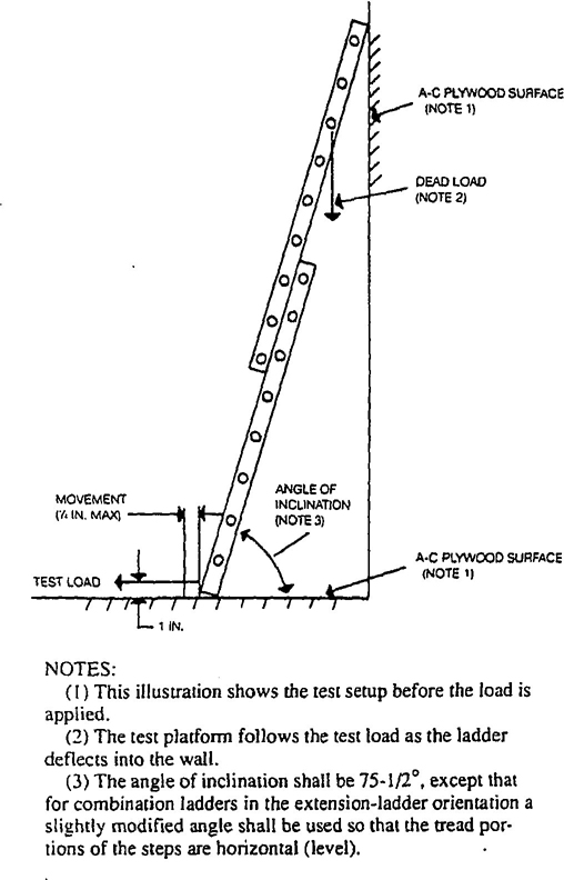
(1) This illustration shows the test setup before the load is applied
(2) The test platform follows the test load as the ladder deflects into the wall
(3) The angle of inclination shall be 75-1/2°, except that for combination ladders in the extension-ladder orientation a slightly modified angle shall be used so that the tread portions of the steps are horizontal (level).
Fig. 1
Inclined Load Test
Fig. 1
Inclined Load Test
| Duty Rating and Type | Working Load (pounds) |
Test Load (pounds) |
|---|---|---|
| Extra heavy duty - Type IA | 300 | 1000 |
| Heavy duty - Type I | 250 | 1000 |
| Medium duty - Type II | 225 | 900 |
| Light duty - Type III | 200 | 800 |
are destructive in nature, ladders subjected to quality control tests may be subsequently placed in field service.
7.1.7 In-service tests may be conducted in the field by the manufacturer, the acual owner, the user, or their agents to evaluate the condition of the product following actual field service. Ladders that conform to the in-service use tests shall continue to be employed.
7.1.8 The development and on-going implementation of overall quality control shall be the responsibility of each individual manufacturer.
7.1.9 Conformance to the design verification test requirements, where applicable, shall be determined five minutes after load removable.
7.1.10 The test load shall be applied slowly, using care to avoid impact loading during the test.
7.2 Tests For Single and Extension Ladders
7.2.1 Simulated In-Use Inclined Load Test.
Note: This is a design verification test. The ladder shall be fully extended and supported as shown in Fig. 1. The load shall be applied equally to both side rails on the lowest fly rung above the overlap using two 3-½ inch straps, each located next to a rail and centrally loaded through an equalizer bar over the climbing side of the ladders. All supporting and loading apparatus shall conform to that shown in Fig. 1 or shall be such as to produce equivalent results.
The ladder shall be loaded in accordance with Table 15. The full load shall be applied for a period of 1 minute before release. The ladder shall sustain this load without ultimate failure. Permanent deformation (set) shall be allowed. This test shall be used only for design verification. It shall not be employed for quality control or field inspection purposes.
7.2.2 Hardware Test Requirements For Extension Ladders
7.2.2.1 Single Lock Load Test. Note: This is a design verification test. The test unit shall either be the shortest full-size ladder manufactured or a unit only of sufficient length for test purposes. If a full-size ladders is used, the fly section shall be extended one rung beyond the minimum working length of the ladder. Short test units shall consist of portions of the base and fly sections of the extension ladder, with all the hardware or fittings attached.
The test unit shall be set, as shown in Fig. 4, at a 75-½° working angle, with one lock removed. For combination ladders in the extension-ladder orientation, a slightly modified angle shall be used so that the tread portions of the steps are horizontal (level). A downward distributed load, in accordance with Table 16, shall be applied to both siderails on the lowest fly rung above the overlap using two 3-½ inch
30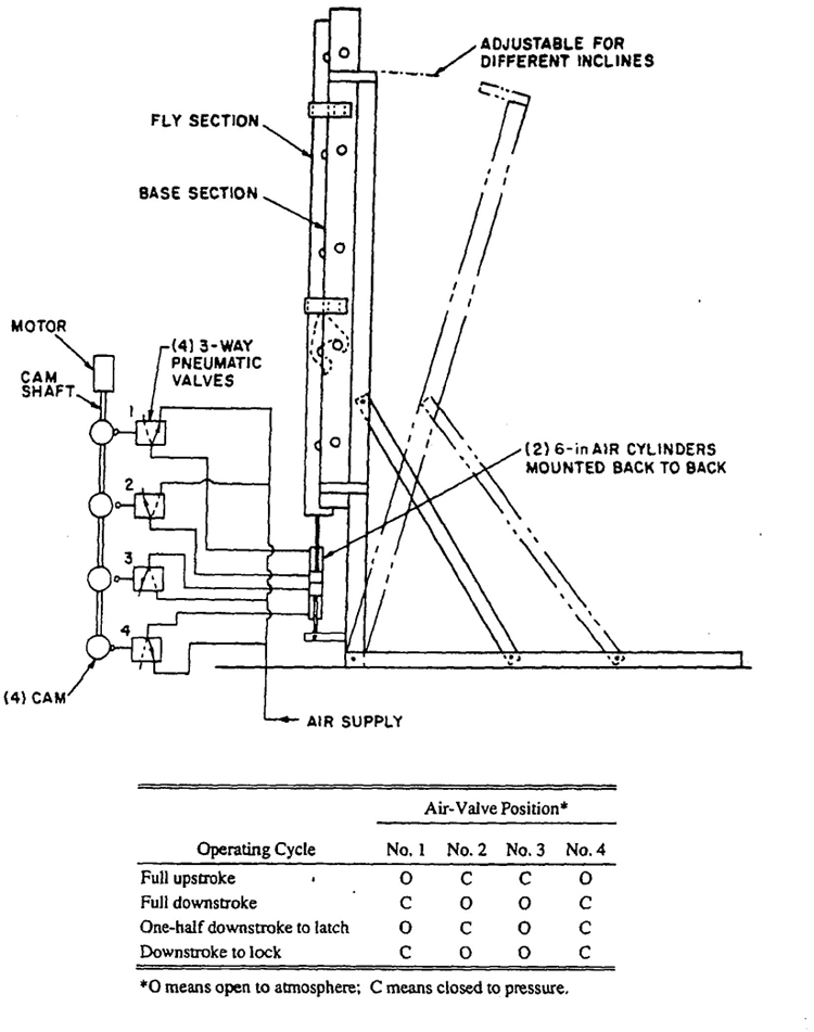
Fig. 2
Cyclic Rung Lock Test Arrangement
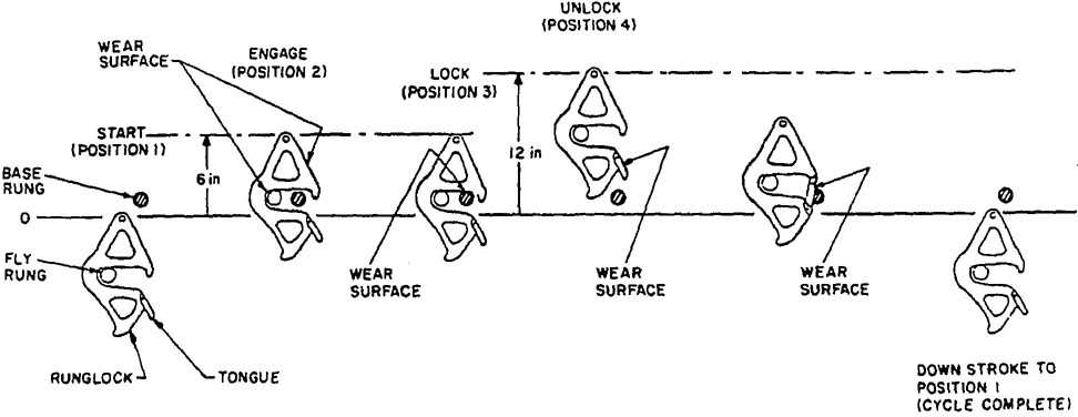
Fig. 3
Rung Lock Testing Cycle
| Duty Rating and Type | Compression Test Load (pounds) |
Single Lock Test Load (pounds) |
|---|---|---|
| Extra heavy duty – Type IA | 1200 | 1000 |
| Heavy duty – Type I | 1000 | 1000 |
| Medium duty – Type II | 900 | 900 |
| Light duty – Type III | 800 | 800 |
straps, each located next to a rail and centrally loaded through an equalizer bar over the climbing side of the ladder.
The locks shall withstand this test with no permanent deformation (set) or other visible weakening of the locks. Permanent deformation in other parts of the ladder structure including racking of the ladder structure due to the test is not a test failure. However, the ladder shall still support the test load after the application of the load, even if the rung assumes permanent deformation (set).
7.2.2.2 Lock Tip Load Test. Note: This is a design verification test. The test unit shall be either the shortest full-size ladder manufactured or a unit only of sufficient length for test purposes. If a full-sized ladder is used, the fly section shall be extended a minimum of one rung beyond the minimum working length of the ladder. Short test units shall consist of portions of the base and fly sections of the extension ladder, with the locks attached.
The test unit shall be set at a 75-½° working angle, as shown in Fig. 6a and b, with both locks partially engaged. For combination ladders in the extension-ladder orientation, a slightly modified angle shall be used so that the tread portions of the steps are horizontal (level). The bottom end of the ladder shall be prevented from slipping by a block or equivalent means. The top of each lock shall bear on the center of a steel test fixture placed over the top of a rung, as shown in Fig. 6a and b. During the test, each lock shall be prevented from pivoting by means located adjacent to its pivot point, but which shall not affect that portion of the lock under test in any way.
A downward distributed load, in accordance with Table 16, shall be applied for a period of one minute equally to both side rails on the lowest fly rung above the overlap, using two 3-½-inch straps, each located next to a rail and centrally loaded through an equalizer bar over the climbing side of the ladder. Permanent deformation in other parts of the ladder structure due to the test is not a test failure. However, the ladder shall still support the test load after the application of the load, even if the rung assumes permanent deformation (set).
32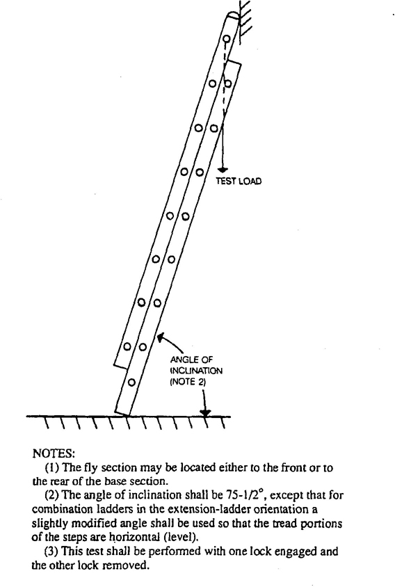
NOTES
(1) The fly section may be located either to the front or to the rear of the base section.
(2) The angle of inclination shall be 75-1/2°, except that for combination ladders in the extension-ladder orientation a slightly modified angle shall be used so that the tread portions of the steps are horizontal (level).
(3) This test shall be performed with one lock engaged and the other lock removed.
Fig. 4
Single Lock Load Test
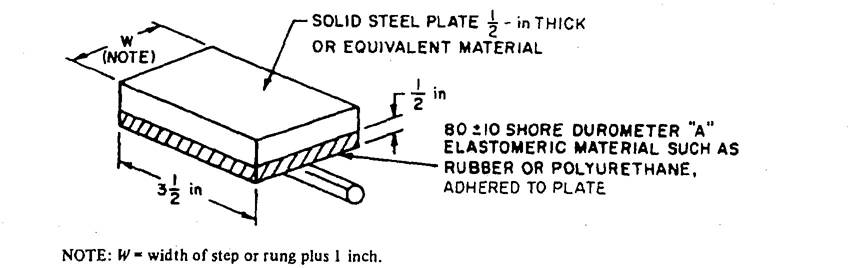
Fig. 5
Standard Loading Block
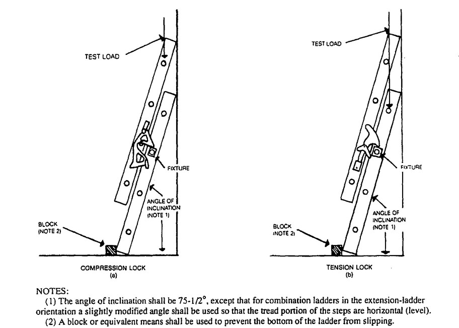
NOTES
(1) The angle of inclination shall be 75-1/2°, except that for combination ladders in the extension-ladder orientation a slightly modified angle shall be used so that the tread portion of the steps are horizontal (level).
(2) A block or equivalent means shall be used to prevent the bottom of the ladder from slipping.
Fig. 6
Lock Tip Load Test
7.2.2.3 Cyclic Rung Lock Test. Note: This is a design verification test. A machine equivalent to that pictured in Fig. 2 shall be used to operate the rung lock through the following cycle, as shown in Fig. 3.
(1) One 6-inch upstroke to allow rung lock to engage rung
(2) Full 6-inch downstroke to lock run lock on rung
(3) Full 12-inch upstroke to disengage rung lock
(4) Full 12-inch downstroke to return rung lock to starting position
Locks shall be tested with the ladder at a 75-½° angle. For combination ladders in the extension-ladder orientation a slightly modified angle shall be used so that the tread portions of the steps are horizontal (level). Spring locks shall be tested with the ladder in the vertical position.
The rung lock may be manually lubricated prior to or during the test. The stroke speed shall be 6 to 12 inches per second. A minimum of 6000 cycles shall be imposed. Any malfunction of the rung lock or fracture of its components, including springs, shall be considered as a failure to meet this requirements. The presence of wear that does not effect the proper functioning of the lock shall not constitute failure.
This test is not intended to apply to fixed-type locks used on extension ladders or combination ladders.
7.2.3 Side-Rail Cantilever Dynamic Drop Test for Single and Extension Ladders. Note: This is a design verification test. The test unit shall be the longest extension ladder for each base section and the longest single ladder for each rail size. An extension ladder shall be opened 1 foot for the drop test.
The test ladder shall be placed in a horizontal position, with the rungs vertical. The top section shall be supported 6 inches from the very top of the top section so that the lower rail of the bottom section is 36 inches from a concrete floor. (See Fig. 7)
To perform the drop test, both rails of the base section shall be guided in a vertical plane during a free-fall drop. A ladder shall be considered to have passed the test if there is no visual damage to the rail.
7.2.4 Ladder Section Twist Test for Single and Extension Ladders. Note: This is a design verification test. The test unit shall consist of any length ladder base section supported over a 7-foot test span. The ladder shall be placed in a flat horizontal position and supported at each end as depicted in Fig. 8. The horizontal support for the ladder on one end shall be
34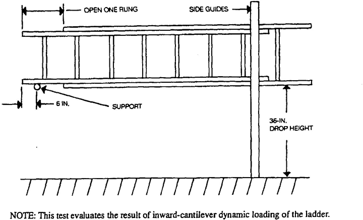
Fig. 7
Side-Rail Cantilever Dynamic Drop Test
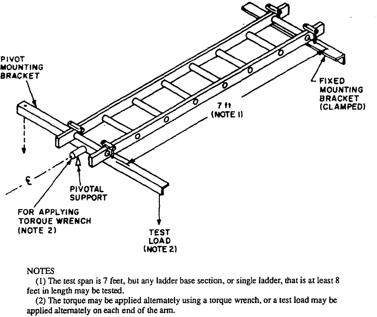
NOTES
(1) The test span is 7 feet, but any ladder base section, or single ladder, that is at least 8 feet in length may be tested.
(2) The torque may be applied alternately using a torque wrench, or a test load may be applied alternately on each end of the arm.
Fig. 8
Single or Extension-Ladder Twist Test
| Duty Rating and Type | Test Load (pounds) |
Maximum Allowable Angle of Twist Ø* (degrees) |
|---|---|---|
| Extra heavy duty – Type IA | 300 | 14 |
| Heavy duty – Type I | 250 | 18 |
| Medium duty – Type II | 225 | 20 |
| Light duty – Type III | 200 | 22 |
| *Ø= 38 − 0.08X, where Ø = maximum allowable angle of twist (degrees) and X = working load (pounds). | ||
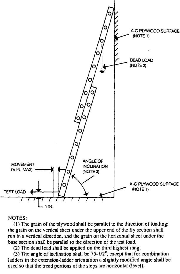
NOTES:
(1) The grain of the plywood shall be parallel to the direction of loading: the grain on the vertical sheet under the upper end of the fly section shall run in a vertical direction, and the grain on the horizontal sheet under the base section shall be parallel to the direction of the test load.
(2) The dead load shall be applied on the third highest rung.
(3) The angle of inclination shall be 75-1/2°, except that for combination ladders in the extension-ladder orientation a slightly modified angle shall be used so that the tread portions of the steps are horizontal (level).
Fig. 9
Bottom Slip Test
| Duty Rating and Type | Test Weight on 3rd Highest Fly Rung (pounds) |
Horizontal Pulling Force (pounds) |
|---|---|---|
| Extra heavy duty - Type IA | 300 | 50 |
| Heavy duty - Type I | 250 | 50 |
| Medium duty - Type II | 225 | 50 |
| Light duty - Type III | 200 | 50 |
fixed. An initial preload of 600 inch-pounds, applied in a clockwise direction, shall be used to establish a reference for angular deflection, after which the ladder shall be unloaded. A torque of 1200 inch-pounds shall than be applied in accordance with one of the two methods shown in Fig. 8. The torque shall be applied first in a clockwise and then in a counterclockwise direction. The angle of twist measured from the horizontal position shall not be greater than the values in Table 17. Attention shall be given to ensure that the ladder is tightly clamped onto the test fixtures during this test.
7.2.5 Bottom Slip Test. Note: This is a design verification test. Single and extension ladders shall be tested for skid resistance as shown in Fig. 9. The test unit shall be a 16-foot extension ladder in the fully extended position. The test surface shall be A-C plywood, which shall be presanded using 320 fine wet/dry sandpaper. The “A” side of the plywood shall be placed in contact with the bottom of the ladder. The surface that the top of the fly section rests against shall also be A-C plywood, similarly treated.
A weight, in accordance with Table 18, shall be attached to the third highest fly rung. A horizontal pulling force, in accordance with Table 18, statically applied to the bottom of the ladder at 1 inch above the test surface, shall not cause any noticeable movement across the test surface.
7.2.6 Multisection Extending Force Test for Extension Ladders. Note: This is a design verification test. The test unit shall be set in a vertical position, at the minimum working length of the ladder. The base section may be braced or otherwise held to maintain vertical alignment. A measured downward force shall be applied to the rope if the ladder has a rope and pulley system installed. The force shall be smoothly applied to cause vertical extension of the fly section of 2 feet or more, at a rate of ½ to 1 foot per second.
For those ladders not equipped with rope and pulley, the measured force shall be applied vertically to the bottom rung of the top section. The maximum measured force that occurs during each pull shall be recorded. Three test pulls shall be done for each ladder, and the maximum forces shall be averaged for the three pulls. This average maximum force shall not exceed two times the weight of the ladder top section.
7.3 Tests for Stepladders, Platform Ladders, Trestle Ladders, Extension Trestle Ladders, and Stepstools.
7.3.1 Compression Test. Note: This is a design verification test. A load test of the entire ladder or stepstool shall be made with the ladder in an open position, as shown in Fig. 10. A uniformly distrubuted load, in accordance with Table 16, shall be applied for a minimum period of 1 minute to the ladder top cap or platform. Trestle ladders and the base section of extension trestle ladders shall be subjected to twice the test loads in Table 16 by simultaneously applying the test load to both sections of the ladder at the top cap or via a loading block or plate across the top of the rails when no top cap is used. For the extension trestle, the load shall be applied via a loading block or plate across the top of the rails of the extended section when that section is extended a minimum of 1 foot above the minimum working height. This test will also serve as a design verification test of the locking mechanism. The unit shall withstand the load without test failure.
7.3.2 Bucket Shelf Test for Stepladders. Note: This is a design verification test. The bucket shelf shall be constructed so as to support a distributed load of 100 pounds, applied to the shelf for a minimum of 1 minute while the ladder is in an open position with the spreaders locked. The bucket shelf shall withstand the load without ultimate failure.
7.3.3 Front Stability Test for Stepladders, Platform Ladders, Trestle Ladders, Extension Trestle Ladders, and Step Stools. Note: This is a design verification test. The ladder shall be set in the open position on a level floor. A uniformly distributed load, in accordance with Table 19. comprising lead
37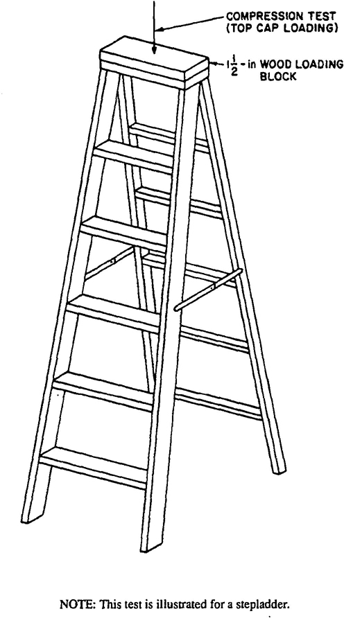
NOTE: This test is illustrated for a stepladder.
Fig. 10
Compression Test
| Duty Rating and Type | Distributed Load† | Front Pulling Force | Side Pulling Force | Rear Pulling Force | Torsional Stability Pulling Force | |
|---|---|---|---|---|---|---|
| Platform Ladders | Step Ladders | |||||
| Extra heavy duty - Type IA | 200 | 25 | 20 | 35 | 45 | 30 |
| Heavy duty - Type I | 200 | 25 | 20 | 35 | 45 | 30 |
| Medium duty - Type II | 200 | 25 | 20 | 35 | 45 | 25 |
| Light duty - Type III | 200 | 25 | 20 | 35 | 45 | 20 |
| * All quantities are in pounds. | ||||||
| †This load is applied at the second highest step or platform. | ||||||
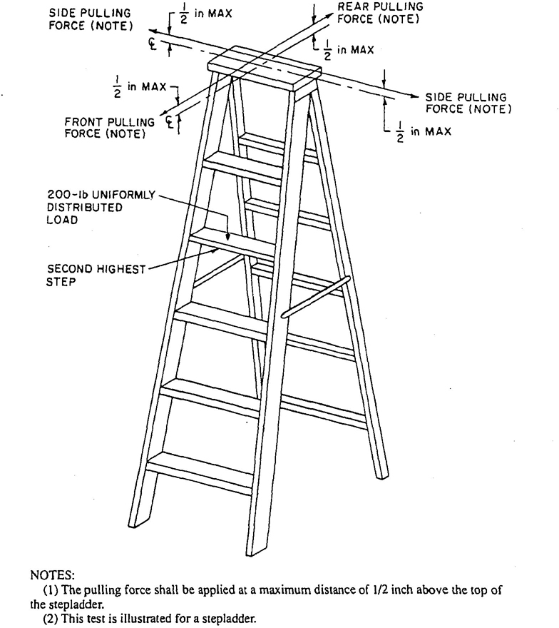
NOTES:
The pulling force shall be applied at a maximum distance of 1/2 inch above the top of the stepladder.
(2) This test is illustrated for a stepladder.
Fig. 11
Front, Side, and Rear Stability Tests
weights or the equivalent to maximize the density of the loading medium, shall be applied to the second highest step, rung, or the platform (the highest proper standing level), as shown in Fig. 11. (For an extension trestle ladder, the load shall be applied to the second highest extension-section rung.)
The ladder shall then be subjected to a horizontal pulling force, in accordance with Table 19, applied at the geometric center of the stepladder top cap, at a distance of not more than ½ inch above its top surface, towards the front of the ladder, as shown in Fig. 11. The pulling force shall be applied to the top horizontal guard rail member of platform ladders, and to the apex of the base section of trestle and extension trestle ladders. Step stools shall be loaded with the distributed load on the top cap, and the pulling force shall be applied to the top cap also. The test surface shall be such as to ensure that the ladder does not slip or slide during the test.
During this test, the minimum load that causes the ladder to tip over shall not be less that the value shown in Table 19. Ladders equipped with a bucket shelf shall be tested with the bucket shelf in the in-use position.
7.3.4 Side Stability Test for Stepladders, Platform Ladders, Trestle Ladders, Extension Trestle Ladders, and Step Stools. Note: This is a design verification test. The side stability of a ladder shall be measured with the ladder set in an open position on a level floor. A uniformly distributed load, in accordance with Table 19, comprising lead weights or the equivalent to maximize the density of the loading medium, shall be applied to the second highest step, rung, or the platform, as shown in Fig. 11. (For an extension trestle ladder the load shall be applied to the second highest extension-section rung.)
The ladder shall then be subjected to a horizontal pulling force, in accordance with Table 19, applied to the side of the front rail, at the geometric center of the stepladder top cap, at a distance of not more than ½ inch above its top surface, as shown in Fig. 11. The pulling force shall be applied to the top horizontal guard rail member of platform ladders and to the apex of the base section of trestle and extension trestle ladders. Step stools shall be loaded with the distributed load on the top cap, and the pulling force shall be applied to the top cap also. The test surface shall be such as to ensure that the ladder does not slip or slide during the test.
During this test, the minimum load that causes the ladder to tip over shall not be less than the value shown in Table 19. The test shall be run with the force applied to both sides and the values shall be averaged to obtain the minimum load. Ladders equipped with a bucket shelf shall be tested with the bucket shelf in the in-use position.
7.3.5 Rear Stability Test for Stepladders, Platform Ladders, Trestle Ladders, Extension Trestle Ladders, and Step Stools. Note: This is a design verification test. The rear stability of a ladder shall be measured by placing the ladder in an open position on a level floor. A uniformly distributed load, in accordance with Table 19, comprising lead weights or the equivalent to maximize the density of the loading medium, shall be placed on the second highest step, rung, or the platform (the highest proper standing level), as shown in Fig. 11. (For an extension trestle ladder the load shall be applied to the second highest extension-section rung.)
The ladder shall then be subjected to a horizontal pulling force, in accordance with Table 19, applied to the geometric center of the stepladder top cap, at a distance of not more than ½ inch above its top surface, in a rearward direction, as shown in Fig. 11. The pulling force shall be applied to the top horizontal guard rail member of platform ladders and to the apex of the base section of trestle and extension trestle ladders and to the top cap or combination ladders on the top step when no cap is used. Step stools shall be loaded with the distributed load on the top cap, and the pulling force shall be applied to the top cap also. The test surface shall be such as to ensure that the ladder does not slip or slide during the test.
During this test, the minimum load the causes the ladder to tip over shall not be less that the value shown on Table 19. Ladders equipped with a bucket shelf shall be tested with the bucket shelf in the in-use position.
7.3.6 Torsional Stability Test for Stepladders, Platform Ladders, Trestle Ladders, and Extension Trestle Ladders. Note: This is a design verification test. The test unit shall be placed on a level floor, in the fully opened position, with the spreaders properly set. A 200-pound distributed dead load, comprising lead weights or the equivalent to maximize the density of the loading medium, shall be applied to the ladder top cap, platform, or top step when no top cap is used, as shown in Fig. 12. A horizontal force, in accordance with Table 19, directed to the rear of the ladder, shall be applied to the ladder top cap at a distance of 18 inches from the vertical centerline of the ladder, as shown in Fig. 20. The force shall be maintained perpedicular to the moment arm, with a tolerance of ±10°, during the test. The test shall be conducted on a dry, unwaxed vinyl tile floor.
Relative movement in excess of 1 inch of the ladder with respect to the floor, any damage or visible
40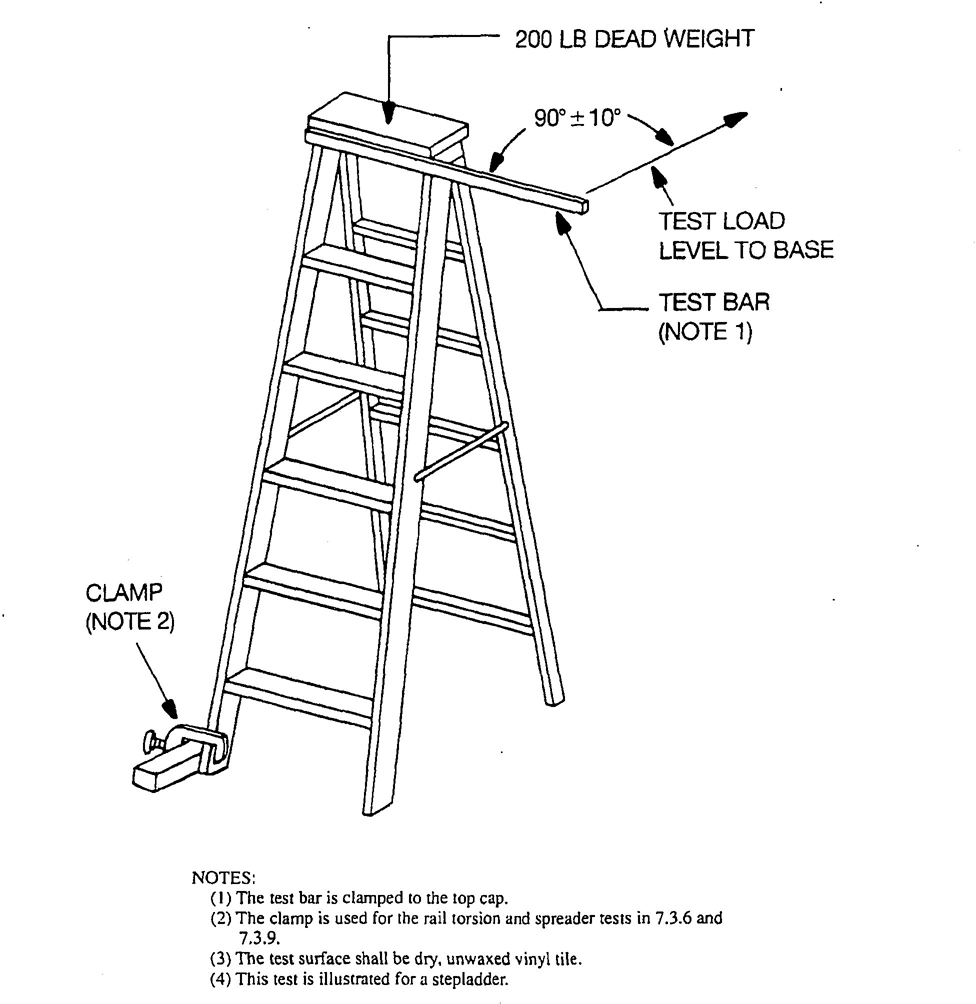
NOTES:
The test bar is clamped to the top cap.
The clamp is used for the rail torsion and spreader tests in 7.3.6 and 7.3.9.
The test surface shall be dry, unwaxed vinyl tile.
This test is illustrated for a stepladder.
Fig. 12
Torsional Stability and Rail Torsion and Spreader Tests
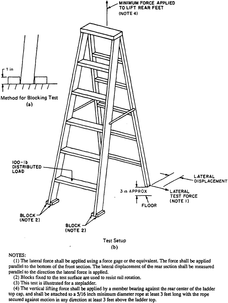
NOTES:
(1) The lateral force shall be applied using a force gage or the equivalent. The force shall be applied parallel to the bottom of the front section. The lateral displacement of the rear section shall be measured parallel to the direction the lateral force is applied.
(2) Blocks fixed to the test surface are used to resist rail rotation.
(3) This test is illustrated for a stepladder.
(4) The vertical lifting force shall be applied by a member bearing against the rear center of the ladder top cap, and shall be attached to a 5/16 inch minimum diameter rope at least 3 feet long with the rope secured against motion in any direction at least 3 feet above the ladder top.
Fig. 13
Racking Test
| Deflection | |||
|---|---|---|---|
| Ladder Size (feet) | Type-I and -IA Ladders Y = 1.35 X + 3.9 |
Type-II Ladders Y = 1.35 X + 7.9 |
Type-III Ladders Y = 1.35 X + 7.9 |
| 3 | 7.95 | 11.95 | 11.95 |
| 4 | 9.30 | 13.30 | 13.30 |
| 5 | 10.65 | 14.65 | 14.65 |
| 6 | 12.00 | 16.00 | 16.00 |
| 7 | 13.35 | 17.35 | |
| 8 | 14.70 | 18.70 | |
| 10 | 17.40 | 21.40 | |
| 12 | 20.10 | 24.10 | |
| 14 | 22.80 | ||
| 16 | 25.50 | ||
| 18 | 28.20 | ||
| 20 | 30.90 | ||
| * All deflections are measured in inches. †Y = lateral racking deflection (inches) during a 6-pound pull; X = ladder size (feet). |
|||
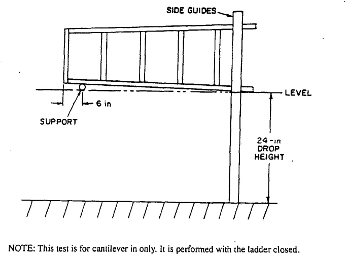
NOTE: This test is for cantilever in only. It is performed with the ladder closed.
Fig. 14
Dynamic Drop Test
weakening of the ladder structure or component, or any significant visible major damage from permanent deformation (set) of the test unit upon release of the test force, shall constitute failure to meet this requirement. Minor permanent deformation (set) of individual ladder components, such as diagonal braces or rear horizontal braces, of less than ⅛ inch shall not constitute test failure.
Ladders equipped with a bucket shelf shall be tested with the bucket shelf in the in-use position. This test is not applicable to step stools, platform ladders less than 3 feet in size, and other step-type ladders less that 5 feet in size.
7.3.7 Racking Test for Stepladders, Platform Ladders, Trestle Ladders, and Extension Trestle Ladders. Note: This is a design verification test. The test unit shall be placed on a level floor, in the fully opened position, with the spreaders properly set. Both front feet shall be individually blocked to prevent movement relative to the floor, as shown in Fig. 13a. A 100-pound distributed dead load shall be applied to the bottom step; no part of the load shall contact either of the two front rails during the test.
A vertical pulling force shall be applied to the rear of the ladder top cap, top guard rail, or top step when no top cap is used, so as to lift both rear feet and provide a 3-inch clearance between the rear feet and the floor. A 4-pound preload, prior to the 6-pound lateral pulling force shall be applied at the bottom of one rear rail, using a force gage or the equivalent, as shown in Fig. 13b, and the lateral displacement of that rear rail shall be measured relative to its no-load position. The maximum lateral displacement shall not exceed the value given in Table 20.
Ladders equipped with a bucket shelf shall be tested with the bucket shelf in the in-use position. This test is not applicable to step stools.
7.3.8 Front Rail and Back Leg Dynamic Drop Test for Stepladders, Platform Ladders, Trestle Ladders, Extension Trestle Ladders, and Step Stools. Note: This is a design verification test. The test unit shall be the tallest ladder for each rail size, with the same bottom bracing for each unit tested. Stepladders shall be tested in a closed position, with the ladder horizontal so that the steps are vertical. The top of the ladder shall be supported 6 inches from its top so that the bottom of the lower rail is 24 inches from a concrete floor, as shown in Fig. 14.
To perform the drop test, the front rail and back legs shall be guided in a vertical plane during a freefall drop. The allowable permanent deformation (set) of the lower front rail or lower back leg shall not exceed ¼ inch.
7.3.9 Rail Torsion and Spreader Test for Stepladders, Platform Ladders, Trestle Ladders, and Extension Ladders. Note: This is a design verification test. The test unit shall be placed on a level floor, in the fully opened position, with the spreaders properly set. A 200-pound distributed dead load, comprising lead weights or the equivalent to maximize the density of the loading medium, shall be applied to the ladder top cap, platform or top step when no top cap is used. A horizontal force, directed to the rear of the ladder, shall be applied to the ladder top cap at a distance of 18 inches from the vertical centerline of the ladder, as shown in Fig. 12. The force shall be perpendicular to the moment arm, with a tolerance of ± 10°, when the test load is reached. The front side rail, opposite from the side where the horizontal force is applied, shall be blocked from movement. The test shall be conducted on a dry, unwaxed vinyl tile floor.
The test unit shall withstand a horizontal force of not less that the value in Table 21, without the spreaders locking, any damage or visible weakening of the ladder or components, or any significant visible major permanent deformation (set) of the test unit upon release of the test force. Minor permanent deformation (set) of individual ladder components, such as diagonal braces or rear horizontal braces, of less that ⅛ inch, shall not constitute test failure.
Ladders equipped with a bucket shelf shall be tested with the bucket shelf in the in-use position. This test is not applicable to step stools.
7.3.10 Stepladder Slip Test. Note: This is a design verification test. Stepladders shall be tested for skid resistance as shown in Fig. 15. The test unit shall be a 6-foot stepladder, fully opened. A uniformly distributed load of 200 pounds shall be placed on the second highest step. A horizontal pulling force of 35 pounds, statically applied to the bottom of the ladder at 1 inch above the test surface, shall not cause any movement in excess of ¼ inch across the test surface. The test surface shall be a dry, unwaxed vinyl tile floor.
| Duty Rating and Type | Working Load (pounds) |
Rail Torsion Test Force (pounds) |
|---|---|---|
| Extra heavy duty - Type IA | 300 | 125 |
| Heavy duty - Type I | 250 | 100 |
| Medium duty - Type II | 225 | 75 |
| Light duty - Type III | 200 | 50 |
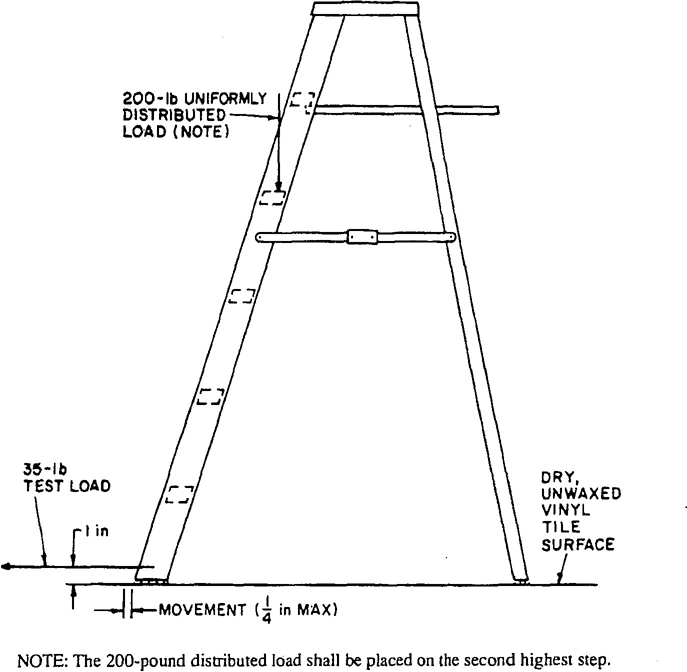
NOTE: The 200-pound distributed load shall be placed on the second highest step.
Fig. 15
Stepladder Slip Test
7.4 Labeling Tests
7.4.1 General. The following procedures are designed to evaluate the suitability of primary hazard (danger and caution), safety use instruction (safety first), and product data information (notice) labels for application to ladders, and the performance of printed labels applied to surfaces representative of those employed in the intended application.
NOTE: See Section 9, Labeling/Marking Requirements, for layout detail, color, and format of labels.
Unless otherwise specified, the labels are applied to the appropriate surfaces and conditioned for 24 hours at 73° F (±° F) and 50% ±5% humidity (±5%). Satisfactory results are needed on three samples for each test to fulfill the requirements.
It is not intended that the tests shall be conducted on a progressive basis on one set of test samples. After each environment test, the samples should be conditioned at 73° F (±5° F and 50% relative humidity ±5% for 24 hours before subsequent test are conducted.
7.4.2 Tests
NOTE: These tests are all design verification tests and should be performed on a standard substrates rather than on actual ladders. The substrates shall be southern yellow pine or the manufacturer's standard rail material with nominal thickness of ¾ inch.
Labels shall be mounted using a 4-½-pound weighted roller and then cured for 24 hours before being subjected to test.
7.4.2.1 Adhesion Test. The test shall be conducted on a new label that has not been subject to other tests in 7.4.2, according to ASTM D903-49 (1988), Test for Peel or Stripping Strength of Adhesive Bonds.3 A minimum force of 30 ounces shall be required to remove the label.
7.4.2.2 Scratch Resistance Test. The label shall resist defacement or removal when a flat metal blade 1/32-inch thick, held at a right angle to the test
3 Available from the American Society for Testing and Materials. 1916 Race Street. Philadelphia, Pa. 19103.
45panel, is scraped across it. This test shall be run on labels before and immediately after the water immersion test.
7.4.2.3 Water Immersion Test. Applied labels shall be immersed in water, label side down, with the water level a minimum of 1/8 inch above the label, for 48 hours at 75°F. No significant change shall occur in the legibility of the labels or in their adhesion to the ladder surface (as evidence by delamination or curling) following the test.
7.4.2.4 Oven Aging Test. Applied labels shall be placed in an oven maintained at a temperature of be placed in an oven maintained at a temperature of 158°F (70°C) for 240 hours. No significant change shall occur in the legibility of the labels or in their adhesion to the ladder surface (as evidence by delamination or curling) following the test.
8.1 General
8.1.1 For maximum serviceability and safety and to eliminate unnecessary damage to equipment, good safe practices in the use and care of ladder equipment shall be employed by the users. The guidelines discussed in this section constitute the most appropriate and proper procedures for the car and use of ladders.
8.1.2 A comparison of studies within A 14 jurisdiction, by government bodies, by other researcher, and in the ILO4 Publication CIS-12, Ladders, indicates a close correlation between major accident causes and the failure to follow guidelines like those provided in this section.
8.1.3 The major causes of falls from self-supported portable ladders are lack of stability and sliding. Major causes of falls from non-self-supporting portable ladders are lateral sliding at the top support, and human slip. Table 22 provides a summary of significant accident causes.
8.1.4 Proper selection of a ladder is essential for ensuring safety and reducting the potential for accidents.
8.1.5 Proper use of a ladder will contribute significantly to safety. Factors contributing to falls include haste, sudden movement, lack of attention during use, ladder condition (worn or damaged), user's age or physical condition, or both, and the user′s foot-wear. The likelihood of falls is not increased by the user′s excessive weight or size. However, improper climbing posture creating user clumsiness on the ladder may cause falls.
8.1.6 The safe useful life of the ladder is dependent upon its proper in-service care. While ladders are designed for extended service, it is necessary to provide periodic in-service care and maintenance to ensure their continued safe use. Ladders are not designed or intended to possess an infinite safe useful life.
8.1.7 The information provided in the balance of this section principally addresses stepladders and extension ladders. The principles, however, are applicable to all self-supporting and non-self-supporting portable ladders.
8.2 Selection
8.2.1 Ladder Selection. Portable ladders are designed for one-man use to meet the requirements of the man, the task, and the environment. This section covers the factors involved in making the proper ladder selection. Product information data necessary for proper ladder selection are found on the ladder rail.
8.2.1.1 Duty Rating. Ladders have been designed in four duty classifications:
| Duty Rating | Ladder Type | Working Load (pounds) |
|---|---|---|
| Extra heavy duty | IA | 300 |
| Heavy duty | I | 250 |
| Medium duty | II | 225 |
| Light duty | III | 200 |
8.2.1.2 Loading and Service. Users shall give consideration to the length required, the working load, the duty rating, and frequency of use to which the ladder will be subjected. Users shall not overload a ladder.
The following criteria shall be used when purchasing or using a ladder:
(1) Extra Heavy Duty. For users requiring a 300-pound working load or duty rating, such as industry, utilities, contractors, and the like.
(2) Heavy Duty. For users requiring a 250-pound working load or duty rating, such as industry, utilities, contractors, and the like.
(3) Medium Duty. For users requiring a 225-pound working load or duty rating, such a painters, offices, light maintenance, and the like.
(4) Light Duty. For users requiring no more than a 200-pound working load or duty rating, such as general household use. Light-duty ladders shall not be used with ladder jacks or scaffolds planks, or both.
4 Available from the Internation Occupational Safety and Health Information Centre. International Labour Office, CH1211. Geneva 22. Switzerland.
46| Possible Factors Involved in Accident | ||||||
|---|---|---|---|---|---|---|
| Ladder Design | Cause of Accident | Base Support or Surface | Top Support | Set-Up | User Location | Ladder Selection and Condition |
| Self-supporting (stepladder) | Stability | Soft Uneven Unstable surface Slipper surface Differences in firmness of surface Slope of surface |
Not applicable | Unlocked spreaders One or more feet unsupported Used unstable or insufficient supports Ladder not close enough to work location User's physical condition |
Above “highest standing level” label Reaching out too far particularly laterally Climbing onto ladder from above Handling heavy loads or unstable objects Applying side load |
Too short (size) Incorrect ladder type (IA. I. II. or III) Incorrect style ladder (for example, platform or single versus stepladder) Use of improper equipment (for example, ladder versus scaffold) |
| Sliding | Uneven surface Low friction Unstable surface Ice snow or wet surface Slippery surface |
Not applicable | Used as a non-self-supporting ladder Ladder not close enough to work location Wom, missing or contaminated feet |
Reaching out too far Stepping off ladder Applying side load | Use of improper equipment (for example, ladder versus scaffold) Removal or deterioration of slip-resistant ladder feet |
|
| Non-self-supporting (extension and single) | Human slip | Not applicable | Not applicable | Pitch (angle) too steep (especially with flat rungs) User's physical condition or shoes |
Descending | Dirty, oily, or icy step surfaces Use of improper equipment (for example, ladder versus scaffold) |
| Lateral sliding (left or right) at top support | Uneven surface Differences in firmness of surface Unstable surface |
Uneven surface Slippery surface Unstable surface (pole, tree, corner of building, and the like) Ice, snow, or wet surface Insufficient top support |
Not tied off Not held at base Inadequate or excessive extension above top support Ladder not close enough to work location Pitch (angle) too steep Feet unsupported or unstable Extension locks not engaged |
Getting on or off ladder to roof Reaching out too far laterally Applying side load |
Too short or too long (size) Not extended far enough (too sleep) Use of improper equipment (for example, ladder versus scaffold) |
|
| Outward sliding at lower base support | Unstable surface Low friction Loose surface Ice, snow, or wet surface Slippery surface |
Overextension above top support | Used unstable or insufficient supports Pitch (angle) too flat Ladder not footed Ladder not tied off or blocked Wom, missing or slippery feet Improper selection of feet or skid-resistant bearing surfaces Extension locks engaged |
Above “highest standing level” label Sliding tendency increases above midpoint of ladder working length Careless climbing onto or off of ladder (from or to roof, and the like Applying side load |
Wrong foot or skid-resistant bearing surface Too long (size) or extended too far Use of improper equipment (for example. ladder versus scaffold) |
|
| Extension Ladder Size | Maximum Working Length | Height to Top Support on Wall | Height to Roof Eave with 1-to 3-Foot Extension |
|---|---|---|---|
| 16 | 13 | To 12-1/2 | 9-1/2-11-1/2 |
| 20 | 17 | 12-1/2-16-1/2 | 13-1/2-15-1/2 |
| 24 | 21 | 16-1/2-20 | 17-19 |
| 28 | 25 | 20-24 | 21-23 |
| 32 | 29 | 24-28 | 25-27 |
| 36 | 33 | 28-32 | 29-31 |
| 40 | 36 | 32-35 | 32-34 |
| *All quantities are in feet. | |||
8.2.1.3 Proper Size
8.2.1.3.1 Extension Ladders. Selection of proper extension-ladder size requires knowledge of the vertical height or elevation to the top support point. Where the top support is a roof eave, additional working length is needed to permit the required 1- to 3-foot extension beyond this point. The highest standing level shall also be considered, although the actual dimension will change as the ladder is extended. The nominal relationships among size, working length, and height to the top support point are given in Table 23.
8.2.1.3.2 Stepladders. The highest standing level is constant for a specific stepladder. Typical relationships are as follows:
| Stepladder Size (feet) | Recommended Highest Standing Level |
|---|---|
| 4 | 1 foot, 11 inches |
| 5 | 2 feet, 10 inches- 2 feet, 11 inches |
| 6 | 3 feet, 10 inches |
| 7 | 4 feet, 9 inches- 4 feet, 10 inches |
| 8 | 5 feet, 9 inches- 5 feet 10 inches |
| 10 | 7 feet, 8 inches- 7 feet, 9 inches |
The maximum work height is then established by adding the user's height and safe reach to the highest standing level dimension.
8.2.1.3.3 User On-Ladder Location. There are situations in which the use of a particular size ladder creates a gap in the height that can be reached by the user. For example, extension ladders of 28-foot size and longer cannot be used to work on a wall below a certain height because the user would be too far out from the wall. Usually the lower portion of the wall can be reached from the ground, which means up to a height of about 7 feet. When this 28-foot extension ladder is closed to 14 feet, working on a wall below 10 feet becomes a problem
These conditions create a gap between 7 and 10 feet in height where another ladder selection is recommended. To work in this zone, a shorter non-self-supporting ladder or a self-supporting ladder such as a stepladder should be considered.
8.2.1.3.4 Work Site Restrictions on.
Working Length. In cases where the work site imposes a height restriction on the non-self-supporting ladder's working length, the user may find that longer ladders are not capable of erection at the proper bottom of inclination of 75-1/2° To safeguard against bottom sliding, select a shorter extension ladder or a single ladder.
8.2.2 In choosing between a self-supporting and a non-self-supporting ladder, an important factor to consider is the bottom and top support conditions. A stepladder requires level support for four rails. If such support is lacking or is not convenient, and if a top support is available, an extension ladder might be a better choice. In addition, the top support allows the opportunity to secure or tie off the top to increase stability.
8.2.3 Manufacturers do design and offer certain ladders intended for use by more than one man. These products shall be so identified on their labels and markings.
8.3 Rules for Ladder Use
8.3.1 Intended Use. Ladder use shall be restricted to the purpose for which the ladder is designed.
8.3.1.1 Ladders shall not be climbed by more than one person at a time unless designed to support more than one person.
488.3.1.2 Self-supporting ladders shall not be used as single ladders or in the partially closed position.
8.3.1.3 Unless specifically designed for a cantilever operation, a non-self-supporting ladder shall not be used to climb above the top support point.
8.3.1.4 Combination ladders, when used as self-supporting stairway ladders shall not be climbed on their back sections.
8.3.1.5 A ladder jack system shall not be used by more than two persons (see 8.3.19).
8.3.2 Climbing and Working Locations. The user shall climb or work with the body near the middle of the step or rung. The user shall not step or stand higher than the step or rung indicated on the label marking the highest standing level of a ladder. The user shall not step or stand on:
(1) A ladder top cap and the top step of a step or trestle ladder, or the pail shelf of a self-supporting ladder.
NOTE: This restriction is not applicable to top steps located 18 inches under the top cap.
(2) The rear braces of a self-supporting ladder, unless these are designed and recommended for that purpose by the manufacturer.
(3) The top step of the extension section of an extension trestle ladder.
(4) The top cap or top step of a combination ladder when it is used as a self supporting ladder.
8.3.3 Angle of Inclination. Portable non-self-supporting ladders should be erected at a pitch of 75-1/2° from the horizontal for optimum resistance to sliding, strength of the ladder, and balance of the climber. A simple rule for setting up a ladder at the proper angle is to place the base a distance from the wall or upper support equal to one-quarter the effective working length of the ladder (the “quarter length rule”). Effective working length is the distance along the side rails from the bottom to the support point of the upper portion of the ladder. Combination ladders should be erected so that the step surfaces are in a horizontal plane.
8.3.4 Footing Support. The ladder base shall be placed with a secure footing on a firm, level support surface. Ladder levelers may be used to achieve equal rail support on uneven surfaces. Devices such as shoes, spurs, spikes, combinations thereof, or similar devices of substantial design should be installed where required for slip resistance and bearing area. Where ladders with no safety shoes, spurs, spikes, or similar devices are used, a foot ladder board or similar device may be employed. Ladders shall not be used on ice, snow. or slippery surfaces unless suitable means to prevent slipping are employed. Ladders shall not be placed on boxes, barrels, or other unstable bases to obtain additional height.
8.3.5 Top Support. The top of a non-self-supporting ladder shall be placed with the two rails supported equally unless it is equipped with the two rails supported equally unless it is equipped with a single support attachment. Such an attachment should be substantial and large enough to support the ladder under load. It should be used when the ladder top support is a pole. light standard, building corner, or in tree-type operations (pruning, fruit picking, and the like). When it is necessary to support the top of a ladder at a window opening, a device should be attached across the back of the ladder, extending across the window, to provide firm support against the building walls or window frames.
8.3.6 Side Loading. Portable ladders are not designed for excessive side loading, and such abuse of the ladder shall be avoided. The ladder shall be kept close to the work. The user shall not overreach, but shall descend and relocate the ladder instead. When using a ladder, the user shall never push or pull unless the ladder is properly secured.
8.3.7 Climbing Ladders. When ascending or descending the ladder, the user shall face the ladder and maintain a firm hold on the ladder. The user shall not climb onto a ladder from the side, from one ladder to another, or front a swing-stage to a ladder, unless the ladder is secured against sideways motion or had been tied to the structure. The user shall not climb a broken or bent ladder or a ladder that does not comply with 8.4.1.
8.3.8 Electrical Hazards. Users are cautioned to take proper safety measures when ladders are used in areas containing electrical circuits. These precautions should prevent any contact or possible contact with an energized, uninsulated circuit or conductor in order to avoid electrical shock or short circuit. Metal ladders and wood ladders with side-rail metal reinforcement wires shall not be used where they would come in contact with exposed energized electric wires.
All ladders should be kept away from electric power lines unless they are specifically designed for that application. Ordinary precautions should be employed as would be taken when using any tool that may become a conductor of electricity. Users are cautioned to be particularly careful when manipulating any ladder around an overhead electrical power line.
8.3.9 Improper Use. A ladder shall not be used as a brace, skid, lever, guy or gin pole, gangway, platform, scaffold plank, material hoist, or for any other use for which it was not intended, unless such use is
49specifically recommended by the manufacturer. Ladders shall not be erected on scaffolds to gain additional height, unless specifically designed for that application.
8.3.10 Access to Roof. When single-section or extension ladders are used to gain access to a roof, the top of the ladder shall extend at least I foot and no more than 3 feet above the point of support at eaves, gutter or roof line. The ladder should be tied down to prevent slipping before the user ascends onto the roof. The user shall take care when ascending from the ladder to the roof or descending from the roof to the ladder to avoid tipping the ladder over sideways or causing the ladder base to slide.
8.3.11 Fastening Together. Ladders and ladder sections, unless so designed, shall not be tied or fastened together to provide a longer length. Ladders and ladder sections shall not have their length increased by other means, unless specifically designed for the means employed.
8.3.12 Doorways. Ladders shall not be placed in front of doors opening toward the ladder unless the door is blocked open, locked, or guarded.
8.3.13 Setup and Adjustment of Ladders
8.3.13.1 Extension Ladders. Adjustment of extension ladders shall only be made by the user when standing at the base of the ladder so the user may observe when the locks are properly engaged. The user shall check that the rope is tracking correctly in the pulley. Adjustment of extension ladders from the top of the ladder (or any level over the locking device) is a dangerous practice and shall not be attempted. Adjustments shall not be made while anyone is standing on the ladder. The user shall ensure that both upper and lower ladder support points are contacting firm support surfaces. Extension trestle ladders and combination ladders used in non-self-supporting positions require that the same procedures be observed.
8.3.13.2 Stepladders. The user shall ensure that the stepladder is fully opened, with spreaders locked and all feet contacting a firm level support surface.
8.3.14 Erection of Extension Ladders. Extension ladders shall always be erected so that the top section (fly section) is above and resting on the bottom section (base section) with the rung locks engaged. The top section may be located in front of or behind the bottom section, depending upon the design. The ladder shall never be used in a reverse position where the top end of the fly section becomes the lower end of the ladder, and the lower end of the base section becomes the upper end of the ladder. Where extension ladders have been previously used as single ladders, care should be exercised to ensure that the sections are properly reassembled and that the interlocking guides or brackets are properly engaged between the sections before further use.
8.3.15 Relocating Ladders. A ladder shall not be relocated while anyone is on it.
8.3.16 Bracing of Stepladders. The bracing on the rear rails of stepladders is designed solely for increasing stability and not for climbing. This does not apply to stepladders provided with steps for climbing on both front and rear sections.
8.3.17 Use of Individual Sections of Sectional Ladders and Sections of Extension Trestle Ladders.
Middle and top sections of sectional or window cleaners' ladders and extension sections of extension trestle ladders should not be used for bottom sections.
8.3.18 Hooks. When service conditions warrant, hooks may be attached at or near the top of portable ladders to give added security. (Such hooks are used for upper support in cable strand or roofing applications.)
8.3.19 Ladder Jacks. Only extra-heavy-duty (type-IA) and heavy-duty (type-I) ladders shall be used in conjunction with ladder jacks and stages or planks. Light-duty (type-III) and medium-duty (type-II) ladders shall never be used with ladder jacks. For additional information on ladder jack systems, see American National Standard Safety Requirements for Scaffolding, ANSI A10.8-1988.
8.3.20 Ladders Designed for Special Uses.
Certain ladders are designed specifically as two-man working load products. Included in this group are trestle ladders, extension trestle ladders, and double stepladders.
8.3.21 High Static Electrical Fields. Metal ladders or other ladders specifically designed to permit grounding or dissipation of static electricity should be used around high static electrical fields to assisting in preventing shocks to the user.
8.4 Care
8.4.1 Inspection. A thorough ladder inspection shall be made when the ladder is originally purchased, received, and put into service. The ladder shall be inspected periodically, preferably before each use. Working parts and rung/step-to-side-rail connections shall be checked. Where structural damage or other hazardous defect is found, the ladder shall be taken out of service and either discarded or repaired by a competent mechanic.
8.4.1.1 Tipping Over, and Other Impact Damage. The ladder shall be inspected for cracks and splits on side rails and rungs and steps. All rung/step-to-side-rail connections shall be checked, as
50well as hardware connections, rivers (for shear), and all other components.
8.4.1.2 Exposure to Fire. If ladders are exposed to excessive heat, as in the case of fire, their strength may be reduced. After such exposure, the ladder shall be inspected visually for damage and tested for deflection and strength characteristics. More information is provided in Section 7. In doubtful cases, refer to the manufacturer.
8.4.1.3 Corrosive Substances. When ladders are to be subjected to certain acids or alkali materials, which may be chemically corrosive and significantly reduce the working load of the ladder, consult the manufacturer or a qualified person prior to such exposure.
8.4.1.4 Oil and Grease. Ladders should be free of oil, grease, or slippery materials on climbing or gripping surfaces.
8.4.1.5 Ropes and Pulleys. Ropes, cables, and pulleys should be inspected frequently, checked to ensure that they operate properly, and replaced if they are worn or defective.
8.4.2 Damaged Ladders. Broken or bent ladders shall be marked and taken out of service until they are repaired by a competent mechanic or destroyed in such a manner as to render them useless. The user shall not attempt to repair a defective side rail.
8.4.3 Proper Handling. Ladders, like any tool, must be handled with care and not be subjected to dropping, jarring, or misuse. They are designed for the purpose intended. Therefore, any variation from this purpose constitutes a mishandling of the equipment.
8.4.4 Transporting. Ladders transported on road, street, and highway motor vehicles shall be properly supported. Overhang of the ladders beyond supporting points should be limited. Supporting points should be of a material such as wood or rubber-covered iron pipe, to minimize chafing and the effects of road shock. Securing the ladder to each support point will greatly reduce damage due to road shock.
8.4.4.1 Truck Racks. Ladders shall be secured to a truck rack in a manner that will avoid chafing from relative horizontal and vertical motion. The ladder feet, when present, should be secured from pivoting about the ladder while the vehicle is in motion. The ladder truck rack shall be designed to positively secure the ladder into a fixed position, and the rack should be designed to fit the particular ladder being fixed to the truck. If these requirements are not satisfied, excessive wear of the ladder will occur, which will cause premature deterioration of the ladder and reduce its service life. Improperly designed and used truck racks may damage side rails, steps or rungs, feet, and other ladder parts owing to vehicle vibration and road shock.
8.4.5 Storage. Ladders should be stored in or on racks designed to protect the ladder when it is not in use. These racks should have sufficient supporting points to avoid sagging. Material shall not be placed on the ladder while it is in storage. Untreated wooden ladders shall not be exposed to the elements and should not be stored in damp places since such storage will appreciably shorten their useful life.
8.4.6 Maintenance. Proper ladder maintenance ensures the safe condition of the ladder. Hardware, fittings, and accessories should be checked frequently and kept in proper working condition. All pivotable connections and the rung-lock cam surfaces should be lubricated frequently. All bolts and rivets shall be in place and secure before using a ladder, and no ladder should be used if any bolts or rivets are missing or if the joints between the steps (or rungs) and the side rails are not tight.
8.4.6.1 Ladders with safety shoes or padded feet which are excessively worn shall be taken out of service until repaired.
8.4.6.2 Wood ladder tie-rods shall be tightened as required.
8.4.6.3 Ladders may be coated with transparent, nonconductive finish such as varnish, Shellac, or a clear preservative. Ladders shall not be coated with any opaque covering except for a minimum amount needed for identification or warning, and then only on one face of the side rails.
8.4.7 Electrical Insulating Qualities. To ensure the retention of the original electrical insulating characteristics, the ladder, when it is designed for use around electrical circuits, shall be maintained in a clean condition. All surface build-up of dirt, dust, grease, grime, carbonaceous, and other conductive materials shall be removed. The presence of such materials may provide a ready path for electrical currents to travel over the surface of the ladder and potentially endanger the user.
9.1 Primary Hazard “Danger” and “Caution” Markings
9.1.1. General
9.1.1.1 Primary hazard “DANGER” and “CAUTION” markings shall conform to the general design principles, and where labels are used, to the design and color principles of these requirements as provided in Appendix A for the types and kinds of ladders in the standard.
519.1.1.2 All markings shall be legible and readily visible.
9.1.1.3 The preferred locations of the markings, especially “danger” and “caution” markings, should be approximately 4-1/2 feet to 6 feet from the bottom of the ladder on the outside of the rails (climber facing the ladder) with the ladder in the use position.
9.1.1.4 For ladders less than 6 feet in length, markings should be located as high as possible and as close to the top as possible.
9.1.1.5 Markings shall be positioned so that other parts of the ladder shall not damage the label/marking when the ladder is open, closed, or extended.
9.1.1.6 The labels/markings in the appendices shall be considered as illustrations only.
9.1.1.7 Modification of markings, within the design or color principles, or both of these requirements including equivalent wording and symbols, shall be permitted to accommodate material finish and construction features.
9.1.1.8 Marking no. 00 shall be placed on all portable ladders on the upper most marking on the outside of the right rail (climber facing the ladder).
9.1.2 Stepladders
9.1.2.1 Marking no. 1 shall meet the general requirements of location and positioning to avoid damage to the label/marking.
9.1.2.1.1 For ladders less than 6 feet in length, markings shall be located as high as possible and close to the top cap.
9.1.2.2 Marking no. 2 shall be located on the top cap of stepladders.
9.1.2.3 Marking no. 3 shall be located on the first step below the top cap when this step is 18 inches or less from the top and may be omitted when the first step is more than 18 inches from the top cap.
9.1.2.4 The placement of markings no. 2 and 3 shall be such as to ensure best viewing position and to accommodate design, construction features, and materials and finishes.
9.1.2.5 Marking no. 4 shall meet the general requirements for all ladders.
9.1.3 Extension and Single Ladders
9.1.3.1 Markings no. 5 and 6 shall meet the general requirements for location.
9.1.3.2 Marking no. 6 shall be used on all extension ladders and single ladders construction of wood with wire-reinforced rails.
9.1.3.3 Markings no. 7 and 8 may be used together if so desired.
9.1.3.4 Marking no. 7 shall be placed, in lieu of marking no. 8 on the inside of the right rail of the fly section of extension ladders, with the arrow pointing to the second or third rung, depending upon which rung is 24 inches or more from the top of the top section, either of which location shall be the highest standing level.
9.1.3.5 Marking no. 8 shall be placed, in lieu of marking no. 7 on the second rung from the top when the second rung is 24 inches or more from the top of the top section, or placed on the third rung from the top when the second rung is less than 24 inches from the top of the top section, either of which location shall be the highest standing level.
9.1.3.6 Marking no. 9 shall be placed below marking no. 4 on both extension and single ladders.
9.1.3.7 Marking no. 10 shall meet the general requirements for all ladders including equivalent wording in the text.
9.1.4 Step Stool
9.1.4.1 Markings no. 11 and 12 shall conform to the general requirements for all ladders.
9.1.5 Trestle Ladder
9.1.5.1 Marking no. 13 shall conform to the general requirements for all ladders.
9.1.5.2 Marking no. 7 shall be placed on the inside of the right rail of the trestle ladder with the arrow of the label/marking pointing to the second step or rung.
9.1.5.3 Marking no. 8 shall be located on the second step or rung from the top of the ladder.
9.1.5.4 Markings no. 7 and 8 may be used together if so desired.
9.1.6 Extension Trestle Ladders
9.1.6.1 When the extension section in the trestle ladder is used marking no. 7 shall be used as required for single ladders.
9.1.6.2 Marking no. 14 shall meet the general requirements for all ladders.
NOTE: This does not include label/marking for separate extension (see extension/straight ladder - Marking no. 10)
9.1.7 Platform Ladder
9.1.7.1 Marking no. 1 shall meet the general requirements of location and positioning to avoid damage to the label/marking.
9.1.7.2 Marking no. 2 shall be located on the top cap or highest cross member above the platform.
9.1.7.3 Marking no. 15 shall conform to the general requirements for all ladders.
9.2 Product Data Information Markings
9.2.1 The product data information markings in 9.2.2 shall appear on the outside lower left rail
52(climber facing the ladder), and, where possible, approximately 4-1/2 to 6 feet from the bottom of the ladder.
9.2.2 Information Required. The following information shall be preceded by the word “NOTICE” in boldface and preferably shall be in the following sequence.
9.2.2.1 Ladder size
9.2.2.2 Type or duty rating
9.2.2.3 Maximum working length (if extension ladder)
9.2.2.4 Highest standing level
9.2.2.5 Total length of sections (if extension ladder)
9.2.2.6 Model number or name
9.2.2.7 Manufacturer or distributor name (may be logo)
9.2.2.8 Manufacturing plant (if multiplant organization) (may be coded)
9.2.2.9 Month and year of manufacture
9.2.2.10 ANSI Standard compliance
9.2.2.11 Warranty, if offered (optional)
9.2.3 Preferred Presentation Product data information markings shall preferably be presented as provided by the label/marking and instructions in Appendix B (See Marking no. 16).
When the American National Standards referred to in this document are superseded by a revision approved by the American National Standards Institute. Inc, the revision shall apply.
53(These Appendixes are not a part of American National Standard A14.1-1990, but are included for information purposes only.)
NOTE: The following are the preferred design and color principles for the primary hazard “DANGER”. and “CAUTION” labels/markings for the kinds of portable wood ladders cited in this standard. These labels/markings are illustrations of typical labels/markings and are not actual recommended size. The minimum recommended size is 2 inches × 8 inches.
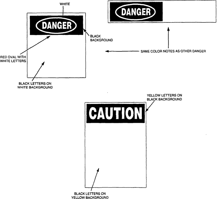
NOTE: The following are the preferred design and color principles for “SAFETY FIRST” (safety instructions) and “NOTICE” (product data information) labels/markings for the kinds of portable metal ladders cited in this standard. These labels/markings are illustrations of typical labels/markings and are not actual recommended size. The minimum recommended size is 2 inches × 8 inches.
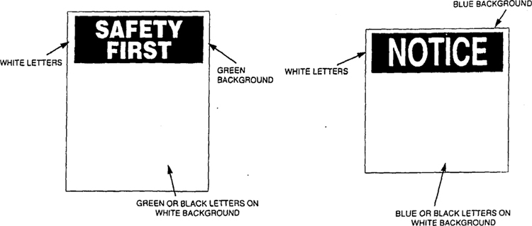
The preferred presentation is not mandatory, but if it is used, it should be used in the panel sequence illustrated in Marking No. 16. If necessary, elements may be rearranged, as multiple panel are used, However, any panel which includes the data of panel no. 1 should be shown with the word “NOTICE” as illustrated in Marking No. 16
The best method would be to present the notice and three panels as one label or marking. This method would mean the month and year date, for economic use of preprinted labels, would have to be entered by ink stamp for the one-label approach. Permanent inks should be sought — and are available — for such applications. in fact, if this information is stamped or burned, the rest of the marking can be a label or similarly stamped or burned, as long as the one-label effect is maintained.
The three panels are also designed to be divided between panels. no. 1 and 2 and panels no. 2 and 3. The notice and panel no. 1 should be presented as one unit either in a label or other marking, since this product information is most critical in selecting the right ladder. Such information provides the necessary elements of a sound purchase that allows the user to match his needs and requirements to the capabilities of the ladder.
Panel no. 2, if separated, may be stamped, burned, embossed, or otherwise marked, including a label which provides for ink stamping of month and year data. An effort should be made to avoid the placement of other markings between panels which are separated. In fact, the information in panel no. 2 may be placed elsewhere if it is first placed as required by 9.2. Additionally, the optional character of panel no. 3 may eliminate its use or incorporate its information in either panel no. 1 or 2.
Manufacturer′s and distributor′s name may be a logo. Manufacturing plant (if multi-plant organization) may be coded.
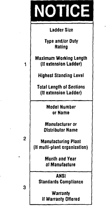
Marking No. 16 Preferred Notice Presentation
55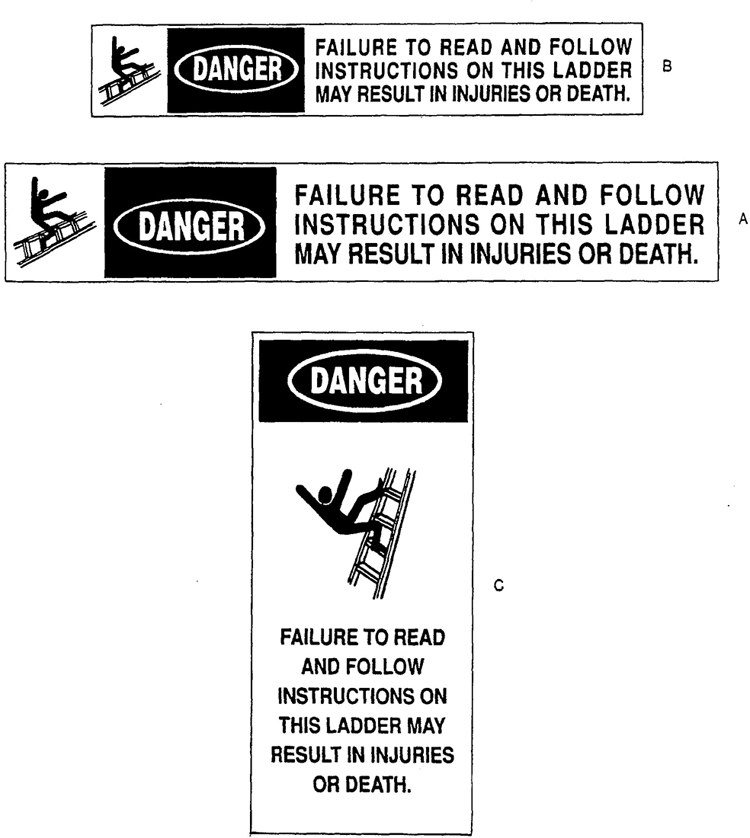
Marking No. 00
56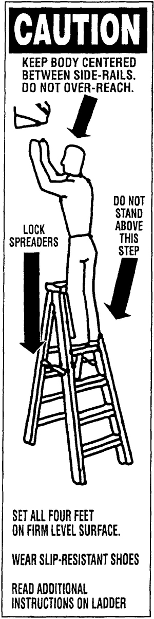
Marking No. 1
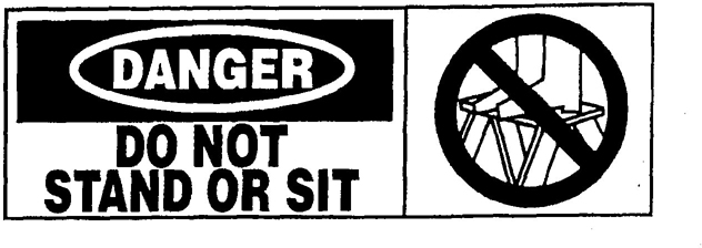
Marking No. 2

Marking No. 3
57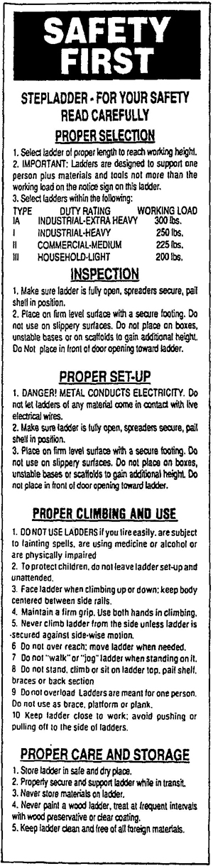
Marking No. 4
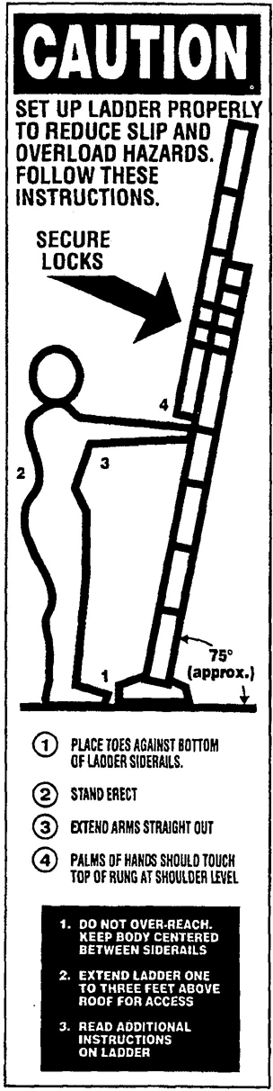
Marking No. 5

Marking No. 6

Marking No. 7
58
Marking No. 8

Marking No. 9
59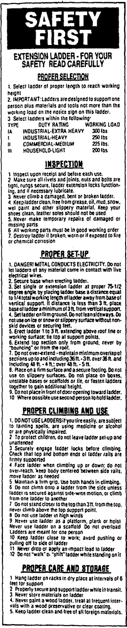
Marking No. 10
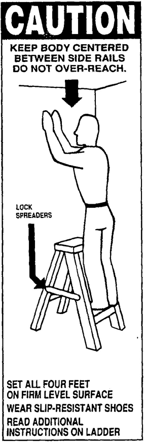
Marking No. 11
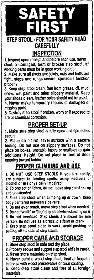
Marking No. 12
60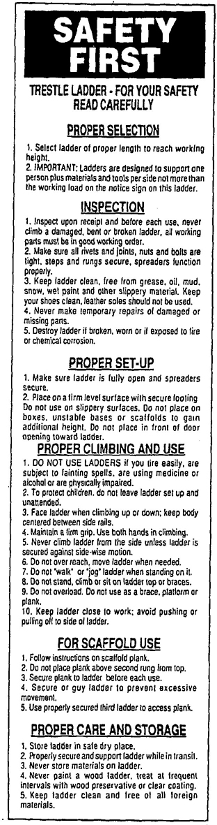
Marking No. 13
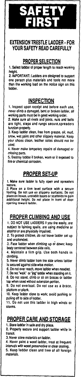
Marking No. 14
61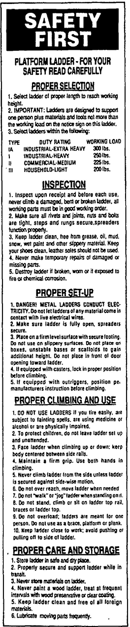
Marking No. 15
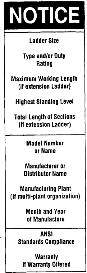
Marking No. 16
Illustrations courtesy of
Holly Label Co.
The following data gathering forms were developed by the A14 Testing Task Force to obtain meaningful information for validating and revalidating the ladder standard requirements. Having used the forms with remarkable success, the A14 Committee wished to share the beneficial results produced by the forms with the users of the ladders.
The ladder use survey basically provides a profile of ladder user habits, so that incorrect practices can be corrected by self instruction or be addressed in more formal training efforts. The second form, the bi-level injury report, is used to determine from the fall victim the various factors surrounding the injury. These forms can be used separately or together. since the survey questionnaire identified fall victims for later investigation.
These forms may be regarded merely as a starting point or framework. Modification of the basic forms to provide information more pertinent to a particular operation is also suggested. They are offered not only to assist in injury investigation, but to stimulate spin-offs or other, better investigative forms and tools to learn more about the causes of ladder injuries.
63LADDER USE SURVEY
I live in a(n)
______ apartment
______ condominium
______ home
______ one story
______ two stories
______ more than two stories
______ height
______ weight
______ age
______ sex
| Wooden: | Metal: | |
| Stepladder: | ______ size ______ age | ______ size ______ age |
| Extension ladder: | ______ size ______ age | ______ size ______ age |
| Combination ladder: | ______ size ______ age | ______ size ______ age |
STEPLADDER
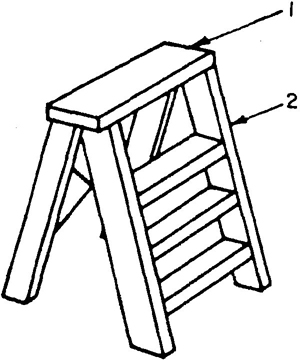
EXTENSION LADDER
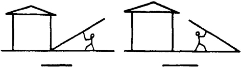
Other position, please sketch:
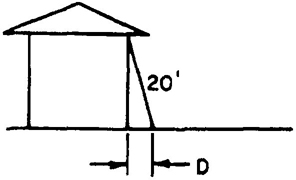
______ 3 feet
______ 4 feet
______ 5 feet
______ do not know
______ 6 feet
______ 7 feet
______ 8 feet
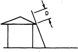
BI-LEVEL FALL VICTIM REPORT
This questionnaire is in five parts:
Part A – Personal Conditions at Time of Ladder Fall
Part B – Identification of Ladder Involved in Fall
| _____ Stepstool A = _____ feet |
_____ Stepladder B = _____ feet |
_____ Extension C = _____ feet |
_____ Straight D = _____ feet |
_____ Combination Indicate it used as stepladder or extension ladder and fill in appropriate dimension at left: _____ Stepladder _____ Extension |
 |
 |
 |
 |
Part C – Conditions of Site Where Fall Occurred:
| Yes | No | |
| Level | _____ | _____ |
| Uneven | _____ | _____ |
| Slippery | _____ | _____ |
| Hard | _____ | _____ |
| Soft | _____ | _____ |
Part D: – Activity of Climber at Time of Fall
1. What were you doing?
_____ Painting _____ Cleaning _____ Pruning _____ Storing
Working on: _____ Roof _____ Wall _____ Gutter
Other: _____________________
2. Height of work area (ceiling, shelf, window, tree branch, etc): _____ feet
3a. Stepladder:
When fall occurred I was:
_____ Climbing down
_____ Climbing up
_____ Standing
_____ Reaching up
_____ Reaching to the side
_____ Coming down to A from above
_____ Going up from A to above
Location on ladder:
_____ A
_____ B
_____ C
_____ D
_____ E
_____ F
_____ G
Stepladder closed, leaning against:
_____ Wall
_____ Tree
_____ Other
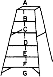
3b. Extension ladder:
When fall occurred I was:
_____ Climbing down
_____ Climbing up
_____ Standing
_____ Reaching up
_____ Reaching up the side
_____ Coming off roof
_____ Going on roof
Location on ladder:
_____ A
_____ B
_____ C
_____ D
_____ E
_____ F
_____ G
Extension ladder used as straight ladder:
_____ Taken apart
_____ Fully closed
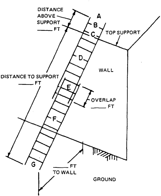
4. What appeared to happen at the time of the fall?
_____ Lost balance
_____ Step or rung broke
_____ Missed a step or rung
_____ Ladder collapsed
_____ Ladder tipped
_____ Electric shock
_____ Ladder slipped at top
_____ Extension lock failed
_____ Ladder slipped at bottom
_____ Wind blown
5. Personal assessment of the fall:
| Yes | No | |
| Was using the right ladder for the job | _____ | _____ |
| Placed the ladder correctly | _____ | _____ |
| Read labels and other literature | _____ | ____ |
| Personal condition was a factor | _____ | _____ |
Part E – Condition of ladder before and after fall
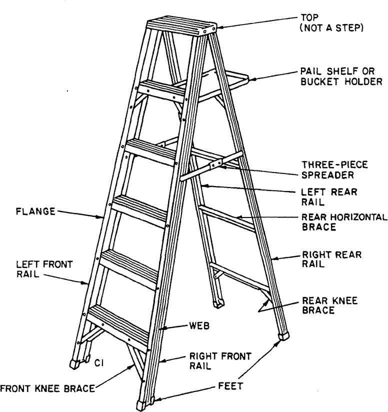
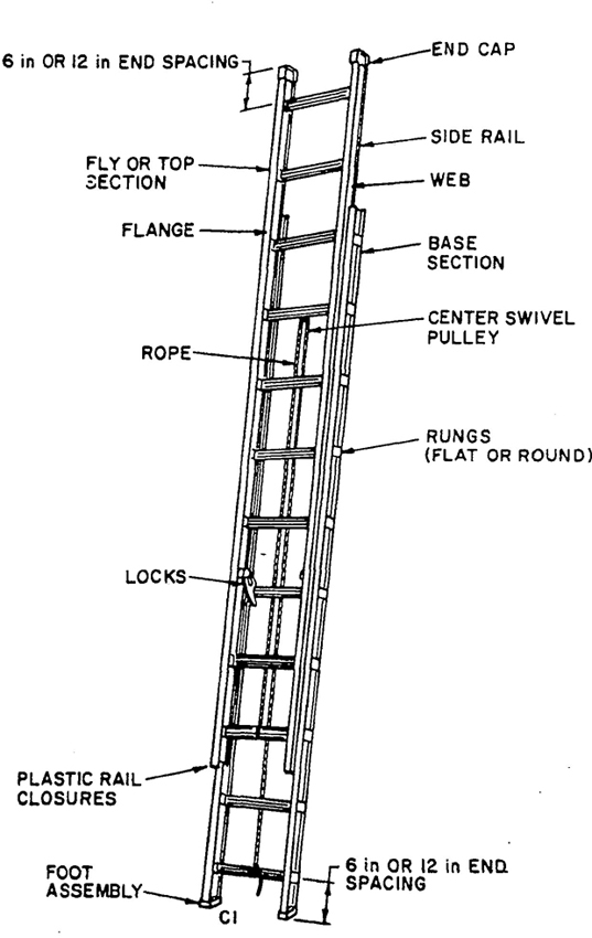
The standard in this book let is one of more than 10,000 standards approved to date by the American National Standards Institute.
The Standards Institute provides the machinery for creating voluntary standards. It serves to eliminate duplication of standards activities and to weld conflicting standards into single, nationally accepted standards under the designation “American National Standards.”
Each standard represents general agreement among maker, seller, and user groups as to the best current practice with regard to some specific problem. Thus the completed standards cut across the whole fabric of production, distribution, and consumption of goods and services. American National Standards, by reason of Institute procedures, reflect a national consensus of manufacturers, consumers, and scientific, technical, and professional organizations, and governmental agencies. The completed standards are used widely by industry and commerce and often by municipal, state, and federal governments.
The Standards Institute, under whose auspices this work is being done, is the United States clearinghouse and coordinating body for voluntary standards activity on the national level. It is a federation of trade associations, technical societies, professional groups, and consumer organizations. Some 1000 companies are affiliated with the Institute as company members.
The American National Standards Institute is the Untied States member of the International Organization for Standardization (ISO) and the International Electrotechnical Commission (IEC). Through these channels U.S. standards interests make their positions felt on the international level. American National Standards are on file in the libraries of the national standards bodies of more than 60 countries.
American National Standards Institute, Inc
1430 Broadway
New York, N.Y. 10018