881
Case No. 17,493.
29FED.CAS.—56
WHEELER v. CLIPPER MOWER, ETC., CO.
[10 Blatchf. 181; 6 Fish. Pat. Cas. 1; 2 O. G. 442; Merw. Pat. Inv. 242.]1
Circuit Court, S. D. New York.
Sept. 24, 1872.
PATENTS—INVENTION—REDUCTION TO PRACTICAL USE—REISSUES—COMBINATIONS—IMPROVEMENTS—INFRINGEMENT—EQUIVALENTS—HARVESTERS.
1. In order to sustain a patent for an invention, it is not necessary that the inventor should reduce the invention to practical use before he obtains the patent.
2. All that is necessary is that the invention should be perfected, and the proper specification, drawings and model be furnished.
3. A patent does not become void, if the patentee does not, after the patent is granted, put the invention into practical use.
4. A device which cannot be reduced to practical operation and use without the and of further invention, is not patentable; but it is not necessary to the patentability of a device, that it should have, in itself, apart from any connection with, or application to, other known devices or instrumentalities, capacity to produce practically useful results.
5. Where a patent claims a combination of several devices, it may be reissued to claim the devices separately, if new and useful, even though the aggregate combination claimed in the original patent was not, by itself, useful, or was even impracticable, provided the reissue points out how the devices separately claimed may be reduced to practical use.
[Cited in Calkins v. Bertrand, Case No. 2,317; Broadnax v. Central Stock-Yard & Transit Co., 4 Fed. 216. Approved in Odell v. Stout, 22 Fed. 163. Cited in Holmes Burglar-Alarm Tel. Co. v. Domestic Telegraph & Telephone Co., 42 Fed. 224.]
6. The right of a patentee to protection is not to be tested by the question, whether, in a state of the art subsequent to the granting of his patent, his invention, without improvement, would be deemed of value.
7. The reissued letters patent, Nos. 875, 877 and 879, granted to Cyrenus Wheeler, Jr., January 3d, 1860 (the original patent having been granted to him December 5th, 1854), and the reissued letters patent No. 2,610, granted to said Wheeler, May 14th, 1867, as a reissue of reissue No. 876, granted January 3d, 1860, of the same original patent, and the reissued letters patent, No. 2,632, granted to said Wheeler, May 28th, 1867 (the original patent having been granted to him February 6th, 1855), all for “improvements in grain and grass harvesters,” are valid.
[Cited in Aultman v. Holley, Case No. 656; Wheeler v. McCormick, Id. 17,499.]
8. Said original patent of 1854 is not open to the objection, that the machine described in it was not susceptible of reduction to practical use.
9. A machine cannot be pronounced useless or impracticable because it is susceptible of improvement which will obviate or prevent embarrassments to its most perfect operation.
[Cited in Gibbs v. Hoefner, 19 Fed. 324.]
10. The question of the infringement of the said patents, considered.
11. A patent for a device cannot be avoided by dividing the device into two-parts, which, when combined, produce the same result, in substantially the same way.
[Cited in Strobridge v. Lindsay, 6 Fed. 512; Westinghouse v. New York Air-Brake Co., 59 Fed. 597.]
12. A device is not less an equivalent of another, because, superadded to all the functions of such other, it may perform a further office, or, because, besides all the functions of such other, it performs some one of the offices more effectively, or better, so long as it performs them in substantially the same way, and uses substantially the same means.
13. A claim for devices described, which are alleged to produce a specified result, is not rendered invalid by proof that, under special circumstances, and on exceptional occasions, such result is not produced. The claim will be construed as describing the general rule of the operation of the device.
2 [Two suits. Final hearing on pleadings and proofs. Suits brought upon reissues of two letters patent granted Cyrenus Wheeler, Jr., for “improvements in grain and grass harvesters.” The first dated December 5, 1854, was reissued January 3, 1860, in five divisions, numbered respectively 875, 876, 877, 878, 879. Of these reissues, No. 876 was again reissued May 14, 1867, as No. 2,610. The second patent dated February 6, 1855, was reissued June 5, 1860, as No. 971, and again, May 28, 1867, as No. 2,632. The bill in the first suit alleged infringement of reissues Nos. 875, 2,610, and 2,632. The bill in the second suit alleged infringement of reissues Nos. 877 and 879.
[The defendants, in their answer, denied infringement; that the reissues were for the same inventions as the original patents; that 882the machine described in the original patent of 1854 was ever used, or was ever capable of successful use, and that Wheeler was the first and original inventor of the devices claimed; but alleged that the same were, prior to the date of Wheeler's invention, known to other persons, and described in various patents and rejected applications, and, among a large number of others, in the patent of Obed Hussey, December 31, 1833; the patent of William F. Ketchum, February 10, 1852, and the rejected application of Edwin P. Cavett, filed in 1852.
[The engraving, No. 1, is a sketch, representing the material parts of the drawing accompanying the original Wheeler patent of December 5, 1854, and will be readily understood when examined in connection with the specifications annexed.
[Specification of Wheeler patent of December 5, 1854: “Be it known, that I, Cyrenus Wheeler, Jr., of Poplar Ridge, in the town of Venice, county of Cayuga, and state of New York, have invented and made certain new and useful improvements on a machine for harvesting grain and grass, and I do hereby declare that the following is a full and exact description of the construction and operation of the same, reference being had to the accompanying drawings making part of this 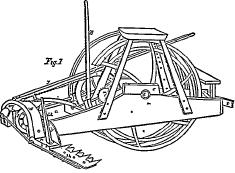 specification, in which—Fig. 1 is a perspective view of the machine. Fig. 2, of the arched bar and half of joint. Fig. 3, of socket, standard, quadrant, and corresponding half of joint. Figs. 4 and 5, longitudinal sections of cutter-bar or arm, with knife or cutter and spring. Fig. 6, cutter-spring. Fig. 7, perspective view of table or apron for holding the grain a are the side pieces of the frame attached to the shaft, b, of the driving-wheel by boxes, c, in which the shaft revolves. The side-pieces, a, extend forward of the driving-wheel, d, sufficient distance to attach a tongue by a roller, e, which admits of the tongue moving freely up or down, thereby enabling the machine to adjust itself freely to the inequalities of the ground. The side-pieces, a, extend back from the driving-wheel sufficient distance to admit of a cross-piece, f, and to give sufficient space for the caster-wheel, g, to move freely on its spindle, h, between the cross-piece and the connecting-rod i. d is the driving-wheel of the machine, which is firmly attached to the shaft b. j is a rim attached to the inside of the arms, k, of the driving-wheel, d, and having cogs, l, on its internal surface, which gear into a pinion, m, which pinion is attached to a shaft, n, on which is also fastened a face-wheel, o, which face-wheel gears into the pinion, p, which pinion is firmly attached to the shaft, q, at one end, and at the other is attached to a wheel, r, in which is inserted a wrist, which serves as a crank. The shafts, n and g, are supported by boxes attached to the frame-work, in which they freely revolve; to is a wheel of the same size as the driving-wheel, and is attached to the shaft, b; which projects sufficiently far through the side-piece, a, to admit of the wheel's revolving freely outside of the framework. The wheel revolves freely on the shaft, as its axle, without interfering with the motion of the driving-wheel, while it serves to keep the machine in an upright position; u is the driver's seat, elevated above the driving-wheel, and supported by its legs, v; w is an arched bar passing over and on the outside of the, hinder part of the side-pieces of the frame, a, to which it is attached by bolts, x, passing through both, and admitting of the top of the arch, w, being turned backward or forward as on hinges or pivots by the lever, y, which is firmly bolted to the top of the arch, w, and extends forward on the inside of the driving-wheel to the inside forward leg, v, to which it is secured by a guide and pins, z is a socket with the half of a rule-joint, a, a, attached to its corresponding half at the end of the arched bar, w, by a bolt passing through both; b, b, is a quadrant attached firmly to the inner side of the socket, z, and passes by and close to a similar one, c, c, attached to the end side of the arched bar, w, thereby strengthening and supporting the joint, a, a; d, d, is a standard, firmly attached at its base or lower end to the socket, z, and at its upper end is perforated with a hole, to which is attached a chain or rope, e, e, which parses around the pulley, f, f, on the top of the arched bar, w, and is carried forward to the lever, g, g, which lever is attached at its lower end by a bolt to the middle piece, s, s, of the frame, admitting of the upper end of the lever being moved backward or forward; h, h, cutter-bar, composed of an upper and lower portion, with sufficient space left between for the admission of the knives or cutters, i, i, and a spring, o, o, between the knife or cutter and the bed-piece or lower half of the cutter-bar, h, h. j, j, points of the stationary or upper portion of the cutters; k, k, bolts passing through both parts of the cutter-bar, h, h, and through the knives or cutters, i, i, and through the spring, o, o, the knives or cutters, i, i, moving on the bolts, k, k, as on a pivot. The shanks of the cutters, i, i, extend back of the bar, h, h, far enough to admit 883of attaching the driving-rod, 1,1, to them by bolts or pins; i is a connecting-rod composed of two parts, with a screw admitting of its being lengthened or shortened at pleasure. One end of the rod is attached to the driving-rod, 1, I, by a joint, and the other to the crank or wrist, s; g is a caster-wheel; h is a spindle and straps or legs which support the wheel, the spindle passing through the arm, r, r, which arm is bolted at the other end firmly to the cross-piece, f.
[“Figs. 2 and 3 are detached views of the arm and socket when united at m, m, by a bolt A strong joint is made similar to a rule-joint, which admits of the outer end of the cutter-bar, h, h, rising or falling with the inequalities of ground when in use. The arch, w, is united to the hind part of the side-pieces, a, by bolts at x, which admits of the top of the arch being rolled on the bolts backward or forward. Figs. 4 and 5 are longitudinal sections of the cutter-bar—Fig. 4 being a representation of the upper surface of the under half or portion of the bar, and fig. 5, the under part of the upper portion or half of the bar. The points or stationary cutters, j, j, are made concave on their under side, for the purpose of giving a better fit to the cutting edges of the movable cutters or knives, i, i, which knives have a concave surface on their upper part, from their point to a short distance back of the bolts on which they turn, n, n, show the upper portion of the guards or braces, which guards are fastened to the under side of the under portion or half of the cutter-bar, and are curved upward and meet the points of the upper or stationary cutters, to which they are united by rivets or screws, sufficient space being left between the two for the free play of the movable cutters, o, o, represent a curved spring of steel, with a hole through the middle for the admission of the bolt on which the movable cutter turns. At one end of the spring, o, o, is a slot, p, p, which serves, by means of a pin in the lower part of the cutter-bar, to keep the spring o, o, in position. The spring, o, o, by its form and position under the movable cutter, i, i, serves to press the upper or cutting-edge firmly against the under surface of the upper portion of the cutter-bar, h, h, and its stationary points or cutters, j, j. The Figs. 4 and 5, when united at each end by bolts or rivets, sufficient-space being left between the two for inserting the knife or cutter and spring, forms the cutter-bar, which is firmly bolted to the socket, z, by bolts passing through the hole, q, q, and corresponding holes, g, g, in the socket, z. The cutters, i, i, are beveled from the upper edges downward and inward, making a sharp shear-edge on both sides. The upper or stationary cutters or points, j, j, are beveled upward and inward, so as to present a sharp corner for the movable cutter to operate against. Fig. 7 is a representation of the table or apron for receiving the grain when cut, and bolts or fastens to the under side of the cutter-bar, h, h. The cutter-bar h, h, is composed of two bars of Iron of similar width and thickness, bolted or riveted together, with their flat surfaces parallel to each other, a space being left between them by inserting blocks or pieces of metal, and the stationary cutter may be welded to the upper bar, or fastened to it by rivets or bolts. The wheel, t, being constructed partly of wood and partly of iron, or wholly of iron, and so fitted to the shaft as to play freely on it, as its axle, without interfering with the motion of the driving-wheel, the face-wheel, o, and the pinions, m, and p, should be of such size, as, combined with the driving-wheel, d, will give from twenty-five to thirty revolutions of the crank or wrist, s, to one of the driving-wheel. The crank-shaft, g, should be of sufficient length to bring the crank or wrist, s, in direct line with driving-rod, 1, 1. The arched bar, w, should be composed of iron. The ends of the arched bar, w, on its inside, should be made straight, and parallel to each other. The spring is bent in a curved or arched form, o, o, so the ends of the spring may rest on the lower part of the cutter-bar, h, h, and the center of the spring press against the under portion of the knife or cutter, i, i. I also fasten to the top of the arch, w, a lever, y, of iron or wood, which extends forward and passes through a guide attached to the inside forward leg, v, and is confined, at any required height, by pins passing through the guide and leg. The caster-wheel, g, is composed of iron, from ten to sixteen inches in diameter, with a rim from two to three inches wide, which is placed in a strong stand or legs of, with a spindle, h, attached, which spindle passes through an arm or socket, r, r. The arm or socket, r, r, is composed of iron of a curved form, and of sufficient length to admit the caster-wheel, g, playing freely on its spindle under it, without interfering with the cross-piece, f, to which the arm is firmly bolted. The apron or grain-table is composed of a light framework, covered with boards, which may be made to correspond in length to the cutting portion of the cutter-bar, h, h, and may be fastened to the cutter-bar, when desired, by bolts—the width of the table being made sufficient to catch the falling grain, which may be raked from it by a man riding on the machine. In operating the machine the off-horse travels near the standing grass. The movable cutters, i, i, by their position under the stationary points or cutters, j, j, and by being firmly pressed against the corners or edges of them by the springs, o, o, as they move to and from their bolts in the are of a circle, cut freely and easily all grass or herbage coming between the points and cutters—the machine cutting equally well the coarsest or finest and softest grass, not being liable to clog or buff in thick fine herbage, and cutting equally well at the fastest or slowest walk of the team, the arched bar and socket being supported and kept from pressing too hard upon the ground by the caster-wheel, g. The caster-wheel also, by its support, admits of the machine being 884turned short round, avoiding the necessity of backing the team when coming out, and setting it at the corners of the standing grass. The cutter-bar, h, h, in the movement of the machine forward, rises and falls beyond the joint, a, a, adjusting itself to the inequalities of the ground. By the lever, y, attached to the arch, w, the driver can raise or depress the points of the cutters, i, i, and j, j, the arch, w, turning on its bolt, x, as on a hinge, for the purpose of cutting off higher or lower, or for the purpose of passing any obstruction met with, without leaving his seat; and in like manner can, by the and of the perpendicular lever, g, g, and its connections, the chain, e, e, the pulley, f, f, and the standard, d, d, raise the outer end of the cutter-bar h, h, to any required height, and sustain it there, for the purpose of passing obstructions, or for the convenience of moving from one field or place of operation to another. Having thus fully described my improved machine, I would state that I do not claim the driving-wheel, face-wheel, or pinions, the boxes or shafts of the same. Neither do I claim the connecting-rod of two parts, or the driving-bar, nor claim the double-edged movable pivoted cutters, or shears as pivoted in the center, and placed on the top of the stationary or fixed ones, or the cutter-bar as heretofore constructed by others. Neither do I claim the seat for the driver, or the table for receiving the grain. I do not claim the caster-wheel, as such alone, but, what I do claim as my invention, and desire to secure by letters patent, is: The hanging the cutter-bar, h, h, provided for the purpose, with a socket, z, to one extremity of the arched bar, w, by means of joints, a, a, and segments, b, b, c, c, said arch bar, being in its turn pivoted in x, to the main frame, a, a, all for the purpose of giving the cutter-bar, h, h, by means of levers y, d, d, and g, g, a motion independent of the frame, and both rotating longitudinally parallel to the ground, and oscillating radially from the joints, a, a, in order to adapt the same to the inequalities of the ground, or to stop its action at pleasure, as described.
“Cyrenus Wheeler, Jr.”
[The first division of the reissue No. 875 related principally to the “hinged shoe, M,” and its combinations. It contained the following general description: “In the construction of a grain and grass harvester known as a ‘combined reaper and mower,’ there are many essential features that must be adaptable to both reaping and mowing, the condition of each operation varying with the material to be cut, and the nature of the ground over which the machine is to be operated. In cutting grain, the cutters are raised a considerable distance above the ground, but in this position they must be under the easy control of the driver or operator; whilst in cutting grass, it is important that the cutter should run as close to the ground as possible, having due regard to their security from striking into or against any intervening obstacles. To make a mowing machine practical, the cutter-bar should follow the undulations of the ground over which it passes, without being influenced by the inequalities of the ground over which the wheel or wheels of the main frame may be passing, and to make it thus follow the undulations of the ground, it should depend upon receiving all its vertical movements from the surface of the ground over which it is, for the time being, passing, whilst its forward movement only is controlled by the main frame. To construct such a convertible machine as will adapt itself to both the cutting of grain and grass, and be susceptible of the necessary adjustments for each separate purpose, constitutes the general characteristics of this invention. And the manner in which the machine is constructed, will be hereafter fully set forth, first premising that there are certain principles or functions in the organization of the machine which form the subject-matter of separate applications for letters patent, whilst this application looks to the construction of the details or devices by which these more general principles are carried out, and the manner in which I have combined and arranged them in one machine, to effect the several purposes hereinafter mentioned.”
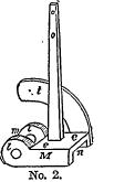
[It contained also the following description of the “hinged shoe, M.” which will be readily understood when read in connection with the engraving No. 2, a facsimile of Fig. 3 of the reissue: “To the rear portion of the main frame is connected an arm, K, which carries a caster-wheel, L, by means of which said rear portion of the frame is mainly supported, and may be raised, and held up if desired; the piece, H, and the shoe or socket, M, connected to it, are also supported and kept from pressing too hard upon the ground by the caster-wheel, I, which may, by washers No. 2. placed on the spindle, be made to support these parts at any given height. The shoe, M, is hinged to the piece, H, by a pivot-bolt, k, which stands at right angles to the pivots, i, of the brace,” bar, or piece, H, so that the shoe, M, and consequently the finger-bar that is connected to it, as will be hereafter explained, may have the motions incident to both the hinged or pivoted points, i and k. The shoe, M, as more distinctly seen at Fig. 3, has lugs, 1, 1, and space m, between them, into which the end of the hinged piece, H, passes, and by means of the pivot-bolt, k, passing through their holes, the hinge is formed; it has also a socket or recess, n, made in it, for receiving the end of the finger-bar, in (Fig. 7), said finger-bar being firmly bolted to said shoe by bolts passing through their respective holes, o, o, 6, 6 therein. To the shoe, M, is connected a post 885or arm, O, to the upper end of which is fastened a rope or chain, p, which passes around a friction-pulley, g, on the piece, H, and thence to a lever, P, to which it is adjusted and fastened.”
[The claims of this reissue were as follows: “I claim under this patent, first, in combination with the hinged-bar, H, and the finger-bar, the intermediate shoe, M, hinged to said bar, H, substantially in the manner and for the purpose set forth. I also claim, in combination with the hinged-bar, H, a lever that, when released, allows said bar to freely-swing around its pivoted points, and when fastened, holds said bar firmly in its adjusted position, as described. I also claim the shoe, M, as a hinge and support both, to the cutter-bar, substantially as described. I also claim the socket or recess, n, in the shoe, M, for the reception of the finger-bar substantially as described. I also claim, in combination with a finger-bar hinged at one of its ends to an intermediate piece, also hinged to the main frame, an elevating and supporting caster-wheel for carrying that end of the machine when adjusted for reaping or mowing, substantially as described. I also claim the combination of a brace or support, t, on the shoe, and a similar brace or support, u, on the bar, H, for resisting the strain on the finger-bar, when reaping, substantially as described, or for transporting it from place to place. I also claim the flexible connection for elevating the outer end of the finger-bar, substantially as described.”
[Reissue No. 2,610 was for the finger-bar. [It contained the following general description: “To adapt a harvesting machine to the mowing of grass, it is necessary that the finger and cutter-bar should travel close to the ground, and not only this, but that they should receive all their vertical movements from the ground over which they pass, and not be influenced by the projections or depressions over which the driving wheel or wheels are passing. But as the finger and cutter-bar must receive their advancing movement from the main frame, its organization, and connection of the cutter therewith must be such as to allow the finger-beam to have a free vertical movement both above and below the plane over which the driving-wheel is passing. The object of this invention is to cause the finger-beam to conform to the undulations of the ground independently of the movement of the driving-wheels, and this is accomplished by employing a frame which vibrates about the axis of the driving-wheels, and attaching the finger-bar to one corner thereof, and attaching the draught to the frame by means of a loose or hinged connection. The gearing which drives the cutter is so arranged about the axis of the drive-wheels as a driving-center that, as the corner of the frame to which the finger-bar is attached, rises and falls, the driving of the cutter is not disturbed. The finger-bar is attached to this vibrating frame at one corner by a hinge. The propulsion of the finger-bar forward is effected solely by this hinge. Thus, while the vibrating frame permits the finger-bar attached to its corner to follow the ground, the hinge propels the finger-bar, and permits its outer end to rise on said hinge, and thus a floating finger-beam is produced. The gearing consists of a beveled wheel on a shaft extending from the inner side of a rim attached to the driving-wheel to the beveled wheel on one end of the crank-shaft, by which the cutter is vibrated, and thus the cutter vibrates without disturbing the relative position of these driving parts.”
[The claim was as follows: “I claim, in combination with a harvester-frame that is free to vibrate about a gear-center, a laterally projecting finger-bar, so hinged to one end or corner of said frame, as to permit the finger-bar at each end to follow the undulations of the ground over which it is drawn.”
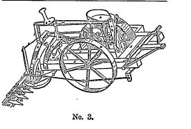
[The claims of reissues 877 and 879 will be found in the opinion of the court. The second patent, granted February 6, 1855, was applied for in September, 1854, while the first was still pending. Engraving No. 3 is a sketch of the patent office model, filed with this second application.
[The disclaimer and claims of this patent were as follows: “Having thus fully set forth my improvements in the foregoing description, I will proceed to state my claim. In the first place, I do not claim the framework, a (Fig. 1), the driving-wheel, b, its cogged rim, e, shaft, d, pinion, f, face-wheel, g, shaft, h, pinion, i, shaft, j, crank-wheel, k, driver's seat, z, raker's seat, y, connecting-rod, g. Neither do I, in this, intend to disclaim the screw, i, i, nuts, o, o, arched bar, 1, and its pivotal attachment, a, b, the joint, m, quadrants, n, socket, o, standard, p, caster-wheel, r, spindle, s, rod and chain, t, pulley, u, lever, v, bail, h, h, having previously invented them or their equivalents, which are fully set forth and described in a caveat and drawings filed by me in the patent office, on or about November 28, 1853, and still further described in a specification, model, and drawings filed in the same office on or about March 16, 1854. But what I do
886
claim, and desire to secure by letters patent, is: I claim the combination of the double-edged cutters, r, r (Fig. 1), with the cutter-bar, x, s, the braces, z, z, the vibrating cutters, 1, 1, their shanks, m, m, projections, u, u, the circular ribs, t, t, the bolts, p, p, the spring, a (Fig. 3), the holes, g, g (Fig. 1), the ribs & (Fig. 3), the cavities, y, y (Fig 1). or their equivalents, as substantially set forth, the whole forming the cutting apparatus of the machine. 2. I claim the revolving or track rake, consisting of its frame, 1 (Fig. 1), its wheel, 3, shaft, 4, pinions, 7 and 10, shaft, 6, wheel, 5, teeth, 8, apron, 2, joint, 9, and cap, 11, or their equivalents, arranged and combined substantially as set forth.”
[This patent was twice reissued; the sec-time as No. 2,636. This reissue contained the following general description: “My invention relates to that class of machines known as ‘combined machines'; that is to say, harvesting machines capable of cutting grass or grain either, and that can be changed from one to ‘the other purpose conveniently. When cutting grass, the machine should follow as closely as possible the undulations of the ground; but when cutting grain, it should carry its cutting apparatus above the surface of the ground. To make a machine equally adaptable to both these purposes, requires that it should have two properties that would seem inconsistent with each other in one machine, viz: the property of adapting itself to the surface of the ground over which it is passing while cutting grass, in which case the several parts of the machine must have motions independent of each other; and, secondly, the property of being elevated above the ground and held comparatively rigid in such elevated position when cutting grain; but in both conditions to be under the control of the driver or conductor, who, from his seat, can elevate or depress such portions of the machine as may require it for passing obstructions, or for cutting at a greater or less height above the surface of the ground. In changing such a machine, to convert it from a grain-cutting to a grass-cutting machine, or vice versa, some of its parts must also be changed; and my invention relates to some of these parts, also, as will be hereafter set forth, as they perform certain functions important in their particular relations and conditions. Such are the general purposes and objects of my invention. Their specialties will be more fully set forth hereafter, as well as the several mechanical devices which I have contrived for turning the machine short around at the end of the swath, for strengthening the finger-bar when cutting grain, and making it lighter for cutting grass, and for a track-clearer. My invention consists in so combining a finger-bar with the main frame of a harvesting-machine, and with levers, or their equivalent raising or lowering devices, extending to within reaching distance of the driver or conductor in his seat, as that said driver or conductor from his seat may raise up either end of the finger or cutter-bar, independently of the other end, or both ends at once, at pleasure; and my invention further consists in the use of a platform, which, when the table or platform is used, is attached to the finger-bar, and removing the platform when the machine is converted into a mower; and my invention further consists in combining with the platform or table a caster-wheel, so hung that when the machine is being turned around, said caster-wheel will elevate the platform, and also the outer end of the finger-bar, and thus prevent them from striking against any projection, or being wrenched, strained, or broken; and, in connection with the platform caster-wheel, the caster-wheel in the rear end of the main frame, when they bear the relative position substantially as they do to the finger-beam and main wheel, as represented; and my invention further consists in a track-clearer, that is caused to revolve by gearing, and so located that in backing the machine, or turning it around, there will be no danger of breaking or otherwise injuring said track-clearer.”
[The claims were as follows: “1. The combination of a vibrating frame, a finger-bar attached to one corner or end thereof by a hinge, and a platform in rear of said finger-bar, so as to leave an unobstructed space for the delivery of the grain onto the ground. 2. The combination of a vibrating frame, with the cutting apparatus hinged thereto, a driver's seat, and an arrangement of one or more levers, whereby the driver, in his seat, can raise and sustain the cutting apparatus when desired. 3. The combination of a finger-bar, hinged to a vibrating frame, and a removable platform connected with the said frame by means of the finger-bar only. 4. The combination of a hinged finger-beam and a side-delivery platform, so arranged that the grain may be delivered from the platform onto the ground out of the way of the horses on their next round. 5. The combination of a hinged finger-beam, a lever and a yielding or linked connection, extending from the lever to the vibrating part of the machine to which the finger-beam is attached, whereby the inner end of the finger-beam is raised to pass obstacles in mowing, and raised and sustained in reaping. 6. The combination of a hinged finger-beam, a lever, a yielding or linked connection extending from the lever to the vibrating part of the machine to which the finger-beam is attached, and the seat for the driver, whereby the driver can raise the inner end of the finger-beam to pass obstacles in mowing, and raise and sustain the same in reaping. 7. The combination of a hinged finger-beam with an auxiliary draught-rod or bar attached to the inner end of the hinged finger-bar. 8. The platform-bar, Q, as a means of securing the platform to the finger-beam, and for strengthening said finger-beam when it has the platform to carry, substantially as described. 9. The inclined caster-wheel, S, arranged as represented, and in combination 887with the platform, whereby the latter is elevated when the machine is being turned short around to the right, substantially as described. 10. In combination with a finger-beam and platform, placed in rear of the main supporting-wheel, the two casters, N, S, arranged as described, for allowing the machine to turn short around to the right, for the purposes specified. 11. A revolving track-clearer, when operated from a ground-wheel through gearing, substantially as described.”
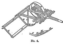
[Engraving No. 4 is a fac-simile of the drawing of the W. F. Ketchum patent of February 10, 1852. This, and the patent granted E. B. Forbush, July 20, 1852, referred to by defendants as anticipating the first, third, and fourth claims of reissue No. 875, showed two forms of the socketed shoe. They were prior in date to Wheeler's “shoe M,” but were attached rigidly to the machine, while Wheeler's was hinged Both showed a socket for 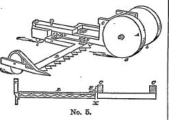 the finger-bar. Engraving No. 5 is a sketch of the model of the Hussey machine, patented in 1833, and introduced by defendants as an anticipation of the claim of reissue 2,610, as showing a hinged finger-bar. The rejected application of Cavett, filed in April, 1852, and introduced by defendants as an anticipation of reissue 2,610, showed a rocking frame, and a cutter-bar hinged to a comer thereof. It was, however, claimed by complainant that the rocking frame did not vibrate about a gear-center, and that the device was never used. It was also argued that it was at best a rejected application, and that, under the law, a rejected application can not be received to defeat the validity of a subsequent patent.
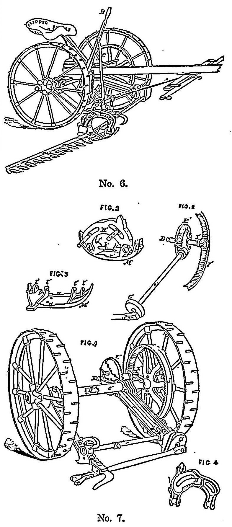
[Engravings Nos. 6 and 7 represent the Clipper machine, as made and sold by the defendants. Its construction will be readily understood from the engravings, when examined in connection with the opinion of the court.]2
George Harding, for complainant.
S. D. Law, David Wright, and B. F. Thurston, for defendant.
WOODRUFF, Circuit Judge. These suits are prosecuted for the alleged infringement of patents granted to the complainant, and seek an injunction and an account of the income derived by the defendant from such infringement. The patents in question are for improvements in grass and grain harvesters. The first original patent was granted December 5th, 1854, on an application filed March 88816th, 1854, and is numbered 12,044. This patent was surrendered in November, 1859, and reissues were granted for several separate and distinct parts of the improvements claimed to be embraced in the original patent, and such reissues were dated January 3d, 1860, and numbered 875, 876, 877, 878, and 879. Of these reissues, one, No. 876, was again reissued May 14th, 1867, and numbered 2,610. The second original patent was applied for September 20th, 1854, and was granted on the 6th of February, 1855, and numbered 12,367. This patent was also surrendered, and, on the 28th of May, 1867, was reissued, numbered 2,632. These suits are brought upon the said two original patents, as reissued under the numbers 875, 877, 879, 2,610, and 2,632. The bill in the first suit alleges infringement of reissues 875, 2,610 and 2,632; and the bill in the second suit alleges infringement of reissues 877 and 879. The answers in each suit are substantially the same, the proofs taken in each, so far as pertinent or applicable to each, are the same, and the suits were brought to a hearing and argued together.
The defendant insists upon the invalidity of the complainant's reissued patents, upon want of novelty in the distinguishing features of the complainant's alleged invention and upon a denial that the defendant has infringed the patents in any particular in respect to which the complainant's patents can be sustained, if sustained at all. My examination of the patents and of the proofs has led me to a different conclusion upon all of these grounds of defence. I shall not probably find time to write in detail my analysis of the patents, discuss the particular proofs, and give the reasoning which brings me to the result. I should be pleased to do all this, and it would be of some convenience to counsel on the review which, I assume, cases of so much importance will hereafter receive. But, other cases require my attention, and I shall do little more than indicate my opinion on the points chiefly argued by the counsel.
(1) The first ground upon which the complainant's reissued patents are assailed is, that the original patent of December 5th, 1854, was void, for two reasons: 1st. That the invention therein mentioned was never reduced to practical use; and, 2d. That the machine, as described and shown in the original record, was not susceptible of being reduced to practical operation.
On the argument, it was insisted, that a patent is void, if the patentee did not reduce the invention to practical use before the patent was obtained. This proposition is wholly unsound. No such condition is required by the act of congress; and, if it were true that a patent would be void on that ground, no patent could properly be granted, unless proof was furnished that the invention claimed had gone into practical use, which is not and cannot, under the statute, be made a condition of granting the patent. It is enough, that the inventor has perfected his invention, and is able to furnish to the patent office such specifications and model as the law requires. Having done this, the patent, in so far as prerequisites to its validity, either by way of experiment or use, are material, is valid.3
But, the terms of the brief before me are, that the “patent of December 5th, 1854,” was void, because it was never reduced to practical use.” This includes, perhaps, the idea, that the patent became and is now void, and was void when it was surrendered and reissued in several divisions, as above stated, because the invention described therein has never, since the patent was granted, been put into practical use. This is an argument, not that the patent was originally void, but that, through the neglect of the inventor, it has become invalid. It involves the idea of abandonment of the invention. The statute requires that an alien shall put, and continue, on sale to the public the invention or discovery for which he receives a patent, but it contains no such provision in relation to the patentee, when a citizen of the United States. If an invention is not so far perfected as to be adapted to use, that is to say, where the invention is of a machine, or part of a machine, and is not so far completed, that, when constructed, it will produce the desired effect, then, indeed, no patentable invention has been made. But, if the invention be such, that, when the thing invented shall be constructed according to the model and specifications filed, it will operate successfully as a practical and useful thing, the inventor has satisfied the law, and his patent is valid. He is not bound, by law, to construct it, in order to preserve his patent.
(2) This leads to the second of the defendant's reasons for insisting that the patent of December 5th, 1854, is void, namely, that the machine, as described and shown in the original record of the patent, was not susceptible of being reduced to practical operation. If, by this, is simply meant, that a machine, or a device, that cannot be reduced to practical operation and use without the aid of further invention, is not patentable, there is no occasion here for calling it in question. On the other hand, if it be meant, that no device is patentable which has not in itself, apart from any connection with, or application to, other known devices or instrumentalities, capacity to produce practically useful results, then the proposition is not true. 889 Patents for simple devices, and patents for parts of machines, are almost numberless, of which it may be truly said, that it is only by connection with other devices or instrumentalities, to which they are intended to be applied, that they can be made to produce any result whatever. True, the patentee is bound to disclose a mode in which they may be rendered practically useful, and it may be one of many modes, and it may necessarily involve the use of many other known devices which are required in order to the useful result. Patents may be granted for combinations, in which some of the parts are old and some are new, and whatever in the several parts is new may be separately secured to the inventor; and yet it may be true, that only in the combination described, or in some similar combination, is the new part thus secured to the inventor of any practical use whatever.
(3) This brings into view the defendant's claim, that the several reissues of the original patent of 1854 are void, because they are not for the same invention as that described in the original patent record. The original patent embraced, as an aggregate combination, several parts of the entire machine described in the specification, and claimed such aggregate as the invention of the complainant These parts were all shown in the specification, drawings and models. I know of no rule which forbids the inventor, who has omitted to claim separate new devices, or severable and distinct combinations, In the original patent, making a surrender, and taking reissues for the distinct combinations or separate devices. From the fact of surrender and reissue, it is to be inferred, that the original patent did not secure to the patentee all that he claims in the reissue; but, that alone does not render the reissue void. If the devices covered by the reissues were, in fact, new and useful, and if they are shown in the original specification, drawings, or model, then the patentee is entitled to secure the exclusive use of each separately, by a reissue embracing each.
Again. The claim that the original patent of 1854 was void because the invention therein described was not susceptible of being reduced to practical operation, gains its importance to this controversy from the inference sought to be drawn therefrom, namely, that the several reissues are, therefore, void. These suits are not founded on the original patent, but on the reissues; and the claim is, that, if the original patent was void, because the machine therein described was not capable of reduction to practical use, therefore, the reissues are themselves void. If the premise were here conceded, I do not think that the inference necessarily follows. For example—suppose an inventor of several distinct new devices, or of several new combinations, each capable of being usefully employed in and towards a machine or various machines, and that their separate construction and mode of operation is fully apprehended, and the distinct office or function of each is appreciated—such inventor may, undoubtedly, have a patent for each. Suppose, now, he erroneously conceives that he has arranged a combination of all of them, or a combination of all of them with other known devices, so as to produce a new and useful machine, and for such a machine he applied for and obtains a patent, describing and illustrating all the several new devices, or separate combinations of devices, their construction, and operation, but claiming only the aggregate machine. Such aggregate machine may be utterly useless; the patentee is wholly mistaken in regard to the practical operation of the whole; it will not produce the result for which it was intended, nor, in its aggregate form, any other useful result. Does the inventor, in such case, lose the benefit of his skill and ingenuity in producing devices, or combinations of devices, which are of practical value, because he first sought his patent in the form of a useless or impracticable combination? I apprehend not. He may surrender his original patent, and have it reissued in parts, which shall claim the respective new and useful devices or combinations of devices, pointing out, of course, in his specification, some mode or manner in which they may be reduced to practical use and value. He might have done this in his original patent, and claimed each separate new device as his invention. Not having done so, he may do so in his application for reissues and his specifications therein; and the fact, if it be true, that his original patent was defective, because he claimed therein the aggregate combination, and that a useless or impracticable one, no more impairs the validity of the reissues, than any other defect or invalidity which makes a surrender and reissue necessary to protect the device or devices which are useful, and which were in fact invented.
These observations upon some of the legal grounds upon which the complainant's patents are assailed, are made in order to exclude the idea that they are assented to, and not because I find, as a fact proved in the cause, that the machine described in the patent of December 5th, 1854, was not a practical and, within the meaning of the law of patents, a useful machine. I find the contrary. Doubtless, when viewed in the light of subsequent improvements, it was imperfect, but it was a very large advance upon machines for mowing theretofore attempted. It is one of the embarrassments to which early inventors are constantly subjected, that other persons, availing themselves of the substance of the invention, make improvements thereon, which measurably hide the merit of the original; and, if the right of a patentee to protection were to be tested by the question, whether, in the present state of the arts, his invention (without improvement) would be deemed of any value, or be saleable 890for use, very many authors of most important inventions would be turned out of court.
(4) The principal ground upon which it is claimed, and attempted to be proved, that the machine, as described and claimed in the original patent of December, 1854, was not susceptible of reduction to practical use, is, that the socketted piece receiving and holding the finger-bar, (or cutter-bar,) at the inner end, though called a shoe, m, in the re-issued patents, was not a shoe in fact—it had no toe; and it is, therefore, said, that, if it encountered an obstruction in its path, it would not slide over it, but must stop the machine, or the cutter-bar be wrenched from its connection with the frame; and, further, as the rear of the supporting-frame was described as resting on a caster-wheel, midway the sides of the frame, in the line of the cutter-bar, it is certain, that, whenever the caster-wheel passed into a depression in the ground, existing only in its own line of travel, this socket-piece, misnamed a shoe, would come to the ground, and, for want of the curved toe, would plough into the ground, and stop the machine, or wrench the bar, as in the other case.
Now, in the first place, the socket-piece holding and supporting the inner end of the cutter-bar, is, in fact, shown to have its under surface curved or rounded up at its front. It is so shown in the model furnished, before the patent was granted, on the requirement of the patent office, and made on an enlarged scale for the express purpose of exhibiting this particular part of the machine. It may be true, that if, in its path, it met an obstruction higher than the curve of the under surface, its progress would be hindered, but the same is true of the finger-guards (which may properly be likened to small shoes), all along the length of the cutter-bar. If they meet an obstruction higher than their points, some means must be employed to raise them, or they will stop the machine, or plough into the ground. In reference to the path of travel, either of the shoe or socket-piece, or of the finger-bar, at any point therein, such an obstruction might happen; but, such a liability does not render the machine impracticable. No machine has been hitherto constructed which may not encounter such an obstacle, at some point in the path of the cutter-bar. The subsequent addition of the curved toe (which ordinary mechanical judgment would suggest, without the and of invention), as it appears in the patent of 1855, and as the complainant's machines appear to have been, in fact, constructed, was, doubtless, an improvement, (though not a further invention,) but the machine would mow upon level prairies, or other smooth ground, and upon ground containing only slight elevations and depressions, without the toe. A machine cannot be pronounced useless or impracticable, because it is susceptible of improvement which will obviate or prevent embarrassments to its most perfect operation. If it could, then it would be the duty of the courts to pronounce the patent for any machine void, so soon as ordinary mechanical judgment, or even ingenuity, had suggested an improvement which made it perform its desired office more rapidly or more perfectly.
So, in regard to the suggestion that the caster-wheel at the rear end of the supporting-frame (which ordinarily bore this socket-piece or shoe very slightly above the surface) might pass into a depression in its own path, and bring the socket-piece to the ground, and so the finger-bar would be influenced by irregularities in the ground, not in the path of the cutters. If this be so, it only points to another particular in which subsequent experience has taught that improvement is possible. The objection is itself greatly exaggerated. In any machine which has been produced on the trial, wherein the finger-bar conforms most perfectly to the undulations of the ground, if either end passes into a depression, there is a liability to bring the bar and cutters, at some intermediate point, to the ground. The most that can be truly claimed, adverse to the complainant's original machine, in that respect, is, that the path within which such a depression is liable to affect the undulations of the cutter-bar is a little wider than if, instead of the caster-wheel between the ends of the frame, a wheel was placed at the inner end of the cutter-bar, or the shoe or socket-piece was furnished with the curved toe before mentioned.
What I before said on the subject of making an improvement, is apt to this point; and I am clearly of opinion, that it would be a great perversion of the law, as it would be a most unwarranted assumption of fact, to hold, that these criticisms of the complainant's-patent were a defence, or that the complainant's patent was void, because it described an impracticable or useless machine for mowing.
In thus overruling the objections above stated, made by the “defendant to the patent of 1854, I recognize and concur with the defendant in the claim, that that patent derives no and or support from the patent of February, 1855. Each patent must stand or fall by itself. It is, however, pertinent to say, that, in no just view of the duty of the patentee to reduce the patent of 1854 to practical use, could the incorporation of the improvements of 1855, in the machine, when constructed, impair the validity and effect of such patent, if it was, as, in fact, I find it to have been, without such an improvement, a patentable machine.
And, once more, that the function of a shoe was indicated in the model of the socket-piece, m, by its curved under and forward surface, has already been stated; and, that such a function was in the mind of the patentee, even if, in its original structure, it was imperfect, is shown in the almost contemporaneous prolongation of the curve, by the addition of the toe. In considering that fact, it must be borne in mind, that a shoe, to assist in sliding 891an object over the ground, was no new invention. It was a common, and may, I think, be declared an obvious, and to that operation, Prom the large drogue, or stone-boat, having a similar function, through the shoe applied to coach or wagon wheels, to slide the vehicle (there retarding motion), down to its smaller and other varieties, including application to attempted mowing-machines, it was a common device. Ordinary mechanical judgment would suggest its use; and, had the complainant, in his patent, claimed anything as invention, in the function of a shoe, assigned to the socket-piece, m, as a distinct subject, such claim would have been invalid. He did assign to the socket-piece that function, and it exhibited that capacity, in some degree, in the model. It was, therefore, no departure nor enlargement of the patent of 1834, to exhibit the same well-known function by reference to the like well-known curved under surface, more perfectly developed in the subsequent reissues.
(5) In regard to the novelty of the complainant's invention, it is quite impossible for me to write at length an analysis of the various attempts at the construction of a useful mowing-machine, prior to his invention, in any similar form, or by similar devices. Counsel have, with great ability, done this, in their elaborate and valuable arguments, which have been preserved and printed; and I should be compelled, to a large extent, to re-write what they have skillfully done, as an and to the court. My conclusion is, that none of the previous machines or inventions impair the validity of the complainant's patents, in any of the claims of which I deem the defendant to be an infringer.
(6) On the subject of infringement, it is claimed, that the absence of the caster-wheel at the end of the vibrating frame to which the finger-bar is hinged, not only distinguishes the Clipper machine constructed by the defendant, but assigns it to a distinct class of machines, substantially and radically different, in their organization and operation; and this, upon the suggestion, that, in the complainant's machine, as patented in 1854, the caster-wheel carried the end of the vibrating frame, and that carried the inner end of the cutter-bar, the latter being raised or lowered by the frame, and the frame being raised or lowered by the caster-wheel, according to the undulations in its path, while, in the Clipper machine, the inner end of the cutter-bar rests on a shoe, following the undulations of the ground, raising and lowering the vibrating frame, according to those undulations in the path of the shoe. Within certain limits, this is true. When the path of the caster-wheel was such that the shoe or socket-piece, holding the finger-bar, did-not touch the ground, the end of the vibrating frame was sustained by the caster-wheel, and rose and fell with it; but, when inclination of the ground was such that the socket-piece bore upon the ground, and performed (whether more or less perfectly) the function of a shoe, then the shoe sustained the end of the frame, and the latter rose and fell with the undulations over which the shoe passed, as it confessedly does, in the Clipper machine. Thus, the complainant's machine had both features. The one caused by the presence of the caster-wheel may have been a disadvantage, but its omission, while the other substantial features of the complainant's invention were appropriated, cannot be said to constitute the Clipper machine a new machine in organization, and in its principle and mode of operation, though it were conceded that the omission of the caster-wheel, at the centre between the ends of the vibrating frame, is an improvement.
(7) Without attempting, by further writing, to discuss the many other considerations and particulars urged in behalf of the defendant, none of which have, I think, been overlooked by me, although not here noticed, I pass to a very brief consideration of the claims infringed by the defendant's Clipper machine.
The first claim of the reissued patent No. 875 is, “In combination with the hinged bar, H, and the finger-bar, the intermediate shoe, m, hinged to said bar, H, substantially in the manner and for the purpose set forth.” The only ground upon which it seems to me possible to question the infringement of this claim by the Clipper mowing machine, is by maintaining that the Clipper does not contain the hinged bar, H, and, therefore, does not use the shoe, m, in the combination described.
It is, certainly, true, that the circular or curved plate used by the defendant in the Clipper, to cause the finger-bar to oscillate, is, in appearance and form, very unlike the hinged arched bar, H, which is used for the same purpose in the complainant's machine; and it is, also, true, that the hinged arched bar performs, in the latter machine, an office of which the Clipper's curved plate is incapable, namely, the office of bracing or strengthening the vibrating frame to which, on each side, it is attached. It is the single instrument for oscillating the cutter-bar, and, at the same time, giving strength to the frame. In the Clipper mower, the same two results are effected in a different form. The curved plate is the means of oscillating the cutter-bar, but it lies lengthwise, instead of crosswise, the frame; and an additional cross bar, from one side to the other of the frame, gives it firmness and strength. The two perform precisely the same functions, and all the functions of the complainant's hinged bar.
A patent for a device cannot be avoided by dividing it into two parts, which, when combined, produce the same result, in substantially the same way. That the defendant's cross-bar does strengthen the vibrating frame, by a firm connection between its two sides, and in substantially the same way as the curved bar, H, strengthens the frame in the complainant's mower, seems to me quite clear. If, then, the curved plate in the Clipper performs the same office in the oscillation of the cutter-bar, and in substantially the same way, then the defendant uses the 892mere equivalent of the complainant's hinged bar. That hinged bar turns on a bolt, acting as a pivot, or centre of motion. The defendant's curved, oscillating plate turns on a centre of motion, about which it is made to turn, not by a bolt through that centre, but by being hung to bolts arranged in a curve around such centre, and moving in curved slots in the oscillating plate. The testimony shows, and it seems to me obvious, that this device for oscillating or rotating the curved plate, is the plainest mechanical equivalent for a rotation on a bolt at the centre; and that they are commonly and readily substituted the one for the other, whenever any incidental or collateral purpose makes one preferable to the other. For all the purposes for which the complainant's curved-bar was used, in either the support or the oscillation of the finger-bar, this device of the defendant is an equivalent.
True, a collateral purpose made the defendant prefer a motion on bolts and slots curved so that the plate would rotate thereon, instead of on the bolt in the centre. That purpose was this. It was desired, and the use of the curved plate, set lengthwise of the frame, made it necessary, to pass the rod or pitman, which moves the knives, through this curved plate, and that cut away the centre. But, this only made the choice of an equivalent mode of effecting the rotation & necessity. The defendant could not (if the precise arrangement of the Clipper in other respects was adhered to) rotate the oscillating plate on a bolt in the centre, and, therefore, used curved slots, made around the centre, and bolts, on which the curved slots should move. I concur fully with the witness Mr. Renwick, in his testimony on this point.
It is urged, that the oscillation in the two machines causes the two finger-bars to turn on different lines, as centres of oscillation. No doubt, there is a slight difference in that respect But, it would be trifling with the subject, and making the rights of a patentee in general valueless, to hold that this deviation protected an infringer. The substantial purpose, and the substantial result is, to raise and lower the points of the cutters, according to the desire of the operator, when passing over ascending or descending ground. This is done in both, and by substantially the same means. That the centre of motion in that raising and lowering of those points is not identical, is not of the least importance. In one, that centre is an inch or two higher than in the other, and that is all. I cannot regard this, on the question of infringement, as of the slightest significance. I greatly doubt whether this feature in the Clipper is even an improvement. If it be, it is, nevertheless, in the just sense of the law of patents, an appropriation of the complainant's invention, in the combination described in the claim under discussion.
The third claim is, “The shoe, m, as a hinge and a support both, to the cutter-bar, substantially as described.” This is the part above called the socket-piece or shoe. In its socket it receives and firmly holds the inner end of the cutter-bar, and, by its hinge, it attaches it to the oscillating bar at the end of the vibrating frame. That such a device was never used prior to the complainant's invention, I find, from the evidence. That the Clipper mower uses this device, is entirely clear. In both machines, it receives the finger-bar in a socket, and holds and supports it. In both, it is hinged to the oscillating piece; and, by its hinge, the outer end of the finger-bar is permitted to rise and fall, to adapt itself to the undulations of the ground. The only difference, worthy of notice is, that its forward edge or side is, in the Clipper, elongated and curved upward, in the more perfect form of a shoe. On that difference I have already observed, at some length, and will not here repeat my observations. I may add, however, that it partakes rather of the character of difference in degree than difference in function, although, in the complainant's machine, this function of the device is imperfectly performed, and, in some situations, might not be effective. Besides, this court, on a former occasion,—Sarven v. Hall. [Case No. 12,369],—held, that a device is not less an equivalent of another, merely because, superadded to all the functions of such other, it may perform a further office. Still less does it fail to be the equivalent of another, because, besides all the functions of such other, it performs some one of the offices more effectively or better, so long as it performs them in substantially the same way, and uses substantially the same means.
The fourth claim of this reissue is for “the socket or recess, n, in the shoe, m, for the reception of the finger-bar, substantially as described.” If this be interpreted as claiming, simply and broadly, a socket, in whatever is designed to receive and hold the finger-bar at its inner end—a mere socket or recess of the form and capacity of that described then it was not new; it was old, not only in itself, but in its application to this purpose. Whoever provides a proper device to which to attach the inner end of the finger-bar, without, in other respects, infringing the complainant's patent, may make therein such a socket as the complainant has made, and may insert the finger-bar therein. If the claim be interpreted to mean the socket in the shoe, m, as a combination in substance as the complainant made it, so that it embraces, at the same time, the features of that shoe, then what has been said on the subject of the third claim also embraces this.
The claim in reissue No. 2,610 is as follows: “I claim, in combination with a harvester frame, that is free to vibrate about a gear centre, a laterally projecting finger-bar, so hinged to one end and corner of said frame, as to permit the finger-bar, at each end, to follow the undulations of the ground over 893which it is drawn” and the claim number two of reissue No. 2,632, of the patent of February 6th, 1855, is for “The combination of a vibrating frame with a cutting apparatus hinged thereto, a driver's seat, an arrangement of one or more leyers, whereby the driver in his seat can raise and sustain the cutting apparatus, when desired.” One of the defendant's objections applies alike to both of these claims—First, that they are invalid because too broad. If they must be read as claiming any and each possible mode, and every possible instrumentality, by which the result can be attained, there is force in the objection. But, they are both definite combinations, wherein none of the parts are claimed separately, or treated as new. Thus, the first is a combination of a harvester frame, free to vibrate about a gear centre (of which it may be assumed, for the purpose of testing this claim, that many were well known), with a laterally projecting finger-bar, hinged to one end and comer of said frame, so as to permit the finger-bar, at each end, to follow the undulations of the ground over which it is drawn (which, also, for the purposes of the test, may be deemed already well known). This combination was new, and it is this combination which the patentee claims. If he had claimed any and every finger-bar which might be so hinged as to permit it to follow the undulations of the ground, the objection of too great generality might be pertinent Read in connection with the specification itself, I do not think the claim is objectionable; and this same combination is not found in any prior invention.
The other claim is still more clearly for a specific combination, to which like observations are applicable.
Second, it is insisted, that the claim in the reissue 2,610, above named, is proved to be invalid, by evidence that the combination there professedly described, as exhibited in the specification, drawings and model of the original patent, will not produce the result stated, that is to say, the finger-bar, as the machine is shown in the record of the patent and the model, will not, at each end, follow the undulations of the ground over which it is drawn. The claim is, therefore, said to be liable to two objections: 1st. That the reissue seeks to extend the patent beyond the invention shown by the record of the original; and, 2d. That the claim is only for a conceived result, which cannot be accomplished by the instrumentalities referred to in the specification, drawings and model.
Whatever may be true of the legal propositions involved in these objections, I apprehend, that, when the claim is justly, and reasonably interpreted, it is not liable to the criticism which they assume to be well founded. The fact is, that, as a general rule, each end of the finger-bar is permitted, as the claim states, to follow the undulations of the ground over which it is drawn. On exceptional occasions, the caster-wheel may pass over an elevation which is of so limited an extent that it does not reach the inner end of the finger-bar, in which case it will not be exact to say that such inner end follows precisely the undulation of the ground over which it passes. But, the same strictness applied to any finger-bar would lead to the same necessary concession, that, in some part thereof, in special and exceptional instances, it does not follow the undulation of the ground over which it passes. When one end passes over an elevation, it is raised, in the centre, from the ground. When the centre passes over an elevation, one end or the other is raised from the ground over which it passes. The claim here should be taken to express nothing more than the general rule of the operation of the machine in this respect. Undulations in a field are not like possible casual obstructions (as by a stone, or a stump, or the like); the caster-wheel is not remote from the inner end of the finger-bar, and, in passing whatever can be properly called undulations, the arrangement does permit that end to follow them. The argument of the defendant, and, to some extent, the testimony, confound such obstructions as are above mentioned, and possible holes in the path of the caster-wheel, with an undulating surface, in respect to which the claim in question states the truth, and gives the general operation of the combination included in The claim. That there may be special, possible or occasional exceptions, ought not to, and does not, destroy the truth of the claim as stated, nor impair its validity. It must, I think, be conceded, that the defendant's criticism of this claim has something of foundation in an exact literal interpretation of its language. At first, it seemed to me sufficient to raise a doubt whether the claim should be sustained; but, consideration of the subject matter, and of the general practical operation of the machine over undulating surfaces, leads me to the conclusion above stated, and that, to construe the claim so strictly and narrowly as the defendant, requires, would be giving force to letter instead of substance, would be unreasonable, would be adopting a needlessly rigid construction, warranted only by a disposition hostile to patentees, and not inclined to reasonable fairness. As to the arrangement of levers, mentioned in the claim in reissue No. 2,632, above stated, it must suffice to say, that the proofs, as well as my examination of the machine put in evidence, tend strongly to the conclusion, that, although the defendant's machine contains a decided improvement, by which, with a single hand, what is, in substance, two levers, may be operated, yet their mode of operation and their mechanical construction, widely as they differ in form, are substantially the same, and that their combination, in the Clipper machine, so as to be operated at a single end or handle, is to be regarded as an improvement only. Viewed separately from this combination, one, by means of an upright attached to the 894shoe, m, connected to the lever by a linked connection (in substance, in relation to the operation contemplated, a chain), raises the outer end of the cutter-bar; the other, connected with the ground as a fulcrum, by the intermediate parts of the structure, raises the end of the frame, and, with it, the inner end of the finger-bar, when desired. Though, there is room for some doubt, my conclusion is in conformity with some of the evidence, that the one system of levers is the mechanical equivalent of the other.
The claims in the patents alleged in the second suit to be infringed by the defendant, are the first claim in reissue No. 877, and the single claim in reissue No. 879. The first is as follows: “So hinging a finger-bar, by one of its ends only, to the main frame, as that it may oscillate or turn around its longitudinal axis, for the purpose of raising or lowering the points of the fingers, to adapt the machine to the condition of the ground, or of the crop to be cut, substantially as described.” Nothing in the evidence warrants the suggestion that this was not a new invention; and it is not possible to deny that the Clipper machine has the capacity to oscillate the finger-bar, so as to raise or depress the points of the fingers, for the purpose mentioned. If, then, in the Clipper machine, this capacity to oscillate is effected in substantially the same way, and by substantially the same means, as are described and shown in the complainant's patent, the defendant infringes this claim. What has already been said in relation to the first claim in reissue No. 875, is, perhaps, sufficient to dispose of this question. The hinged bar, H, there mentioned, is the means or instrument by which the finger-bar is connected with the main frame, so that the oscillation becomes practicable; and this present claim is infringed by the use of a substantially like instrument, operating in substantially the same manner, or, to use the language of this claim, “substantially as described.”
But the defendant insists that the finger-bar, in the Clipper machine, does not turn on or around precisely the same axis as in the complainant's machine. This, according to the testimony, is true. In the latter, the centre of oscillation is a little higher than it is in the Clipper mower, the oscillation is more nearly a swinging motion than a turning on its own centre; while, in the Clipper mower, the oscillation partakes more nearly of the latter character. But, can it be said, that, in relation to such a subject as this, that difference is substantial? With reference to the object in view—the raising and lowering of the fingers, which is the sole useful purpose contemplated—the effect is identical. The means, according to my opinion, expressed in discussing the other reissue (No. 875), are substantially the same, and they operate probably not in the same geometrical curve, but, in substance, in the same manner. To hold otherwise, would be to give to immaterial variations capacity practically to destroy the value of any patent whatever.
Reissue 879 exhibits the single claim, “In combination with a cutter-bar, the shoe, m, and its hinge, and a supporting piece, and its hinged connection to the main frame, the arranging of the pivots of said hinges at right angles to each other, and in or near the line of the finger-bar, as described.” It is quite unnecessary to enlarge upon this claim. That the pivots referred to are arranged, in both machines, as therein described, is unquestionable. If, therefore, the defendant's Clipper machine employs, in substance, the shoe, m, and its hinge and the supporting piece, H, and its hinged connection to the main frame, the conclusion that this claim is infringed is inevitable. I have already expressed the opinion, that the Clipper machine does, in substance, employ both, or what is a mere mechanical equivalent; and it follows, that, the described arrangement of the pivots of the hinges being the same, the defendant infringes the reissued patent in question. Without going into the discussion of further details, I am of opinion, that the complainant is entitled to a decree in conformity with the foregoing opinion.
[For other cases involving this patent, see Wheeler v. McCormick, Cases Nos. 17,498 and 17,499.]
This volume of American Law was transcribed for use on the Internet
through a contribution from Google. 