 994 is an infringement of the Wood-worth patent.
Case No. 16,851.
28FED.CAS.—63
VAN HOOK v. PENDLETON et al.
[1 Blatchf. 187;1 Fish. Pat. Rep. 120.]
Circuit Court, S. D. New York.
Oct Term, 1846.
PATENTS—PROVISIONAL INJUNCTION—WOODWORTH PLANING MACHINE—EQUITY INFRINGEMENT SUITS—FEIGNED ISSUES.
1. On a motion for a provisional injunction under Woodworth's patent for an “improvement in machines for planing, tonguing, and grooving and dressing boards, &c,” the originality of Woodworth's invention and the validity of the patent will be considered as settled.
2. The Macgregor machine, with a planing wheel having its knives not on a cylinder, but on the face of an obtuse or flattened cone, and in a plane inclined to the axis of the wheel, is an infringement of the Woodworth patent.
3. The case of Woodworth v. Wilson, 4 How. [45 U. S.] 712, cited and examined, and held to decide that the Bicknell machine, which was similar to the Macgregor machine, was an infringement of Woodworth's.
[Cited in Gibson v. Van Dresar, Case No. 5,402.]
4. When a patentee will not be charged with acquiescing in the use of his invention.
[Cited in Green v. French, Case No. 5,757; M'Williams Manuf'g Co. v. Blundell, 11 Fed. 422.]
5. The case of Woodworth v. Wilson, 4 How. [45 U. S.] 712, decided the questions of the originality of Woodworth's invention, and of the validity of his patent of 1828.
6. The case of Wilson v. Rousseau, 4 How. [45 U. S.] 646, decided the sufficiency of the amended specification and the validity of the re-issued patent of 1845, and that the patents of 1828 and 1845 were for the same invention.
7. On the question of the infringement of a patent, raised in a suit in equity, a feigned issue will not be awarded, unless the court have doubts as to the identity of the two machines.
8. Rules as to awarding a feigned issue.
In this case, an application for a provisional Injunction was made before Mr. Justice Nelson and Judge Betts. The plaintiff [William Van Hook] was the assignee for the city and county of New York, for the term ending December 27th, 1849, of letters patent to William Woodworth for an “improvement in machines for planing, tonguing, and grooving and dressing boards, &c.,” as re-issued to William W. Woodworth, administrator of William Woodworth, deceased, on the 8th of July, 1845. See Wilson v. Rousseau, 4 How. [45 U. S.] 662 to 668, for the reissued letters patent and amended specification. The plaintiff's bill was accompanied by affidavits, from which it appeared that the machine used by the defendants [John Pendleton and Jonathan Leach], and which was alleged to be an infringement of the Woodworth patent, was known as a Macgregor machine, and was claimed to be covered by patents issued to James Macgregor, Jr., in 1833 and 1838. On the part of the plaintiff, it was contended, that Woodworth was the original and first inventor of the improvements described and 992shown in his patent and specification of December 27th, 1828, and in the drawing which accompanied them, and more fully described in the amended specification of July 8th, 1845;2 and that after the decisions had on the question of originality, in favor of Wood-worth, in numerous cases in several circuit courts, and in the ease of Woodworth v. Wilson, 4 How. [45 U. S.] 712, in the supreme court, in many of which all the evidence bearing on the question had been introduced, it should not be considered as open for controversy on a motion for a provisional injunction.
In the defendants' machine, the planing wheel had its knives placed, not on a cylinder, but on the face of a very obtuse or flattened cone, and in a plane inclined to the axis or shaft of the wheel. The plaintiff insisted that the planing wheel of Macgregor was not, in its mechanical principles or mode of operation, essentially different from the cylinder of Woodworth; that Macgregor's mode of arranging the knives was pointed out in Woodworth's specification as a modification of his mode; and that the combination of the Macgregor planing wheel with pressure rollers, or some analogous device for the same purpose, embraced the improvements of Woodworth.
The defendants resisted the motion on numerous affidavits made by themselves and others. Their grounds of opposition were that Woodworth was not the original and first inventor of the improvements claimed by him; that the same combination of tools for tonguing and grooving with pressure rollers, had been used as early as 1818 by the society of Shakers, at New-Lebanon, N. Y., as appeared by the affidavit of Amos Bishop; that Malcolm Muir, of Glasgow, Scotland, had invented and put in operation in Great Britain, in 1827, a machine for planing, tonguing and grooving boards, &c, for which a patent had been issued to him, and which embraced the same combination of tools for tonguing and grooving, with pressure rollers, as that described in Woodworth's patent, as appeared by the description of Muir's machine, in the London Journal of Arts and Sciences, second series, vol. 2, p. 68, and in the same work, conjoined series, vol. 1, pp. 49 and 57; that the same combinations of pressure rollers with the planing cylinder, and with the cutters for tonguing and grooving were invented by Uri Emmons, prior to their alleged invention by Woodworth; and that Daniel Dunbar and James Tompkins were the inventors of that for which Woodworth obtained the patent. The defendants also insisted that the re-issued patent of July 8th, 1845, was not for the same invention as the original patent of December 27th, 1828; and that the Macgregor machine used by them, (which they had a right to use by purchase from Macgregor,) did not embrace Woodworth's improvements. Models of the respective machines were introduced, and the defendants read numerous affidavits made by engineers and mechanical experts, to show that the two machines were different in principle and mode of operation. These affidavits were expressed in general terms, and did not to much extent state the particular differences or the reasons on which the opinions of the affiants were founded. The defendants also contended that the planing wheel of Macgregor, from the manner in which the knives were set upon its face, made a different cut on the surface to be planed from the cylinder of Woodworth. It was also urged that the plaintiff's remedy in the case was not by a motion for an injunction, but by proceedings under the 16th section of the act of July 4th, 1836, (5 Stat. 123,) for a repeal of the patent issued to Macgregor; that machines made according to the Macgregor patent had been for some years in operation in Philadelphia and Baltimore and elsewhere, and the defendants had been using their machine for a number of years; that the Macgregor machines had been unmolested, and property had been invested in them to a considerable extent; that the owners of the Woodworth patent must be held to have acquiesced in these infringements, if such they were; and that, especially, had the plaintiff acquiesced in the use by the defendants of their machine, as it was in operation near him and he had known of it for a long time.
Seth P. Staples and George C. Goddard, for plaintiff.
Francis B. Cutting and Edwin W. Stoughton, for defendants.
BETTS, District Judge, delivered the opinion of the court, stating that NELSON, Circuit Justice, who had been obliged to leave the city, concurred in it fully. After the decisions which have been made on the Wood-worth patent in this court, in most of the other circuits, and in the supreme court, in cases in which the originality of the invention, and the validity of the patent in other respects, have been brought in question, and been thoroughly examined, it must be considered 993as settled, for the purposes of this motion, that William Woodworth was the inventor of the Improvements described in his patent
The only question on this motion which presents any difficulty is, whether the machine used by the defendants is an infringement of the Woodworth patent; and upon that point we have carefully examined all the evidence presented in the affidavits submitted on the part of the defendants, and the models exhibited to us. On a slight view of the two machines, their general appearance and form being different, they might be thought to be different in their essential parts; but on a more careful examination and comparison of them, and a consideration of the principles on which they are constructed, we are united in the opinion that the machine used by the defendants, described as a Macgregor machine, is, in its mechanical principles, mode of operation and combinations, substantially the same as that of Wood-worth. The planing wheel of Macgregor presents a change of form only, from a cylinder to an obtuse or flattened cone or conically shaped wheel; and the action of the knives or cutters in the Macgregor machine, on the surface to be planed, is not essentially different from the action of Woodworth's cutters, the change appearing to consist only in the knives passing, over more of the surface to be planed, and in their cutting for a part of the distance in a measure cross-wise of the board in the process of planing. On a careful consideration of this question, in all the aspects in which it has been presented, we are satisfied that the machine used by the defendants
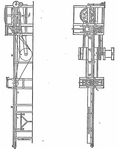
3 [J. McGregor, Jr. Planning Machine. Patened Aug. 28, 1833
994 is an infringement of the Wood-worth patent.
This same point has been contested and decided in cases arising in other circuits. In the case of Woodworth v. Wilson, 4 How. [43 U. S.] 712, earned by appeal to the supreme court from the circuit court for the district of Kentucky, an attachment was applied for in the circuit court, on the ground that a party who had been enjoined from using the Woodworth machine was using the Bicknell machine, and thus violating the injunction. The court in Kentucky, on the evidence produced on the application for an attachment, dissolved the injunction. We have examined the evidence in that case, from which it appears that the Bicknell machine, especially in its planing wheel, was similar to the Macgregor machine, in the points in which it is claimed that the latter is distinguished from the Woodworth machine. The case as presented to the supreme court did not turn upon the question whether the Bicknell machine was an infringement of Woodworth's patent; but that point was so involved in the case that it is not to be supposed that the court would have reversed the decree of the court below, without expressing an opinion that the Bicknell machine might be used without violating the injunction in favor of Woodworth's, if they had so thought. The testimony taken in the court
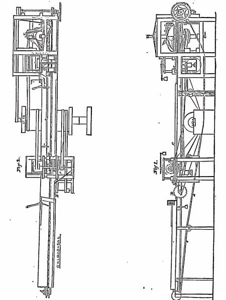
4 [J. McGregor, Jr. Planning Machine. Patened Jan. 9, 1838
 995 below, which was much at large, and was by both parties directed to the infringement by the Bicknell machine, was brought before the supreme court. That court reversed the decree below, and reinstated the injunction; the effect of which must have been to entitle the plaintiff in the circuit court to pursue his attachment there against the Bicknell machine. In the absence of a reasoned opinion upon the subject, we accept the decision of the supreme court as importing its judgment that the Bicknell machine was an infringement of Woodworth's patent. A ease has also arisen recently before the district judge for the Eastern district of Pennsylvania, on a motion for an injunction, which was granted, against what was there called a Gay machine, which, however, from the description given of it, was, in its construction, like the Macgregor machine. An injunction has also been granted by Chief Justice Taney in Baltimore against a machine which is said to have been a Macgregor machine.
Many affidavits have been presented on the part of the defendants to show that the Woodworth machine and that used by the defendants are wholly unlike; but these affidavits are, for the most part, wanting in any statement of the particulars in which the machines differ, or of the reasons on which the opinions given are founded. We have examined and compared the descriptions and models of the machines, and heard the arguments of counsel, and are thus enabled to form an opinion ourselves, and we think that the two machines combine substantially the same improvements.
It is contended on the part of the defendants that an injunction ought not to be granted, on the ground that the plaintiff has acquiesced in the use of this machine by the defendants; that he has known of its use and has not interfered to prevent it. We do not think this objection can prevail. It does not satisfactorily appear that the plaintiff knew how the defendants machine was constructed, or how far it infringed upon his; and, if he did know, we do not hold that he forfeited his right to protection by injunction against the infringement, because he did not apply sooner. He brought other suits, one against one of these defendants, to vindicate his rights; and he is not to be charged with acquiescence because he proceeded first against that which was a more palpable and obvious violation of his right, or because he has not brought suit against all the machines which infringe upon it. We order an injunction against the defendants pursuant to the prayer of the bill.
At a subsequent day, the defendants, having put in their answer, moved, before NELSON, Circuit Justice, and BETTS, District Judge, for a feigned issue to try the matter in controversy before a jury. The motion was argued by the same counsel as before. The opinions were given at the close of the argument.
NELSON, Circuit Justice. The defendants are struggling against the judgment of the court, already formed and expressed, on the motion, heretofore granted, for an injunction. Most of the questions in this case were then fully considered and decided. In Woodworth v. Wilson, 4 How. [45 U. S.] 712, which was taken to the supreme court from the district of Kentucky, the question of the originality of the invention was most thoroughly enquired into, as evidence from every quarter of the country was produced, by depositions of experts, and from books of science, and it was notwithstanding held that Woodworth was the first inventor, and that the specification of the patent of 1828, in connection with the drawing, was sufficient, and the patent valid. The questions, both as to the originality of the invention and as to the validity of the patent, were decided on the most full examination and argument. The case of Wilson v. Rousseau, 4 How. [45 U. S.] 646, from the Northern district of New-York, was founded on the amended specification of 1845. All the questions involving the validity of the new patent were raised in that case. It was argued at great length and the specification was held to be sufficient, and the re-issued patent valid. The new specification was but a clearing up of the criticisms which had been made on the old one in the course of the litigation had upon it. The supreme court having passed upon these questions and settled them, after argument, and on full consideration, how can we, on this motion, revise them? There is not a point made now which” has not been made before. The questions raised have, on several occasions, in the district of Vermont, and in the Northern district of New-York, been acted upon as settled, and we so regard them. The only question we can consider as open for controversy is that of infringement. To permit litigation to be renewed as to any other, would be to encourage a struggle against the deliberate judgment of the appellate tribunal. To that the parties must submit, until they can again bring the questions into that court. They can, of course, go into proofs in this case and the court will then pass upon them.
Then, as to the question of infringement. If on the hearing on pleadings and proofs we shall entertain doubts as to the identity of the two machines, we will direct the question to be tried by a jury. But it will be as to that point alone, the question of infringement If we do not entertain doubts on that question, it will be our duty to decide it; for we are not aware of any principle that will justify us in sending the case to a jury, unless we shall be brought to doubt on the question of identity.
In reply to an observation from the defendants' counsel, NELSON, Circuit Justice, 996said: The remittitur in Wilson v. Rousseau, 4 How. [45 U. S.] 687, was drawn up by me. The only reason why the answer to the eighth question certified (see pages 670, 688), was drawn in the manner it was, was that the question did not present a principle of law but a matter of fact But the court had no doubt as to the fact and virtually decided the question. Both patents, that of 1828 and that of 1845, were before us, and we had no doubt they were for the same invention.
BETTS, District Judge. It is not a matter of course to order a feigned issue; but the party applying must lay a foundation for it. This is not the case of a new patent, but of an old one, long in use and established by decisions. And this court must adhere to what has been passed upon by the court above, whether it is contained in the remittitur or not. A feigned issue is not to be granted, unless the opinion of the jury on a question is found to be needed. And after a jury shall have passed upon the question, it will be for the court to say whether the verdict is right; and the court may set it aside. In the position of this case at present, a feigned issue cannot be ordered. Motion denied.
[For a subsequent proceeding, see Case No. 16,852.]
[For other cases involving this patent, see note to Gibson v. Van Dressar, Case No. 5,402.]
NOTE A.5
McGregor Planing Machine. Patented August 28, 1833.
Improvement in machine for jointing, tonguing, grooving, and planing plank for flooring and siding for ceiling.
This machine contains jointing saws, also saws for cutting the tongue upon an edge of the boards fed to the machine.
The plank to be planed is carried forward between the saws by a chain.
There are gauges in the machine to guide the plank straight. The gauge which is behind the saw is made sharp at the forward end, and shaves off the edging that is above the tongue.
The gauges on the other side are adjustable so as to suit any width of plank. In front of the jointing-saw is a weight to keep the plank up to the stationary gauge.
5. The jointing is done by two circular saws: the one on the side farthest from the plane shaft is so placed as to cut the edge off in a line with the gauge that lies immediately after it; the one on the other side is placed in a movable carriage, operated by a graduating screw, so that it can be set to any width desired.
6. The tongue of the board is formed by four circular saws, the two placed on the perpendicular shaft have a chuck between them as thick as the intended tongue. This shaft is so placed that the two saws cut horizontally into the edge of the plank as far as the width of the intended tongue. Above and below the plank is a shaft placed horizontally with one saw on each—the one above cuts down to the cut made by the upper horizontal saw, the one below cuts up to the lower cut made by the lower horizontal shaft. These two last-mentioned shafts are so placed that the saws cut into the face of the plank as far from the outer edge as the tongue is designed to project
7. The groove is formed by three circular saws placed on perpendicular shafts, twining horizontally in the same carriage or frame, which carriage or frame is so constructed that it may be moved back or forward by a regulating screw to suit any width of plank to be dressed. On one of these shafts are put two circular saws, having a chuck between them of such thickness that the saws from outside to outside will be as far apart as the width of the intended groove; the other shaft carries one saw made thicker than the two just mentioned, and so placed that it clears out the timber between the cuts made by the before-mentioned saws.
8. The revolving circular plane is made in the following manner: The shaft is of cast-iron, with a cast-steel step fitted in its lower end, and a cast-steel bearing, about six inches in length, fitted in its upper end to admit the shaft to rise and fall without disturbing the upper box. Eight cast-iron arms project from this shaft; at the extremities of these is a circular cast-iron rim, projecting three-quarters of an inch below the arms; even with the under surface of which rim is a flange, projecting horizontally one and a half inch; the under side of which flange and rim is twined true, forming a smooth surface to pass freely over the plank to be planed. In this flange are sixteen slots, forming throats to admit the inner edges of the plane-irons, at the back part of which slots are projections extending from the top of the rim as far as the outer edge of the flange to which they are cast solid, having the same inclination as the irons. These projections form the back part of the slots as well as the bed-picces on which the plane-irons rest, and are fastened by screws, bolts, and nuts. Each plane-iron is four inches long and two inches wide; rounded on the outer corner, the front edge passing through the throat being nearly square; this edge, the outer corner and up the outer edge as far as the plank should ever, exceed the desired thickness, is made sharp. The foot-shaft of this rotary plane rests in a step, the latter being so made that the rotary plane can be adjusted vertically.
9. The feeding is performed by an endless chain passing over two wheels—one at the end of the frame in which the revolving plane is placed, and the other at the first end of the way. The first-mentioned wheel has cogs on its periphery, working in the links of the chain. On this chain are fastened hooks, which lay hold of the end of the plank on the chain, carrying it forward to the saws and plane.
10. Rollers for holding down the planks.—There are three of these rollers: one placed in front of the jointing and tonguing saws; one between these and the plane; and the other behind the plane—all held down upon the planks by weights and levers to confine the planks on the way.
11. Operation.—The machine being put in motion by steam or water-power, the plank to-be dressed is placed on the way in front of the jointing-saws, and carried forward by the motion of the endless chain to these saws, which joint its edge; it is then carried forward to the tonguing and grooving saws, passing under the rollers between the gauges, when it is tongued and grooved in the manner hereinbefore described; the endless chain then carries it forward to the circular revolving-plane, when it is planed smooth by the operation of the plane in the manner also hereinbefore described. The plank is then conducted out of the machine by the continued motion of the endless chain. The jointing may be performed in a separate machine; also the tonguing and grooving. And the planing likewise may be done in a machine distinct from the others, but all operated on the same principle as herein described. Rollers 997may also be fixed before and after the jointing-saws, to keep the plank firmly down upon the way.
Claim.—1. The planing of timber of any size or dimension by the principle of the twining tool and plane-iron united, as before described, or by the twining tool separate from the plane-iron, or so near as to retain the same principle. 2. The application of the sliding-box for the steps of the revolving plane-shaft to turn in, and by which the revolving plane is raised and lowered, to give the desired thickness to the plank, made and applied as before described. 3. The passing the shaft through beyond the face of the revolving circular plane, so as to have a step for the plane to rest on. 4. The application of the gauge under the plane to keep the stuff down while the plane is operating. This may be done by a roller, but I prefer the gauge. 5. The application of the common circular saw to joint, tongue, and groove plank or siding in the manner before described. 6. The mode of forming a tongue on a board, plank or sliding by cutting in the edge of the plank horizontally on each side of the tongue, and then vertically to form the shoulders by circular saws, as hereinbefore described. 7. The mode of forming the groove by making two horizontal cuts in the edge of the plank with two circular saws as far apart and deep as the width and depth of the intended groove, and clearing out the timber between the cuts by a circular saw, revolving horizontally in the manner herein described.
NOTE B.6
McGregor Planing Machine. Patented January 9, 1838.
Improvements in the machine for planing, jointing, tonguing, and grooving of boards, for which letters patent of the United States were granted unto me under date of the 28th day of August, 1833. The machine does not vary in its general construction and mode of operation from that above alluded to—that patented August 28, 1833; and it will not, therefore, be necessary to describe it minutely in the present specification, but only to particularize those things which constitute the improvements thereon.
Fig. 1, in the accompanying drawing (28 Fed. Cas. 994), gives a front, and Fig. 2 a top view of the improved machine. In my original machine the board or plank was jointed on both edges by two circular saws, set upon shafts nearly opposite to each other, this jointing having been the first operation performed by the machine, as the board entered it to be jointed, tongued, and grooved.
In the present improved machine, after placing the plank upon the bed of the machine, and conveying it forward by means of the endless chain A A, as formerly, it first comes in contact with the jointing-saw B, which joints one edge of it by rubbing a strip therefrom, which strip is carried off as heretofore. As it advances, the plank next comes into contact with the tonguing saws C C, which operate upon the jointed edge; whilst the second jointing-saw D, which stands opposite to the tonguing saws C C, joints the opposite edges. This arrangement removes a difficulty experienced in the old machine, in which the plank was jointed at the same time on both edges by two saws, as before noticed, and was subsequently made to encounter the tonguing and grooving-saws acting opposite to each other. It, however, was found impossible to prevent those slight deviations in the apparatus, which would affect the regularity of the tongue and groove, and consequently the matching of the plank. The first improvement which I claim consists in the foregoing new arrangement of the jointing and tonguing saws, namely, in the first jointing of one edge by a circular saw upon the first saw-shaft, and the subsequent jointing whilst the tonguing of the opposite edge first jointed is at the same time effected at a point opposite, or nearly opposite, to the second jointing-saw, as herein described. The plank, as it proceeds forward, is borne up against the gauge-strip E, on the front of the bed, by the movable gauges E E, as formerly; but to carry off the strip cut by the second jointing-saw, is added the guide-strip or gauge G, which is armed with a thin elastic plate of iron at that end of it which is toward the kerf of the saw, into which kerf it enters, and effectually removes the strip out of the way, and prevents its interfering with the grooving-saws H, as it sometimes did under the old arrangement.
The end of the elastic strip of iron is confined onto the frame of this second jointing-saw, so that when the saw is shifted the strip moves with it, and is thus always opposite to the kerf. The second claim to improvement is to the employment of the gauge-strip E in the manner and for the purpose set forth. The grooving-saws I are constructed and operate as in the original machine, and are in like manner supported upon a sliding frame J J, by which they may be adjusted precisely to the width of the staff to be grooved. The stuff, after being tongued and grooved, passes on between the stationary gauge-strip B and the opposite cheek or strip K K, which mates part of the sliding-frame L L. The strip E having a groove on it which receives the tongue of the plank, and the strip K a tongue which, in like manner, enters the groove of the plank as in the original machine, the plank is thus firmly held between these tongued and grooved strips, whilst it is acted upon by the revolving planes. As the sliding-frame which carries the grooving-saws I, and that carrying the tongued-strip K, require to be brought up simultaneously and equally against the plank which is to be grooved and planed, I have devised a new and improved mode of effecting this object. M M is a shaft which passes under the sliding-frames J J and L L, and has on it four pinions equal in size, which take into four racks—one on the under side of each of the side pieces of the two sliding-frames, and by turning this shaft by means of the wrench o or otherwise, it is manifest that the two sliding-frames will be simultaneously adjusted, as may be desired. This mode of adjustment, as arranged and applied to the planing machine, constitutes the third claim to improvement. In my machine, as originally patented, the cutters by which the planing was effected, consisted of a number of irons—usually sixteen—affixed in slots on the periphery of the revolving horizontal planing wheel, the edges of these cutters being carried so as to operate like gouges in turning, as described in the specification thereof.
The improvement in this part consists in the employment of a smaller number of irons—usually three—of greater width, so as to extend from the periphery of the wheel, or from the ends of arms which may be substituted for a wheel, to the shaft which carries it. The forward arm, or part of the wheel, forming the throat to the iron, not being extended as far out as the part forming the bed-piece to the iron, allows the outer end of the iron to spall off all that is above the desired thickness to be planed off. These wide irons, which are held and adjusted by suitable screws, are shown at N N N, attached to three arms, These irons are not placed in the direction of radii to the wheel, but stand in relation thereto in the manner of skew-irons in rabbet and other planes. These are not curved at their extremities, hut have straight-cutting edges; and their distinguishing characteristic is their being so set that they shall cut under the surface of the plank without coming into contact with the fibrous surface left by the saw and the gritty matter, always entangled therein. As 998the shaft of the planing wheel is not vertical, but has an inclination toward the plank, the edges of the irons or cutters will first enter that edge of the plank which is toward the shaft, cutting toward the center, and obviating all danger of spalling, and the iron will not begin cutting at the off edge until it is about returning toward the center, and, of course, it can not produce spalling there. I claim as my fourth improvement the particular mode above described, of constructing and arranging the plane-irons, or cutters, so that they shall cut under the surface of the stuff to be planed, they being in all respects made and arranged substantially in the manner set forth.
1 [Reported by Samuel Blatchford, Esq., and here reprinted by permission.]
2 NOTE [from Fish. Pat. Rep. 120]. “The plank or board is to be moved on toward the cutting edges of the cutters or knives, on the planing cylinder, so that its knives or cutters, as they revolve, may meet and cut the plank or board in a direction contrary to that in which it is made to advance; the edges of the cutters are, in this method, prevented from coming first into contact with its surface, and are made to cut upward from the reduced part of the plank toward said surface, by which means their edges are protected from injury by gritty matter, and the board or plank is more evenly and better planed than when moved in the reversed direction. * * *
“B B are the heads of the planing cylinder, and C C the knives or cutters, which extend from one to the other of said heads, to the peripheries of which they may be attached by means of screws. The knives C C, with the faces, forming a planing angle, may be placed in a line with the axis, J, of the cylinder, or they may stand obliquely thereto, as may be preferred.” [For drawings of the Woodworth patent above referred to and explanations thereof, see 10 Fed. Cas. 330.]
3 [From Fish. Pat. Rep. 120, from which was also taken the detailed description of this machine, published as note A, at the end of this case.]
4 [From Fish. Pat. Rep. 120, from which was also taken the detailed description of this machine, published as note B, at the end of this case.]
5 [From Fish. Pat Rep. 120.]
6 [From Fish. Pat. Rep. 120.]
This volume of American Law was transcribed for use on the Internet
through a contribution from Google. 