Case No. 10,749.
18FED.CAS.—74
PARKER v. STILES.
[5 McLean, 44; 7 West. Law J. 168; 1 Fish. Pat Rep. 319.]1
Circuit Court, D. Ohio.
Nov. Term, 1849.
PATENTS—CONFORMING TO REQUISITES OF THE LAW—CONSTRUCTION—MONOPOLY—CERTAINTY OF DESCRIPTION—CLAIMS NOT ORIGINAL—PRESUMPTION AS TO NOVELTY AND UTILITY.
1. In a patent suit the court must decide, by a fair construction of the patent, whether in all substantial particulars, it conforms to the requisites of the law.
2. Letters patent for invention are to be construed liberally.
[Cited in Ingels v. Mast Case No. 7,033.]
[Cited in Burke v. Partridge, 58 N. H. 351.]
3. The exclusive rights secured by letters patent are not to be viewed as odious monopolies, but as the result of a beneficent and wise policy.
4. If his invention is not described in his patent and specification with reasonable certainty and precision, the patentee can claim nothing under his patent.
5. The objects of the law, in requiring a full, clear, and exact description of the invention, stated.
6. If a patentee has claimed anything, as a material part of his combination, as new and 1164original with him, which is proved to have been discovered prior to the emanation of his patent, it is fatal to it.
[Cited in Tillotson v. Ramsay, 51 Vt. 313.]
7. In an action of the case, for infringement of a patent, where the patentee in good faith claims, in said patent, what is not original, and, on being apprised of the fact, does not within a reasonable time enter a disclaimer, he cannot recover, even if the jury are satisfied the defendant has infringed the parts of said patentee's invention that are original.
8. In the construction of a patent, the whole instrument, embracing the specification and drawings, is to be taken together; and, if, from this, the exact nature and extent of the claim, made by the inventor, can be perceived, the court is bound to adopt that interpretation and give it full effect.
[Cited in Ingels v. Mast, Case No. 7,033.]
9. The description of the invention in the letters patent, for improvement in the application of hydraulic power, granted to Zebulon and Austin Parker, October 19, 1829, considered, and declared minute and practical.
10. The first claim in said patent, when construed in connection with the prefatory part of the specification, is for a wheel called the compound vertical percussion and reaction wheel; the concentric cylinders inclosing the shaft, and the manner of supporting them; and the spouts which conduct the water to the wheel. The claim cannot be held to embrace the arrangement, or duplication of wheels on a horizontal shaft, as a part of the invention of the patentees. This arrangement is introduced, and perhaps unnecessarily, as described, as descriptive of the mode by which the wheels were to be used, but not as a part of the invention.
11. Reasons for such a construction of the patent considered.
12. A certain mechanical arrangement having been long known and used, before the patentee made and patented his invention, it cannot be presumed, that the patentee was ignorant of the fact, and intended to claim such arrangement as new.
13. In an action on the case, for the infringement of letters patent, to entitle the plaintiff to recover, the jury must be satisfied that the invention, embraced in the patent, is new and useful.
14. The patent raises the presumption of the novelty and utility of the plaintiff's invention, as the oath of the patentee to the originality and novelty of his invention, forming a part of the letters patent, and being in evidence to the jury, forms a legal groundwork for such presumption.
[Cited in Crompton v. Belknap Mills, Case No. 3,406.]
15. It is the province of the court to determine what constitutes novelty, and of the jury to determine, from the evidence adduced, whether the patentee's invention is new. The same rule applies to the subject of the utility of the invention.
16. Where a mechanical contrivance claimed to be essentially similar to that covered by the plaintiff's claim is set up in defense, and the proof relied on is a description of such structure contained in a printed publication, such description must be sufficiently full and precise to have enabled a mechanic to construct it; and must also be in all material respects like that covered by or described in the plaintiff's patent.
17. Proof of the previous use of a structure, bearing some resemblance to the improvement of the plaintiff, and which might have been suggestive of ideas, or have led to experiments, resulting in the discovery and completion of his improvement, will not invalidate his claim under his patent.
[Cited in Whittlesey v. Ames, 13 Fed. 898.]
18. To sustain the validity of a patent for an Invention, the latter must be, to some extent, useful. But courts are not rigid and strict, on this point. In the absence of proof, by the defendant, that the thing patented is absolutely frivolous and worthless, the presumption of utility, by the patent itself, would be sufficient, so far as this point is concerned, to sustain the patent.
19. On the question of infringement, the burden of proof is with the plaintiff.
20. To make out infringement, the plaintiff must prove that the defendant has used his invention, either in the precise form in which it is constructed under the patent, or in a form and on principles substantially the same.
21. To constitute this identity, the defendant's structure or machine need not be the same in appearance, form, or proportions as that invented and patented by the plaintiff. If the operative principle of the two machines be the same, the substantial identity, contemplated by the patent law, is established.
22. The principle of a machine is the particular means of producing a given result by a mechanical contrivance.
23. The use of mechanical equivalents and the identity of mechanical structures considered, in reference to infringement.
24. The question of the identity of the invention embraced in the plaintiff's patent, and of that used by the defendant, is to be decided by the jury upon the evidence.
25. Great respect is due to the views and opinions of scientific individuals, and practical mechanics, on the question of the identity of different mechanical structures.
This is an action on the case [by Zebulon Parker against John Stiles] for an alleged infringement of a patent for an improvement in the application of hydraulic power, granted to Zebulon and Austin Parker, dated 19th of October, 1829, and renewed for an additional seven years from the expiration of the term of the original patent, thereby extending its duration till October 19th, 1850.
2[The specification of this patent was as follows:
[“To all to whom these presents shall come: Be it known, that one Zebulon Parker and Austin Parker, of the county of Coshocton, and state of Ohio, have invented a new and useful improvement in the application of hydraulic power, by methods of combining percussion with the reaction, applied and exemplified in: 1. A compound vertical percussion and reaction water-wheel, for saw-mills and other purposes, with the method of applying the water on the same. 2. An improved horizontal reaction water-wheel, with the method of combining percussion with reaction on it. 3. A method of combining percussion with reaction, on common reaction wheels, or those already in use; and that the following is a full and exact description of the construction and operation of the several parts of said improvement, as invented by us. The principle upon which this improvement 1165is founded, is that of producing a vortex within reaction wheels, while, by its certrifugal force, it powerfully accelerates the velocity of the wheel, and adds proportionately to its momentum.
[“I. The compound vertical percussion and reaction wheel has two, four, six, or more reaction wheels, on a horizontal shaft made of iron or wood (iron generally being best), which shaft has the crank, to which the pitman and saw are attached, at one end of it. The number of wheels necessary, their diameter, and the quantity of water they will require, depend on the height of the head of water and the power and velocity required in general. If the head of water be under six feet, six wheels will be necessary; between six feet and ten, four will be required, and above ten feet, two wheels will be sufficient. For doing work with one saw, if six wheels were required, a single one is placed on each end of the shaft, and two double ones between them, equally distant from the single ones and from each other. If four wheels are necessary, a single one is placed on each end of the shaft, and a double one in the middle, and if two wheels only are used, a single one is placed near each end of the shaft. The diameter of a wheel for a head of six feet, and under, should be about twenty-eight or thirty inches, and the diameter must be increased, and the rims of the issuing section of the wheel diminished, in proportion to the increase of the velocity of the water, as the head increases in height. The following is a description of a wheel, and its appendages, for a head of seven feet, which may serve generally as data to base the other calculations of other heads upon: The horizontal shaft is about eight and a half feet long, exclusive of the gudgeons, and if made of wood, about nine inches in diameter; if of iron, about five inches. Between the wheels, the shaft should be turned round and true. Four wheels being necessary, a single one is placed on each end of the shaft, and a double one in the middle. The wheels are thirty-four to thirty-six inches in diameter. For the single wheels, solid heads four or five inches in thickness are firmly fixed on the end of the shaft. They are reduced on the inside (or sides next each other) to the thickness of two and a half inches at the edge, and they must be of the same thickness, four inches, in toward the shaft. In each of these solid heads, on the inner sides, five buckets (so called), made of sheet-iron, cast-iron, or wood, are fixed. They are five inches wide, and two and a half inches longer than one-fifth of the circumference of the wheel. The edges of these buckets are set half an inch into the heads. About three-eighths of an inch from the verge of the heads, a circle is made, upon which the inside of the points of the buckets is placed. Another circle is drawn two and a half inches within this, upon which the outer side of the head or inner ends of the buckets are placed. The inside of the points of the buckets follow the circle upon which they are placed about two and a half inches. On these buckets so placed, and set into the heads, wooden rims, equal in diameter with the wheels, two inches thick, and about three and a half inches wide, are put, the edges of the buckets being set one-half an inch into them. The wheels thus formed, are firmly bound together by screw-bolts, passing through the buckets. The middle wheels-are made in the same manner, except that one solid head answers for both wheels, and-it is reduced on both sides from five or six inches at the shaft, to two and a half inches at the edge. Light iron bands should be put on the heads and rims of these wheels. The distance between the rims of the different wheels should be twenty-nine to thirty-two-inches. These four wheels (so formed) will have an issuing section of two hundred-square inches, each wheel having fifty inches, and each issue ten inches. The direction of the issues are at right angles to radii of the wheels drawn through them; a tangent to the circle on which the heads of the buckets are placed. The middle of the buckets, or that part of them between the two circles, should form a regular and natural curve. The best buckets are made of sheet-iron. They should be doubled from the heads, the two ends of the piece forming the point of the bucket. They are left open enough in the middle for the bolts to pass through them. If they are made of cast-iron, they have holes or grooves for the bolts. If of wood, the ends or growth of the wood should be inserted into the heads and rims, and the bolts pass through them, or, the bolts being square, may form part of the bucket. Wooden buckets are practicable in large wheels, but inferior to iron. The penstock, or bulkhead, for this wheel, is in width equal to the length of the shaft, and has a perpendicular breast. The breast is formed of three posts, set in the cross-sill, the top of which sill is level with the bottom of the penstock. The middle one of these posts is from eighteen and a half to twenty-one inches wide, and about ten inches thick, and the two end posts are each from sixteen and a half to eighteen inches wide, and as thick as the middle post. The two spaces between posts are each twenty-four inches. The breast continues perpendicularly below the top of the cross sill about forty-four inches. The plank of this part of the breast is put on the front of the sill perpendicularly, above the sill. The posts are planked in their rear horizontally. Each of the posts may be double, or made of two pieces, and have spaces between them. The wheel is hung in front of the lower part of the breast, about a foot from it, with its top about level with the penstock. It is hung in upright hanging posts or beams, which may be elevated or depressed by wedges at the top of the penstock, the tops of the posts being put through timbers, and they may bewedged 1166horizontally at the bottom. The wheel should be immersed to its center (or lower) into the water below the mill at its common low stage. The middle of the spaces between the wheels must correspond with, and be directly in front of the middle of the spaces between the posts. About a foot in front of the wheel, four studs or posts, which are four inches thick and eight or ten inches wide, are set with their edges to the wheel. The spaces between two of these posts on either side must be about twenty-two inches. The middle of the spaces must correspond with the middle of the spaces between the wheels. The tops of these posts or studs are about level with the top of the wheel, or a few inches higher. They are inserted into a sill, or floor, at their bottoms, and are held firmly to their places by a plant or piece of timber fixed on their tops. Two cylinders, concentric with the shaft, and with each other, are placed in each space between the wheels. Their height is twenty-seven inches, leaving a space of from half an inch to an inch and three-quarters between. The ends of the outer cylinders are about half an inch less than the inner diameter of the outer cylinders and the rims of the wheels. The inner diameter of the outer cylinders is about half an inch less than the inner diameter of the rims of the wheels. The inner diameter of the inner cylinders is about ten inches, and its thickness about an inch. The spaces between the concentric cylinders are consequently about eight inches. The larger cylinders are held stationary by a sort of wooden frames, or rims, which support them. The frames are each made of two pieces of plank eighteen inches wide and one inch and a half thick, and of sufficient length to reach from the lower part of the breast to the studs in front of the wheel. They have their edges joined together by broad dowels and draw-pins, near their ends. Circular holes are made in the middle of these joined planks or frames, large enough to receive the ends of the larger cylinders, into which these ends are put and made fast. The ends of these frames are reduced in width to about twenty-six inches, by taking off the bottoms of the lower planks at their ends. The frames are supported by having their ends inserted into grooves or mortices in the lower part of the breast, at one of their ends, and into grooves or mortices in the studs, in front of the wheel, at their other ends. The joints of these frames lie level, and they, together with the cylinders, must be made to part horizontally into two equal segments, for the purpose of getting them to their places round the shaft. To prevent the water from escaping between the ends of the larger cylinders and the rims of the wheels, additional sections are made to the internal surfaces of the larger cylinders, which extend into the wheels. These additions of the cylinders are made of rolled or hoop iron. They are held to their places by means of boards an inch thick, eighteen inches wide, and thirty-six inches long, which have semicircles cut out of the middle of their sides, nearly equal in diameter to the internal diameter of the rims of the wheels. A half of each of these hoop, or additional sections, is nailed into each of the semicircles in the boards. Two of these, boards joined together in such a manner that the hoop appears complete, are screwed against the frames that support the cylinders, and fit closely against them, and the ends of the cylinders. One edge of each hoop will consequently fit closely against each end of the larger cylinders, and the other edge should extend about an inch into the wheels. The outside of the hoops should be as close to the inside of the rims of the wheels, as they can be, without touching them. The holes in the boards which support the hoops, through which the bolts go that fasten the boards to the framing, should be considerably larger than the bolts, and the heads of the bolts should be broad, in order that the hoops may be kept to their proper places. These additions to the cylinders, extending into the wheels, may be made of cast-iron, and be supported by iron plates, screwed against the frames in the same manner as the boards, or the continuation of the cylinders may be wood, instead of iron. Iron hoops may be supported by the cylinders themselves, instead of boards or plates; but in this case, it is difficult to keep them to their proper places. From the breast, immediately above the bottom of the penstock, two spouts are inserted, through the outer cylinders, into the spaces between the cylinders. The spouts are as wide as they can be made between the posts of the breast. The top surfaces of the bottom plank of the spouts are tangent to the outer surfaces of the inner cylinders, and the bottom surfaces of the top planks of the spouts are consequently about eight inches deep, where they join the cylinders, and they should be about fifteen inches deep, where they are inserted into the breast. A partition, an inch thick, is put into each spout, dividing it perpendicularly into two equal parts. This partition, as it winds round between the cylinders, increases in its thickness, and its surfaces on both sides become regularly nearer to the wheels, till in going once round they terminate on the sides of the ends of the spouts next the wheels. These doubly spiral partitions support the inner cylinders. The water passes over the shaft, and the top of the wheel runs from the breast. At the bottom of the penstock, and joining the breast a common chamber is made, out of which the wheels are supplied through the spouts. The chamber extends across the penstock, and is about four feet wide, and twenty inches high. In the top of this chamber, there is an aperture six feet long, and two feet four or five inches wide. Over tins aperture, a light hollow or box gate is placed, which is 1167six feet two inches long by two feet six or seven inches wide, and sufficiently high to extend to a proper distance above the surface of the water in the penstock. It is made to fit neatly on the floor or top of the chamber, and, when it is down or shut entirely, covers the aperture into the chambers. It is hoisted by the wooden swords, hinged At the inside of the gate, near the bottom, the swords also being hinged at the top to two arms extending from a roller, which is placed near the top of the gate. The roller is turned by levers, in any way that is convenient. The gate should hoist at least a foot. It is scarcely necessary to observe that care must be taken, by good racks and otherwise, to prevent the wheels from being choked in their issue.
[“II. The improved horizontal reaction water-wheel, with the method of combining percussion with its reaction. The dimensions and proportions of the wheel and its appendages, also, must vary to suit the head of the water, the power required, and other circumstances. The following are nearly the proper dimensions of the wheel and its appendages, for grinding with a stone four feet in diameter, with a head of water six feet high: The wheel is four feet and a half in diameter; it has five issues three and a half inches by five inches deep; the buckets are made of wood; they are an inch thick at the head, or ends, next the shaft, and increase to about an inch and a half thick in the middle, and from the middle decrease to about three-fourths of an inch at the points or outer ends. The issues are made to direct the water at right angles to radii drawn through them. The inside of the points of the buckets follow the circle on which they are set four or five inches, and the outside of the heads follow their circle about two inches. The points of the buckets extend by the heads about two and a half inches thick and about five inches wide, or no wider than sufficient to cover the buckets. The edges of the buckets are let into the head and rim about three-eighths of an inch. The wheel is bound together by screw bolts, which pass through the thick parts of the buckets. The rim is made true in the inside by turning, after the wheel is hung. The grain of the wood of the bucket stands upright. The wheel is placed or hung with its center four or five feet in front of the breast of the bulk-head or penstock, and about half immersed in water below the mill at its common low stage. A sill is placed on each side of the wheel, eight or ten inches from it. The tops of these sills are about an inch higher than the tops of the wheels. The sills support a frame or platform, five feet square, made of plank fifteen inches wide three inches thick, the principal bars of which are long enough to reach across the space between the sills. The inside of this platform is made circular, to the same diameter as the inner diameter of the wheel. In this circle, the cylinder that directs the water into the wheel, is erected. The inner surface of the cylinder extends below the platform into the wheel. The cylinder above the platform is fourteen inches high on that side of the wheel which runs from the breast, and it is reduced to the platform by a spiral line running from the breast, and downward, till it terminates on the platform directly under where it started. The part of the cylinder above the platform should be about two inches thick, and that part which extends into the wheel below the platform should be about half an inch thick. An inner concentric cylinder, the outer diameter of which is eighteen inches, its thickness one and a half inches, and its height four or five feet, is placed round the shaft, with its lower end even with the top of the wheel. In the outside of this inner cylinder a spiral groove is made, which corresponds with the spiral top of the outer cylinder. A screw-like covering is made over the space between the cylinders, having one of its edges inserted into the groove in the inner cylinder and the other nailed on the top of the outer cylinder. This covering supports the inner cylinder, between the beginning and termination of the covering and the inner and outer cylinder or section admitting a passage into the wheel, thirteen inches wide and fourteen inches high. To this section a spout from the penstock or bulkhead is joined, whose internal sections at the junctions exactly correspond with the section forming the passage into the wheel. The largest end of the spout or the end joined to the penstock is fourteen inches deep by about twenty inches wide. The spout has an inclination from the penstock equal to the inclination of the top of the outer cylinder. A common sliding gate shuts over the ends of the spout in the penstock, or it may have a chamber and a hollow gate similar to that of the saw-mill.
[“III. The method of combining percussion with reaction on common reaction wheels, or those already in use. The common reaction wheel runs under the floor of the penstock. Through the floor a circular hole is made, nearly equal in diameter to the internal diameter of the rim of the wheel, and it is made concentric with the wheel. This hole, through the floor of the penstock, is lined with staves, which extend from the floor into the wheel, and prevent the water from wasting between the floor and the wheel. The internal surface of this staving is called the cylinder. To apply the principle of percussion to one of these wheels, and combine it with its reaction, place on the level floor of the penstock a rim of wood whose inner diameter is equal to the diameter of the cylinder. This rim may be from eight inches to a foot wide, and four or five inches thick at the outer verge, and about one inch thick at the inner edge, the top being sloped downward toward the center of the wheel. On this rim are placed, at equal distances 1168from each other, with their edges up, from five to ten pieces of planks, or blocks, four or five inches thick, in the middle and about an inch thick at either end, the inner side or side next the shaft being plane, and the outer side circular, or nearly so. The inner or plane sides of the blocks are placed tangent to the cylinder. They are about twelve inches high above the rim at their inner edges, and about fifteen inches high at their outer ends. On these blocks an inverted conical covering is put, which is made to fit the tops of the blocks, the apex of which should come near to the bottom of the wheel. In the center of this covering a circular or square hole is made, into which a cylinder or square box is fixed, which is sufficiently large to inclose the shaft and leave it room to run freely, and long enough to reach to a proper height above the water in the penstock. The water is let into the penstock, when the wheel is required to run, by any sort of gate usually employed in such circumstances, or it may be let in through a chamber by a hollow gate. Another mode of applying the principle is to set the blocks that guide the water into the wheel tangent to a circle two inches outside of cylinder, and cover them with a rim that will only cover them. On the circular space between them, the ends of the blocks (or guides for the water) and the cylinder, a light hollow cylinder gate is placed, which incloses the shaft of the wheel. The outer diameter of this gate is three inches larger than the diameter of the cylinder, or inner surface of the staving. When this gate is to its place and shut, or down, it stands directly over and forms a continuation of the cylinder, extending to a proper height above the water in the penstock. It is hoisted by two swords of wood, or rods of iron hinged to the gate near the bottom, either within or without, the tops of the swords or rods being hinged to arms from a roller near the top of the gate, which is turned by a lever or levers. The gate is guided and kept to its place by four pieces of timber, or joists, across the penstock. One of these joists is placed on each side of the gate, about eighteen inches from the floor of the penstock, and one at each side, at the top, when the gate is down or shut. The edges of these joists are to the gate, nearly touching it. In the edge of each, at the point nearest the gate, a perpendicular notch or groove is made, an inch, or an inch and a half wide, and about the same depth, in which tongues or slides attached firmly to the sides of the gates slip up and down. The gate, however, may be guided and hoisted in any other way, if circumstances require it. The dimensions here laid down, the number of apertures into the wheel, and their size, must vary accordingly to the height of the head of water, the power required, and other circumstances. As a general rule for all wheels, however, the sum of the sections into the wheels should not vary far from being double the sum of the sections of the reacting issues of the wheels. The principle of combining percussion with reaction is applicable to inverted wheels, either by single spouts with spiral terminations between cylinders, having their inclinations upward into the wheels, or by inverting the rim with its blocks and conical covering, so as to send the water upward into the wheel.
[Drawings of patent No. 2,726, granted July 16, 1842, to Eli B. Lansing, published from the records of the United States patent office. For drawings of the Parker water wheel, see Case No. 10,736.]
[“The parts of the above-described machinery claimed as original, and our Inventions, in all their necessary dimensions and proportions, and for the use of which we ask an exclusive privilege, are as follows, viz: 1. The compound vertical percussion and reaction wheel for saw-mills and other purposes, 1169with the four, six, or more wheels on one horizontal shaft. The concentric cylinder, Involving the shaft, with the manner of supporting them. The spouts which conduct the water into the wheels from the penstock, with their spiral terminations between the cylinders. 2. The improvement in the reaction wheel, by making the buckets as thin at both ends as they can safely be made, and the rim no wider than sufficient to cover them. The inner concentric cylinder. The spout that directs the water into the wheel, and the spiral termination of the spout between the cylinders. 3. The rim and blocks or planks that form the apertures into the wheel, and the manner of forming the apertures. The conical covering on the blocks, with cylinder or box in which the shaft runs, and the hollow or box gate in any form, either cylindrical, square, rectangular, or irregular.
Zebulon Parker,
“Austin Parker.
[“Witness:
[“John Jacobson,
[“Laban Lamat.”]2
The particulars of the plaintiff's claim will be best understood from the instructions asked by his counsel, and substantially given by the court, which are as follows:
Instructions asked by plaintiff:
I. As to the validity of the patent: (1) It is the exclusive province of the court to construe the patent, and determine what the patentee claims to have invented; and of the jury to determine whether he has in fact made, and sufficiently described the invention so claimed. And the rule of construction is very liberal in his favor, especially as to patents granted prior to the present law passed in 1836. (2) So far as the present action is concerned, the patentee claims: 1st. The improved wheel by itself. He does not claim the invention of a reaction wheel, nor of the idea of pairing or duplicating wheels upon a horizontal shaft; but simply his improved wheel. 2d. He claims the improved method, described by him, of conducting and applying the water to the wheel. This consists of a spiral scroll block placed between two concentric cylinders. Of these, he claims this use of concentric cylinders as a distinct invention, but not the spiral scroll block. 3d. He claims a distinct invention, the combination of the spiral scroll block with the concentric cylinders, so as to produce the spout or sluice described by the patentee. (3) In order to sustain his claim, the plaintiff must satisfy the jury that his invention is sufficiently described. Of this they are the exclusive judges. And the test is, whether the description contained in the specification and drawings, is so full, clear, and exact, as to enable a skillful millwright to construct the machine without invention of his own. (4) The plaintiff must also satisfy the jury that he was the original and first inventor, and that his invention is useful. The test of originality is, that the thing invented was not before known to him. The test of novelty is, that the thing invented was not known to, or used by other persons in a public manner, and not described in any public work. The test of utility is, that the invention is of some utility, and not simply frivolous; but the degree of utility is not important. And of all these matters, the production of the patent is prima facie evidence, throwing upon the defendant the burthen of proving the contrary. (5) The claim in this case being for the invention of distinct parts of a machine, and not for a new combination of old elements, if the defendant relies upon a prior public knowledge or use, he must satisfy the jury that substantially the same parts or elements were publicly known or used in the same way before the alleged invention of the plaintiff. (6) If the defendant relies upon a prior description in some public work, he must produce a work containing such a description as would be sufficient in a patent.
II. As to infringement: 1. The term principle, as applied to machines, does not mean a philosophical principle, which is not the subject of a patent. But it means the particular method of producing a given result by mechanical contrivance; and where a similar result is produced in substantially the same way, there is an identity of principle, and consequently an infringement, although the mechanical contrivance may be different in form or proportions, or by the substitution of mechanical equivalents. (2) Where the invention of the plaintiff is of distinct parts of a machine, and not of a new combination of old parts, it is an infringement to use any one of those parts; and if the defendant uses either substantially the same wheel, or substantially the same mechanical contrivances for introducing or applying the water to the wheel, he is guilty of an infringement. (3) If the jury believe that the mechanical contrivances in the Lansing machine, as used by the defendant, for introducing and applying the water to the wheel, operate in substantially the same way to produce the result, as those invented by Parker, then there is an infringement of Parker's patent. And this consequence is not avoided by simply changing the form or proportions of the machine, or by substituting one or more mechanical equivalents. (4) Supposing the Parker patent valid, the only question for the jury is, whether the spiral scroll case placed between an outer cylinder and an enlarged shaft, which may be an equivalent for an inner cylinder, produces substantially the same effect, by substantially the same mechanical contrivances, as the spiral scroll block placed between the two concentric cylinders in the Parker machine. If so, the alterations are merely colorable evasions, and there is an infringement.
The nature of the defence will perhaps best 1170appear from the instructions asked by defendant's counsel, and which are as follows: (The jury, by consent, were permitted to take with them in their retirement both sets of instructions.) (1) That the claims enumerated under the first head of the summary of the plaintiff's specification are: 1. “The compound vertical percussion and reaction wheel, with two, four, sis, or more wheels on one horizontal shaft.” This is a claim to the entire wheel described. It is not stated that any particular part of this compound wheel is claimed, nor that the combination of the whole is new. In law, therefore, the claim is for the whole compounded wheel, and also, for each particular part of which it is composed, and if any particular part of this compound “turns out to be old, or the combination itself not new, the patent is void.” (2) The second and third items mentioned under this head of the summary, are the concentric cylinders enclosing the shaft, and the spout with its spiral termination between them. These things are specially claimed as parts. Being so claimed, if any of them are found not to be new at the time of the plaintiff's invention, or were described in the Dictionary of Arts and Sciences, which is in evidence, the patent is void. (It is claimed by the plaintiff's counsel that the second and third claims of this summary entitle them to claim them in combination, although they are not so claimed in the specification; if the court should be of that opinion, then,) we ask the court to charge the jury: (3) That they must be satisfied that the patentees were the inventors of the entire combination. If these parts were before used in any combination less than the whole, or if the combination up to a certain point had before existed or been described in a public work, and the patentees have only added other parts to the old Combination, the claim to the entire combination of these parts cannot be sustained. (4) That where the claim is for a combination of parts, the use of any of these parts less than the whole is no infringement (5) We ask the court further to instruct the jury, that a contrivance or part of machinery, to constitute a mechanical equivalent, must be used to produce the same effect, substantially in the same way. That the names or forms of things are of little importance. To be mechanical equivalents, they must accomplish the “same purpose, object, or effect.” If their forms are alike, but their effects are different, they are not equivalent.
(As there are many suits pending in the United States for the infringement of the Parker patent,—more than two hundred in Ohio alone,—we shall attempt to give a very condensed statement of the evidence.)
Evidence for the plaintiff:
Isaac Morton testified to the admission of defendant that he was using a turning wheel and that the model in court was a correct representation of it. Is well acquainted with the construction of water wheels. Considers that Parker's wheel is a great improvement over the old reaction wheels previously in use. That the arrangement of the concentric cylinders and the spiral terminating spout, are new and useful improvements. Had never seen these improvements before the date of Parker's patent. The object and effect of them are to apply the water to the wheel in the line of motion, and at as great a distance as possible from the centre—giving it greater leverage. Has used the old reaction wheel and Parker's improvement—find a gain of twenty per cent in the latter over the former. Can saw as much with a Parker's with six feet head, as with the old reaction wheel with nine feet head of water. The scroll keeps the water up to its work, by diminishing in volume as the water is expended. The application of the water to the wheel in the Lansing wheel, is substantially the same as Parker's. Lansing's will do more work with the scroll than without it. The scroll is an improvement to the action of both wheels.
James Sloan: “I have followed the millwright business twenty-seven years. Have made many experiments in the application of hydraulic power. I consider the improvements of Parker in the wheel, and in the method of applying the water, to be original with him, and of great service. There is a gain in Parker's of twenty per cent over the old reaction wheels. Lansing's scroll is the same in principle as Parker's—has the same effect. The water impinges upon all the buckets at the same time, by means of substantially the same contrivance. The enlarged shaft in Lansing's is a mechanical equivalent for the inner cylinder of Parker's.”
Dr. Thomas G. Clinton: “I have been a member of the examining corps in the patent office. The class of water wheels was within my supervision. I have examined Parker's patent in the office—applications were frequently rejected upon it. I saw Lansing's patent there. The points of novelty in Parker's wheel are the narrowed rim, and the method of forming the heels and points of the buckets of area of circles, making the issues tangential. The concentric cylinders and the wedge-shaped scroll are novelties. The water passing between the cylinders acquires a vertical motion, and the scroll diminishing in its violence by approaching the face of the wheel, keeps it up to its work. The water is applied in the most economical and efficient manner. Lansing's wheel is enclosed in a spiral scroll shute, which is made to traverse round and approach its outer verge. It is substantially the same as that of Parker's in intention and operation. The vertical motion would not be so perfect without the inner cylinder, nor could the water be so economically applied without the scroll. The part of the wheel 1171to which the helix is applied makes no substantial difference.”
Edward H. Knight: “I am a patent agent, and hare examined water wheels in the patent office and elsewhere. I have examined the Parker patent, and seen the wheel in operation. The water is let on from a sluice between concentric cylinders. The outer cylinder gives it a vertical motion, and the inner cylinder keeping it from the centre gives it greater effect. The scroll which winds round between the cylinders gradually approaches the face of the wheel, directs the water towards the wheel, and, diminishing in volume as it passes round, in proportion as the volume of water is diminished by passing through the issues, keeps the remainder up to its work, causing the water to press equally upon the whole circumference of buckets. In the wheel there are points of novelty in the rim, the buckets, and the issue, which have been before explained. The method of applying the water in Lansing's is substantially the same, the effect on the oblique buckets identical. The scroll shute which winds round the wheel has the effect of keeping the diminishing volume of water up to its work as the scroll in Parker's, and also of giving the vertical motion which is the duty of the outer cylinder in Parker's. The enlarged shaft in Lansing's performs the office of the inner cylinder of Parker's. The spiral is identical in its effect in both, and there are in Lansing's mechanical equivalents for the inner and outer cylinders of Parker's. Economy is secured by the use of the scroll.”
Jesse J. Cail testified to the fact that defendant had told him that the Lansing wheel would do double the work of the flutter wheel, under same head.
For the defendant:
Clark Williams: “I have been engaged in the practical application of hydraulic power. The principal power in Parker's wheel is reaction, caused by destroying the equilibrium of pressure in the wheel. The Toulouse wheel exhibited, involves the same principles of action as Parker's—that is, they are both reaction. The issues and discharge are different Parker's is superior in that respect. The introduction of the scroll block is an improvement, by preventing disturbing currents. It preserves the current in its proper place, does not accelerate it. There is little or no percussion in the wheel. There is a whirling motion produced in the Toulouse similar to that in the Parker wheel, the scroll having the same effect as Parker's outer cylinder. Lansing's scroll has the same effect as the cylinder in the Toulouse in producing a vertical motion, and as the scroll in Parker's in diminishing in volume and preventing disturbing currents. The scroll block is of no service with a vertical shaft. There is no vertical motion in the cylinder when the wheel is full. Lansing and Parker have spiral scrolls for bringing up the diminishing volume of water to different surfaces for the same purpose. The power of reaction is sufficient to account for the motion of Parker's wheel.”
Dr. Chartres: “I have had in former years some practical experience in millwrighting. In Parker's wheel and method of applying the water, the scroll is injurious, for it creates greater friction. There is no value in the inner cylinders—they have no effect in directing the water. The Parker wheel is the best wheel exhibited; in its mechanical construction it is much superior. The application of the scroll in Parker's and Lansing's only differs in the part of the wheel to which it is applied—to the periphery of one and the face of the other; it has the same good effect and the same evils in both. Parker's is the best Were the scroll removed from the Parker wheel, it would be similar to the Vermont wheel as exhibited by model. A square fore-bay is as good as a cylinder. The inner cylinder is new, but the wheel is the only valuable part of Parker's invention.”
(Several witnesses deposed to the existence of several pairs of wheels on a horizontal shaft, prior to the issuing of Parker's patent. And this was admitted by plaintiff's counsel, in relation to wheels constructed by Roswell Wilcox.)
Russel Bradley: “In 1825 or 26, I saw several cast iron reacting wheels placed on a horizontal shaft, in a mill at Willesden, Chittenden county, Vermont. I constructed the model exhibited in court. The gate was not hoisted, and I could not see the interior of the case between the wheels. I have shown several things in the model that I did not see, and suppose them to be correct. I guessed at a great part of it. It was a new wheel. I did not examine it closely. I have guessed the whole interior arrangement; I did not look in.”
John Pope testified to having seen two wheels on a horizontal shaft with a water split between them, in the year 1818, in Morgan county, Ohio. The case between the wheels was cylindrical, and the water was introduced under the shaft; the half of the cylinder over the shaft was solid, not admitting the water, which only filled the buckets as they came round to the lower half of the case.
Christopher Aumack testified to having seen in 1824 or 25, near Eldridge, Onondaga county, New York, a scroll round a wheel on a vertical shaft with radial floats, like an inverted flutter wheel—described it as similar to Lansing's.
(Several millwrights testified that they considered the scroll block injurious, and others that it had no effect, and might be reversed without alteration in the power of the wheel, and others as to the power attainable by the different methods of applying the water, overshot, undershot, reaction, &c, &c.)
1172Plaintiff rebutting:
Dr. T. G. Clinton, recalled: “I have examined the Toulouse, Vermont, New York, and Parker wheels. There is a slight resemblance, but a substantial difference. The tendency to a vertical motion in the Toulouse is very imperfect—there are eddies produced; the action is principally by percussion. There is no vertical motion in the Vermont wheel; the water is admitted under and over shaft.”
James Sloan: “I have experimented with and without scroll. I obtained a co-efficient of 64.3 per cent, without, and 71 with the scroll; the old reaction gave 50.3. On reversing the scroll I obtained 02. There is a substantial difference between the Vermont and Toulouse wheels, and Parker's. Neither of the former have an inner cylinder nor a scroll. I always, in putting in wheels, use the scroll. A wheel is loaded when more water is let on to a wheel than the issues require.”
Edward H. Knight: “I consider that there is a substantial difference in the application of the water, in the Vermont, Toulouse, and the Parker wheels. There can be no vertical motion in the Vermont wheel, due to the method of applying the water,—whatever motion may exist is produced by the wheel, and is a waste of power. In Parker's the vertical motion is produced for the purpose of more effectually applying the power of the water; while in the other the wheel is made to keep a body of water whirling round. Though water in a state of quiescence presses equally in all directions, water in motion presses with, greater power upon surfaces placed across its line of motion, than surfaces parallel to it. There is in the application of the water and in Parker's wheel, a power over and above what is due to reaction, derived from the impingement of the water with a momentum due to its velocity, upon the buckets placed obliquely in its line of motion. It may be called percussion. I see no reason to quarrel with the term.”
(Several millwrights were called, who testified that they used the scroll, and that when carefully put in, it very materially assisted in driving the wheel, and that by it great economy of water was attained.)
H. Stanbery, T. Walker, and H. C. Noble, for plaintiff.
G. B. Smythe, N. H. Swayne, and S. Galloway, for defendant.
LEAVITT, District Judge (charging jury). The plaintiff, under a patent issued originally to Zebulon Parker and Austin E. Parker, dated the 19th of October, 1829, and renewed in the name of Zebulon Parker, October 19, 1843, claims an exclusive right to an improvement in the application of hydraulic power to a water wheel, and seeks to recover in this action, for an alleged infringement of that right, by the defendant, in the use of a water wheel, known as the Lansing wheel. It is the duty of the court, by a fair construction of the patent, to decide, whether in all substantial particulars, it conforms to the requisites of the law. And it is now a principle, settled by the concurrent opinions of some of the most enlightened jurists of this country, that patents, securing to inventors the just rewards of their labor and industry, are to be construed liberally, and with a fair purpose of carrying out the object of the constitutional provision on this subject, and the legislation of congress based upon it. It is now justly held, that these exclusive rights are not to be viewed in the light of odious monopolies, but as the result of a policy, at once beneficent and wise. The constitution of the United States (article 1, § 8) has conferred on congress, among other delegations of power, the right to pass laws “to promote the progress of science and useful arts, by securing for limited times, to authors and inventors, the exclusive right to their respective writings and discoveries.” And congress, in the exercise of the power thus granted, have from time to time passed laws on this subject, designed to give practical effect to the constitutional provision. At this day, there are probably few who doubt the justness and wisdom of this policy. That it has been followed with good results, in stimulating our countrymen to intellectual effort, and has thereby contributed essentially to our rapid national advance in “science and the useful arts,” is too clear for controversy.
Without extending this view, I proceed at once to the inquiry, whether the plaintiff in his patent and specification, has so far complied with the provisions of the patent law, as to be entitled to the benefits of the invention which he claims. If this invention is not described with reasonable certainty and precision, the patentee can claim nothing under his patent. The statute requires, “that before any inventor shall receive a patent for any such new invention or discovery, he shall deliver a written description of his invention or discovery, in such full, clear, and exact terms, avoiding unnecessary prolixity, as to enable any person skilled in the art or science to which it appertains, or with which it is most nearly connected, to make, construct or compound the same.” The object of this provision is two-fold: 1. That when the term, for which the patentee has enjoyed an exclusive right, has expired, and his invention becomes the property of the public, such means of information may be accessible through the records of the patent office, as will enable others to avail themselves of its benefits: and, 2. That while the patent is in force, others may be informed of the precise claim of the patentee, and may not ignorantly infringe his exclusive right.
The first question for the decision of the court is, whether, on the fact of the patent, this statute requisite has been substantially complied with. But as it is not contended 1173by the counsel for the defense, that the patent, in the particular referred to, is defective, it will not be necessary to examine minutely the claims in this patent, with a view to the question, whether it is so “full, clear, and exact” in its specifications, as to answer the demands of the statute. It is sufficient to observe here, that it is a claim for a discovery of several improvements, claimed as original, in the application of hydraulic power to the propulsion of the water wheel. Its specifications appear to be minute and practical. It is for the Jury to decide, whether from the evidence they are sufficiently so, to enable a skillful mechanic to construct the thing which is described.
But, it is insisted that this patent is void, on the ground that the patentee in the exhibition of his invention, has not distinguished between what is his own, and what was before known and in use. And it is quite clear, if the patentee has claimed any thing, as a material part of his combination, as new and original with him, which is proved to have been discovered prior to the emanation of his patent, it is fatal to it. The statute requires the patentee particularly to “specify and point out the part, improvement, or combination, which he claims as his own invention or discovery.” The object of this provision is to prevent any one from claiming as his own invention, that which was not new. It would be obviously unjust, and in contravention of the spirit and design of the patent laws, that an inventor should be protected by a patent, in the exclusive enjoyment of what was not his own, and that others should be restricted in the use of what rightfully belonged to the public. It is true, the statute provides, in case a patentee, unintentionally, and without any fraudulent purpose, claims as a part of his invention what is not original, being apprized of the fact, he may disclaim for such part, if such disclaimer be made within a reasonable time, and may still recover for the infringement of such parts of what is claimed in his specifications, as shall appear to be original. In this case, no such disclaimer has been entered; and, if the objection above stated exists, the plaintiff cannot recover, even if the Jury are satisfied the defendant has infringed the parts of the plaintiff's invention that are original. This, I understand to be the law, as settled by the adjudication of some of the most respected Judicial tribunals of the country.
It is an important inquiry therefore in this case, whether the plaintiff in his claim has embraced more than his invention. It is insisted his patent is obnoxious to this objection in three particulars: First, that he claims the arrangement of two, four, six, or more wheels, on a horizontal shaft; second, the concentric cylinders, enclosing the shaft; and, third, the spout conducting the water to the wheel, with its spiral termination. It has already been noticed as a correct general principle, applicable to the construction of patents, that they are to be interpreted liberally. It is also well settled, that the whole instrument—that is, the patent, embracing the specification and drawings—is to be taken together; and, if from this, “the exact nature and extent of the claim made by the inventor can be perceived, the court is bound to adopt that interpretation, and to give it full effect.”
The first point of the inquiry is, whether the patentee has claimed the arrangement of the wheels, on a horizontal shaft, as a part of his invention. To arrive at a just conclusion on this head, it will be necessary to examine with some minuteness, different parts of the instrument before the court. And, it is material to notice, in the first place, that the general character of the patentees' invention, as set forth in the patent itself, is declared to be, “a new and useful improvement in the application of hydraulic power.” In his specification and claim, he describes minutely the several inventions or improvements, by which he proposes to accomplish that end, all of which he claims as original. In the prefatory part of the specification, the invention of the patentee is said to consist of “a new and useful improvement in the application of hydraulic power, by a method of combining percussion with reaction, applied and exemplified in: 1. A compound vertical percussion and reaction water wheel, for saw mills and other purposes, with the method of applying the water on the same. 2. An improved horizontal reaction water wheel, with the method of combining percussion with reaction on it 3. A method of combining percussion with reaction, on common reaction wheels, or those already in use.” It is then stated, that “the principle upon which this improvement is founded, is that of producing a vortex within reaction wheels, which by its centrifugal force, powerfully accelerates the velocity of the wheel, and adds proportionally to its momentum.” Thus far, the great purpose of the invention—namely, the application of hydraulic power to the propulsion of water wheels, by a new and improved method—is distinctly and intelligibly exhibited. The patentee then proceeds, under three distinct heads, corresponding with those above stated, at great length, minutely to set forth the modes and appliances by which the object of his invention is to be effected. In the beginning of the first division of these specific directions, it is stated that “the compound vertical percussion and reaction wheel has two, four, or more reaction wheels, on a horizontal shaft, made of iron or wood,” &c. In the conclusion of the specification, the patentees say, “The parts of the above described machinery, claimed as original, and our invention, in all their necessary dimensions and proportions, and for the use of which we seek an exclusive 1174privilege, are as follows, to wit: 1. The compound vertical percussion and reaction wheel, for saw mills and other purposes, with two, four, six, or more wheels on one horizontal shaft. The concentric cylinders enclosing the shaft, and the manner of supporting them. The spouts which conduct the water into the wheels from the penstock, with their spiral terminations between the cylinders. 2. The improvement in the reaction wheel by making the buckets as thin at both ends as they can safely be made, and the rim no wider than sufficient to cover them. The inner concentric cylinder. The spout that directs the water into the wheel, and the spiral termination of the spout between the cylinders. 3. The rim and blocks or planks that form the apertures into the wheels, and the manner of forming the apertures. The conical covering on the blocks,” &c.
Under the first of the foregoing heads, construing its language in connection with the prefatory part of the specification above cited, it is clear the claim intended to be made, was that of the wheel called the compound vertical percussion and reaction wheel; the concentric cylinders enclosing the shaft, and the manner of supporting them; and the spouts which conduct the water to the wheel. It cannot be held to embrace the arrangement, or duplication of wheels, on a horizontal shaft, as a part of the invention of the patentees. This arrangement is introduced, and perhaps unnecessarily, as descriptive or explanatory of the mode by which the wheels were to be used, but not as a part of the invention. I think this construction is obvious from several considerations. First. The wheels are described as compound vertical percussion and reaction wheels; and I suppose it to be a self-evident mechanical truth, that a wheel, vertical in its position, could be no otherwise used than by attaching it to a horizontal shaft. And, it is scarcely possible to conceive it was intended to claim such arrangement, whether the wheels consist of two, four, six, or more, as an original invention. Second. If it was intended to claim this arrangement as a distinct discovery, by analogy to the manner in which the other improvements are stated, it would have been separately set forth as such, and not as a mere incident to the claim of the improved wheels. Third. The arrangement of the wheels on the shaft, has no necessary connection with the improvement of the wheels and the consummation of the general object of the patentees' invention, announced in the patent to be, “a new and useful improvement in the application of hydraulic power.”
Again: It is laid down as a rule for the construction of specifications, that the language used is to be so received, as consistently with its fair import, “will make the claim co-extensive with the actual discovery.” “So that a patentee, unless his language necessarily imports a claim of things in use, will be presumed not to intend to claim things which he must know to be in use.” Curt. Pat. § 132. Now the arrangement of wheels on a horizontal shaft has been long known and used; nor can it be presumed that these patentees were ignorant of that fact, and intended to claim it as new. Upon the whole, I entertain a clear conviction that the arrangement of the wheels on a horizontal shaft, is not, by a fair construction of the specification, to be viewed as a part of the invention claimed by the patentees.
It is also insisted, that the concentric cylinders enclosing the shaft, and the spiral conductors for leading the water to the wheels, are claimed as parts of the patentees' invention, and that the proof is, they are not original with them. It is contended that the evidence in the case shows, that these mechanical contrivances are the same substantially as those used in the Toulouse mills; the description and model of which is in possession of the jury. That the matters stated above, are within the claims of the patent, seems not to admit of doubt; and it is for the jury to say, whether there is evidence that they were before known and used.
Having disposed of these points, I will, with as much brevity as possible, state my views of some other principles of law, applicable to the case before the jury. And in the first place, to entitle the plaintiff to recover in this action, the jury must be satisfied that the invention embraced in the plaintiff's patent is “new and useful.” This is a statutory requisite, and lies at the foundation of the plaintiff's right to a verdict at the hands of this jury. The patent, however, raises the presumption of the novelty and utility of the plaintiff's invention. Before a patent can issue, the person applying for it is required to make oath, that he is, as he verily believes, “the original and first inventor or discoverer” of the improvement, or invention, for which he seeks a patent. And it has been held, that this oath, constituting as it does a part of the letters patent, and being in evidence to the jury, forms a legal ground for the presumption of the novelty and originality of the patentees' claim, until the contrary be proved. Upon this inquiry, the burden of proof is thrown upon the defendant; it being the province of the court to decide what constitutes novelty, and of the jury to determine, from the evidence adduced, whether the patentees' invention is new. The same remarks apply also to the subject of the utility of the invention.
The statute requires, that the patentee should have been the original and first inventor. If the invention, which is the subject of the patent, had been previously 1175known or used, or had been described in any public work, or had been in public use, it is not patentable, and no exclusive right would be conferred on the patentee. In a word, it must have been original with the inventor, and not known to others. The only exception to this rule, under our patent law, exists in the case of an individual obtaining a patent, believing the invention to have been original with him, and it is made to appear, it had been known in a foreign country, but not patented there, nor described in any written publication. This proof, in the case supposed, would not vitiate the patent.
The want of novelty in this case, constitutes one of the grounds of defense. It is insisted, that the plaintiffs water wheel, with the mode of applying the water, has been long known and used. And proof is adduced, that before the emanation of the plaintiff's patent, structures and mechanical contrivances alleged to be substantially identical with those of the patentee, were known and in use in France, and also in several of the states of this Union. I do not propose to examine the evidence on this point, as it will be for the jury to decide on its force and conclusiveness. It may not be improper to remark, however, that where the defense that a mechanical contrivance claimed to be essentially similar to that covered by the plaintiffs claim is set up, and the proof relied on, is a description of such structure, contained in a printed publication, such description must have been sufficiently full and precise to have enabled a mechanic to construct it; and must also have been, in all material respects, like that covered by, or described in, the plaintiffs patent. The jury have the evidence, in the models exhibited, and the oral testimony of witnesses on this point; and it will be their province to decide it. I pass from it with the single remark, that proof of the previous use of a structure, bearing some resemblance in some respects to the improvement of the plaintiff, and which might have been suggestive of ideas, or have led to experiments, resulting in the discovery and completion of his improvement, will not invalidate his claim, under his patent.
On the subject of the utility of the invention patented to the plaintiff, it is only necessary to say, that it must be proved to be, to some extent useful. But courts are not rigid and strict on this point. In the absence of proof by the defendant, that the thing patented is absolutely frivolous and worthless, the presumption of utility raised by the patent itself, would be sufficient, so far as this point is concerned, to sustain the patent. The jury probably will have no difficulty on this subject, as there is positive proof by competent witnesses, that the plaintiffs improvement is valuable.
If the jury should come to the conclusion that the plaintiff—s patent embraces a patentable subject within the principles Slated by the court, they will proceed to the inquiry, whether the defendant has infringed the plaintiffs exclusive right in the use of what is called the Lansing wheel, with its fixtures; a model of which is before the jury, and which they will have with them in their retirement.
On the question of infringement, the burden of proof is with the plaintiff. He must make it appear, to the satisfaction of the jury, that the defendant has violated the exclusive right granted by his patent. And in order to make out the fact of infringement, the plaintiff must prove that the defendant has used his invention, either in the precise form in which it is constructed under the patent, or, in a form, and on principles, substantially the same. To constitute this identity, and to make out the fact of infringement it is not necessary that the structure or machine used by the defendant should be the same in appearance, form, or proportions, as that invented and patented by the plaintiff. It has been well said by a distinguished judge in this country, that “simply changing the form or proportion of a machine, shall not be deemed a new discovery.” If the operative principle of the two machines be the same, the substantial identity contemplated by the patent law, is established. The learned judge, who, when present, is the presiding judge of this court, has very lucidly defined the principle of a machine to be, “the particular means of producing a given result by a mechanical contrivance.” It is obvious, if by a mere colorable difference in form or structure, a patented machine or invention can be infringed, a patentee has no security for his rights; nor would it be possible to carry out the great ends of our patent right system. In most cases, the patentee, whatever may have been the amount of patient thought and toil employed in the completion of an invention, and however useful and meritorious it might be, would fail to receive and enjoy the just rewards of his efforts.
In this case, it is insisted that the defendant by the use of what are designated as mechanical equivalents in the structure used by him, has infringed the rights of the plaintiff. On this subject, I shall succeed in stating my views to the jury, in a more intelligible manner than by any other method, by quoting from a learned work on the law of patent rights, lately published. In this work the author says, the true question is, (referring to the identity of mechanical structures,) “whether under a variation of form, or by the use of a thing bearing a different name, the defendant accomplishes the same purpose as that accomplished by the patentee in his contrivance.” The same writer also remarks, “that there may be different modes of obtaining the same object; and if, after a patent has been obtained for a particular thing, another person, without 1176borrowing from that patent, has invented a mode of accomplishing the same thing, he will be entitled to a patent, and would not infringe the rights of the previous patentee.”
The question of the identity of the invention embraced in the plaintiff's patent, and that used by the defendant, is to be decided by the jury upon the evidence. That evidence consists in the models of the structures, which are exhibited to the jury, and in the opinions of the experts, who have given their testimony on this point. I do not propose to detain the jury with any remarks relating to the identity of these structures. The jury, by the inspection of the models, and the testimony of the experts, will doubtless be able to arrive at a satisfactory conclusion on this point I will here, however, observe, that great respect is due to the views and opinions of scientific individuals, and practical mechanics, on the question of the identity of different mechanical structures. From their acquaintance with the elements of mechanical science, they are enabled satisfactorily to decide this question, while to others, it might seem involved in obscurity and doubt. The jury have the testimony of several unimpeachable witnesses examined as experts in this case, to whose opinions, I doubt not, they will be disposed to give due weight.
The jury returned a verdict for the plaintiff, assessing the damages at $150.
[For other cases involving this patent see note to Parker v. Hatfield, Case No. 10,736.]
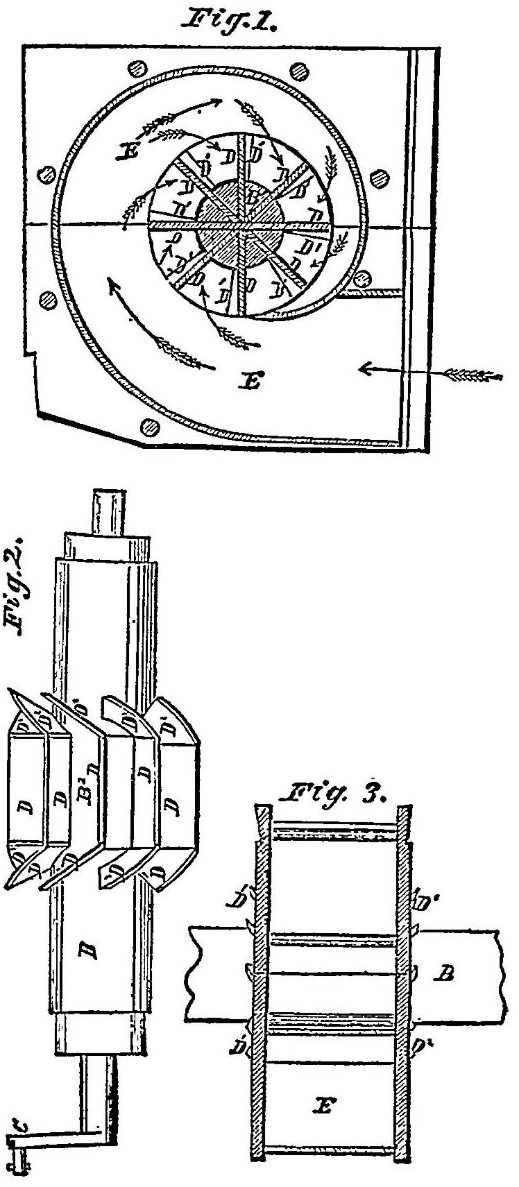
NOTE. Fig. 1. is a vertical section through the center of the wheel and scroll case. Fig. 2. is a longitudinal view of the wheel detached from the case. Fig. 3 is a transverse section at the line xx of Fig. 1. A is the bulkhead; B the shaft; C the crank; B2 is the core. The buckets D are each made of three planes: 1st. A middle plane, D, which is parallel with the axis of the shaft, radiates from the circumference of the core, and is of any required length and breadth; 2d. Two inclined end planes, each end plane inclining in an opposite direction to the other, upward toward either end of the shaft, or standing at an angle of forty-five degrees, with a plane passing through the center of the shaft, lapping over every preceding bucket about one and one-half inch, contracted at the outlet and widened at the verge. He is the scroll case through which the water passes. The supply of water from the flume is regulated by a vertical sliding gate. The width of the scroll should be equal to the length of the buckets and closed at both ends by scroll ends, causing the water to be forced toward the center of the wheel and to escape to the right and left through two sets of inclined issues. The water admitted from the flume passes into and through the scroll case in the direction of the arrows, acts upon the radial portions, D, of the buckets, by percussion, and on the inclined ends, D1 D2 of the buckets, by reaction, escaping from the ends of the wheel, causing the wheel to turn vertically in a contrary direction from that at which the water escapes, and in the same direction at which it first strikes the middle of the buckets. The improvement claimed was the construction of the buckets (radial) marked D, with inclined plane ends, D1 D, diverging in contrary directions, in combination with the spiral or scroll case E, for condensing the water and causing it to act by percussion and reaction.
1 [Reported by Hon. John McLean. Circuit Justice. The syllabus is taken from 1 Fish. Pat. Rep. 319.]
2 [From 1 Fish. Pat Rep. 319.]
2 [From 1 Fish. Pat Rep. 319.]
This volume of American Law was transcribed for use on the Internet
through a contribution from Google. 