Case No. 7,857.
KITTLE v. MERRIAM.
[2 Curt. 475.]1
Circuit Court, D. Massachusetts.
Oct. Term, 1855.
PATENTS—ERROR IN SPECIFICATION.
In construing the specification of claim in letters patent, the entire specification and drawing are to be examined, and though there is an error in showing how a particular element enters into the combination claimed, if the residue of the specification and the drawing afford means to correct this mistake, it does not avoid the letters patent.
This was an action [against Joseph H. Merriam,] on the case for the infringement of letters patent [No. 9,765,] granted to the plaintiff on the 7th day of June, 1853, for an “improved door-fastening.” The specification was as follows: “To all Whom it may Concern: Be it known that I, Samuel P. Kittle, of Buffalo, in the county of Erie, and state of New York, have invented a new and improved mode of fastening or locking, doors, so that they cannot be opened or unlocked from the outside, which I term a traveller's lock; and I do hereby declare that the following is a full, and exact description thereof, reference being had to the accompanying drawings and to the letters of reference marked thereon. The nature of my invention consists in providing the door rebate with a metal bar sufficiently thin to allow the door to shut. Said bar is of stiff metal, and provided with an edge or edges, spur or spurs at one end, which edge or edges, spur or spurs, are pressed into the wood forming the rebate, by closing the door or otherwise, and the said edges or spurs are prevented losing their hold in the wood by means of the edge of the door resting against the bar or a cap which is used in connection with the bar when the door fits badly. The other end of said bar, which projects beyond the face of the door when closed, is provided with a stop or rest, which, when the door has been closed as above, is made to bear on the face of the door, thus securing it, so long as the edges or spurs do retain their hold in the rebate. To represent and set forth more clearly the nature of my invention, I will proceed to describe its construction and operation.
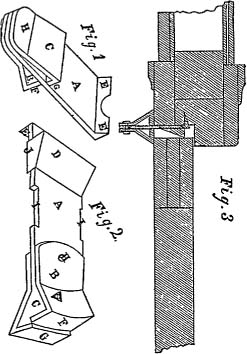
“I construct my traveller's lock of any metal or composition that does not break or bend easily. Figure 1, is a perspective view of the lock closed, with the edges up, exposed to view. Fig. 2, is a perspective view of the lock open, with cap on. Fig. 3, represents the application of the lock in a section of a door and casement which are cut through the centre of the lock.
“Let the same letters represent the same 700parts in the above figures—then A will represent the bar or stop; B the stop or rest; O the brace or guide, and D the cap. There are no necessary exact dimensions for either of these parts, provided all agree together, but it is found convenient to make the bar A 2½ inches long, 1¼ inches wide, and ⅛ of an inch or less thick, with the end that is to be inserted between the edge of the door and face of the rebate bent back at an angle of about ninety degrees from a line with the face of the bar to form the edge or edges EE, as seen; or it may be made one continuous edge, or cut into numerous pricks like saw-teeth; or there may be spurs set into the bar; or there may be a separate plate with similar device made so as to admit of a connection with the bar A, any of which would not materially alter the principle or design of the lock. 11, on the bar in figure 2, represent gains in the edges of the bar where the cap D is put on or taken off. The end of the bar A, which projects beyond the rebate and face of the door when closed, must be provided with a stop or rest, which is or can be connected with the bar A, and made to bear on the face of the door when closed; this it is found convenient to do by the rivet H, which, when used, will secure together the bar A, the stop B, and the brace C, and allow either or both the stop and brace to be thrown around back, as seen in Fig. 2; in place of the rivet, the bar and stop may be hinged together, or connected by ratchet and spring or screw, or in any way that will allow the stop to be taken off or thrown back to admit the door. The stop B may be made of like material, and same width and thickness of the bar A. The brace or guide C, as seen, is of like material with the bar A, and secured to it by the rivet H, the lip G, which is formed by bending the end of the brace so that it will stand when closed at about a right angle with the back of the bar A. The brace C acts as a guide in setting the lock into the rebate, and is also a brace to strengthen the bar A. The lip F, as seen, can be formed on the stop B by bending the material either out or in, so that it will stand at about a right angle with the face of the bar A when closed, as seen in Fig. 1, and as shown in Fig. 3. This mode saves unnecessary metal and bulk. The lip should be of circular form, the rivet being the centre when used as here represented, so that after the spurs have been secured in the rebate and the door closed, the stop B may be brought around and pressed upon the face of the door, securing it closely. The cap D, as seen in Fig. 2, is simply a piece of metal of wedge form to be used when the door does not fit closely into the rebate, as shown in Fig. 3. This cap may be connected with the bar A in various ways; it has been found convenient to do this by lips J J, as seen in Fig. 2. These lips are simply bent over the edge of the bar A, or made to fit it so that the cap may be taken off at 11, when not required. What I claim as my invention, and desire to secure by letters patent, is the combination of the bar A, having the edges E E, with the stop or rest B, having the lips F and G constructed and arranged as described. I further claim the combination of the cap D with the bar A, the effect of the cap being to fill up the space between the edge of the door when closed, and the casing as described, all for the purposes and constructed in the manner substantially as set forth in the accompanying specifications and drawings. Samuel P. Kittle.
“Arthur W. Jones, James Sangster, Witnesses.
“Patent dated June 7, 1853.”
The drawing annexed showed that the lip G was turned on the end of the brace C. The summing up was erroneous in calling the lip G a part of the rest B, and it was objected that this error was fatal to the claim.
Causten Brown, for plaintiff.
Mr. Giles, contra.
CURTIS, Circuit Justice. I disclaim, altogether, the power to correct a mistake in letters patent. The power to do this is confided by congress to the commissioner of patents, under the 13th section of the patent act of July 4, 1836 (5 Stat 122). My duty is to construe the specification and claim as they stand, and determine the legal effect of the claim. In doing this, one material thing to be adverted to is, what was in point of fact the invention. For there is a reasonable presumption that the intention of the inventor was, to obtain, and of the government to concede to him, the exclusive right to what he actually invented. Now it is conceded that the brace C, with its lip G, are essential parts of the invention; and it is therefore fairly to be presumed he intended to embrace them in his summing up. Still, he may have failed to do so, and we must look at the language employed and see whether he has or has not included these parts in his summing up. Referring to the terms used in the claim, it is not doubtful that the patentee intended to include in his combination the lip G. He says so in express terms. No doubt exists on this subject. The doubt arises from the terms employed to show how the lip G is to come into the combination. Taken by themselves, the words and letters of a part of the claim indicate that the rest B has two lips, F and G, and that the lip G enters into the combination as part of the rest B. But in construing a claim we cannot look to a single phrase only, to the exclusion of all the residue of the writing. On the contrary, we must look at the entire specification and drawings, and view each part by the light thrown on it by the whole. If the specification, taken as a whole, leaves no reasonable doubt concerning the intention of the patentee to include in the combination claimed, the brace and its lip G, then it is to 701be considered as included. It has already been stated that even the words of the claim relied on by the defendant, show that the lip G enters into the combination; and the close of the claim also shows that the parts of which the combination consists are to be combined and arranged, that is, introduced into the combination, substantially as is described. And the description and drawings clearly show, that the lip G is to come into the combination as part of the brace O, and that it is only in that way, it can possibly be combined with the other parts. The case, then, is this—the lip G is to come into the combination. One part of the claim says as one of the parts of B; another part of the claim, taken in connection with the residue of the specification and drawing, says it is to come in as part of C. And no reasonable man can doubt that the latter and not the former is what the patentee really intended. The rule of “error demonstrationis non nocet” is, therefore, applicable. We may reject the erroneous description, and have enough left clearly and certainly to identify the mode in which the lip G was to enter into the combination claimed. The parties then went to the jury upon the questions of novelty and infringement, and the defendant had a verdict.
1 [Reported by Hon. B. R. Curtis, Circuit Justice.]
This volume of American Law was transcribed for use on the Internet
through a contribution from Google. 