Case No. 7,838.
KIRBY et al. v. DODGE & STEVENSON MANUF'G CO. et al.
[10 Blatchf. 307; 6 Fish. Pat. Cas. 156;1 3 O: G. 181.]
Circuit Court, N. D. New York.
Dec. 30, 1872.
PATENTS—“GRAIN HARVESTERS”—EVIDENCE—REISSUE.
1. The state of the art prior to the date of the alleged invention of Byron Densmore, embraced in letters patent granted to him February 10th, 1852, for an “improvement in grain harvesters,” set forth. In that patent, Densmore does not claim shifting the position of the axle of the main wheel, relatively to the height of the cutter frame, nor placing the main wheel in one frame and the cutter, or platform and cutter, on another, nor hinging the cutter frame and the wheel frame together, so as, by the action on the hinge, to effect the raising or lowering of the cutter. Such omission to claim, in that patent, anything in respect to using two frames, or hinging one frame to the other, is evidence, when the novelty of the device is in dispute, that Densmore was aware that he could not claim to be the first inventor of anything more than the special arrangement, or relative position, of the parts.
[Cited in Wheeler v. McCormick, Case No. 17,499.]
2. The question, whether the first claim of the reissued patent granted to William A. Kirby and others, January 28th, 1862, on the surrender of the said patent of 1852, and extended, January 30th, 1866, for seven years from the 10th of February, 1866, namely, “Hanging the driving wheel in a supplemental frame, or its equivalent, which is hinged, at one end, to the main frame, while its opposite end may be adjusted and secured at various heights, or be left free, as desired, whereby the cutting apparatus may be held at any desired height for reaping, or be left free to accommodate itself to the undulations of the ground, for mowing, substantially as described,” can be sustained, if construed so as to embrace anything except the special and specific arrangement described and shown in the original patent, with its specifications, drawings and model, is not, upon the facts in this case, concluded by the decision in Whiteley v. Kirby, 11 Wall. [78 U. S.] 678.
[Cited in Worswick Manuf'g Co. v. City of Kansas, 38 Fed. 241.]
3. If such claim be regarded as a broad claim to hinging the frame of the cutters to the wheel frame, and making it adjustable by changing the relative elevation of the two frames, it is not new.
4. If such claim be regarded as claiming a device to permit the cutters to vibrate, so as to follow the undulations of the ground, when in use, it is invalid, for the reason that Densmore had not invented any such device when his original patent of 1852 was granted.
5. The obtaining of such reissue was an attempt to extend the original patent over a feature which it did not embrace, and which the patentee had not conceived when he obtained that patent.
6. The defendant's machine held not to infringe the first claim of said reissue, construed as claiming the specific arrangement of two frames in the position and mode of operation described in the specification.
2 [Final hearing on pleadings and proofs.
[Suit brought on letters patent [No. 8,720] for “improvement in grain harvesters,” granted to Byron Densmore, February 10, 1852, assigned to D. M. Osborne and William A. Kirby, and reissued to them January 28, 1862, as No. 1,262, and extended for seven years from February 10, 1866.
[The main question in the present case related to the interpretation to be given to the first claim of the reissued patent. The same patent had been before the courts in the case of Kirby v. Whitely [unreported], in the circuit court for the Southern district of Ohio, in 1866, and in the same case on appeal to the supreme court of the United States. 11 Wall. [78 U. S.] 679. The reissue was sustained in both cases.
[The specification of the original patent was as follows:
[“To all to whom these presents shall come: Be it known that I, Byron Densmore, of the town of Sweden, in the county of Monroe and state of New York, have invented a new and useful improvement in reaping-machines, for cutting wheat and other small grain, and I do hereby declare that the following is a full, clear, and exact description of the construction and operation of the same, reference being had to the annexed drawings, making part of this specification, in which Fig. 1 is a perspective view of the machine; Fig. 2 is a vertical longitudinal section, through the driving-wheel, showing the reciprocating lever, the springs, the cords that connect the reciprocating lever to the rake, the pulleys that conduct the cords and teeth of the rake; Fig. 3 is a view of the platform with the covering of the rake removed, showing the finger-piece and fingers, the sickle, the plates that support the sickle, the parallel-rods on which the rake vibrates, the rake, the attachment of the cords to the rake, the pulleys, the crank on which the small ground-wheel is hung that carries the left side of the machine and the winch for adjusting said crank; Fig. 4 is a view of the outer side of the grooved cam, showing the ratchet-wheel, the hand and spring that holds the hands into the ratchet-wheel; Fig. 5 is a vertical longitudinal view of the plates that support the sickle; Fig. 6 is a view of the back tooth of the rake. My invention and improvements consist in a new arrangement for raking the grain from the machine, likewise in a new arrangement for raising and lowering the machine to vary the height of the cut; also in a new mode of hanging the sickle, which will be particularly described. The same letters indicate like parts in all the figures. The finger-piece H is made fast to the parallel hounds A and a; to these hounds the tongue is attached. The team is harnessed to the tongue in the usual manner. The frame B and b is attached to the hounds A and a, a few inches in front of the finger-piece, by straps of iron, as at C, Fig. 2; these straps of iron are bolted to each side of the hounds, and extend up on the sides of the 662ide-pieces of the frame, and a bolt passes through the tops of these straps, and through the side-pieces of the frame B and b, and from a hinge; the front end of the frame is fastened to the upright pieces D, D, by bolts, and these bolts are shifted into different holes in these upright pieces, to vary the height of the cut. The seat for the driver is formed on the upright pieces. The axle of the driving-wheel, E, E, has its bearings on the side-pieces of the frame B and b, so far back as only to leave room for the driving-wheel to run clear of the back cross-piece of the frame; to the center end of the axle of the driving-wheel, is attached a master-spur cog-wheel, that meshes into a pinion in front of it, which is hung on a short arbor that has one of its bearings on the under side of the side-piece b of the frame, and the other bearing on the under side of a piece of timber framed parallel to the side-piece b, and about eight inches outside of it. Outside of the spur-pinion, on the same arbor, is a bevel cog-wheel, that meshes into a pinion that is hung on an arbor which has its bearings on the cross-girts of the frame, and extends back of the frame; on the back end of this arbor is hung a small fly-wheel, that has an inner wrist through the plane of it, about two and three-eighth inches from the center, which forms a crank that drives the sickle; to this pin or wrist is attached a rod or pitman, which is connected to the sickle d, d, d, d, Fig. 3. The sickle, instead of resting upon the fingers e, e, e, e, e, e, e, e, e, e, in the usual way, for support, is supported by the iron plate f, f, f, Figs. 3 and 5; these plates are made fast to the edge of the finger-piece H, and project in front of it, say two and one-half inches, and thus form a bearing for the sickle or blade in sections, separate from the fingers, and the fingers are so shaped as not to touch the sickle more than one-fourth of an inch back of the cut, but are grooved out in the rear or under the back part of the sickle, say one-fourth of an inch, thereby preventing choking, by giving the straws room to slide or drop out. The small ground-wheel F, that carries the left side of the machine, is hung on the crank h, Figs. 1 and 3, which is supported by boxes on each side of the wheel, made fast to the frame, G, G; the center end of this crank, or its shaft, is made square, and the holes in the end of the lever g are fitted to it, one diamonding and the other square. To vary the height of the cut, at the left side of the machine, the lever g is taken off from the crank, and shifted as desired, and then fastened down to the frame, at g. The grooved cam M is hung on the inner end of the axle of the driving-wheel, and is made to turn upon it like a loose pulley, and is made to revolve with the driving-wheel, when necessary, by the hand I, Fig. 4, holding in the ratchet-wheel I. The circular spring T holds the hand into the notches of the ratchet-wheel, and prevents it from falling out when it passes the under side. The friction roller k, Fig. 2, works on the groove of the cam M; it is attached to the reciprocating lever k, at I, Fig. 2; the lever is attached to the frame, say fifteen inches in front of the friction roller, at 2, by means of a plate of iron, which is bolted to the under side of the lever K; this plate has bearings projecting out each side of the lever, to which are fitted boxes that are bolted to the frame, forming a hinge, on which the lever vibrates; the front end of this lever is turned upward and extends forward of the point of attachment to the frame, say fifteen inches, as at 3, Fig. 2, and is attached to the spring m, in the manner hereinafter described. As the grooved cam M revolves, the friction roller K is moved downward from I to 4, Fig. 2; and the lever K is moved downward with it, and the back end of the lever K is made to pass down from 5 to 6, a distance equal to the length of the platform G; then the friction roller K presses against the inner flange r, r, of the cam, and the lever is forced back to 5 again. To the back end of the reciprocating lever K, is attached the three cords, but chains or straps may be used. Two or three cords pass down at 7, 7, Fig. 2, around the pulley o1, along the end of the platform, and one of them turns around the pulley o2, Fig. 3, and is attached to the back end of the rake at P, Fig. 3; the other cord passes around the pulley o3, and is attached to the end of the rake nearest the finger-piece; these cords are attached to small blocks of wood, P, at p, Fig. 3; these blocks have holes through them, fitting the parallel-rods Q, Q, at q, q, and slide on these rods. The third cord passes upward and around the pulley o4, thence to the pulley o6, Fig. 1, then to the pulley o8, and-is attached to the center of the rake at 8, Fig. 3. This cord being then attached as the reciprocating lever K descends from 5 to 6, the rake is made to slide across the platform, from right to left, on the parallel-rods Q, Q, and q, q. The rake is made by putting a rod s, s, of half-inch round iron, say two feet long, through the corresponding holes in the blocks P and p, at right angles with the parallel-rods Q, Q, and q, q, to this rod s, s; the teeth f, f, f, Fig. 2, of the rake, are attached to the lower end of the back rake; tooth f1 is made to extend a little below the transverse rod s, s, to which the rake-teeth are attached as at 2, Fig. 6. When the rake passes from right to left across the platform, the teeth turn down the upper ends to the platform, and when it comes to the left side the lower end of the back tooth f1 strikes the small hook at 9, Fig. 3, and the teeth raise up, and they are prevented from falling down, while they pass to the right side of the machine, by the pressure of the grain against them. In ease the pressure of the grain comes wholly against one tooth, as it is liable to, the rake is prevented from turning, and one end getting ahead of the other, and thus cramping 663on the rods on which it runs, by the manner the cords are attached to it; the two cords that move it from left to right being attached to each end of the rake, and the one that moves it hack being attached to the center. The grooved cam is so formed as to move the rake from left to right across the platform, with about three times the velocity that it moves from right to left; consequently the grain is discharged at the right side of the machine with great motion. It is necessary to have the rake so arranged that the gavels can be left at different distances apart in thin and thick grain, that the gavels may be at all times of suitable size for binding. This is effected by planing the small lever R, on the top of the side-piece B, of the frame; the back end of it is above the center of the ratchet-wheel, and turned in toward it; the forward end of it extends forward to the driver's seat; it is attached to the side-piece of the frame by a bolt about five or six inches from the back end, on which it turns. The back end of the lever is held up to the ratchet-wheel by a spring, and as the hand I, Fig. 4, comes to the upper side, it strikes against the back end of the lever and is thrown out of the notches of the ratchet-wheel, and the rake stops. The rake at this time is at the left side of the platform always, and the rake stands still until the driver presses his leg against the front end of the lever R, and bears it inward, which throws the back end out from under the hand, and the rake is put in motion; or the rake may be made to throw off the grain any given distance between one and two revolutions of the driving-wheel, by pins projecting out from the plane of the ratchet-wheel, which could be so arranged as to throw out the back end of the lever from under the hand, and put the rake in motion after it had been stopped a quarter, a half, or a whole of a revolution of the driving-wheel—that is, four such pins placed on the four quarters of the ratchet-wheel, would not allow of the rake being stopped but one-fourth of a revolution of the driving-wheel; two would not allow of its stopping but one-half of a revolution, and one would allow it to be stopped one entire revolution before it would be put in motion again. The hand Y is used for the purpose of preventing the cam M from turning backward when the hand I, Fig. 4, is raised out of the notches of the ratchet-wheel i. It is made fast to the inside of the side-piece B, of the frame, and catches in the notches of the ratchet 2, Fig. 4. The grain being raked off from the machine with a quick motion, it is desirable to have some means of accumulating power while the rake is returning from right to left, to assist in throwing off the grain. For this purpose the front end of the lever K is attached to the spring m. As the back end of the lever K is forced downward, the front end ascends and draws the spring toward the frame. The spring m is made very stiff. Now, as the back end of the lever K moves upward and moves the grain on the platform, the spring pulls downward on the front end of the lever with great power, thus relieving the pressure on the cam M very much. But it is evident that if the chain T was attached to the front end of the lever K, and to the spring M, directly, the spring would exert a much greater power on the lever where it was drawn upward to its highest point, than when it was down to its lowest point, and the spring would be springing a distance equal to the space the front end of the lever passed through. To avoid these objections the double eccentric U is used. It is a piece of cast-iron, with a one-half inch iron rod passing through it, on which it turns as an axis. This rod is supported by two irons that project out in front of the frame B, b. The chain T is attached to the front end of the lever K, and to the largest eccentric at the point farthest from the axis, and the chain Y is attached to the end of the spring m, and to the smallest eccentric at the point farthest from the axis, and these chains are so arranged on the eccentric that, as the one winds on, the other unwinds, vice versa; and the eccentrics are so arranged that as the front end of the lever K ascends, the line of draft of the chain T is thrown off farther and farther from the axis of motion of the eccentric, while at the same time the line of draft of the chain Y comes nearer and nearer the axis. Thus, the power to move the springs, or the leverage on it to move it, is increased as the spring becomes stiffer, by being drawn toward the frame, and the circumference of the eccentric on which the chain T winds, is about double the circumference of the one that the chain Y. winds on. Hence the spring only about half the distance of the front end of the lever K, moved by this arrangement: the power of the spring on the lever is made equal in all positions or raised, as may be desired. The reel W is made, supported, and operated in the usual manner. The board X is attached to the divider Y, by a hinge-joint, that it may be raised and lowered with the reel and kept at all times so that the arms of the reel will but just clear it, that grain may not lodge upon it There is a wire, not shown in the drawings, running down from the board X, obliquely to the platform, in front of each rake-tooth, to keep the grain clear of the rake-teeth while they are raised up.
[“What I claim as my invention, and desire to secure by letters patent, is: 1. The combination of the grooved cam, M, and reciprocating lever, K, so arranged with each other as to give to the rake, while in the act of clearing the platform of grain, an increased rapidity of motion as compared with its backward movement 2. Controlling the motion of the rake by means of the combined action of the hand I, ratchet i, and lever R, as set forth. 3. The arrangement 664of the double eccentric U, for equalizing the power of the spring M on the lever K, in the manner described. 4. Forming supports for the vibrating blade or sickle by the plates f, f, f, in sections separate from the fingers, to prevent choking, as described and represented. Byron Densmore.
[“Witnesses:
[“Hiram Moore.
[“L. Burrows.”
[The specification of the reissue was as follows:
[“To all whom it may concern: Be it known that Byron Densmore, of the town of Sweden, in the county of Monroe and state of New York, assignor to David M. Osborne, of the city of Auburn, and William A. Kirby, of the city of Buffalo and state aforesaid, heretofore invented certain new and useful improvements in harvesting-machines: Now, therefore, we, the said David M. Osborne and William A. Kirby, assignees of the whole interest of the said Byron Densmore, as aforesaid, do hereby declare that the following is a full, clear, and exact description of the construction and operation of the said invention and improvements, reference being had to the accompanying drawings, making a part of the specification, in which Fig. 1 is a perspective view of the machine; Fig. 2 is a vertical longitudinal section on line x, y, of Fig. 3; Fig. three (3) is a top plan of the machine; Fig. 4 is a vertical longitudinal section through the driving-wheel, showing the combination of the main and supplemental frames; Fig. 5 is a view of the outside of the grooved cam, showing also the ratchet-wheel; Fig. 6 is an elevation of the guard-finger; Fig. 7 is a section of a plate or secondary finger, placed intermediate between a portion of the guard-fingers, to support the sickle or cutters; Fig. 8 is a view of the back tooth of the rake; Fig. 9 is a view of the outside ground-wheel. The nature and principles of the said invention relate: 1. To the construction and combination of two frames—the one for supporting the driving-wheel, and the other for supporting the cutting apparatus, and hinging the said frames together in such a manner that the driving-wheel and cutting apparatus may each follow the inequalities of the ground independently, and also that they may be bolted rigidly together, for supporting the cutting apparatus, at any desired height. 2. In providing a ground-wheel, with crank and lever, for raising and lowering the end of the finger-bar. Letters of like name and kind refer to like parts in each of the figures.
[“I represents the main frame of the machine, which consists of several pieces of timber properly framed and bolted together. This frame carries the finger-bar and cutting apparatus as herein described. P are two upright posts, forming part of the main frame, for the purpose of supporting the driver's seat, and for forming an adjustable connection with the supplemental or wheel-frame. O represents a supplemental frame in which the driving-wheel is hung. It is hinged to the main frame by means of bolt and hinge-plate, as shown at d, so as to allow it to have a hinge or joint-like connection between the two frames, so as to allow an independent movement of each frame. The particular manner of forming the hinge or joint connection is not deemed important; any mechanical means by which the end is secured will answer the principle of the invention. The opposite end of the frame moves on the arc of a circle, and in close proximity to the upright posts C, so that it may be made fast to said posts by means of bolts passing through said posts and frame at either of the several bolt-holes v″, by which means an adjustability is secured, and the cutting apparatus thereby raised and lowered, and supported at any desirable height from the ground when reaping. When desired, the adjusting bolts may be removed entirely, and this end of the frame left free to oscillate or swing from its hinges according as the unevenness of the ground over which the driving-wheel passes may require. By this combination and connection of the frames it is evident that the driving-wheel, when moving, may pass over uneven surfaces without causing an elevation or depression of the finger-bar and cutting apparatus; and the finger-bar and cutting apparatus may also conform to the inequality of the ground, independently of the position of the driving-wheel, and a uniform flexibility between the two frames constantly maintained, the elevation or depression of the driving-wheel, and the elevation and depression of the cutting apparatus, occasioned by the uneven surfaces of the ground over which the machine passes, not being simultaneous or dependent one upon the other. The axle of the driving-wheel has appropriate bearings upon the side-pieces of the supplemental frame, as shown at e, Fig. 3. The gear-wheels, communicating motion to the cutters, as shown at 1, 2, 3, 4, each hung in a common manner upon its appropriate shaft, as shown in Fig. 3.
[“The ground-wheel F, shown in Figs. 1, 3, and 9, is hung on the crank h, which crank is supported by boxes on each side of the wheel, made fast to the wheel G; or it may be supported on the finger-bar or divider in any convenient manner, so that the wheel may be made to adjust and carry the outer end of the finger-bar as desired. One object of hanging this wheel on a crankshaft, with a lever attachment thereto, is to provide a means of conveniently raising and carrying the outer end of the cutting apparatus free from the ground when it is desirable to move the machine from place to place. Another object is to afford the means for raising, lowering, and supporting the outer end of the finger-bar and cutting 665apparatus at different heights from the ground when the machine is used for reaping. The essential feature of this part of the invention is hanging the wheel upon a crank-shaft, with the crank and lever for operating the same; so that the purpose of raising and lowering the outer end of the finger-bar is attained, the precise details of the arrangement are not deemed important. The finger-bar, H, is made fast to the side-pieces of the main-frame, upon the upper side of the said pieces, by bolts or otherwise, as shown at a; so that the inner side-piece will serve as an extension shoe or runner to slide over the stubble or mown grass, and protect the heel of the cutters, 11n, driving-wheels. Z, draught-pole attached to the main frame, and to which the team is harnessed in the common manner.
[“Having thus fully described the construction and operation of the said improvements, what we claim as the invention of the said Byron Densmore: 1. Hanging the driving-wheel in a supplemental frame, or its equivalent, which is hinged at one end to the main frame, while its opposite end may be adjusted and secured at various heights or be left free, as desired, whereby the cutting apparatus may be held at any desired height for reaping, or be left free to accommodate itself to the undulations of the ground for mowing, substantially as described. 2. The employment, in a harvesting-machine, of a wheel provided with a crank and lever for the purpose of raising and lowering the outer end of the finger-bar to cut high or low, substantially as described. David M. Osborne.
[“Wm. A. Kirby.
[“Witnesses:
[“Chas. Garlock.
[“John H. Osborne.”
[The drawings attached to the original and reissue were substantially the same.
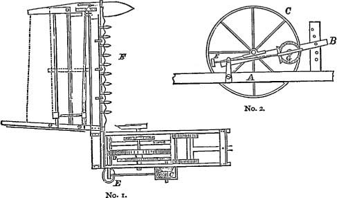
[The foregoing engravings represent two figures of the reissue; No. 1 being a top view of the Densmore machine, and No. 2 a vertical longitudinal section through the driving-wheel, showing the combination of the main and supplementary frames. It will be observed that the lower frame, marked A, carries the finger-bar and cutting apparatus. The upper frame, marked B, is hinged to a post rising from the lower frame, and carries the driving-wheel and gearing. At the opposite end it is held at any desired height, by a pin passing through holes in an upright. The distance of the two frames from each other, and, consequently, of the cutting apparatus from the ground, may be varied by changing the position of the pin.
[The complainant claimed that by leaving the pin out altogether, the lower frame would be free to vibrate, or move up and down, to accommodate itself to the undulations of the ground, in mowing grass.]3
David Wright, for complainant.
George Harding, for defendant.
WOODRUFF, Circuit Judge. The complainants herein complain that the defendants have infringed, and are infringing, their rights, as assignees of a certain patent granted to Byron Densmore, on the 10th of February, 1852, for a new and useful “improvement in grain harvesters,” surrendered and reissued to the complainants January 28th, 1862, and thereafter, on the 30th of January, 1866, extended for the term of seven years from the expiration of the first term, namely, from the 10th of February, 6661866. The defendants deny that Byron Densmore was the first inventor of the improvement described in the reissued letters patent, and aver that such reissue was fraudulently and illegally granted, and was obtained in order to include, and does include, things not invented by Densmore, and not intended to be patented by him, and that such reissued letters patent are for a different invention from that originally patented, and are invalid and void. They also allege, that the improvement described in the reissued patent had, prior to February 10th, 1852, been invented, and was known and used by other persons, who are named in the answer; and that it was described in certain letters patent, also mentioned. They also deny that they have made or sold any machines whatever containing the said alleged invention of the said Densmore, as set forth in the specification, and specified in either of the claims, of said reissued patent, and deny that they have in any manner whatsoever infringed the said letters patent.
The infringement alleged relates solely to the first claim in the reissued patent granted to the complainants. “The nature and principle of the invention” included in that claim are declared, in the specification, to relate “to the construction and combination of two frames, the one for supporting the driving wheel, and the other for supporting the cutting apparatus, and hinging the said frames together, in such a manner that the driving wheel and cutting apparatus may each follow the inequalities of the ground independently of the other, and, also, that they may be bolted rigidly together for supporting and cutting apparatus at any desired height.” The claim, with which the patentees conclude their description of the construction and mode of operation of the improved machine, is as follows: “Hanging the driving wheel in a supplemental frame, or its equivalent, which is hinged, at one end, to the main frame, while its opposite end may be adjusted and secured at various heights, or be left free, as desired, whereby the cutting apparatus may be held at any desired height, for reaping, or be left free to accommodate itself to the undulations of the ground, for mowing, substantially as described.”
Prior to Densmore's alleged invention, reaping machines had been made by McCormick, and others, consisting of a large wheel bearing on the ground, surrounded by a rectangular frame, in the sides of which the axle of the wheel turned, and at the end of which the platform and cutting apparatus was attached, that cutting apparatus extending sidewise from this frame to the distance or width of the swath of grain proposed to be cut. Gearing was connected with the ground wheel, and operated by its revolution, when drawn over the ground, upon arms, swivels, and rods, which moved the cutters and severed the grain, which, when severed, fell upon the platform, and was raked off into gavels. As a machine so constructed was liable to tilt sidewise, and, under the weight of the platform and cutters projecting sidewise, must necessarily tilt sidewise, a small wheel was also placed at the outer end of the platform and cutter-bar, which sustained the cutters, and, if the ground was level, also sustained the frame, to the end of which the platform was attached, and in which frame the axle of the main wheel was placed, and so prevented the tilting or upsetting of the machine. This involved, also, another necessity in the construction, namely, the platform and cutters must be rigidly attached to the frame, else, the smaller wheel at the outer end could not operate to support the frame, or the wheel moving therein, and to prevent the tilting referred to. There were, perhaps, other reasons why the platform must, in such a machine, be attached with great firmness and strength, but it is sufficient for my present purpose, to make the general construction of the machine intelligible. Densmore had seen one of McCormick's machines, in which, in order to raise or lower the cutters, there were two or more holes in the side pieces of the frame, in either of which the axle of the main wheel could be placed, and, by the change, the height of the cutters from the ground would be varied. Densmore, instead of relying upon such holes for inserting the axle in the side pieces of the frame, which must, I think, have been inconvenient to change, made a model in which he inserted uprights, with long curved tenons, in mortices, in the sides of the frame, at the place of the axle of the wheel, and inserted the axle of the wheel therein, and so, by raising those uprights in the mortices, and depressing them, at pleasure, a similar effect, to raise or lower the cutters, was produced. In view of this change of construction, as well as other devices, Densmore, on the 3d of June, 1849, filed a caveat in the patent office. Long prior to this, McCormick made numerous machines, wherein the cutters could be raised and lowered, so as to cut at different heights, by another device, which will be hereafter noticed. Densmore, however, took out no patent for the machine as described in his caveat. He made a model, in which he placed a second rectangular frame upon the other, and of somewhat less length. Near the middle of this he placed the axle of the main wheel, with the gearing connected therewith. Obviously, such additional frame, when lying flat upon the upper surface of the other, amounted simply to giving the side pieces of the latter greater width, but, for facility in raising or depressing the cutters, by lowering the frame to which they were attached, he attached one end of the upper frame to the lower frame by a hinge, so that, (acting on the axle of the wheel 667as a fulcrum,) by raising and lowering the other end of it, he lowered and raised the lower frame beneath the axle of the wheel, producing the precise effect before caused by raising and lowering the long tenoned uprights into and from the mortices before mentioned; and, at the forward end of the upper frame, he set, in the lower frame, uprights, to which that forward end was bolted, at any desired elevation, by bolts, easily removed and inserted in holes, higher or lower, in the uprights, at pleasure. It was this machine, imperfectly described, perhaps, but this in substance, that was shown in the model and drawings, when he took out his patent, in 1852. In these descriptions, I, of course, omit notice of devices for raking and reeling, and for adjusting the outer or platform wheel, because they are not material to any question now in issue.
McCormick had, as early as 1835, employed the other device, (above alluded to,) for raising and lowering the cutters, so as to cut at different heights. He placed his main wheel, with the gearing connected therewith, in one frame, and the platform and cutters were fastened to another frame, the sides of which were not laid upon nor placed beneath the other, but ran along the sides, parallel therewith, so as to embrace the rear ends thereof. The sides of both of the frames were attached by a bolt passing through them, as a pivot or hinge, so that the cutter frame, turning on that pivot, could be raised or lowered, at pleasure. At the forward ends of the arms of the cutter frame, three holes were made in the wheel frame, at different heights, through which to bolt the cutter frame, and fix it in the several positions which raising or lowering the cutters required, and it was entirely practicable, by withdrawing the last mentioned bolt, to permit the platform and cutter, or rather the ends of the supporting cutter frame, to rest upon the ground. Whether, when so resting on the ground, the machine was a practical machine, useful for mowing, it may be material hereafter to consider. For the present, I describe the machine.
Passing by what is claimed by the defendants to have been done by others, and omitting to further describe the state of the art, I have mentioned what had been done by McCormick before 1852, and what Densmore did prior to the granting of his original patent of February 10th, of that year. He then received his patent, and it is of some significance, that, in his specification, he in no wise claims that shifting the position of the axle of the main wheel, relatively to the height of the cutter frame, is new, nor that placing the main wheel in one frame and the cutter, or platform and cutter, on another, is new, or that hinging the cutter frame and the wheel frame together, so as, by the action on the hinge, to effect the raising or lowering of the cutter, is new. Obviously, with McCormick's machine before him, he could not broadly claim either of these. The utmost he could claim, if anything, on these several points, was the particular device by which these operations were performed, in so far as it differed substantially from McCormick's. Possibly, the placing one frame above another, to be operated in the manner I have attempted to describe, and as shown in his drawings and model, was patentable. But, in fact, he made no claim even to this. His claims were confined solely to other devices, to assist in raking the grain and supporting the blades of the cutters. He does state that his arrangement for raising and lowering the machine, to vary the height of cut, is new; and that is entirely consistent with what is above stated. McCormick's arrangement of the parts employed in this operation was not identical with his. In function, and effect, and mode of operation, they did not differ, but, in arrangement or relative position, they were unlike. I mention this omission to claim anything in respect to using two frames, or hinging one frame to the other, not because a patentee may not claim in a reissue what, through mistake or inadvertence, he did not claim in his original patent, but, because it is evidence, when the novelty of the device is in dispute, that Densmore, when he took out his patent, was aware of what McCormick had done before him, and was conscious that he could not claim to be the first inventor, or, certainly, not of anything more than the special arrangement, or relative position, of the parts.
The foregoing explanations will, I think, make the consideration of the questions below stated intelligible—First, whether the reissued patent, if construed so as to embrace anything except the specific arrangement described and shown in the original patent, with its specification, drawings and model, can be sustained; and second, whether, if the reissued patent is valid for any, purpose, or to any extent, the defendants infringe any rights secured to the complainants thereby.
I. Upon the first question, it is insisted, by the complainants, that the decision of the supreme court of the United States, in Whiteley v. Kirby, 11 Wall. [78 U. S.] 678, is conclusive in their favor, and that this court should not assume to discuss the correctness of that decision. The decision in that case does not operate as an estoppel upon the defendants in this. Nevertheless, the decision of a question of law arising upon the same facts, is an authority which I am not at liberty, and have no disposition, to disregard. But, that case was a very different one from this in its facts, and, if I were at liberty to do otherwise, I should unhesitatingly concur in the decision of the point which was actually decided, upon the evidence which appears to have been before the court. Entertaining the views I do upon 668the question of infringement, it is not indispensable that I should consider this first question, but, in the aspect of the case which is urged by the defendants, there is no necessary inconsistency with that decision; and the observations I deem it proper to make upon this reissue seem to me conclusive against the construction of the reissue upon which the complainants rely, and in no conflict with the former case.
The machine of Densmore, described in the original patent, and shown in the specification, drawings and model, was a reaper, and not a mower. It was a machine which not only was not shown to be a mower, but, as described and shown, it had not, in fact, capacity to mow, in any sense material to this case. By no means shown or suggested could the cutters be made to follow the undulations of the ground. The terms of the specification are explicit: “The front end of the frame is fastened to the upright pieces by bolts, and these bolts are shifted into different holes in these upright pieces, to vary the height of the cut.” No terms could have been employed to state more positively, that, when in use, the front end of the frame must be bolted to the uprights. The drawings show the front ends of the frame thus bolted; the model shows the same; and there is no intimation or suggestion of the practicability of using the machine in any other condition. The patentee showed a reaper, with its platform, rake, reel, &c. To any suggestion, that it might, nevertheless, cut grass at or near the surface of the ground, the answer is—if it were so bolted as to cut grass near the ground, then it did not follow the inequalities of the surface—the vital thing to make a useful mower, and the very thing which the reissue sought to embrace.
It was not until after the granting of the original patent, that any attempt is proved to use the machine as a mower. That rests upon the testimony of the patentee, who himself shows that it was an unsatisfactory experiment, and was abandoned. Other testimony leaves even this experiment in great doubt. But, let it be assumed, for the moment, that, in the summer of 1852, Densmore did mow one acre of grass with it. When that experiment was made, the machine was changed, changed in substance, changed in its capacity, and changed in its actual functions. First, by removing the bolt which secured the ends of the wheel frame, the cutter frame was allowed to drop to the ground. Before this, the wheel frame carried the cutters; and, to that end, the frames had been, and, according to the description given in the patent, must be, bolted together; and the conception of a machine which was not so bolted, or which did not carry the cutters at an elevation (greater or less) from the ground, had not been, in any manner, indicated. Removing the bolt, and relying upon the ground to sustain the frame of the cutters, was a distinct and different device, involving a difference in mechanical construction, the performance of a different function, and a different mechanical operation. In principle, removing a bolt does not differ from adding a bolt; and, in the machine described in the original patent, that bolt was a mechanical device, performing a precise and defined mechanical office, and, according to the terms of the specification, as it was in fact, indispensable to that office. Removing this, to produce a different result, was tantamount to adding another device to the same end. An entirely distinct and different function was also thereby introduced into the machine, namely, by the oscillation or vibration of the frame, to permit the cutter frame to undulate, as the unevenness of the ground might make desirable; and, finally, the mechanical operation of the machine in the work was different in that, before, the cutters had a rigid connection with the wheel frame, and now they were to be operated through a flexible attachment thereto, and, also, in that, before, the cutting apparatus was sustained and borne by the joint action of the two frames, and now it was borne forward by the one frame alone to which it was attached. In short, it became a different mechanism in relation to the work to be performed, and in the manner of performing it. It will not do to say that it was within the scope of the original patent, because the alteration was effected by the trifling change of removing a bolt. That is not the test. Many a useful and valuable invention has been made, of a device so simple and so seemingly trifling, that men wonder that it was not made long before. The inquiry is, was such a device before known, and, in this case, also, was this device for suffering the frame of the cutters to follow the ground, in any manner indicated in Densmore's patent, or his specifications, drawings, or model? If not, then his patent does not, and cannot legally be made to, embrace it.
Again, this removing of the bolt, and thereby letting the frame of the cutters to the ground, and permitting them to be drawn along the surface, was not, of itself, a new device. It could be done, and had been done, by McCormick, in his machine. The proof shows this, and to an extent quite as great as the experiment of Densmore in mowing the single acre to which he testifies. In this, there was, no doubt, the dawn of a new conception, which has since matured, and has produced what is known as the floating finger-bar, of which there is not the slightest intimation in Densmore's record, and of which, I am satisfied, when his patent was granted, he had no idea; and, even when he tried his unsatisfactory experiment, he had no more found or shadowed that important invention, which now gives utility and value to mowing machines, than McCormick had, when, years before, his machines were used in mowing, by a similar change in their organization. In either, if a bolt was removed, 669the cutter frame was made to rest on the ground.
It is urged, that the machine of McCormick, when such bolt was withdrawn, was useless, and not a practical machine, and, in the face of the testimony to its actual use, some witnesses express that opinion. There is, at least, equal weight of evidence, that the same is true of Densmore's machine, as patented, and there is, besides, further, and, to my mind, satisfactory, evidence, that, from and after the experiment alluded to, he did not regard it as a practical machine for use, with the bolt withdrawn, and did not so treat it. It did, according to his testimony, mow one acre of grass, but his testimony also shows that the experiment was unsatisfactory; and, at least as much is proved in favor of McCormick's machine, in this respect, as of Densmore's. Several witnesses speak upon this subject, and they give a most satisfactory reason why Densmore's machine would not operate successfully when the bolt was withdrawn, and the frame of the cutting apparatus rested on the ground. The machinery by which the cutting apparatus is operated is only moved as the main wheel revolves, and the motion is effected by gearing connected with that wheel. Unless the wheel bears heavily upon the ground, it will wholly or partially slide, instead of turning. Its power to turn the gear wheels is derived from its firm hold on the ground, and, if it slide, the machinery does not operate successfully. The witnesses say, and it seems quite obvious, without proof, that, removing the bolt, and permitting the cutter frame to fall to the ground, removes from the wheel all the weight of the cutter frame and platform, and the greater part of the weight of the cutter bar, and so renders the wheel liable to slide on the ground, instead of properly turning the gear wheels and operating the cutters.
The suggestion of impracticability comes from the complainants and their witnesses. They allege, that McCormick's machine, when the bolt by which it was held in a fixed position was removed, ceased to be a practicable machine. As a reaper, and carrying the heavy platform, cutter bar and cutters, that may be so; but, if it is, then, for the same reason, and to the like extent, Densmore's machine was impracticable also. Indeed, he so testifies; and it is, I think, clear, that neither were or could be successfully used, when constructed as they were constructed and described, namely, for reaping, if the bolt was removed and the frame of the cutting apparatus was suffered to rest on the ground. It is true of both, that they were reapers, and not mowers. Both were adjustable, and both, when used, were firmly bolted, so as to retain the cutters in a fixed position, whether higher or lower. Densmore's record of his original patent neither shows nor suggests anything else. When used, the frames were united, so as to be, in substance, one frame, wholly incapable of the vibration sought to be claimed in the reissued patent; and it appears, most conclusively, that, until after the granting of the patent, Densmore never contemplated such removal at all. Adjustment to more than one fixed position was all that he had conceived; and, if it had been proved that he afterwards, by a change in his machine, succeeded in giving the cutter frame a vibratory motion, accommodating it to the undulations of the ground, in a manner not before invented, it is immaterial to the present questions, whether the change was great or small. Invention may be as necessary to reform or adapt an existing machine to the performance of work which it would not, as originally constructed, perform, as it is to make a new machine; and, whether this is done by removing a device or by adding one, by removing a bolt or by inserting a bolt, by making an apparently great mechanical change or a small one, the principle governing the subject is the same. The change being a substantial one, and producing a different result, may, if it be new, be the subject of a new patent; but it is not to be covered by the reissue of an old one, which in no wise disclosed or suggested it, and, especially, when, in truth, the patentee had no conception of it when his patent was granted. Many an inventor has come so near to a discovery and its application, that an apparently very slight change completes it and gives it great value, and yet he never attained the result. A striking instance illustrates this, and is singularly apt to the present discussion. Japy, brothers, as early as 1835, invented a machine for smoothing brass pans, kettles, &c. It served only to make the surface smooth, after the pan or kettle, &c., had been reduced by other slow, and what would now be deemed tedious, means, to the desired form. Subsequent ingenuity has shown, that a very slight change, either in the form of the edge of the smoothing or burnishing tool, or even of the direction of its contact with the pan, &c., (the parts being appropriately strengthened for the purpose), produced the machine for spinning metals to form, which has revolutionized the manufacture. Water-bury Brass Co. v. Miller [Case No. 17,254].
But, I have not noticed the whole change which was necessary in order to bring the machine within the claim of the reissued patent. Something more than removing the bolt and suffering the frame of the cutters to fall to the ground was necessary; and, on this point, the witnesses for both parties agree. Even according to the testimony of Densmore himself, the other part of the machine must be modified, by removing the platform, rake, reel, and cutters, and substituting a different cutter bar. No such thing had been conceived by Densmore, or in anywise appears in his suggestions, until after the patent was granted; so that, when that patent was granted to him, the free vibration resulting from the removal of the bolt had not been devised, and was not intimated, 670and, if it had been, it would have been not only useless, but destructive of the machine, unless other changes were made which had not then been devised, and were not intimated.
My conclusions upon this branch of the case are, therefore: 1st. That, if the claim of the patentee, in the reissued patent in question, be regarded as a broad claim to hinging the frame of the cutters to the wheel frame, and making it adjustable by changing the relative elevation of the two frames, the patentee was anticipated by McCormick, and the utmost that the patentee could claim was the particular, or special, arrangement of the two frames, which he used. 2d. That, if the patentee had invented before, or when his patent was granted, a means or mode of bringing the cutters to the ground, so as to follow the undulations of the surface, the same had, to the same extent, and with equal approach to usefulness and practicability, been long before invented by McCormick, and that, in this view, also, if such patentee had any claim, it was, at the utmost, to the special arrangement, or position, of the parts. 3d. That, in fact, the patentee, when the patent was granted, had made no invention which permitted the cutters to vibrate, so as to follow the undulations of the ground, when in use, and showed no such invention or device by his specifications, drawings, or model. 4th. That, in so far as the reissued patent claims or purports to secure such a device as is last named, it is, for these reasons, invalid.
The claim of the complainants, in their reissued patent, which the defendants are charged with infringing, has been above quoted. The second and only other claim therein is, for a wheel, provided with a crank and lever, at the outer end of the cutter bar, to adjust the height thereof, as described. It is a remarkable fact, that, whereas the original patent related to other devices, and, with great particularity, described them, and contained, in all, four claims, stating, severally, what the patentee claimed as his invention and wished to secure by patent, the reissue makes no claim whatever to those devices. It abandons all of them, and sets up claims entirely new, and relating entirely to other and distinct parts of the machine, which are for a totally different purpose, and possess wholly different functions. When to this is added, that the new claims embrace what did not, in fact, appear at all in the specifications, drawings, or model of the original patent, and, if construed broadly, what Densmore had not himself invented, when that original patent was granted, and that, if he had, in any sense, made the discovery, it was not new, it is speaking mildly, to say, that great suspicion attaches to the case of the complainants, in any of its features.
The reissued patent was obtained in 1862. Before that date, the importance, if not the indispensable necessity, for the purpose of mowing, of what is now called the floating finger bar, following the undulations of the ground, was fully known, and various devices had been invented and adopted, to meet that necessity. For the complete attainment of the result two things were requisite—First, that the cutters should rise and fall, in their forward motion, to pass over, and adapt themselves to, the elevations and depressions, lengthwise, of the cutter bar; and, second, they must be capable of rising and falling at either end, to accommodate elevations and depressions in their path, not in the path of the wheels. For this purpose, the use of a short finger bar, hinged, at the inner end, to the instrument which supported it, was devised, and the supporting device was, in turn, hinged, so that that inner end could rise and fall, as the inequalities in the surface of the ground might require. The complete result was attained, which gave name to the “floating finger bar;” the whole would rise or fall when the elevation or depression of the ground required it, and either end would separately rise or fall when the elevation or depression of the ground required that, in order to conformity thereto. In this state of progress in the construction of machines for mowing, it became obvious, that any one who was entitled to an exclusive right to all devices which, by hinging the cutter to the machine, made it capable of rising and falling with the surface would, perhaps, control the floating finger bar, although the device of a short finger bar, itself hinged, so that either end might rise or fall without the other, was the invention of another. Here was a great temptation, and in this is the secret of the reissue in question—an attempt to extend an original patent over a feature in harvesting machines, which, in my opinion, it did not embrace, and which the patentee had in no wise conceived when he obtained that patent; and hence appear the sweeping terms of the claim of the reissue in question.
II. If the foregoing conclusions are correct, there is no question of infringement to be considered. The question of infringement is, however, an important question, it has been discussed at great length, and if it be found, that, upon a just construction of the patent, or upon the proofs touching the construction and operation of the two machines, the defendants do not infringe any exclusive right which the reissued patent (if valid) secures to the complainants, then it is, in turn, immaterial to this case whether the reissued patent be held valid or not. I, therefore, consider briefly the second question above stated. If the reissued patent is valid for any purpose, or to any extent, do the defendants infringe any rights secured to the complainants thereby?
To the intelligible consideration of that question, it may be advantageous to notice, that the machine described in the Densmore patent is a one-wheeled machine. To the use of such machine it is necessary, that it 671should be sustained against its tendency to tilt, by some support at the outer extremity of the cutters; and this involved the necessity of a rigid connection of the cutter bar with some frame, which, by its connection with the axle of the wheel, or with the wheel frame, would support the wheel in an upright position. Hence, the necessity of the two frames described in the patent of Densmore; and herein is seen one of the important functions and offices of his supplemental frame.
Again, in order to sustain itself against the pressure of the grain or grass to be cut, it is essential, that the cutters, or the cutter bar, should be held very firmly, to prevent wrenching or separation from the machine by backward pressure or thrust, acting through the entire length of the cutters, and with very considerable force on the outer end. For this reason, in Densmore's machine, the finger bar was set in a frame, extending the whole width across the machine, and, by firm attachment, receiving strength to resist the pressure acting forcibly at its outer end. As a reaper, it was strengthened by the frame of the platform. If it could be used as a mower, this capability to resist the pressure was obtained by its being firmly set in what are called, in his patent, the side pieces of his main frame.
The defendants' machine belongs to a distinct and separate organization, which assigns it to an entirely different class of machines, and has capacities which do not belong to the others, which are availed of by the defendants, without infringing the devices shown in the complainants' patent. Their machine is supported and runs upon two principal wheels, which sustain the machine. There is, therefore, no liability to tilting, and no need of support from the end, or any part, of the finger bar, and, therefore, no need of any auxiliary frame, through which such support can be derived, and there is, in fact, no such frame. By reason of this change, there is no need of a finger bar rigidly attached (as in the complainants' machine) to any frame from which it obtains its strength or power to resist the backward thrust or pressure tending to wrench it from the machine. These offices or functions of a frame and supplemental frame are, therefore, dispensed with. Not only so, it is material to add, that the short finger bar, hinged at the inner end, could not be used at all, in the complainants' machine, even if its substitution were not a departure from the invention described in the patent. The defendants' machine, therefore, not only does not use the frames described in the patent, but the functions which they exhibit in the complainants' machine would not answer at all in the defendants'. Those functions are inconsistent with the use of the short hinged cutter bar.
True, there must be an attachment of the finger bar to the wheel frame, through which the gearing may operate the cutters. But, no frame is necessary for that purpose. Any attachment which will preserve their relative position is sufficient. This is accomplished, in the defendants' machine, by a cross-bar or brace, from the inner end of the finger bar to a projection from the wheel frame, pivoted at each end, so that the connection may be perfectly flexible, and that it may, at the same time, keep the distance of the finger bar from the gearing uniformly the same, True, also, the finger bar must be sustained against the backward pressure or thrust tending to wrench it from the machine. This is done by what is called a “drag bar,” linked to the forward end of the wheel frame, and hinged to the shoe which carries the cutter bar. It is, in fact, the instrument by which, through its attachment to the forward end of the wheel frame, the finger bar is drawn or dragged forward to its work of cutting. It Is a distinct and peculiar device, necessarily made flexible, to admit of the use of a short finger bar hinged at the inner end, and to permit it to oscillate, so as to raise or lower the points of the cutters, when that is desired. It was the introduction of two-wheeled machines which made the devices by which the defendants carry and control the cutting and mowing apparatus, practicable. One or more of the complainants' witnesses represent this drag bar, and the lateral brace, as constituting a supplemental frame, and would seem to intend thereby to bring this part of the defendants' machine within the literal terms of the complainants' reissued patent. It seems to me to have been an obvious perversion of language to apply to these two devices the same designation. Even those witnesses were compelled, in order to satisfy their own confused idea of a frame, to include with these bars the side and forward end of the wheel frame, the shoe to which the cutter is attached, and the projections from the wheel frame to which the bars are linked. They call the frame in which the wheels are placed a frame, and then include that a second time, with the bars referred to, and call it a supplemental frame. This seems to me evasion and a trifling with the subject. There is not, in mechanical construction, or in office and function, a frame and a supplemental frame, but a distinct and different device, serving, in part, some like purposes, but in a different manner, and serving those purposes where the frame used by the complainants would not serve them without the aid of other and supplemental devices not found in the complainants' machine.
This is not all. When used as a reaper, the cutter bar must be suspended at some height, greater or less, from the ground. In the complainants' machine, as already shown, this is effected by using the frame as a lever, turning on the axle of the wheel as a pivot, and bolting the end of the lever (or frame) in the required position; and, when thus prepared for reaping, the two frames bolted together 672constitute one rigid frame, holding the cutter frame firmly in position. The defendants, when their machine is used as a reaper, suspend the cutter bar by a flexible chain passing over pulleys or rollers, not holding it firmly in position, leaving it free to oscillate and to turn on its hinges, and only limiting its possible descent towards the ground. Surely, this exhibits no likeness, in mechanical construction nor in mode of operation, to the complainants' supplemental frame, with its arrangement as a lever, and with its adjustment by bolting, above described.
I cannot avoid a conclusion in conformity with the testimony of the witnesses for the defendants, that there is no supplemental frame in the defendants' machine, and that there are not, in that machine, two frames, in the sense in which those terms are employed in the complainants' reissued patent, nor in any proper mechanical sense, nor are the devices employed by the defendants equivalents of the frames described in that patent And I think I ought to say, that the testimony of the expert, Mr. Renwick, that there are two frames in the defendants' machine, must have been misapprehended by the complainants' counsel, when he sought, in his argument, to show, by that testimony, some literal correspondence of the defendants' machine with the words of the reissued patent I cannot, for a moment, suppose, that the learned and experienced counsel intended to pervert the testimony, or promote a misconception of its meaning. The witness was speaking of a specific model of the defendants' machine, as a reaper, and having the platform and some other attachments pertaining to it as a reaper, and, being asked if it had two frames, answered that it had. But, what he meant he afterwards stated, namely, a frame to which the wheels and their gearing and the devices for drawing and sustaining the cutters were attached, and another frame, on which the platform was laid, which latter frame was wholly detached when the machine was used for mowing. The same question, answered in the same sense, would have assigned to the complainants' machine three frames. The witness did not say that the defendants' machine had two frames, in the sense of the reissued patent, but the contrary. He did not say that the defendants' drag bar and lateral brace, either by themselves or in their connections, constituted a second or supplemental frame, but he very clearly excluded that idea.
Finally, the language of the claim in the reissued patent is exceedingly broad; but it, in its very terms, involves hanging the driving wheel in a supplementary frame, or its equivalent, which is hinged to a frame which carries the cutters, (there expressly denominated the main frame,) while its opposite ends may be adjusted and secured at various heights, or be left free, as desired, whereby the cutting apparatus may be held at any desired height, for reaping, or be left free to accommodate itself to the undulations of the ground, for mowing, substantially as described. This is not to be construed to embrace every possible means by which a cutter bar may be suspended for reaping, and permitted to follow the undulations of the ground for mowing. If it should be so construed, then another fatal objection to the complainants' case would be at once suggested. The claim is too broad, and is void on that ground. If it be construed to embrace every machine in which a frame carries the cutter bar and is hinged to the frame in which the wheel is placed, then complainants must fail, for the reason given under the first branch of the discussion, namely, that this would include McCormick's machines, made and used long before, as well as for the reason, also, that the defendants have never used the hanging of the wheel in a supplemental frame, or its equivalent, made adjustable in any manner. Their wheel is fixed unchangeably in the only frame, properly so called, which they use, which neither acts as a lever, vibrates, or is made adjustable at either end, or in any manner. And if, as suggested in the other branch of the discussion, the claim can be construed to secure to the complainants the specific arrangement of two frames in the position and mode of operation described in the specification, then the defendants have not infringed it.
This somewhat incoherent and needlessly diffuse discussion of the case necessarily leads to the conclusion, on both of the grounds considered, that the complainants cannot sustain the suit. The bill must, therefore, be dismissed, with costs
[For another case involving this patent, see Whiteley v. Kirby, 11 Wall. (78 U. S.) 678. See, also, Case No. 7,837.]
1 [Reported by Hon. Samuel Blatchford, District Judge, and by Samuel H. Fisher. Esq., and here compiled and reprinted by permission. The syllabus and opinion are from 10 Blatchf. 307, and the statement is from 6 Fish. Pat. Cas. 156.]
2 [From 6 Fish. Pat. Cas. 156.]
3 [From 6 Fish. Pat. Cas. 156.]
This volume of American Law was transcribed for use on the Internet
through a contribution from Google. 