Case No. 7,809.
14FED.CAS.—36
KING v. WERNER.
[12 Blatchf. 270; 1 Ban. & A. 386; 8 O. G. 361.]1
Circuit Court, S. D. New York.
Aug. 15, 1874.2
PATENTS—IMPROVEMENT IN FLUTED PUFFING—WANT OF NOVELTY—INFRINGEMENT.
1. The reissued letters patent. No. 3,001, granted to George E. King, June 23d, 1868, the original patent having been granted to him, as inventor, February 26th, 1867, for an “improvement in fluted puffing,” are void, for want of novelty.
2. The claim of such reissued letters patent, namely, “The within described puffing, as a new article of manufacture, the same being formed by crinkling, gathering, or irregularly waving one portion of the strip of muslin, or other material, simultaneously with fluting it along the edges of such portion, as at g, and forming flattened borders or portions, h, outside of the flutes, or between two next adjacent rows of them, to receive stitching, substantially as specified,” claims the puffing it describes as a new article of manufacture, without reference to how it is made, whether by hand, or machinery, or otherwise, and is anticipated by a like puffing previously made on a sewing machine.
3. The machine described in letters patent granted to Robert Werner, January 7th, 1873, for an “improvement in crimping and fluting machines,” is an infringement on reissued letters patent, No. 3,000, granted George E. King, Tune 23d, 1808, for an “improvement in fluting machines,” the original letters patent having been granted to him, as inventor, February 26th, 1867.
[See note at end of case.]
4. The claim of such reissued letters patent, namely, “The guide E, constructed with one or more curved or arched portions, a′, in combination with suitable fluting rollers, substantially as herein set forth, for the purpose specified,” presents, as its main feature, a device for pulling away the fabric before the fluting rollers grasp it too firmly, so as to get an increased width of fabric opposite the pair of plain zones, such device being an arched guide, the arch of which raises up the fabric, so that the fabric rides over it and is pulled away from the fluted parts of the rollers. The Werner machine uses, in connection with fluting rollers, a detent or finger, by which a portion of the fabric is held back, so as to get an increased width of fabric opposite a pair of plain zones, the fabric being pressed between the detent and a platform. In both machines, the width of the fabric passed between the pair of plain zones is greater than the width of such zones, and, as the fluting gathers the fabric, the portion of it which passes between the pair of plain zones is crinkled.
[Cited in Kursheedt v. Werner, Case No. 7,947.]
[See note at end of case.]
[This was a bill in equity by George E. King against Robert Werner, praying for an injunction, to restrain the infringement of certain patents.]
Stephen D. Law and Manuel A. Kursheedt, for plaintiff.
Orlando Dorsey, for defendant.
BLATCHFORD, District Judge. This suit is brought on two reissued letters patent, granted to the plaintiff. One is No. 3,000, for an “improvement in fluting machines.” The other is No. 3,001, for an “improvement in fluted puffing.” Both of them are dated June 23d, 1868, and were issued on the surrender of original letters patent granted to the plaintiff, as inventor, February 26th, 1867.
The specification of No. 3,001 says: “My invention consists in the production, as a new article of manufacture, of a puffing applicable to shirt bosoms, trimming, or other purposes of dress, in which the completed article, prior to laundering or washing, is made up of either a single row or two or more parallel series of rows, each consisting of flattened borders, with flutes running along their inner edges, and a puffed, or gathered, or crinkled surface or surfaces between the flutes.” It further says, that the puffing represented in the drawing accompanying the patent consists of flattened portions, with flutes arranged along the inside edges of such flattened parts or borders, and with a crinkled or gathered surface to the portions lying between the flutes, longitudinal rows of stitching being afterwards, it may be, passed through the flattened borders, at, say, their edges, “to render permanent the conformation of the puffing,” and, if necessary, strips or tapes basted on along such flattened parts. It further says: “The mechanism, where machinery is used for the purpose, necessary to produce a puffing of this character, may be varied, but, for the purpose of illustrating how, or one way in which, the same may be done automatically or by mechanism, it will suffice here to refer briefly to a machine for the purpose, which was secured to me by letters patent, No. 62,492, of the United States, bearing date February 26, 1867, and which is now the subject of an application for reissue. Thus, the piece of muslin or other fabric may be entered through a hollow, inclined guide, formed partly of an arched and partly of a straight form, to or between rollers and pressers, the rollers being made with flattened ends or portions that act in concert with the pressers, to form the flat portions, h, of the puffing, and with grooves or flutes, inside of such flattened ends, to establish the flutes, g, while the intervening portions of the rollers opposite the arched portion or portions of the guide are further 559from each other, and simply serve to act in a light manner upon the curved surfaces of the puffed, gathered or crinkled portions, i, of the material, as produced by or through the arched portions of the guide, that give an irregular or wavy surface to such portions, by reason of the width of the material passing out of or through the arched portions of the guide being greater than the distance between the fluted portions of the roller. The longitudinal rows of stitching, s, in or along the flattened portions, h, may either be put in by hand or by any suitable sewing machine. A puffing is thus made, having gathered, crinkled or wavy portions, i, without having recourse to laundering or washing to effect such conformation, thereby economizing labor and material, and putting the article in a finished state on the market, in that fresh condition which washed goods are devoid of.”
The claim is in these words: “The within described puffing, as a new article of manufacture, the same being formed by crinkling, gathering or irregularly waving one portion of the strip of muslin, or other material, simultaneously with fluting it along the edges of such portion, as at g, and forming flattened borders or portions, h, outside of the flutes, or between two next adjacent rows of them, to receive stitching, substantially as specified.” The article of manufacture claimed, the patentee denominates, as a whole, a “puffing.” As he describes it in the claim, it consists of a crinkled, gathered or irregularly waved portion, of a fluted portion along each edge of such first-named portion, and of a flattened border or portion outside of each fluted portion, to receive stitching, to render permanent the conformation. The specification points out, as features of the article, that it presents the appearance it does without being washed or laundered, and that its gathered, crinkled or wavy portion
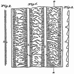
[Drawings of reissued patent No. 3,001, granted June 23, 1868, to G. E. King, published from the records of the United States patent office.]
has such conformation given to it without having recourse to laundering or washing.
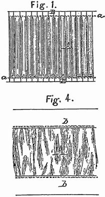
A patent had been granted to the plaintiff on the 23d of October, 1866 [No. 59,036], for an “improvement in fluted puffing for shirt bosoms,” in which he claimed, as an article of manufacture, what he called a “fluted puffing,” made by fluting, by mechanism, and in a regular manner, a strip of muslin, or other material, throughout its length, and compressing and flattening down the extremities of the flutes, to form straight and regular borders on either and opposite sides of the flutes, and afterwards machine stitching said borders along and at the union of the borders with the flutes. It is manifest that this article, for the space between the flattened portions, consists, as made, and before being washed or laundered, wholly of flutes; that, in order to convert such fluted portion into a crinkled, gathered or irregularly waved portion, it is necessary to launder or wash it; and that such conversion can be made by laundering or washing it.
Figure 1 of the drawing represents a face view of the puffing “previously to its being washed,” and represents it as wholly in flutes between the flattened portions. Figure 4 of the drawing represents a face view of the puffing “after having been washed, and as sewed between the plaits of a shirt bosom,” and represents all the part that is in view, 560which is the part between the flattened portions, as being crinkled, gathered or irregularly waved. In view of this patent of 1866, the reference, in the specification of reissue No. 3,001, to the formation of the crinkled portion of the puffing, without recourse to washing or laundering, becomes intelligible.
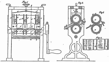
The specification of No. 3,000 says: “This invention is designed for making puffing applicable to shirt bosoms, trimming, or other purposes of dress, in which the article, as it issues from the machine, is (without having recourse to laundering) delivered in a complete form, either singly or in two or more series or rows, composed of flattened borders, with flutes running along their inner edges, and puffed or crinkled surfaces between the flutes. The invention consists in a guide constructed with one or more curved or arched portions, in combination with one or more suitable fluting rollers, whereby the material, in passing through the machine, is fluted, and contracted laterally, as it were, or drawn up, between the flutes, to produce the required crinkled surface or surfaces in the puffing.” Two fluting rollers, one above the other, are placed in a frame, with their ends projecting through large vertical slots formed in the ends of the frame. The lower roller is supported in semi-circular bearings formed in the lower ends of the slots, and is furnished at one end with a crank. The upper roller works in semi-circular bearings formed in sliding blocks placed upon the ends thereof, and pressed down upon the same by a spring, the tension of which may be regulated by means of a vortical screw situated centrally in the top of the frame. When desired, the upper roller may be held within a given distance of the lower roller by vertical set screws, situated one at each end of the top of the frame, and acting upon the sliding or adjustable bearings. The puffing is represented in one of the figures of the drawing, and is formed of strips of any suitable fabric, and of a width, when finished, nearly, or quite, equal to the length of the fluting rollers, and is formed with longitudinal portions, which are fluted transversely to the length of the strip; also, with portions outside of the fluted portions, in which the fabric is pressed flat, and through which longitudinal rows of stitching are formed, to render permanent the conformation of the puffing; and, also, with portions between the fluted portions, which are intended to be wider than the parts just described, and which are puffed or crinkled in such manner as to possess an irregular wavy surface. In order to form these several portions of the puffing, each of the fluting rollers is formed with as many annular or circumferential series of grooves and flutes as there are fluted portions upon the puffing, with as many plain, narrow annular faces as there are flattened portions, and with as many plain and comparatively broad portions as there are puffed portions in the finished puffing, each of the said parts of the rollers being of the same width as that portion of the completed puffing which it is designed to shape, and the plain and comparatively broad circumferential faces or portions being of such diameter that, when the two rollers are in proper position, those upon one roller will be situated at such distance from those upon the other, that no considerable pressure will be
[Drawings of patent No. 59,036, granted October 23, 1866, to G. E. King, published from the records of the United States patent office.]
exerted upon the fabric in passing between them, and the several series of grooves and flutes upon one roller gearing into those upon the other roller. There are pressers, the rearmost end of each one of which is curved downward, and fitted upon the upper rearmost part of each of the plain, narrow annular faces of the lower roller, while its forward end is curved upward in contact with the forward sides of the corresponding plain, narrow annular face upon the upper roller, the rearmost ends of the pressers being pressed against the lower roller by set-screws passing through a horizontal bar or brace secured upon the rear of the frame. Fixed upon the forward side of the frame, in front of the lower roller is a horizontal supporting brace, which has fixed upon it an inclined plate, upon which is supported an inclined guide, E, which is composed of two pieces of sheet metal, secured one over the other, at such a distance apart as to permit the passage of the cloth or fabric between them, and those parts of the guide in front of the plain and comparatively broad cylindrical portions of the rollers are curved up or arched transversely, as shown at a′, in such manner that the width of the fabric passed between each pair of such plain and comparatively broad portions will be greater, if stretched out to its full extent, than the width of said portions, so That the fabric, by means of its increased width, will be crinkled or puffed in passing between said portions. The end of the strip of fabric from which the fluted puffing is to be formed, is passed into and through the guide, and between the rollers, and a rotary motion is communicated to the rollers. The fabric is drawn lengthwise between the rollers, those portions thereof which pass between the several opposite series of grooves and flutes in the two rollers being fluted, while those portions thereof which pass between the smooth, annular faces of the rollers, being formed into gathers by the fluting of the fabric at the sides or edges thereof, are pressed flat by passing under the pressers, as the fabric is drawn along, at the same time that those portions of the fabric drawn through the curved or arched parts of the guide, being, if stretched to their full extent, of a width greater than that of the smooth and comparatively broad cylindrical portions, and being also gathered by the fluting formed at their sides or edges, are caused to assume a crinkled or puffed form, as they are passed between the said smooth and comparatively broad portions, the distance between such opposite portions being such that no pressure is 561exerted upon the fabric passing between them, beyond that required to simply press the convex surfaces thereof downward to a sufficient degree to insure the shaping thereof into the puffed condition just described. The extent to which the material will be thus contracted laterally, as it were, or drawn up, between the flutes, will be governed by the excess in length of the arched portions of the guide over a straight line or lines connecting such arched portions at their base. By these means the fluted puffing is brought into the form required in the finished article, without the necessity of washing the same in order to bring the puffing into such form. To complete the puffing, longitudinal rows of stitching are formed in the flat parts of the puffing, to retain it in shape. The foregoing description is found in the specification. The claim is in these words: “The guide E, constructed with one or more curved or arched portions, a′, in combination with suitable fluting rollers, substantially as herein set forth, for the purpose specified.”
[Drawings of reissued patent No. 3,000, granted June 23, 1868, to G. E. King, published from the records of the United States patent office.]
In view of the prior existence of the puffing called the Pipo puffing, it is impossible to sustain reissue No. 3,001. The puffing claimed in that reissue is claimed as a new article of manufacture, without reference to whether it be made by machinery, or by hand, or how otherwise. Any prior article, which had, as its characteristic features, as an article of manufacture, the features set forth in that reissue, as the characteristic features of the puffing claimed therein, is an anticipation of the patent. The Pipo puffing was made on a sewing machine, but it was formed complete without laundering or washing, and it consisted of flattened borders, with flutes running along their inner edges, and a puffed, or gathered or crinkled surface between the flutes, and longitudinal rows of stitching were passed through the flattened borders, to render permanent the conformation. The flutes were formed by the process of gathering, and were not as regular and uniform, each flute with every other flute, as where flutes are made by fluting rollers. But this is a question of degree, and of appearance, and not of conformation.
The claim of reissue No. 3,001 speaks of forming the puffing by crinkling one portion of the strip “simultaneously” with fluting it along the edges of such portion, and forming flattened borders outside of the flutes. If the word “simultaneously” be construed as referring to the idea that, in any given cross section of the strip, the crinkled portion, the fluted portions and the flattened borders are formed at one and the same time, then an element is introduced which has regard to something beyond the conformation of the puffing as an article of manufacture, and its shape and structure when completed—an element which has to do with the process of making it. The specification, in its descriptive part, in no manner makes any part of the invention to consist in any part of any process of making the puffing, or of any machinery or apparatus for making it, nor does it suggest that the parts embraced in any cross section are to be made simultaneously with each other, or that any peculiarity in conformation would result from so doing. Therefore, such a construction of the word “simultaneously” would make the claim repugnant to the subject matter of the patent. The only proper construction, then, of the word is, that it merely means, that, in the finished article, one portion is seen to be crinkled, and, at the 562same time, the parts at the edges of such portion are seen to be fluted, and the portions outside of the flutes are seen to be flattened borders.
We come now to the consideration of the machine used by the defendant, and alleged to infringe reissue No. 3,000, in making the puffing which is alleged to infringe reissue No. 3,001. The defendant's machine is described in letters patent granted to him January 7th, 1873, for an “improvement in crimping and fluting machines.” He uses, in connection with fluting rollers, as the specification of his patent states, “a detent or finger, by which a portion of the fabric is held back, and thereby formed into Y-shaped, but more or less irregular, lateral waves and crinkles.” Between the fluted portions of the fluting rollers are plain zones. The free end of the detent bears against a platform midway of the plain zones. The fabric, in its passage to the rollers, passes over the platform and under the detent, which is a spring, and which so presses the fabric against the platform, while the rollers are drawing the fabric forward, as to detain or hold back that portion of the fabric which is so pressed by the detent, and cause it to be crinkled in the space between the inner edges of the flutes. This result is attained because the same thing is done as in the plaintiff's machine, that is, the width of the fabric passed between the pair of plain zones is greater than the width of such zones, and as the fluting gathers the fabric, the portion of it which passes between the pair of plain zones is crinkled. The defendant's machine has pressers which make flattened borders along the outer edges of the fluted portions, through which stitching may be made.
The main feature of the plaintiff's machine is the device for pulling away the fabric before the fluting rollers grasp it too firmly, so as to get the increased width of fabric opposite the pair of plain zones. The plaintiff shows how this is to be done by an arched guide. This arch raises up the fabric. The fabric rides over it, and so is pulled away from the fluted parts of the rollers. The obstacle interposed by the arched guide pushes up the fabric to an apex. There would be no difference in mode of operation, if the fabric were pushed down to a given point by an arched guide. The defendant interposes an obstacle which pulls back the fabric from the fluted parts of the rollers. The mode of operation is the same as in the plaintiff's machine, and the result is the same. The only difference is, that, in one, the centre of the extra width moves upward as the pull is made, and, in the other, it does not; but, in each, the detaining instrument diverts the fabric from what would otherwise be its course, so as thereby to pull out the extra width. I think the variation is merely mechanical and not substantial, and that the defendant's machine is an infringement. The detent and the platform form the two surfaces of a guide between which the fabric passes, and these surfaces hold it so as to pull it away from the flutes. The two surfaces of the plaintiff's guide do the same thing.
Reissue No. 3,000 is not successfully attacked as to the novelty of its claim.
As to the Robjohn patent, and Robjohn machine, and Robjohn guides 1 and 2, the machine was designed to make two double fold ruffles at one and the same time. It has no provision for taking up an increased width of material, or for crinkling a central portion of the material. Nor could such guides, or the guides S and T, produce, in connection with the Robjohn machine, the results produced by the mechanism covered by the claim of reissue No. 3,000. The flat Muller guide No. 5 falls within the same category. The Muller guide No. 5, with the arched projection, has not two surfaces between which the material passes; and, used, as it always was, with the Muller rings Nos. 3 and 4, which were diamond embossing rings, and made a diamond figure on the material, and occupied all the space not occupied by the fluting rollers, it does not present the combination set forth in the claim of reissue No. 3,000, for the purpose specified in that reissue.
The Weitling machine and apparatus, whether as originally presented to the patent office, or as existing and used before King's invention, did not contain the combination of the claim of reissue No. 3,000. Moreover, such use as was made of it before King's invention was wholly experimental, and it was abandoned by its inventor, as an abortive experiment.
There must be a decree for the plaintiff as to reissue No. 3,000, for an account of profits and damages, with an injunction, with costs.
In the two suits brought against vendors of puffing, on reissue No. 3,001, the bills must be dismissed, with costs.
[NOTE. An appeal was then taken by Werner to the supreme court, where the decree was reversed in an opinion by Mr. Justice Miller, who said that there was not only a great difference in the shape or form of the guide of these two machines, but they operated on entirely different principles. In King's machine the redundant fullness which makes the puff is produced by a pressure which is uniform over the surface of the fabric, the two plates giving it the exact form required, and no other; while Werner's finger seizes the fabric in the centre of the part to be crinkled, and by pulling on it at this central point, as it is dragged in between the rollers, enough of the material is drawn in from the edges towards the center to create the redundancy necessary to the puff or crinkle. 96 U. S. 218.
[For other cases involving this patent, see note to King v. Maudelbaum, Case No. 7,799.]
1 [Reported by Hon. Samuel Blatchford, District Judge, reprinted in 1 Ban. & A. 386; and here republished by permission.]
2 [Reversed in 96 U. S. 218.]
This volume of American Law was transcribed for use on the Internet
through a contribution from Google. 