Case No. 5,954.
HALL v. WILES.
[2 Blatchf. 194;1 1 Fish. Pat. Rep. 433.]
Circuit Court, S. D. New York.
April 17, 1851.
PATENTS—INFRINGEMENT—DISCLAIMER—WHEN COSTS NOT ALLOWED UPON DISCLAIMER—PATENTABILITY WHERE COMBINATION IS PART NEW AND PART OLD—PROVINCE OF JURY ON QUESTIONS OF PATENTABILITY—MEASURE OF DAMAGES.
1. Where a patent contains several claims, and the invention covered by one of them is not new, the patentee may, under the 7th and 9th sections of the act of March 3, 1837 (5 Stat. 193, 194), maintain an action for the infringement of the patent, so far as regards the valid claims, although he did not, before the commencement of the action, make or record a disclaimer of so much of the thing patented as he claimed without right; but he will not be entitled to costs.
[Cited in Cahart v. Austin, Case No. 2,283: Tuck v. Bramhill, Id. 14,213; Smith v. Nichols, 21 Wall. (88 U. S.) 117; Burdelt v. Estey, Case No. 2,145; Sessions v. Romadka, 145 U. S. 41, 12 Sup. Ct. 802.]
2. Under the 9th section of the act, the question whether there has been unreasonable negligence or delay on the part of the patentee in entering such disclaimer, is a question which goes to his right of action.
[Cited in Dunbar v. Myers, 94 U. S. 194.]
3. A disclaimer is necessary only where the thing claimed without right is a material and substantial part of the thing patented.
[Cited in Peek v. Frame, Case No. 10,904; Worden v. Searls, 21 Fed. 408.]
4. Where the thing claimed without right is a part of the machine, if it is not an essential part, and was not introduced into the patent through the wilful default of the patentee, or with intent to defraud or mislead the public, the want of a disclaimer in regard to it affords no ground for invalidating the patent.
[Cited in Stimpson v. Woodman, 10 Wall. (77 U. S.) 125; Electrical Accumulator Co. v. Julien Electric Co., 38 Fed. 136.]
5. Where one part of a combination is new the combination is a new one, though the other parts of the combination may be old.
6. A formal change, such as a change of proportions, a mere change of form, or a different shape, is not, within the meaning of the patent law, a change sufficient to support a patent; but the improvement upon the old contrivance must embody some originality, and something substantial in the change, producing a more useful effefct and operation.
7. In determining the question of patentability, the jury have a right to take into consideration, in connection with the change, the result 281which has been produced; because the result, if greatly more beneficial than it was with the old contrivance, reflects back, and tends to characterize in some degree the importance of the change.
8. In this case it was held, that the thing patented, namely, a carriage in a brick-press, was not a combination of materials, within the doctrine of the patent law, and that the principle, that unless the defendant had taken the whole of the combination he was not liable, did not apply.
[Cited in Mabie v. Haskell, Case No. 8,653.]
9. The rule of law as to damages, when an infringement is made out, is, to give to the plaintiff the actual loss he has sustained, and nothing more. Exemplary or vindictive damages cannot be given.
[Cited in Perry v. Corning, Case No. 11,003.]
10. In this case it was held, that the plaintiff was entitled, if his case was made out, to the profits on all the machines sold by the defendant.
[Drawings of patent No. 2,768, published from the records of the United States patent office.]
This was an action on the case [by Alfred Hall against John Wiles] tried before Nelson, Circuit Justice, for the infringement of letters patent [No. 2,708], granted to the plaintiff on the 3d of September, 1842, for an “improvement in the construction of the brickpress.”2 The points raised on the trial are stated in the charge of the court.
282Francis B. Cutting, for plaintiff.
Setl P. Staples and Ambrose L. Jordan, for defendant.
NELSON, Circuit Justice, (charging the jury). The patentee's description of his invention sets it forth with great particularity and clearness, and models have been produced which render it perfectly intelligible. After describing the various parts of this machine, the patentee closes, as is usual, with a specification of the particular things which he claims to have invented.
The first is, the segment slides, acted on by springs, in combination with the platen and hopper, constructed and arranged as described in the specification. The object of this contrivance is, to close the slot in the end of the press which was before open, and through which the shaft of the press moves, in order to prevent the mortar from being pressed out of the aperture. The patentee nest claims the combination of the carriage E, suspended at its rear end in the frame, with the connecting-rods and shaft for freeing the machine from obstructions. He claims, also, the construction of the carriage E, so as to free itself from dirt—meaning all the parts used by him, in the construction of this carriage, to effect the purpose intended—that is, to free it from dirt, which seems to have been a difficult thing in these machines; and he claims, also, the carviage E, thus arranged, in combination with the movable carriage F, constructed in the mode pointed out in the specification. These are the things he claims, each of which he supposes to be an improvement on all prior machines in use.
As to the first claim, the defendant insists that, whether original or not, the contrivance is destitute of utility, and could not be carried into practical effect, and was abandoned by the patentee immediately. The defendant's counsel assume the fact to be proved, and then insist that, as this claim is invalid, either from want of originality or utility, the whole patent becomes void., This is a question of law for the court to decide. It is argued by the defendant that, in order to have saved the patent, the patentee should have disclaimed this part of his patent, under the 7th and 9th sections of the act of March 3, 1837 (5 Stat 193, 194) and that, as he has failed to make this disclaimer and to record it, this suit cannot be maintained and the whole patent is void. Though there is some evidence going to 283show that this contrivance may be new, and may not have been used before, yet, perhaps, the weight of it is that it is useless or could not be operated. I have examined the provisions of the statute, and am of opinion that this suit may be maintained, under the two sections referred to, notwithstanding a disclaimer of the first claim has not been made or recorded; but the plaintiff will not be entitled to costs. The provision in the 9th, section, that no costs shall be recovered, unless a disclaimer of all that part of the thing patented which is claimed without right, is entered before the commencement of the suit, certainly shows that the action may be maintained for other parts of what Is patented. If the disclaimer was entered in the patent office before the suit was instituted, the plaintiff recovers costs in the usual way, independently of any question of disclaimer. But if, in the progress of the trial, if turns out that a disclaimer ought to have been made as to part of what is claimed, the plaintiff may recover, but will not be entitled to costs.
Another question arises under the 9th section—whether there has been unreasonable negligence or delay in entering a disclaimer. That is a question which goes to the right of action. If the delay shows great negligence, the jury may say that the patent is void. The provision in question applies only in the case where the part claimed by the patentee, of which he is not the Inventor, is a material and substantial part of the thing patented. A disclaimer is necessary, therefore, only where the thing claimed without right is a material and substantial part of the machine invented. The question as to the disclaimer in this case is, therefore, of no importance in the determination of the rights of the parties, unless the slides and springs claimed in the first claim are described as a material and essential part of the machine, or unless they were introduced into the description through the wilful default of the plaintiff, or with intent to defraud or mislead the public. If you find that these slides and springs are not essential to the machine, and were not introduced into the patent through such wilful default or intent to defraud or mislead the public, the want of a disclaimer in regard to them affords no ground for invalidating the patent.
As to the second claim. If the carriage E, which is one part of the combination as arranged by the patentee, is a new and useful improvement, the combination of that with the connecting-rods and shaft, for letting it down and freeing it from obstructions, will be maintained, though the latter may be old. Because, one part of the combination being new, the uniting that with an old contrivance makes the combination necessarily a new one.
I pass now to the third claim, and to the real point in controversy. The arrangement of the carriages E and F is a distinct and independent claim—a material and substantial one—and one without which the substratum of the invention would fail. This brings the case very much to the point, whether the carriage E, constructed as it is described in the specification, is of itself a new improvement, in view of the carriages which had been in use prior to the invention of the plaintiff. It is necessary that it should be new, in order to uphold the third claim; and that, if maintained, will uphold the second. The question is one of fact. A great deal of evidence has been given on both sides, all bearing on the point; and, except that there are some legal principles bearing on the question of fact, and as to which the court may aid you, it is a question which must be determined by the good sense and sound judgment of the jury. Of course, the question is not, whether the plaintiff's was the first bed or carriage that had ever been used; because, it is admitted that carriages and beds had before been used. But the question is, whether the plaintiff's carriage, as constructed by him is a substantial improvement, for the purpose for which it is used, on all previous carriages. A formal change, such as a change in proportions, a mere change of form, or a different shape, is not a change within the meaning of the law. An improvement upon an old contrivance, in order to be of sufficient importance to be the subject of a patent, must embody some originality, and something substantial in the change producing a more useful effect and operation. And, in determining this question, the jury have a right to take into consideration, in connection with the change, the result which has been produced. Because, the result, if greatly more beneficial than it was with the old contrivance, reflects back, and tends to characterize, in some degree, the importance of the change.
I do not agree with the counsel for the defendant, that the carriage E, as constructed by the patentee, is to be regarded as embracing a combination of materials, within the doctrine of the patent law, and that, unless the defendant has taken the whole of the combination, he is not liable. My opinion is, that that principle does not apply.
If the carriage E, as constructed by the plaintiff, is not a substantial improvement upon all previous constructions, he is not entitled to recover. But, if you arrive at the conclusion that that carriage is a substantial improvement upon all previous constructions, then the question is, whether the carriage used by the defendant is identical with that of the plaintiff. If it is, it is an infringement, and the plaintiff is entitled to recover.
The rule of law as to damages, when an infringement is made out, is, to give to the plaintiff the actual loss which he has sustained, and nothing more. Exemplary or 284vindictive damages cannot lie given. If the damages are insufficient, there is a provision of law authorizing the court to treble them. The plaintiff is entitled, if his case is made out, to the profits on all the machines sold by the defendant.
The jury found a verdict for the plaintiff for $1,000 damages.3
1 [Reported by Samuel Blatchford, Esq., and here reprinted by permission.]
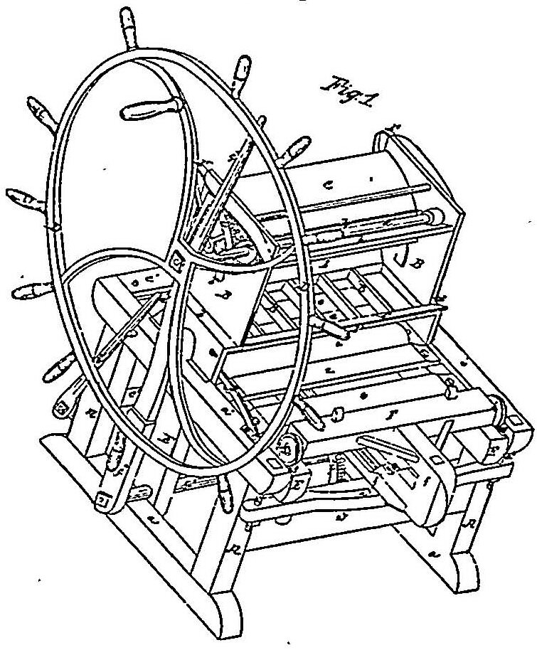
2 The specification was as follows: “Be it known, that I, Alfred Hall, of Cleveland, in the county of Cuyahoga, and state of Ohio, have invented a new and useful improvement in the machine for moulding bricks, and I do hereby declare, that the following is a full, clear and exact description thereof, reference being had to the accompanying drawing, making a part of this specification, in which Pig. 1 is an isometrical projection, Pig. 2 is a longitudinal vertical section. The nature of my invention consists in constructing a moulding machine, to be attached to a common tempering tub, with revolving knives, of the usual construction, from which the mortar is conducted directly into the moulds, into which it is forced by the press. To this machine, an apparatus is affixed for removing the moulds, and, when obstructed by stones, &c., to relieve them therefrom. The frame of the machine consists of four upright posts, (A,) framed into two sills, (a) and cappieces, (a 1,) which are connected by crossties, (a 2,) forming a stout frame of proper proportions for containing the machinery. To each of the caps (a 1) are attached metallic plates (B.) on the inside near the centre of the frame. Prom the lower part of these plates flanges project, which embrace the caps and serve to steady them: these plates have shoulders at (b,) turning inward, from which to the top they are vertical. They are wide enough to form the sides of the hopper, and contain the pressing apparatus hereafter described. A grating, (B 1,) which forms the bottom of the hopper, is attached to the plates (B) at the shoulder, (b,) just high enough to clear the moulds. The bars of this grating correspond with the partitions in the moulds, and must be varied for every different kind ot brick: they are chamfered off on their upper edges, and serve to direct the clay into the mould; the back piece of this grating rises at (b 1,) (see Pig. 2,) to the press platen, to prevent the escape of the mortar; there is also a similar projection (b 2) at the front of the grate, having on its upper edge an apron, (b 3,) which rests in the spout of the tempering machine, (shown in dotted lines,) and directs the mortar into the machine. The platen (C) is the segment of a cylinder, its lower surface being fitted to the grate and projection, (b 1;) it does not extend quite out to the plates, (B,) but has a projecting flange (c) at each end, around the periphery, and down the under side, made of metal, which shuts out the mortar from the end of the cylinder segment; on each end of this laten an iron cross-brace is let in, (lettered c;) its inner end has a hole through it on which the platen turns on its shaft or fulcrum, (c 3;) from these braces, near the periphery of the platen, studs (c 4) project, which extend out through the plates, (B,) slots (b 4) being cut in them for the studs to play in; these slots are covered when the platen is thrown back, by brass segment slides, (c 5,) which are pushed forward from the platen by means of springs, (c 6,) which bear against studs projecting from the side of the slides let into its ends; when the platen is forced down, these segments strike the grate and are stopped, the spring yielding for that purpose. The platen thus constructed turns on its shaft, (c 3,) which has its bearings in the plates (B) by means of a segment rack (c 7) outside the plates on each side, with which it is connected by the shaft and studs above named; the teeth on these racks mash into pinions (d) on a shaft, (d 1,) which has its bearings in tie plates over the platen; on one end of the shaft (d 1) there is a large hand-wheel, (D,) by which the platen is put in motion; between the caps (a 1) of the frame above mentioned, a carriage (E) is placed; it is formed of two side frames, of a T shape, firmly braced, the horizontal part extending out about the length of the caps, and the vertical nearly down to the bottom of the frame; these T flames are connected by a brace (not shown in the drawing) running from one to the other. Just under the grating, three horizontal rollers (e) are placed, having their journals turn in bearings on the upper side of the T frames of the carriage; to these frames, on each side of the roller, slots (e 1) are affixed in the upper side; on these the moulds slide; this carriage is sustained in the frame at the rear end, on a cross-piece (a 3) which is suspended to the end of the cap (a 1) that projects over the post (A) by a rod (a 4) at each end, which can be drawn up by a screw below the cross-piece; the carriage is steadied by a pivot (e 2) projecting from each side, near the end that turns in the posts of the frame, and at the other end by studs, (e 3;) these are necessary, as the carriage is made smaller than the space between the sides of the frame, so as to give a free passage to any dirt that may collect on the machine, which would tend to clog its operation, (see section 1.) At the front end of the carriage are jointed stout connecting rods, (e 4,) which extend down to a revolving shaft (e o) which turns in bearings, (e 6,) attached to the front posts of the frame, and which are also connected to the cap by rods (e 7) running from the cap to the bearings, (e 6;) on the upper side of this shaft are short projections, to which the connecting rods are coupled, and by which this end of the carriage is supported; on the end of the shaft (e 5) a lever (e S) is put, which extends up and rests against a pin in the frame near the lever. It will readily be seen, that by bringing the lever forward, the end of the carriage resting on the shaft will be lowered down; on each side of the carriage an iron rail (e 9) is affixed, extending from the rear end to the rollers; this rail rises a little above the side-pieces, which are cut out on their upper edge, away from it, except at the points of attachment, so as to allow any dirt that may get upon the rail to fall through without clogging the machine; a wheel (f) runs on each side of these rails, which are connected by an axle or movable carriage, (F,) formed of a square straight piece of wood; a piston (f 1) is attached to the back of this carriage, which curves down and runs forward horizontally under the centre of the machine, just below the cross-piece connecting the sides of the carriage, against which, or a friction roller which may be attached thereto, it bears when in motion; on the under side of this piston a rack is formed, which meshes into a segment rack (f 2) on a shaft, which has its bearings in the lower end of the vertical pieces of the carriage above named; to the end of the shaft (f 3) a lever (f 4) is affixed, which rises up beside the shaft, (d 1,) so as to be convenient to work by the operator; the moulds, (G,) which are like those now in use in other machines, are put into the machine opposite that on which the wheel (D) is; they are prevented from being pushed too far through by a spring (g,) which guides them in entering the machine; they are forced under the grating by the movable carriage, (F,) acted on by the lever, (f 4;) when this machine is attached to a “tempering machine,” it receives the mortar directly from it into the grating, and into the moulds underneath it; the hand-wheel' is then turned, which brings down the platen and forces the mortar into :he moulds; the lever (f 4) is then brought forward, and the empty mould which is placed forward in the grating between the full mould and the movable carriage, and forced under the grating, the full mould being driven out on the opposite side, the weight of the mortar in the tempering machine, at the same time, raises the platen by its pressure upon it till the segment (c 7) strike against the springs, (b 5.) which prevent the platen from receding too far. If, when the full mould is being forced out, a stone or other obstruction stops its motion, the lever (f 4) is drawn forward, and the carriage on which the mould rests is lowered till the difficulty is overcome, when it is again raised to its place; over the platen, and between it and the shaft, (d 1,) a brace (h) runs across from one side platen to the other, on the under side of which a scraper (h 2) is affixed, that fits close to the circular side of the platen, and serves to free it from the mortar that adheres to it when run down; just over the scraper a board (h 1) is placed, the lower edge of which rests on the scraper, its upper edge projecting up towards the “tempering machine,” at an angle of about 45°; this forms the upper part of the hopper, and confines the mortar while the press acts. What I claim as my invention, and desire to secure by letters patent, are the segment slides (c 5) acted on by springs, in combination with the platen and hopper, constructed and arranged as herein set forth. I further claim the combination of the carriage (E) suspended at its rear end with the connectrods (e 4) and shaft, (e 5,) for freeing the machine from obstructions, substantially as before specified. Lastly, I claim the construction of the carriage (E) so as to free itself from dirt, that is to say, the pivots and studs for steadying the carriage, the slatted top and railway, set off from the carriage, &c., and, in combination therewith, the movable carriage (F) constructed and operated as herein described.”
3 A motion for a new trial in this case was subsequently made before Judges Nelson and Betts, no the ground of alleged errors in the charge, but it was denied.
This volume of American Law was transcribed for use on the Internet
through a contribution from Google. 