Case No. 5,402.
GIBSON v. VAN DKESAR et al.
[1 Blatchf. 532;1 1 Fish. Pat. Rep. 369.]
Circuit Court, N. D. New York.
June Term, 1850.
PATENTS—ANALOGOUS DEVICES—COLORABLE IMITATIONS—INFRINGEMENT—VALIDITY—PROVISIONAL INJUNCTION.
1. Rotary guides, so arranged and adjusted as to press, by means of weights, against the edges of the board, while it is undergoing the operation of the plane or cutter, and placed obliquely to the motion of the board, so as to produce, as they revolve against the edges, a constant tendency to keep the board to its bed, are a mere analogous device, when substituted for pressure rollers in the combination for planing covered by Woodworth's patent. The difference between the rotary guides and the pressure rollers is one of form, not of substance.
2. The case of Gibson v. Harris [Case No. 5,396], cited and applied.
3. A revolving cutter-wheel, having bevels or offsets around its face, as patented to John Levy, assignee of Hazard Knowles, April 10th, 1849, is a colorable imitation of the rotary cutters of Woodworth.
4. Such cutters were involved in the cases of Woodworth v. Wilson, 4 How. [45 U. S.] 712, and of Van Hook v. Pendleton [Case No. 16,851].
5. A. planing machine containing a combination of such rotary guides with such cutters is a infringement of Woodworth's patent.
6. The validity of Woodworth's patent being fully settled, and the court being entirely satisfied that the defendants' machine was substantially identical with Woodworth's, a provisional injunction was granted.
[Cited in Green v. French, Case No. 5,757; McWilliams Manufg Co. v. Blundell, 11 Fed. 422.]
2[Motion for provisional injunction.
[Suit brought [by John Gibson against Stephen Van Dresar and Daniel Stearns], on letters patent for an improvement, in the method of planing, tonguing, and grooving, and cutting into moldings, or either, plank, boards, or other material, and for reducing the same to an equal width and thickness, etc., granted to William Woodworth, December 27, 1828, extended in the name of his administrator, William W. Woodworth, for seven years from December 27, 1842, reissued July 8, 1845, and again extended by act of congress for seven years from December 27, 1849.
[The plaintiff, who was assignee of said reissue under the second extension, claimed that a machine which the defendants were operating in Oneida county, state of New York, was an infringement of the Woodworth patent. Those parts of the specification and the claims of said reissue which are material to the present case are as follows:
When the planks or boards have been thus prepared (on separate machine), they may be placed on or against a suitable carriage, resting on a frame or platform, so, as to be acted upon by a rotary cutting or planing and reducing wheel, which wheel may be made to revolve either horizontally or vertically, as may be preferred. The carriage which sustains the plank or board to be operated upon may be moved forward by means of a rack and pinion, by an endless chain or band, by geared friction rollers, or by any of the devices well known to machinists for advancing a carriage or materials to be acted upon in machines for various purposes. The plank or board is to be moved on toward the cutting edges of the cutters or knives, on the planing cylinder, so that its knives or cutters, as they revolve, may meet and cut the plank or board in a direction contrary to that in which it is made to advance.
3302 [William Woodworth.
[Planing Machine,3 Patented Dec. 27, 1828. Extended Dec. 27, 1843; and Dec. 27, 1849. Reissued July 8, 1845.
[Wm. Woodworth.
[Planing Machine Patented Dec. 27, 1828. Extended Dec 27, 1842, and 1849. Reissued July 8, 1845.
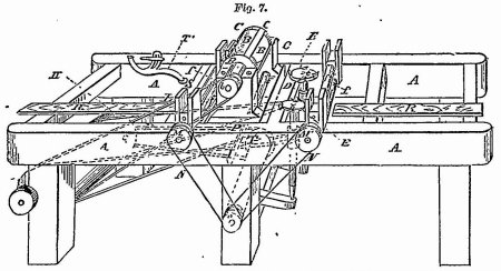
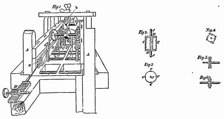
In the accompanying drawing, figure 1 is a perspective representation of the principal operating parts of the machine, when arranged and combined for planing, tonguing, and grooving, and when so arranged as to be capable of planing two planks at the same time, the axis of the planing wheel being placed vertically. A A is a stout, substantial frame of the machine, which may be of wood or of iron, and may be varied in length, size, and strength, according to the work to be done. B B are the heads of the planing cylinder, and C C, the knives or cutters, which extend from one to the other of said heads, to the peripheries of which they may be attached by means of screws. The knives, C C, with the faces forming a planing angle, may be placed in a line with the axis, J, of the cylinder, or they may stand obliquely thereto, as may be preferred; but in the latter case the edge should form the segment or portion of a helix, b represents a pulley near to the upper end of the axis, J, and J. a pulley or drum, which may be made to revolve by horse, steam, or other motive power, and from which a belt may extend around the pulley b, to drive the planing cylinder and other parts of the machinery. G is the carriage which is represented as being driven forward by means of a rack and pinion, H. Against this carriage, the plank K, which is to be planed, tongued, and grooved, is placed, and is made to advance with it It will be manifest however, that the plank may be moved forward by other means, as, for example, by an endless chain or band, passing around drums or chain wheels, or by means of geared friction wheels, borne up against it To cause the carriage and plank to move forward readily, there may be friction rollers, f f f, placed horizontally, and extending under them. The rollers, f f f, which stand vertically, are to be made to press against the plank and keep it close to the carriage, and thus prevent the action of the cutters from drawing the plank up from its bed in cutting from the planed surface upward. They may be borne against it by means of weights or springs, in a manner well known to machinists. In the single horizontal machine, the horizontal friction-rollers may be geared, and the pressure-rollers placed above them to feed the board with or without the carriages, a bed-plate being used directly under the planing cylinder. Figure 7 represents the same machine, with the axis of the planing-cylinder placed horizontally, and intended to operate on one plank only at the same time. A A is the frame; B B the heads of the planing cylinder; C O the knives or cutters attached to said heads. To meet the different thicknesses of the planks or boards, the bearings of the shaft or cylinder may be made movable, by screws or other means, to adjust it to the work; or the carriage or bed-plate may be made so as to raise the board or plank up to the planing cylinder. E and E are the revolving cutters, or tonguing and grooving wheels, which are placed upon vertical shafts, having upon them pulleys, D D, around which pass belts or bands from the main drum, I, to which a revolving motion may be given by any adequate motive power.
From the drum, I, a belt L, passes also around the pulley, b, on the shaft of the planing-cylinder, and gives to it the requisite motion. There may in this machine be a horizontal carnage, moved forward by a rack and pinion, in a manner analogous to that represented in figure 1; but in the present instance the plank is supposed to be advanced by means of one or two pairs of friction or feed-rollers, shown at f f. The uppermost, f f, of the pairs of rollers, may be held down by springs, or weighted levers, which it has not been thought necessary to show in this drawing, as such are in common use. The lowermost of these rollers may be fluted or made rough on their surfaces, so as to cause friction on the under side of the plank. R R are guide-strips, used In place of the rollers used for the same purpose, and also for bearing or friction-rollers, when the machine is vertical, to direct one edge of the plank, and against its opposite edge. Any pressure may be used equal to the weight of the board or plank, when worked in a vertical position. One of the cutter-wheels should be made adjustable, to adapt it to stuff of different widths.
The planing cylinder, and likewise the cutter or tonguing and grooving wheels, may be constructed in the manner represented in figures 2, 3, 4, 5, and 6, and hereinbefore fully described. One of the heads of the planing-wheel may be made movable, to accommodate its width to the width of the boards or plank to be planed.
What is claimed therein as the invention of William Woodworth, deceased, is the employment of rotating planes, substantially such as herein described, in combination with rollers, or any analogous device, to prevent the boards from being drawn up by the planes when cutting upward, or from the induced or planed to the unplaned surface, as described.
And also the combination of the rotating-planes, with the cutter wheels for tonguing and grooving, for the purpose of planing, tonguing, and grooving boards, etc., at one operation, as described. And also the combination of the tonguing and grooving cutter-wheels for tonguing and grooving boards, and at one operation, as described. And finally, the combination of either the tonguinff and grooving cutter-wheel, for tonguing and grooving boards, etc., with the pressure-rollers, as described, the effect of the pressure-roller in these operations being such as to keep the boards, etc., steady, and prevent the cutters from drawing the boards toward the center of the cutter-wheels whilst it is moved through by machinery
332[H. Knowles.
[Planing Machine. Patented Apr. 10, 1849.
In the planing operation, the tendency of the plane is to lift the boards directly up against the rollers; but in the tonguing and grooving, the tendency is to overcome the friction occasioned by the pressure of the rollers.
4[The defendants resisted the motion, principally on the ground that the machine used by them was substantially different in construction and operation from that of Woodworth, and, therefore, no infringement. Their machine was constructed in accordance with letters patent for au Improvement in planing machine granted to John Levy, assignee of Hazard Knowles, April 10, 1849. They held under Levy. Those parts of the specification and claims of the Levy patent, involved in the present controversy, were as follows:
[“My second improvement is more particularly applicable to the cutter-wheel of Bramah. That improvement consists in forming one, two or more offsets, or in lieu thereof one or more bevels, near the outer periphery of the cutter-wheel. Upon the circuit of the outer or deeper of these offsets is set a series of reducing cutters, marked h, h, fig. 5. These cutters may project a short distance beyond the periphery of the wheel A. The purpose of the offsets or bevels is, to allow a board thicker than the finished work is intended to be, to enter between the edge of the Wheel and the face of the bench or support. The side or projecting corner of the reducing cutter is made sharp, as well as the lower edge, as represented at h, h, fig. 5. Entirely within the outer circumference of the wheel are set, through inclined mortices of appropriate form, the second series of plane irons or jack cutters, h,' h.' The plane irons here used are concave on their faces, by which conformation the corners precede a little the center portion of the cutter. These cutters stand further out towards the plane of the wheel than the reducing cutters. Still nearer to the axis of the wheel is another series of cutters, called smoothing cutters, the edge of each of which is ground straight, and made sufficiently broad to cover the whole face of the board to be planed. Two of these cutters are seen at h,” h,” in front of each of which is an adjustable gauge-plate i, having a set-screw passing through a countersunk slot, by means of which it is capable of being set nearer to or more remote from the edge of the cutter, in order to limit the feed or hold taken of the timber by the smoothing plane.”
[The claims were: 1. The method of holding the board firmly against the bearing bench or roller of the planing machine, by means of obliquely placed rotary guides, firmly pressed against the edge of the board, and drawing it to the bed. 2. The oblique rotary guides in combination with a cutter-wheel, having bevels or offsets around its face, and with the adjustable plates in front of the smoothing cutters.
[The defendants' cutter-wheel was a very flat cone, set upon a leaning shaft, and made a long shaving cut.]4
Azor Taber and Rodman L. Joice, for plaintiff.
Charles B. Sedgwick, for defendants.
NELSON, Circuit Justice. 1. The particular parts of the defendants' machine relied on to make out a substantial difference between it and Woodworth's, and to distinguish it from the same in the sense of the patent law, are: (1) The rotary guides used for keeping the board firmly to its bed while under the process of planing; and (2) the construction of the planing cutters used in connection with the rotary guides.
The rotary guides are so arranged and adjusted as to press, by means of weights, against the edges of the board while it is undergoing the operation of the plane or cutter; and, being placed somewhat obliquely to the, motion of the board, their position produces, as they revolve against the edges, a constant tendency to keep the board to its bed.
In the Woodworth machine, the board is kept to its bed by means of pressure rollers, which act upon the face instead of upon the edges of the board, and are made to press upon the face by means of weights or springs. In the Woodworth specification as amended, in setting forth the claims of the patentee, it is stated, among other things, that he claims the employment of rotating planes, as described, in combination with rollers, or any analogous device, to prevent the boards from being drawn up by the planes when the machine is in operation.
In the defendants' machine, the pressure rollers are placed upon the edges of the board; in Woodworth's, upon its face. They are arranged and adjusted by a somewhat different mechanical contrivance in the former; but in both they are used for the same purpose, and lead to the same result Some mechanical ingenuity is doubtless displayed in transferring the pressure from the face of the board to the edges, and in combining it with the planes or cutters. But that is not always enough to distinguish the new from the old machine. If it were, a patent would not be worth the money paid for the parchment upon which it is written. A given mechanical power is frequently essential to enable an inventor to carry his improvement into operation and effect For this he is indebted to another department of knowledge—mechanical experience and skill; and such is the proficiency in that department, that an ingenious mechanic will furnish him with the necessary power in various ways, and by different combinations of machinery. This fact was well known to Woodworth, and is recognized and referred to in his specification, already recited, where he 334claims his combination with the pressure rollers, or any analogous device, to keep the board to its bed.
I have heretofore had occasion to examine this question in the case of Gibson v. Harris [Case No. 5,396]. The defendant had constructed his machine by dispensing with the rollers, and by substituting in their place a screw and a spring operating upon smooth plates of iron placed on each side of the rotating planes, by which the board was pressed down upon the moving platform that carried it forward to the knives. I then remarked that “Woodworth does not limit his contrivance, to prevent the board from being drawn up by the cutters, to the pressure rollers, but refers to any other device which mechanical skill and ingenuity may readily suggest. The pressure upon the plank, to secure the free action of the rotary planes, is essential to the working of the machine; but as to the particular mode or best mode of accomplishing the end, it is left open to mechanical knowledge. An inventor is not necessarily a machinist. He is often wholly dependent on the skill of this department of knowledge to give embodiment and practical operation to his discovery.”
In my judgment, the view above taken affords a complete answer to the claim set up by the defendants, that their machine is substantially different from Woodworth's in the sense of the patent law. It is simply an analogous device of the skillful mechanic, to produce the effect to be found in Woodworth's combination. The contrivance applies the pressure upon the edges of the board instead of upon the face. That is all—an application of the pressure to a different part of the board—a difference in form not in substance.
2. The revolving cutters used in the machine of the defendants, (in combination with the rotary guides above examined,) have heretofore been frequently before me, at chambers, on motions for injunctions; and were, among other models, produced on the argument of the case of Wilson v. Rousseau, 4 How. [45 U. S.] 646. They were also more especially involved in the ease from Kentucky, of Woodworth v. Wilson, Id. 712. They have been before Judge Betts and myself, sitting in the circuit court for the Southern district of New-York, in the case of Van Hook v. Pendleton [Case No. 16,851], in which the machine was enjoined as an infringement of Woodworth's patent Since the first examination of cutters of this description, I have not been able to bring my mind to doubt that they were colorable imitations of the rotary cutters of Woodworth; and such has been the uniform determination in this circuit for the last four years. I am satisfied, therefore, that the plaintiff is entitled to the injunction prayed for.
The counsel for the defendants expressed a desire, if the court should be against them, that instead of their being enjoined, security should be taken for the damages accruing to the plaintiff in case of an ultimate recovery in his favor, leaving the defendants to the use of their machine in the meantime. This course might properly be adopted, if the question was new, or in the least doubtful. But here the plaintiff's machine has been in operation for twenty years and upwards; and the right to its enjoyment has been established by the highest court in the Union, after a protracted and expensive litigation. I regard the validity of the patent as fully settled, and all rights arising under it as beyond dispute. The only open question in the case is, whether or not the defendants' machine is substantially identical with the plaintiff's. Being entirely satisfied that it is, I am bound to enjoin it.
Injunction granted.
5 [NOTE. Amended Specification of Woodworth's Patent of July 8, 1845.
[The plank or boards which are to be planed, tongued, or grooved, are first to be reduced to a width by means of circular saws, by reducing wheels, or by any other means. When circular saws are used for this purpose, two such saws should be placed upon the same shaft, on which they are to be capable of adjustment, so that they may be made to stand at any required distance apart; under these the board or plank is to be forced forward, and brought to the width required: this apparatus and process do not require to be further explained, they being well understood by mechanicians.
[When what has been above denominated reducing-wheels are used, these are to consist of revolving cutter-wheels, which resemble in their construction and action the planing and reducing wheel to be presently described; these are to be made adjustable like the circular saws, but the latter are preferred for this purpose. The plank may be reduced to a width on a separate machine.
[When the plank or boards have been thus prepared (on a separate machine), they may be placed on or against a suitable carriage, resting on a frame or platform, so as to be acted upon by a rotary cutting or planing and reducing wheel, which wheel may be made to revolve either horbontally or vertically, as may be preferred. The carriage which sustains the plank or board to be operated upon may be moved forward by means of a rack and pinion, by an endless chain or band, by geared friction-rollers, or by any of the devices well known to machinists for advancing a carriage or material to be acted upon in machines for various purposes. The plank or board is to be moved on toward the cutting edges of the cutters or knives, on the planing cylinder, so that its knives or cutters, as they revolve, may meet and cut the plank or board in a direction contrary to that in which it is made to advance; the edges of the cutters are, in this method, prevented from coming first into contact with its surface, and are made to cut upward from the reduced part of the plank toward said surface, by which means their edges are protected from injury by gritty matter, and the board or plank is more evenly and better planed than when moved in the reversed direction.
[After the plank or board passes the planing-cylinder, and as soon, or fast, as the planing-cylinder has done its work on any part of the board or plank, the edges are brought into contact with two revolving cutter-wheels, one of which wheels is adapted to the cutting of the groove, and the other to the cutting of 335the two rebates that form the tongue. When the axis of the planing and reducing wheel stands vertically, the grooving and tonguing wheels are placed one above the other, with the plank edgewise between them; when the axis of the planing-wheel stands horizontally, these wheels are on the same horizontal plane with each other, standing on perpendicular spindles.
[The grooving wheel consists of a circular plate fixed on an axis, and having one, two, three, four, or more cutters, which are to be screwed, bolted, or otherwise attached to it, the edges of which cutters project beyond the periphery of the plate to such distance as is required for the depth of the groove; their thickness may be such as is necessary for its width; they are, of course, so situated as to cut the groove in the middle of the edge of the board, or as nearly so as may be required. The tonguing-wheel is similar in form to the grooving-wheel, but it has cutters on each of its sides, or otherwise, so formed and arranged as to cut the two rebates which are necessary to the formation of the tongue.
[The grooving and tonguing cutters, at the same time by the same operation, reduce the board or plank to an exact width throughout. When the axis of the planing-wheel is placed vertically, the knives or cutters may be made to plane two planks at the same time, the planks being in this case moved in contrary directions, and so as to meet the edges of the revolving knives or cutters. When the machine is thus constructed, a second pair of grooving and tonguing wheels may be made to operate in the same way with those above described. A machine to operate upon a single plank or board, and having the axis of the planing-wheel placed horizontally, will however be more simple and less expensive than that intended to operate on two planks simultaneously.
[In the accompanying drawing, fig. 1 is a perspective representation of the principal operating parts of the machine when arranged and combined for planing, tonguing, and grooving; and when so arranged as to be capable of planing two planks at the same time, the axis of the planing-wheel being placed vertically. A A is a stout, substantial frame of the ma-chine, which may be of wood or of iron, and may be varied in length, size, and strength, according to the work to be done. B B are the heads of the planing-cylinder, and C C, the knives or cutters, which exttnd from one to the other of said heads, to the peripheries of which they may be attached by means of screws. The knives C C, with the faces forming a planing angle, may be placed in a line with the axis T, of the cylinder, or they may stand obliquely thereto, as may be preferred; hut in the latter case the edge should form the segment or portion of a helix; b represents a pulley near to the upper end of the axis J; and I a pulley or drum, which may be made to revolve by horse, steam, or other motive power, and from which a belt may extend around the pulley b, to drive the planing-cylinder and other parts of the machinery; G is the carriage, which is represented as being driven, forward by means of a rack and pinion, H; against this carriage, the plank K, which is to be planed, tongued, and grooved, is placed, and is made to advance with it. It will be manifest, however, that the plank may be moved forward by other means, as, for example, by an endless chain or band, passing around drums or chain-wheels, or by means of geared friction-wheels borne up against it. To cause the carriage and plank to move forward readily, there may be friction-rollers, f f f, placed horizontally, and extending under them; the rollers fff, which stand vertically, are to be made to press against the plank and keep it close to the carriage, and thus prevent the action of the cutters from drawing the plank up from its bed in cutting from the planed surface upward; they may be borne against it by means of weights or springs, in a manner-well known to machinists. In a single horizontal machine, the horizontal friction-rollers may be geared and the pressure-rollers placed above them to feed the board with or without the carriages, a bed-plate being used directly under the planing-cylinder.
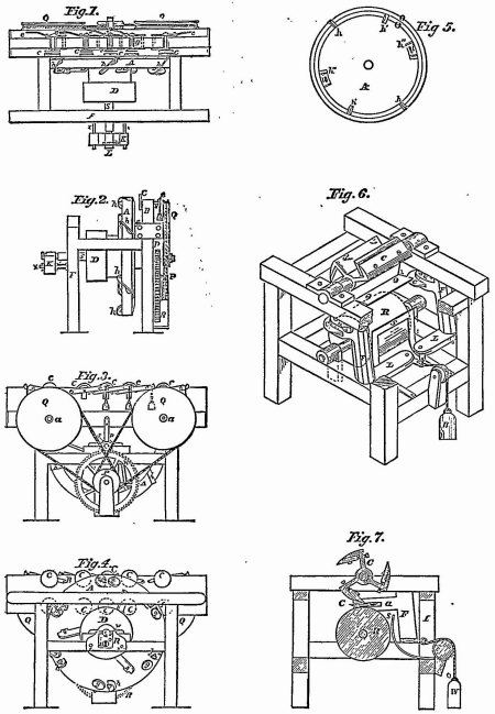
[Fig. 2 is a separate view of the planing-cylinder, with its knives or cutters; and fig. 3, an end view of one of the heads. E E are the revolving cutters, or tonguing and grooving wheels, and D D, whirls upon their shafts, which may be driven by bands, or otherwise, so as to cause said wheels to revolve in the proper direction.
[Fig. 4 is a side view of one of these wheels; fig. 5 is an end view of the tonguing-wheel; and fig. 6 an edge view of the grooving-wheel; the latter being each shown with two cutters in place. The number of cutters on these wheels may be varied, but they are represented as furnished with four. The cutters may he fixed on the sides of circular plates, with their edges projecting beyond the periphery of said plate.
{The edges of the plank, as its planed part passes the planing-cylinder, are brought in contact with the above-described tonguing and grooving wheels, which are so placed upon their shafts as that the tongue and groove shall be left at the proper distance from the face of the plank, the latter being sustained against the planing cylinder by means of the carriage or bed-plate, or otherwise, so that it can not deviate, but must be reduced to a proper thickness, and correctly tongued and grooved.
[In fig. 1, above referred to, only one carriage and one pair of cutter-wheels are shown, it not being deemed necessary to represent those on the opposite side, they being similar in all respects.
[Fig. 7 represents the same machine, with the axis of the planing-cylinder placed horizontally, and intended to operate on one plank only at the same time. A A is the frame; B B, the heads of the planing-cylinder; C C, the knives or cutters attached to said heads. To meet the different thicknesses or the planks or boards, the bearings of the shaft or cylinder may be made movable, by screws or other means, to adjust it to the work; or the carriage or bed-plate may be made so as to raise the board or plank up to the planing-cylinder. E and E' are the revolving cutters, or tonguing and grooving wheels, which are placed upon vertical shafts, having upon them pulleys, D D, around which pass belts or bands from the main drum, I, to which a revolving motion may be given by any adequate motive power.
[From the drum, I, a belt, L, passes also around the pulley, b, on the shaft of the planing-cylinder, and gives to it the requisite motion. There may in this machine be a horizontal carriage moved forward by a rack and Din-ion, in a manner analogous to that represented in fig. 1; but in the present instance the plank is supposed to be advanced by means of one of two pairs of friction or feed rollers, shown at f f; the uppermost, f f, of the pairs of rollers, may be held down by springs, or weighted levers, which it has not been thought necessary to show in this drawing, as such are in common use. The lowermost of these rollers may be fluled or made rough on their surfaces, so as to causa friction on the under side of the plank. M M' are pulleys on the axles of these lower rollers, which are embraced by bands, N N', which also pass around a pulley, O, on a shaft which crosses the frame A A, and has a pulley, T, on it, which is embraced by the belt, P, on a pulley, Q, on a shaft of the main drum, I; these bands and pulleys serve to give motion to the feed-rollers, as will be readily understood by inspecting the drawing. R R. are guide-strips, used in place of the rollers used for the same purpose, and also 336for bearing or friction rollers, when the machine is vertical, to direct one edge of the plank, and against its opposite edge; any pressure may be used equal to the weight of the board or plank, when worked in a vertical position. One of the cutter-wheels should be made adjustable, to adapt it to stuff of different widths.
[The planing-cylinder, and likewise the cutter or tonguing and grooving wheels, may be constructed in the manner represented in figs. 2, 3, 4, 5, and 6, and hereinbefore fully described. One of the heads of the planing-wheel may be made movable to accommodate its width to the width of the boards or plank to be planed.
[The respective parts of this machine may be varied in size, as may also the velocity of the motion of the planing-cylinders and cutter-wheels; but the following has been found to answer well in practice: The planing-cylinder, having four knives or cutters, may be twelve inches in diameter, and may make two thousand and upward revolutions in a minute. In a machine like that shown in fig. 7, the main drum, I, may be two feet in diameter, and may be driven with the speed of five hundred and upward revolutions in a minute. The pulleys on the planing-cylinder, and on the cutter-wheels, may be six inches in diameter. The plank should be moved forward at the rate of about one foot for every hundred revolutions of the cutter-wheel: and, of course, the diameter of the feed-rollers and of the pulleys by which they are turned must be so graduated as to produce this result. The size and speed of the above parts of this machine may be in some degree varied; but the above have been found to work well.
[Having thus fully described the parts and combinations of parts, and operation of the machine for planing, tonguing, and grooving boards or plank, and shown various modes in which the same may be constructed and made to operate without changing the principle or mode of operation of the machine, what is claimed therein as the invention of William Woodworth, deceased, is the employment of rotating planes, substantially such as herein described, in combination with rollers, or any analogous device, to prevent the boards from being drawn up by the planes when cutting upward, or from the reduced or planed to the unplaned surface, as described.
[And also the combination of the rotating planes with the cutter-wheels for tonguing and grooving, for the purpose of planing, tonguing, and grooving boards, etc., at one operation, as described, and also the combination of the tonguing and grooving cutter-wheels for tonguing and grooving boards, and at one operation, as described.
[And, finally, the combination of either the tonguing or the grooving cutter-wheel for tonguing or grooving boards, etc., with the pressure-rollers, as described, the effect of the pressure-rollers in these operations being such as to keep the boards, etc., steady, and prevent the cutters from drawing the boards toward the center of the cutter-wheels, whilst it is moved through by machinery. In the planing operation, the tendency of the plane is to lift the boards directly up against the rollers; but in the tonguing and grooving, the tendency is to overcome the friction occasioned by the pressure of the rollers.
[William W. Woodworth,
[Adm'r of William Woodworth, Deceased.
[Witnesses:
[James Milholland,
[Chas. M. Keller.]5
[For other cases involving this patent, see note to Bicknell v. Todd, Case No. 1,389.]
1 [Reported by Samuel Blatehford, Esq., and here reprinted by permission.]
2 [From 1 Fish. Pat Rep. 369.]
2 [From 1 Fish. Pat Rep. 369.]
3 [Planing Machine.
[Fig. 1 is a perspective representation of the principal operating parts of the machine. A A is the frame of the machine; it may be either of wood or iron, and vary in size according to the work to be done. B B, heads of the planing cylinder; and O C, the knives or cutter which extend from one to the other of said heads, to the peripheries of which they are attached by screws. The knives, C C, may be placed in a line with the axes, J, of the cylinder, or obliquely thereto, as may be preferred: in the latter case the edge should form the segment of a helix, b represents a pulley near the upper end of the axes, J. I represents a pulley or drum made to revolve by horse, steam, or other motive power, from which a belt may extend around the pulley b, to drive the planing cylinder and other parts of the machinery. G is the carriage, represented as being driven forward by means of a rack and pinion, H; against this carriage the plank K, which is to be planed, tongued, and grooved, is placed and made to advance with it.
[Fig. 2 is a separate view of the planing cylinder with its knives or cutters, and Fig. 3 an end view of one of the heads. E E are the revolving cutters or tonguing and grooving wheels; and D D, wheels upon their shafts which may be driven by bands or otherwise, in order that said wheels may revolve in the proper direction. Fig. 4 is a side view of one of these wheels; Fig. 5 is an edge view of the tonguing wheel, and Fig. 6 is an edge view of the grooving wheel—the latter being each shown with two cutters in place.]
[See note at end of case.]
4 [From 1 Fish. Pat Rep. 369.]
4 [From 1 Fish. Pat Rep. 369.]
5 [Published in 1 Fish. Pat. Rep. 629. as a note to Hogg v. Emerson, 11 How. (52 U. S.) 587.]
5 [Published in 1 Fish. Pat. Rep. 629. as a note to Hogg v. Emerson, 11 How. (52 U. S.) 587.]
This volume of American Law was transcribed for use on the Internet
through a contribution from Google. 