Case No. 3,176.
COOKE et al. v. NEW YORK CENT. & H. R. R. CO.
[4 Ban. & A. 398;1 16 O. G. 856.]
Circuit Court, N. D. New York.
July, 1879.
PATENTS—“RAILWAY SWITCH”—ANTICIPATION.
A patent for a railway switch, in the claims of which an important element is the rail sections used to guide the wheels from the back to the flange-supporting block, in an easy manner without any jarring or abrupt change of motion, and in a proper direction for the wheels to drop into the main track at the proper point, is not anticipated by a prior switch which had no rail-section or equivalent therefor.
[In equity. Suit by Charles L. Cooke and others against the New York Central & Hudson River Railroad Company to restrain alleged infringement of reissued letters patent No. 7,690, granted to plaintiffs May 22, 1877. The original patent was granted to C. L. Cooke November 21, 1871, and is numbered 121,158.]
Bowen, Rogers & Locke, for complainants.
J. Thomas Spriggs, for defendant.
BLATCHFORD, Circuit Judge. This suit is brought on reissued letters patent granted to the plaintiffs May 22d, 1877, for an improvement in railway-switches, the original patent having been granted to said Cooke, November 21, 1871.
The specification of the reissue says: “My invention relates to that class of switches which are provided with a device for preventing the wheels from running off the rails to the ground, when the switch has been improperly placed. The object of my invention is to construct a safety-switch of this class, which shall guide the wheels upon the track in a natural and easy manner, without any sudden or abrupt changes of motion, and which shall be constructed of substantially the same material of which the main track is composed, so as to avoid injury to or breakage of the wheels as they pass over the switch.
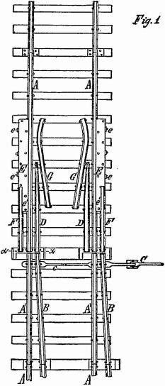
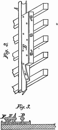
“The nature of my invention will be fully understood from the following description: In the accompanying drawing, Figure 1 is a top plan view of a switch provided with my improvements. Fig. 2 is a detached perspective view of the flange-supporter. Fig. 3 is a fragmentary cross-section in line X X, Fig. 1. Like letters of reference refer to like parts in each of the figures.
“A, A, represent the rails of the main track, and A′, A′, the main switch-rails, forming continuations thereof. B, B, represent the rails of the siding, connected with rails A′, A′, by rod C, operated by a lever C in the usual manner, so that the free ends of either the rails A′, A′, or B, B, may be placed opposite the main rails A, A. D represents two pointed rails arranged on the inner side of the main rails A, A, so as to form a continuation of the inner switch-rails. E represents the flange-supporting blocks arranged on the outer side of the main rails A, and F a rail section forming a continuation of the outer switch-rails and abutting against the flange-supporter E. The latter is preferably composed of a wooden body secured to the
main rails by bolts c, and a plate-iron covering secured to the wooden body by countersunk screws or rivets, or in any other suitable manner. The upper side of the flange-supporter, E, is made flush with the tread of the rails A and F, and of a width to extend to the outside of the tread of the rail F. e′ is an inclined or wedge-shaped lip, formed at the forward end of the flange-supporter E, between the rails A and F, as clearly shown in Figs. 1 and 2. G are two guide-rails arranged at an angle on the inner side of the pointed rails D and main rails A, and having their forward ends opposite the inclined lips e′ of the flange-supporter E, so that one wheel will be fully under the control of the guide-rails G before the other wheel leaves the rail-section F. The rear ends of the guide-rails G approach the main rails to such a distance as to cause the wheels running on the flange-supporter to cross the adjacent main rail and drop into the main track before the opposite wheel leaves the guide-rail G.
“When a locomotive or car comes in on the wrong track, in the drawing on the rails B B, the right-hand wheels will pass from the rail B upon the rail-section F, while the left-hand wheels will pass upon the pointed rail D. The rails D and F, being fixed in their relative position to the main track, guide the wheels along in a perfectly steady and safe manner until the flange of the right-hand wheel strikes the inclined lip e′ of the flange-supporter E, when the right-hand wheel begins to rise thereon, but is still held by the rail F. At the same time the left-hand wheel comes in contact with the guide-rail G, which gives both wheels a tendency to travel toward the main track, which tendency is increased as the right-hand wheel mounts the support or block E, and runs on the larger circle of its flange. Both wheels now travel under these combined influences toward the main track, and finally drop into the same without being subjected to any sudden change in their movement. The flange-supporter E, being composed of wood and an iron covering, has a certain degree of elasticity, and does not stiffen the main track as heavy cast parts do, thereby preventing the chipping off or breaking of the wheels as they run over the switch in ordinary use. The flange-supporting blocks E and rail-sections F, when worn out, are readily replaced by new ones without interfering with the use of the track.”
The claims, three in number, are as follows: “1. The combination, with the main-track rails A A and switch-rails B B, of the flange-supporting blocks E E, secured to the outer side of the main rails, and rail-sections F F, connecting the flange-supporting blocks with one or the other of the outer switch-rails, substantially as and for the purpose hereinbefore set forth. 2. The combination, with the main track rails A A and switch-rails B B, of the flange-supporting blocks E, secured to the outer side of the main rails and provided with inclined lips e′, and rail-sections F, points D, and guide-rails G, arranged as shown and described, substantially as and for the purpose hereinbefore set forth. 3. The combination, with the main-track rails A, pointed rails D, guide-rails G, and rail-sections F, all constructed of rails, of the flange-supporters E, constructed of wood, and provided with a covering of plate-iron, substantially as and for the purpose hereinbefore set forth.”
The rail-sections F F are an element of each of the three claims of the patent. It is conceded on the record that the switches used by the defendant, represented by the model W4, are substantially alike, in principle, construction and method of operation, to the switch patented to the plaintiffs. The only defence is want of novelty.
The defendant introduces a prior switch, Y2, called the White or Tyler switch. It had no rail-section and no equivalent therefor. This rail-section is an “important” and useful device in the plaintiffs' arrangement. It is arranged, as the plaintiffs' expert testifies, so as to guide the wheels from the track-rail to the flange-supporting block in an easy manner, without any abrupt change of motion or jars, and in a proper direction for the wheels to drop into the main track at the proper point. He adds: “This rail section locates the switch-point at a certain distance,
438greater or less, in front of the block, and enables the wheel to pass upon the inclined plane without any jar or jolt. This inclined plane at the front end of the block forms an obstruction to the passage of the wheel on that side, and retards the progress of that wheel to a greater or less extent, while the wheel on the other end of the axle, which does not encounter any obstruction, is free to move on. This inclined plane then causes the truck to turn on the centre-pin toward the side on which the inclined plane has come in contact with the wheel, and will cause the wheel to travel away from the proper or main track, and not toward the main track. This tendency of the wheel is counteracted by the section-rail on the outer side of the inclined plane, and the flange of the wheel is held in its proper place and confined by the section-rail until the wheel has reached the surface of the block. The tendency of the wheel to travel toward the main track on that side, by reason of that wheel running on its flange while the other wheel runs on its tread, does not come into play until after the wheel has mounted the block, because the concussion on striking the incline would be more apt to change the course of the wheel toward the wrong direction or away from the main track than the increased diameter of the wheel could turn it toward the main track, because the concussion will operate instantaneously, while the increased diameter of the wheel can affect the direction of the wheel only slowly or gradually, as the wheel runs along over the surface of the block. Furthermore, the increased diameter of the wheel is counteracted as the wheel passes over the incline, to a greater or less extent, for the reason that the wheel running up the incline has to travel a greater distance than the wheel running on its tread, in order to make it travel the same distance horizontally. The section-rail also reduces the distance that the wheel has to travel on its flange, and it relieves the guard-rail to a large extent, and prevents the wheel which runs on its tread from striking the guard-rail with great force when the other wheel strikes the incline, so that the wheels will pass over the switch, when misplaced, more smoothly and more safely than if the section-rail were not there.”
He further says that he does not find, in the White or Tyler switch, any of the combinations described in the plaintiffs' patent, or any equivalent mechanical device for the plaintiffs' rail-section.
The defendant's switch W4 embodies the first and second claims of the plaintiffs' patent and contains the section-rails, and they are not found in the White or Tyler switch. It is clear that the plaintiffs' improvements are patentable. Some evidence was put in as to an old switch, Z5, but it fails to show that the switch embodies the combinations claimed in the plaintiffs' patent.
There must be a decree for the plaintiffs for a perpetual injunction, and, under the stipulation of the parties, a decree for the plaintiffs for $3,750, damages for past infringements, and for costs.
1 [Reported by Hubert A. Banning, Esq., and Henry Arden, Esq., and here reprinted by permission.]
This volume of American Law was transcribed for use on the Internet
through a contribution from Google. 