Case No. 2,906.
5FED. CAS.—69
CLOUGH v. GILBERT & B. MANUF'G CO. et al.
[3 Ban. & A. 523;1 15 O. G. 1009; Merw. Pat. Inv. 225.]
Circuit Court S. D. New York.
Oct 14, 1878.
PATENTS—“GAS BURNERS”—CONSTRUCTION—EQUIVALENTS—COMBINATION—INFRINGEMENT.
1. The first claim in the patent to Clough, June 14th, 1870, for improvement in gas burners, includes the combination of the perforated burner with surrounding tube, irrespective of any method of regulating the escape of gas from the perforations, and is found in the patent to J. P. Barker, July 26th, 1870, who is the prior inventor of the same.
2. The employment of a slit extending down to the base of the burner, instead of small perforations at the base: Held, to be an equivalent, the structure and mode of operation of the combination being the same.
3. A combination, such as was embraced in the second claim of Clough's patent, being found to be old in the art, the claim was limited in construction so as to include the particular devices shown, and when so limited, the defendant's device did not infringe.
[See note at end of case.]
[In equity. Bill by Theodore Clough against the Gilbert & Barker Manufacturing Company and others for alleged infringement of letters patent.
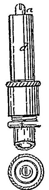
[The following is a drawing of the Clough burner:]
Fig 1
Fig 2
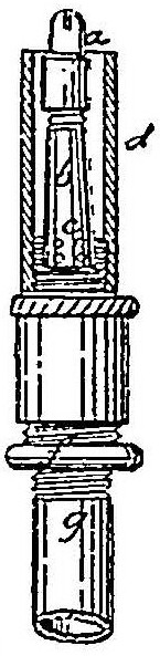
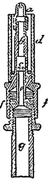
Fig 3
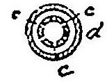
Fig 4
George H. Yeaman, for complainant.
William Stanley, for defendants.
BLATCHFORD, Circuit Judge. This suit is founded on letters patent No. 104,271, granted to the plaintiff, June 14th, 1870, for an improvement in gas-burners. The specification says:
“My invention relates more particularly to burners for burning illuminating gas made by saturating gas with vapors of gasoline, commonly called air-gas. It has been found that common bat-wing or fish-tail burners are not adapted to burning this gas as ordinarily made, owing to the variable density of the gas coming from the generating apparatus.
“The object of my improvement is to adapt the slitted or bat-wing burner to the burning of air-gas.
“Said improvements consist first in perforating the base of the burner-tube with small holes or passages for gas to escape at the base of the burner, and surrounding the burner with a tube open at the top, but closed at the bottom, and united to the burner below the perforations in the burner-tube. It is more convenient to screw the tube to the burner, but it may be attached in any suitable manner. Second, in regulating the escape of the gas from the perforations at the base of the burner by a sliding tubular valve
1088or cut-off, introduced into the burner-tube at the base and extending upward within it, the position of the tubular valve being regulated by a screw. These improvements, by furnishing a regulated supply of gas outside of the burner, but directed to the tip of the burner by the surrounding tube, give steadiness and increased illuminating power to the flame of the bat-wing burner, and make it a desirable burner for burning air-gas.
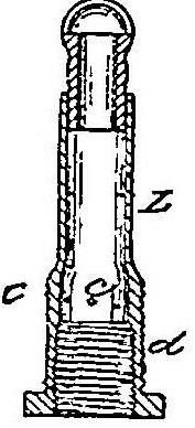
“The drawings represent a bat-wing burner as improved by me.
“Figure 1 represents an elevation of my improved burner attached to a short piece of gas-pipe; Fig. 2, a view showing the surrounding tube in section and the burner therein; Fig. 3, a vertical section through the burner and tube; Fig. 4, a transverse section through the base of the burner-tube.
“Letter a represents the burner-tip; b, the burner-tube; c, perforations at the base of burner-tube; d, the surrounding tube screwed to base of burner-tube; e, the tubular valve extending up in the burner-tube, and operated by an annular screw, f, attached to the lower end. Said annular screw, besides having a screw to work in the base of the burner, has an internal screw, by which it and the burner are attached to the gas-pipe, as clearly shown in Fig. 3 and the other drawings, the gasway being through the annular screw and tubular valve to the burner. As the burner is connected to the gas-pipe, g, by means of the annular screw, the adjustment of the gas escaping through the perforations of the burner-tube, is easily made by turning the burner upon the annular screw.
“I claim, as my invention and improvement in air-gas burners, the bat-wing burner perforated at the base, in combination with the surrounding tube, substantially as described. Also, in combination with the bat-wing burner perforated at the base and surrounding tube, the tubular valve for regulating the supply of external gas to the burner, substantially as described.”
The defendants, in their answer, set up that they have not infringed the patent, and that it is void for want of novelty. At the request of both parties the court ordered a trial, at law, in this court, of two questions:
First Whether or not the complainant is the first and original inventor of the improvement in gas-burners for which the first above-named patent has been granted to him.
Second. Whether or not the gas-burners manufactured by the defendants are substantially identical with those described in the complainant's patent and schedule thereto annexed, in their construction and mode of operation.
The issues were tried before Judge Ship-man and a jury, and the jury answered both of the questions in the affirmative. Afterward, on a case made, the defendants moved before Judge Shipman for a new trial on the ground that the verdict was against the weight of the evidence. He denied the motion in a written opinion, in which he stated that the weight of the evidence on the question of infringement was not such as to justify him in granting a new trial, and that he was satisfied with the conclusion of the jury on the question of priority. He afterward signed and filed a certificate, that, in his opinion, the verdict, on both questions, was sustained by the evidence given.
The burners made by the defendants were made in accordance with the description of the first form of burner described in the specification of letters patent [No. 105,768] granted to John F. Barker, one of the defendants, July 26th, 1870, for an improvement in gas-burners. The drawings of that patent consist of ten figures, which are thus referred to in the specification:
Fig 1
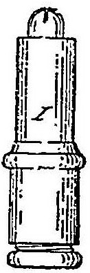
Fig 2
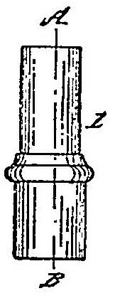
Fig 3
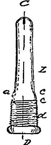
Fig 4
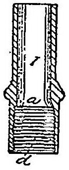
Fig 5
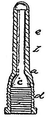
Fig 6
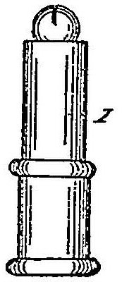
Fig 7
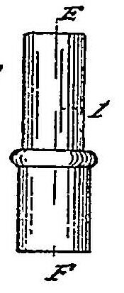
Fig 8
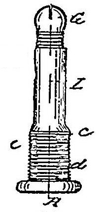
Fig 9
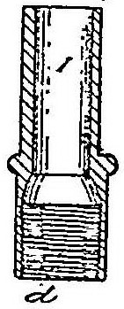
Fig 10
“Figure 1 is a side view of one modification of my invention. Fig. 2 is a side view
1089of the shell. Fig. 3 is a side view of the burner. Fig. 4 is a vertical longitudinal section of the shell through line A B of Fig. 2. Fig. 5 is a vertical longitudinal section of the burner through line C D of Fig. 3. Fig. 6 is a side view of another modification of my invention. Fig. 7 is a side view of the shell. Fig. 8 is a side view of the burner. Fig. 9 is a vertical longitudinal section of the shell through line B F of Fig. 7; and Fig. 10 is a vertical section through line G H of Fig. 8.”
The specification goes on to say: “My invention relates to a device for regulating the flow of carburetted air or gas from the burner to its point of combustion; and it consists of a burner having a screw-thread made upon its lower part upon which is fitted, to turn freely thereon, a shell or tube, also having a screw-thread upon its interior lower part; and the bore of said tube or shell is somewhat larger in diameter than the diameter of the upper part of the burner upon which it turns. A series of perforations is made in the lower part of the burner, so that, when the burner is made or set for the combustion of carburetted air or gas of any certain quality, the flame may be increased or diminished by turning the shell either up or down, as the case may be; the shell, in its movements up or down, either closing or opening the holes or perforations, and letting out or stopping the flow of the gas through the said holes, as it is moved up or down. In the use of carburetted air for illuminating purposes it is almost always the case that, when the gasoline is first placed within the generator, it gives off a much greater amount of vapor, and the air, in passing through the generator, absorbs a greater amount of the carbon, and conse quently becomes more thoroughly charged with, and is much richer in, the illuminating qualities of the gasoline than when the generator has been charged for a greater length of time; and, as a result, the carburetted air is sometimes too rich to make a desirable light, with the same amount passing out of the burner, and, at other times, as when the generator has been charged a longer time, the carburetted air flowing through the burner is deficient in illuminating power, and the light or flame produced is not uniform in its power or steadiness, and is sometimes liable to produce a smell of smoke, when too rich in carbon. My invention is designed to obviate all difllculty in this respect, as the burner is set, or made to let out at the tip the minimum quantity of gas that will produce a good flame, and, as the gasoline remains longer in the generator and becomes weaker in its illuminating qualities, the outer tube or shell may be turned so as to let out more gas and increase the flame, without liability to smoke.
“That others skilled in the art may be enabled to make and use my invention, I will now proceed to describe its construction and mode of operation.
“In the drawing, L represents the main part of the burner, which is made similar to the common burner, except that the lower part has a screw-thread made upon the outside and inside. Figs. 1, 2, 3, 4, and 5 represent one modification, in which L is the burner, having the usual screw-thread made upon the lower interior part, by which to secure it to the pipe. At a′ is a conical shoulder or seat upon the exterior (shown in Figs. 3 and 5), and a screw-thread, d′, made upon the exterior of the lower end, and the small holes c are made either at the seat a′ or just below it I is a shell or tube, the inside diameter of its upper part being somewhat greater than the outside diameter of the part Ii, and upon the interior of the tube at a is a conical-shaped seat, made to fit upon the exterior seat a upon the burner L. A screw-thread, d, is made upon the interior of the lower part of the tube I, which fits the thread d′ upon the exterior of the burner L.
“The operation of this modification is as follows: When the tube I is turned entirely on to the burner L, the inner seat, a, fits down upon the shoulder a of the burner L, and the only place of egress for the gas is through the slot at the tip. When the gasoline is fresh or new this slot will be quite sufficient to supply the flame; but, as the gasoline becomes more exhausted of carbon, the tube or shell I may be turned up a little, so that the seat a shall be raised slightly from the shoulder a′, and more or less of the gas will pass out through the holes c, and pass up between the tube I and the burner L as the tube I is turned up or down, and when the gasp which escapes through the holes c and passes up between the tube and burner, reaches the top, it unites with that passing out of the slot at the tip, increasing the volume and flame. In this device the gas, after passing out through the holes c, is prevented from passing down between the tube and burner by the screw-threads d and d′ upon the inside of the tube and outside of the burner.
“;In the modification shown in Figs. 6, 7, 8, 9, and 10 both the burner and the regulating-tube are similar to that already described, except that the thread d′ upon the outside of the burner L is carried up higher and the holes c are made below the top of the outer thread but above the top of the inside thread. The thread upon the inside of the tube I is not so long as the outside thread upon the burner L, but is considerably less, so that when the tube I is turned entirely down on the burner the holes will be above the thread on the inside of the tube, and there is no inside seat in the tube I to operate upon a beveled or conical exterior shoulder upon the burner L, as in the other modification.
“The operation of this modification is as follows: If the flame be too weak, the tube I is turned down upon the burner L until the top of the inside thread of the tube begins to pass below the holes c, when the gas
1090will escape and pass up between the tube and burner, and increase the flame as before. If it should be desirable to stop the escape of gas through the holes c, it is only necessary to turn up the tube upon the burner, and, when the thread inside the tube covers the holes c, then there will be no escape of gas.
“It will be seen that the principles of the operation of both modifications are very much alike, and are intended to accomplish the same object, although the tube turns up in the first case to let out more gas, while it turns down in the second case, both being equivalent, however, in their operation, and accomplishing the same result.
“I am aware that gas-burners have been heretofore made to give an additional supply of gas to the flame, but in those that I have seen they consisted of more pieces, and were considerably more expensive to manufacture, and in their operation the burner revolved with the tube, thus causing the flame to revolve also. This is very objectionable, as it is often desirable to have the name stand in one particular direction. In this device the flame does not ton in the least, while the whole burner may consist of only two pieces, and is cheaply made, and its operation and effect are perfect.”
The claim of that patent is: “An improved gas-burner, consisting of the burner or pillar L, having holes c c therein, and provided with the movable or adjustable shell or tube I, all constructed and operating substantially as and for the purposes herein described and specified.”
After such certificate was signed and filed by Judge Shipman, the Gilbert & Barker Manufacturing Company, defendants in this suit, brought a suit in equity in this court, as owners of the said patent granted to John P. Barker, for the infringement of the same against Clough, the plaintiff in this suit, alleging as the infringement the making and selling of burners constructed exactly like the two forms described in the patent to Barker. The only testimony taken directly In the present suit brought by Clough is that taken on the trial before the jury, and embodied in a case made, on which the motion for a new trial was made. It is stated in the brief in this case, on the part of the defendants, that this case is brought to a hearing on the proofs and the verdict on such jurytrial, and on the proofs taken in the suit against Clough, and that such latter proofs are, by stipulation, used on this hearing. I am not furnished with any such stipulation, but I assume that both parties understand that there is one, verbal or written.
In the record in the suit brought against Clough I find the following entry:
“It is agreed by the counsel that upon the trial of this cause either party may read such parts of the testimony, as he wishes, given in the suit of Theodore Clough against the Gilbert & Barker Manufacturing Company, and contained in the printed case and exceptions in that suit, as evidence herein, subject to the same objections taken on the trial at law in that suit, and that, if the court will consent, the two causes may be tried together, when the case of Clough against the said company, or any motion for final decree therein, is reached and heard. This stipulation is without prejudice to the right of either party to take further testimony in this cause.”
The stipulation contained in such entry is not a stipulation for the use, on this hearing, of any proofs taken in the suit brought against Clough, but I shall assume that all such proofs are to be regarded as used and read on this hearing, and, from the brief of the counsel for Clough in the two suits, I infer such to be his view.”
The first claim of the Clough patent relates to the first of the two improvements set forth in the specification, and the second claim relates to the second of such improvements. The combination of the perforated burner with the surrounding tube, irrespective of any method of regulating the escape of the gas from the perforations, is the subject of the first improvement and of the first claim. The office of that combination is, as the specification states, to enable the surrounding tube to direct to the tip of the burner the gas which comes through the perforations, such tube being open at the top and closed at the bottom, and united to the burner below the perforations. The combination of the regulating-valve with the perforated burner and the surrounding tube is the subject of the second improvement and of the second claim. Moreover, if the means of regulation are to be regarded as entering as an element into the first claim, there is no difference between the two claims.
The two forms of burner, A and B, alleged; to be infringements in this case, are both of them substantially like the first form of burner described in the patent to Barker. In both of them the outside tube turns up to let out more gas. It is very clear that each of these burners contains the combination claimed in the first claim of the Clough patent. It is a more serious question whether either of these two burners contains the combinations claimed in the second claim of the Clough patent. They have no sliding tubular valve or cut-off introduced into the burner-tube at the base, and extending upward within it. In them the tubular valve forms part of the surrounding tube. Such valve goes to or leave its seat by screwing up or down the surrounding tube. The surrounding tube cannot be permanently attached to the burner, but must be capable of movement, as it carries the valve. In the arrangement shown in the Clough patent the surrounding tube may be permanently attached to the burner, because the tubular valve is not carried by the surrounding tube, but is a third and separate instrument carried
1091by an adjustable cylinder inserted with in the burner from below. Moreover, in the arrangement shown in the Clough patent the burner and surrounding tube revolve together in adjusting their position in reference to that of the tubular valve, so as to let on or turn off the supply of gas through the perforations in the base of the burner, and by the revolution of the burner the flame also revolves. In the burners A and B the revolution of the surrounding tube regulates the supply of gas through such perforations, and the burner never revolves, nor does the flame.
The combination covered by the first claim of the plaintiff's patent is, I think, found in the Horace R. Barker burners, the existence of which prior to the plaintiff's invention is satisfactorily proved. In those burners the burner was a bat-wing burner perforated at the base. The perforations did not consist of small holes, but the stem of the burner was slitted ail the way down to the base, allowing the gas to escape through the whole length of the slit. There was a surrounding tube united to the burner below the lower end of the slit. The burner-stem had a cone near its top, and when the surrounding tube was screwed so as to be in a certain position with reference to such cone, the effect was to direct to the tip of the burner the supply of gas coming through the slit below, the surrounding tube being open at the top and closed at the bottom, and the flame was thickened and a ring of flame was formed. The structure and mode of operation of the combination were the same as those of the combination covered by the first claim of the plaintiff's patent The fact that the perforations in the Horace R. Barker burner existed not only at the base, but were continued in the form of a slit all the way up, makes no difference. Nor does it make any difference that the Horace R. Barker burner had a cone near its top. The first claim of the plaintiff's patent is broad enough to cover the Horace R. Barker burner, and that claim must be held to be invalid for want of novelty.
In respect to the second claim of the plaintiff's patent, it is shown that in the Horace R. Barker burner, by the screwing down of the surrounding tube-socket it impinged against the cone near the top of the burner; cut off the supply of gas which came through the slit below; and that the raising of the tube, so that it did not bear against the cone, allowed a supply of gas to come from below. Thus there was regulation, and by a valve arrangement. In view of the existence of that burner, which contained the combination of a bat-wing burner, perforated at its base, with a surrounding tube in substance like that of the plaintiff's patent, and a tubular valve for regulating the supply of external gas to the burner, the construction of the second claim of the plaintiff's patent must be such as to limit that claim to the form of tubular valve which he describes, namely, one in the interior of the burner-tube, arid not forming part of the surrounding tube. Under this construction, the second claim of the plaintiff's patent is not infringed by the burners A and B, nor by any burner constructed in accordance with any description of a burner In the John F. Barker patent.
I have come to the foregoing conclusions after a careful examination of all the evidence given in this suit, and in the suit brought against Clough, and of the exhibits introduced, and with reluctance, because of the issue of the jurytrial, and of the expressed views of the judge who presided at it. But, being satisfied that the law and the evidence require a decree contrary to the verdict on the jurytrial, I am authorized and bound to pronounce such decree.
The bill is dismissed, with costs.
[NOTE. For another case involving this patent, see Clough v. Gilbert & B. Manuf&g Co., 106 U. S. 166, 1 Sup. Ct. 188.
[The complainant appealed to the supreme court, which reversed the decree dismissing the bill, and remanded the cause with directions to enter a decree for appellant for an account and injunction as prayed in the bill.
[The opinion was delivered by Mr. Justice Blatchford, and, after establishing the validity of the Clough patent, holds that the second claim of the same patent was infringed by defendants. Clough v. Gilbert & B. Manuf'g Co., 106 U. S. 166, 1 Sup. Ct 188.]
1 [Reported by Hubert A. Banning, Esq., and Henry Arden, Esq., and here reprinted by permission.]
This volume of American Law was transcribed for use on the Internet
through a contribution from Google. 