This library of books, audio, video, and other materials from and about India is curated and maintained by Public Resource. The purpose of this library is to assist the students and the lifelong learners of India in their pursuit of an education so that they may better their status and their opportunities and to secure for themselves and for others justice, social, economic and political.
This item has been posted for non-commercial purposes and facilitates fair dealing usage of academic and research materials for private use including research, for criticism and review of the work or of other works and reproduction by teachers and students in the course of instruction. Many of these materials are either unavailable or inaccessible in libraries in India, especially in some of the poorer states and this collection seeks to fill a major gap that exists in access to knowledge.
For other collections we curate and more information, please visit the Bharat Ek Khoj page. Jai Gyan!
IRC:SP:99-2013
Published by:
INDIAN ROADS CONGRESS
Kama Koti Marg,
Sector-6, R.K. Puram,
New Delhi-110 022
November, 2013
Price : ₹ 1200
(Plus Packing & Postage)
PERSONNEL OF THE GENERAL SPECIFICATIONS AND STANDARDS COMMITTEE (GSS)
(As on 6th August, 2013)
| 1. | Kandasamy, C. (Convenor) |
Director General (RD) & Spl. Secretary, Ministry of Road Transport & Highways, New Delhi |
| 2. | Patankar, V.L. (Co-Convenor) |
Addl. Director General, Ministry of Road Transport & Highways, New Delhi |
| 3. | Kumar, Manoj (Member Secretary) |
Chief Engineer (R) (SR&T), Ministry of Road Transport & Highways, New Delhi |
| Members | ||
| 4. | Dhodapkar, A.N | Chief Engineer (Retd.), MORTH, New Delhi |
| 5. | Das, S.N. | Addl. Director General (Mech.), MORTH New Delhi |
| 6. | Datta, P.K. | Director-Corporate Development, M/s TransAsia Infrastructure Pvt. Ltd., New Delhi |
| 7. | De, Dr. D.C. | Executive Director, Consulting Engineering Services (India) Pvt. Ltd., New Delhi |
| 8. | Duhsaka, Vanlal | Chief Engineer, PWD Highways, Aizwal |
| 9. | Joshi, L.K. | Former Secretary, MORTH, New Delhi |
| 10. | Kadiyali, Dr. L.R. | Chief Executive, L.R. Kadiyali & Associates, New Delhi |
| 11. | Kumar, Ashok | Chief Engineer (Retd.), Ministry of Road Transport & Highways, New Delhi |
| 12. | Kumar, Dr. Kishor | Chief Scientist, Geotechnical Engg. Dn., CRRI, New Delhi |
| 13. | Mandpe, P.S. | Chief Engineer (NH), PWD Maharashtra |
| 14. | Narain, A.D. | Director General (RD) & AS (Retd.), MORTH, Noida |
| 15. | Pandey, I.K. | Chief General Manager (Tech.), National Highways Authority of India, Bhopal, Madhya Pradesh |
| 16. | Patwardhan, S.V. | Advisor, Madhucon Project, New Delhi |
| 17. | Puri, S.K. | Director General (RD) & Spl. Secretary, MORTH (Retd.), New Delhi |
| 18. | Rajoria, K.B. | Engineer-in-Chief (Retd.), Delhi PWD, New Delhi |
| 19. | Rao, PR. | Vice President, Soma Enterprises Ltd., Gurgaon |
| 20. | Reddy, K. Siva | Engineer-in-Chief (R&B), Admn. & National Highways, Hyderabad, Andhra Pradesh |
| 21. | Selot, Anand | Former Engineer-in-Chief, PWD Madhya Pradeshi |
| 22. | Sharma, D.C. | Sr. Principal Scientist and Head Instrumentation Division, CRRI, New Delhi |
| 23. | Sharma, D.D. | Chairman, M/s D2S Infrastructure Pvt. Ltd, New Delhi |
| 24. | Sharma, Rama Shankar | Chief Engineer (Retd.), MORTH, New Delhi |
| 25. | Sharma, S.C. | Director General (RD) & AS (Retd.), MORTH, New Delhi |
| 26. | Shrivastava, Palash | Director, IDFC, New Delhi |
| 27. | Singh, Nirmal Jit | Director General (RD) & Spl. Secretary, MORTH (Retd.), New Delhi |
| 28. | Sinha, A.V. | Director General (RD) & Spl. Secretary, MORTH (Retd.), New Delhi |
| 29. | Sinha, N.K. | Director General (RD) & Spl. Secretary, MORTH (Retd.), New Delhi |
| 30. | Tamhankar, Dr. M.G. | Director-Grade Scientist (SERC-G) (Retd.), Navi Mumbai |
| 31. | Tandon, Prof. Mahesh | Managing Director, Tandon Consultants Pvt. Ltd. |
| 32. | Vasava, S.B | (Vice-President, IRC) Chief Engineer (P) & Addl. Secretary, R&B Deptt. Gandhinagar, Gujarat |
| 33. | Velayutham, V. | Director General (RD) & Spl. Secretary, MORTH (Retd.), New Delhi |
| 34. | Verma, Maj. V.C. | Executive Director-Marketing, Oriental Structure Engineers Pvt. Ltd., New Delhi |
| 35. | Rep of NRRDA | (Pateriya, Dr. I.K.) Director (Technical), NRRDA, NBCC Tower, Bhikaji Cama Place, New Delhi |
| 36. | The Dy. Director General | (Lal, B.B.) Chief Engineer, DDG D&S Dte. Seema Sadak Bhawan, New Delhi |
| 37 | The Chief Engineer (NH) | PWD Jaipur (Rajasthan) |
| Ex-Officio Members | ||
| 1. | Kandasamy, C. | Director General (Road Development) & Special Secretary, MORTH and President, IRC, New Delhi |
| 2. | Prasad, Vishnu Shankar | Secretary General, Indian Roads Congress, New Delhiii |
Recognizing the need for expeditious development of Access Controlled Facilities simultaneously ensuring safe and high speed travel which interalia improves the productivity of road transport system, it was decided by the Ministry of Road Transport & Highways and the Planning Commission through a series of meetings during December 2012 and January 2013 that a standard Manual of Specifications and Standards for Expressways should be brought out by the Indian Roads Congress (IRC). Accordingly, the IRC formulated the proposal and the task for the same was entrusted to IRC by the Ministry of Road Transport & Highways on 11th February, 2013. An Expert Group comprising of following experts was constituted by IRC for the preparation of the Manual:-
| 1. | Shri S.C. Sharma | Team Leader |
| 2. | Shri DP. Gupta | Member |
| 3. | Shri R.S. Sharma | Member |
| 4. | Dr. L.R. Kadiyali | Member |
| 5. | Shri Kiyoshi Dachiku | Member |
| 6. | Ms Neha Vyas | Member |
The Ministry of Road Transport & Highways constituted a Peer Review Group under the Chairmanship of Director General (Road Development) & Special Secretary having members representing all categories of stakeholders.
The Expert Group prepared a Technical Note on Critical Issues which was discussed during the Workshop organized by the MORTH on 22nd February, 2013 and also in Planning Commission on 6th March, 2013. The Critical Issues were deliberated, discussed and frozen during these two meetings, which enabled the Expert Group to move forward.
It was decided that the Manual should be structured on the lines of the existing Manual of Specifications and Standards for Four-laning of Highways published by IRC. The expressways need to be planned as fully access controlled highways where entry and exit points are provided at pre-determined locations. The Manual is intended mainly for new/green field expressways projects. This Manual is not applicable for design of expressways in urban areas andin hilly terrain. Due consideration has been given to conservation of material and environmental aspects as well. As a departure from the existing guidelines, the Manual professes near ground level expressways in the plain terrain and with moderate cutting and fillings in the rolling terrain.
The design considerations require that this type of expressways is constructed where flood, drainage or water table do not pose any problem and due care is taken from drainage point of view while keeping the expressway level close to the existing ground level.
The side approach roads should invariably cross over the expressway facility to maintain the sanctity of access controlled features.1
The Draft Version 1 of the Manual prepared by the Expert Group was discussed by the Peer Review Group during its second meeting held on 26th May, 2013. The comments of the Peer Review Group were suitably incorporated by the Expert Group in Draft Version 2, which was placed before the H-7 Committee and the G-1 Committee of IRC. The H-7 Committee (list of the members appended) approved the draft in its 4th meeting and the comments of the same were also incorporated by the Expert Group and placed the modified version before G-1 Committee. The G-1 Committee constituted a Sub-Group under the Chairmanship of Shri Ashok Kumar with the following members:-
The G-1 Committee (list of the members appended) finally approved the Draft Manual on 27th July, 2013. The GSS Committee during its meeting held on 6th August, 2013 approved the draft Manual. The final version of Manual was considered, deliberated and approved by IRC Council during its 200th Council Meeting held at New Delhi on 11th& 12thAugust, 2013 after taking on board the comments offered by the Members.2
This Manual is applicable for the construction of Expressways (four lanes, six lanes or eight lanes) through Public Private Partnership (PPP) mode. The scope of work shall be as defined in the Concession Agreement. This Manual shall be read harmoniously with the intent of the Concession Agreement.
This Manual is intended mainly for Expressways planned as green field projects. For this purpose, the Expressway is defined as an arterial highway for motorised traffic, with divided carriageways for high speed travel, with full control of access and provided with grade separators at location of intersections. Generally, only fast moving vehicles are allowed access on Expressways. They are inter-city Expressways located in open country outside the built-up area. The alignment may, however, pass through isolated small stretches of built-up area as long as the character of the Expressway as a whole does not change. The Manual is not directly applicable to the design of Expressways in urban areas and in hilly terrain.
The Project Expressway and the project facilities shall conform to the requirements of design and specifications set out in this Manual, which are the minimum prescribed. The project report and other information provided by the Authority1 shall be used by the Concessionaire only for his own reference and for carrying out further investigations. The Concessionaire shall be solely responsible for undertaking all the necessary surveys, investigations and detailed designs in accordance with good industry practice and due diligence, and shall have no claim against the Authority for any loss, damage, risks, costs, liabilities or obligations arising out of or in relation to the project report and other information provided by the Authority.
At least two weeks prior to commencement of the work, the Concessionaire shall draw up a Quality Assurance Manual (QAM) covering the Quality System (QS), Quality Assurance Plan (QAP) and documentation for all aspects of the bridge and road works and send three copies each to the Independent Engineer (IE) for review. The class of quality assurance shall be Extra High QA (Q-4) for all aspects of the project covering project preparation, design and drawings, procurement, materials and workmanship (Refer IRC:SP:47 and IRC:SP:57).
1 Authority/Government/Client3
The Codes, Standards and Technical Specifications applicable for the design and construction of project components are
Latest version of the Codes, Standards, Specifications and Amendments thereto notified/published at least 60 days before the last date of bid submission shall be considered applicable.
The terms ‘Ministry of Surface Transport’, ‘Ministry of Shipping, Road Transport & Highways’ and Ministry of Road Transport and Highways’ or any successor to or substitute thereof shall be considered as synonymous.
The terms ‘Inspector’ and ‘Engineer’ used in MORTH Specifications shall be deemed to be substituted by the term “Independent Engineer”, to the extent it is consistent with the provisions of the Concession Agreement and this Manual. The role of the Independent Engineer shall be as defined in the Concession Agreement.
In case of any conflict or inconsistency in the provisions of the applicable IRC Codes, Standards or MORTH Specifications, the provisions contained in this Manual shall apply.
All items of building works shall conform to Central Public Works Department (CPWD) Specifications for Class 1 building works2 and standards given in the National Building Code (NBC). For the Project Expressway through the state entity, to the extent specific provisions
2 The State Government may prescribe concerned State PWD Specifications, if so desired.4
for building works are made in IRC/MORTH Specifications, the same shall prevail over the CPWD/NBC provisions. For this purpose, building works shall be deemed to include toll plaza complex, road furniture, roadside facilities, landscape elements and/or any other works incidental to the building works.
The requirements stated in the Manual are the minimum. The Concessionaire may, however, adopt international practices, alternative specifications, materials and standards to bring in innovation in the design and construction provided they are better or comparable with the standards prescribed in the Manual. The proposed alternative specifications and techniques, including those which are not included in the MORTH/IRC Specifications shall be supported with authentic standards and specifications mentioned below:
United States of America (USA), Canada, United Kingdom (UK), France, Germany, Sweden, Denmark, Norway, the Netherlands, Spain, Australia, New Zealand, Japan and South Africa.
Such a proposal shall be submitted by the Concessionaire to the Independent Engineer. In case the Independent Engineer is of the opinion that the proposal submitted by the Concessionaire is not in conformity with any of the international standards or codes, then he will record his reasons and convey the same to the Concessionaire for compliance. A record shall be kept by the Independent Engineer of the non-compliance by the Concessionaire of the minimum Specifications and Standards specified in the Manual. Adverse consequences, if any, arising from any such non-compliance, shall be treated as “Concessionaire Default” and shall be dealt in accordance with the provisions of the Concession Agreement.
Certain paras (full or part) in Sections 1 to 15 of this Manual refer to the Schedules of the Concession Agreement. While finalizing the feasibility/project report for the Project Expressway, and the scope of the project, each of these paras should be carefully examined and addressed by the Authority with a view to making appropriate provisions in the Schedules of the Concession Agreement. (A list of the paras that refer to such Schedules has been provided at Appendix-2 for ready reference).5
The Project Expressway shall be planned as a “fully access controlled highway” where entry to and exit from the Expressway shall be provided only at pre-determined locations through properly designed entry/exit ramps and/or from interchanges. In doing so, the Concessionaire shall take measures to overcome the physical and operational constraints and plan, design and construct the Project Expressway using appropriate methods, management techniques and technologies. General considerations shall, without being limited to, be as follows:
The number of lanes to be provided for the Project Expressway shall be specified in Schedule-B of the Concession Agreement. It shall be developed in accordance with the typical cross-sections given in Para 2.16 of Section-2. Where only four lane (2×2) or six lane (2×3) carriageway is specified initially with depressed median, placement of the divided carriageway shall be as shown in the typical cross-sections (Fig. 2.1(a) and Fig. 2.1(b)). In this situation, the width of median shall be increased by multiple of 3.75 m for each additional lane to allow widening of the carriageway on the right side of the inside lane to achieve the ultimate eight lane carriageway (with 15 m wide depressed median) as and when required in future.
In the case of flush median, future widening shall be done on outer side.
The Project Expressway shall be designed to provide for high level of safety and operational efficiency for the movement of large volumes of traffic at high speed. Alignment design, geometrics, cross-sectional features, structures, road signage, markings, advance information system, and other traffic safety and management features and tolling system shall be designed to conform to the best standards and international practices to achieve a consistent, safe and efficient design to cater for highest safety to the user and meet the intended functions of the Project Expressway. Interchanges, exits and entrances should be tested for ease of operation and for route continuity from a driver’s point of view.
All designs shall be structurally safe to ensure that the Project Expressway or any part thereof (for example embankment, pavement, interchanges, retaining structures, bridges, culverts, etc.) does not collapse (global stability) nor its serviceability/performance (for example settlement, riding quality, undulations, deflections, etc.) deteriorates below acceptable level as prescribed in Schedule-K of the Concession Agreement.
The Project Expressway shall not only be safe but also durable. This would mean that the deteriorating effects of climate and environment (for example6 wetting and drying, freezing and thawing, rainfall, temperature differences, aggressive environment leading to corrosion, etc.) in addition to the traffic shall be duly considered in design and construction to make the Project Expressway durable.
The planning, design and construction of the Project Expressway shall be such that its construction does not have adverse impact on the environment, ecology and does not disrupt the lives and business activities of the people living close to the Project Expressway. Appropriate measures shall be taken as specified in Section-14 of this Manual.
The Concessionaire shall develop, implement and administer a surveillance and safety programme for providing a safe environment on or about the Project Expressway, and shall comply with the safety requirements set forth in the Concession Agreement.
Before taking up any construction or maintenance operation/work, the Concessionaire shall prepare a Traffic Management Plan for each work zone and furnish it to the Independent Engineer for comments duly incorporating the following:
The Concessionaire shall set up field laboratory for testing of materials and finished products as stipulated in Clause 120 of MORTH Specifications. He shall make necessary arrangements for additional/confirmatory testing of any materials/products at a government accredited laboratory, for which facilities at site laboratory are not available.7
The Concessionaire shall carry out tests/monitor various parameters impacting the environment of the Project Expressway keeping in view the guidelines of the Ministry of Environment and Forests and submit proposals for mitigation of adverse environment impact including provision of noise barriers, etc. for review and comments of the IE, and undertake implementation of the proposals in consultation with the IE.
The details of the new utilities which are to be constructed or provided for along or across the Project Expressway shall be as specified in Schedule-B of the Concession Agreement. No utility should be situated under any part of the roadway, except where the utility crosses the Expressway. Such utilities shall cross through a culvert.
In cases where the Concessionaire is required to send any drawings or documents to the Independent Engineer for review and comments, and in the event such comments are received by the Concessionaire, it shall duly consider such comments in accordance with the Concession Agreement and Good Industry Practice for taking appropriate action thereon. The correspondence between the Concessionaire and the Independent Engineer shall be deemed valid only if a copy thereof is endorsed to and received by the Authority.
Unless specified otherwise in this Manual, the definitions contained in the Concession Agreement shall apply.
The design speeds given in Table 2.1 shall be adopted for various terrain classifications. (Terrain is classified by the general slope of the ground across the Expressway alignment).
| Nature of Terrain | Cross Slope of the Ground | Design Speed (km/hr) |
|---|---|---|
| Plain | Less than 10 percent | 120 |
| Rolling | Between 10 and 25 percent | 100 |
Short stretches (say less than 1 km) of varying terrain met with on the alignment shall not be taken into consideration while deciding the terrain classification for a given section of the Project Expressway. Where an intervening stretch is classified as hilly/mountainous stretch and it may not be expedient from economic and environmental consideration to adopt even standards applicable to rolling terrain, a lower design speed of 80 km/h consistent with the topography and driver expectancy may be adopted and in such stretches speed limit signs shall be posted.
The Right-of-Way (the ROW) for the Project Expressway shall be as given in Schedule-A of the Concession Agreement. The Authority would acquire the additional land required, if any. The land to be acquired shall be indicated in Schedule-A of the Concession Agreement. The recommended minimum Right of Way in Plain/Rolling terrain for expressways is given in Table 2.2.10
| Section | Right of Way Width* (ROW) |
|---|---|
| Rural Section | 90 m - 120 m |
| Rural Sections passing through semi- urban areas | 120 m# |
| Note: * The ROW width includes 2 m wide strip on either side reserved for placement of utilities outside fencing. # In case an elevated expressway on viaduct is proposed, the width of ROW may be reduced as per site conditions and availability of land. | |
Additional land at bridge approaches, grade separated structures, interchange locations, toll plazas and for project facilities shall be acquired as per design.
No service roads shall be provided within the ROW of the Expressway.
The standard lane width of the Project Expressway shall be 3.75 m. Expressways shall have a minimum of two lanes for each direction of travel.
The median shall be depressed or flush. As a rule depressed median shall be provided except in situations where the availability of ROW is a constraint. The width of median is the distance between inside edges of carriageways. The recommended width of median is given in Table 2.3.
| Type of Median | Recommended Median Width (m) | |
|---|---|---|
| Minimum | Desirable | |
| Depressed | 12.0 | 15.0 |
| Flush | 4.5 | 4.5 |
| Flush (to accommodate structure/pier on median) | 8.0 | 8.0 |
The depressed median shall have suitably designed drainage system so that water does not stagnate in the median.
An edge strip of 0.75 m width of depressed median adjacent to carriageway in either direction shall be paved with same specifications as of the adjoining carriageway.
As far as possible, the median shall be of uniform width in a particular section of the Project Expressway. However, where changes are unavoidable, a transition of 1 in 50 shall be provided.11
Median barriers shall be provided as specified in Section 10 of this Manual. In the case of flush type medians, suitable antiglare measures such as metal/plastic screens shall be provided to reduce headlight glare from opposite traffic. The total height of screen including the height of the barrier shall be 1.5 m.
The shoulder on the outer side (left side of carriageway) shall be 3 m wide paved plus 2 m wide earthen. The shoulder composition shall be as below:
The width of roadway shall depend upon the width of carriageway, shoulders and the median.
The crossfall on straight sections of expressway carriageway shall be as given inTable 2.4. Each carriageway shall have unidirectional crossfall.
| Cross-Sectional Element | Annual Rainfall | |
|---|---|---|
| 1000 mm or more | Less than 1000 mm | |
| Carriageway, Paved shoulders, Edge Strip, Flush Median | 2.5 percent | 2.0 percent |
The crossfall for earthen/granular shoulders on straight portions shall be at least 1.0 percent steeper than the values given in Table 2.4. On super elevated sections, the earthen portion of the shoulder on the outer side of the curve would be provided with reverse crossfall so that the earth does not drain on the carriageway and the storm water drain out with minimum travel path.
The general principles and design criteria laid down in MORTH Guidelines for Expressways shall be followed except as otherwise indicated in this Manual.
Alignment shall be fluent and blend with the topography. The horizontal curves shall be designed to have largest practical radius and shall consist of circular portion flanked by spiral transitions at both ends.12
Super elevation shall be limited to 7 percent, if radius of curve is less than the desirable minimum radius. It shall be limited to 5 percent if radius is more than or equal to the desirable minimum. Super elevation shall not be less than the minimum specified crossfall.
The desirable minimum and absolute minimum radii of horizontal curves are given in Table 2.5.
| Design Speed (km/h) | 120 | 100 | 80 |
| Absolute Minimum Radius (m) | 670 | 440 | 260 |
| Desirable Minimum Radius (m) | 1000 | 700 | 400 |
The radius of horizontal curves for various terrain conditions shall not be less than the desirable minimum values given in Table 2.5 except for sections as indicated in Schedule-B of the Concession Agreement. For such sections, the radius of curve shall not be less than the absolute minimum.
Properly designed transition curves shall be provided at both ends of the circular curve. The recommended minimum length of transition curves is given in Table 2.6.
| Design Speed (km/h) | Minimum Length of Transition Curve (m) |
|---|---|
| 120 | 100 |
| 100 | 85 |
| 80 | 70 |
The safe stopping sight distance and desirable minimum sight distance for divided carriageway for various design speeds are given in Table 2.7. The desirable values of sight distance shall be adopted unless there are site constraints. A minimum of safe stopping sight distance shall be available throughout.
| Design Speed (km/hr) | Safe Stopping Sight Distance (m) | Desirable Minimum Sight Distance (m) (Intermediate Sight Distance) |
|---|---|---|
| 120 | 250 | 500 |
| 100 | 180 | 360 |
| 80 | 120 | 24013 |
At critical locations or decision points where changes in cross-sections occur such as toll plazas and interchanges, the sight distance shall not be less than the decision sight distance given in Table 2.8. The criteria for measuring the decision sight distance are same as for the stopping sight distance.
| Design Speed (km/h) | Decision Sight Distance (m) |
|---|---|
| 120 | 360 |
| 100 | 315 |
| 80 | 230 |
The vertical alignment should provide for a smooth longitudinal profile. Grade changes shall not be too frequent as to cause kinks and visual discontinuities in the profile. Desirably there should be no change in grade within a distance of 150 m. The directions given in IRC:73 and IRC:SP:23 should be complied.
Decks of small cross drainage structure (i.e. culverts or minor bridges) shall follow the same profile as the flanking road section, without any break in the grade line.
The aspect of efficient drainage shall be kept into consideration while designing vertical profile and cross-sections of the Project Expressway as stipulated in IRC:SP:42 and IRC:SP:50.
The vertical alignment shall be coordinated with the horizontal alignment as indicated in Section 2.9.5.
The ruling and limiting gradients are given in Table 2.9.
| Terrain | Ruling Gradient | Limiting Gradient |
|---|---|---|
| Plain | 2.5 percent | 3 percent |
| Rolling | 3 percent | 4 percent |
Ruling gradient shall be adopted as far as possible. Limiting gradients shall be adopted only in very difficult situations and for short lengths.
In cut-sections, minimum gradient for drainage considerations is 0.5 percent (1 in 200) if the side drains are lined; and 1.0 percent (1 in 100) if these are unlined.14
Long sweeping vertical curves shall be provided at all grade changes. Summit curves and Valley curves shall be designed as square parabolas. The length of the vertical curve is controlled by sight distance requirements, but desirably curves with longer length shall be provided from aesthetic considerations. The minimum grade change requiring vertical curve and the minimum length of vertical curve shall be as given in Table 2.10.
| Design Speed (km/h) | Minimum Grade Change Requiring Vertical Curve | Minimum Length of Vertical Curve (m) |
|---|---|---|
| 120 | 0.5 percent | 100 |
| 100 | 0. 5 percent | 85 |
| 80 | 0.6 percent | 70 |
The overall appearance of an expressway can be enhanced considerably by judicious combination of the horizontal and vertical alignments. Plan and profile of the road shall not be designed independently but in unison, so as to produce an appropriate three-dimensional effect. Proper co-ordination in this respect will ensure safety, avoid visual discontinuities and contribute to overall aesthetics.
Vertical curvature superimposed upon horizontal curvature gives a pleasing effect. As such the vertical and horizontal curves shall coincide as far as possible and their length shall be more or less equal. If this is difficult for any reason, the horizontal curve shall be somewhat longer than the vertical curve. Short vertical curve superimposed on long horizontal curve and vice versa gives distorted appearance and shall be avoided. Sharp horizontal curves shall be avoided at or near the apex of pronounced summit/sag vertical curves from safety considerations.
The designer shall check profile design in long continuous plots to help avoid a roller-coaster profile.
Wherever a cross road is proposed to be taken below the Project Expressway, minimum clearances at underpasses shall be as follows:
Vertical clearance at underpasses shall not be less than the values given in Table 2.11.
| i) Vehicular Underpass | 5.5 m |
| ii) Light Vehicular Underpass | 3.5 m |
| iii) Pedestrian, Cattle Underpass | 3.0 m (to be increased to 4.5 m, in case certain categories of animals such as elephant/camel are expected to cross the Project Expressway frequently. This shall be as specified in Schedule-B of the Concession Agreement) |
Wherever existing slab/box culverts and bridges allow a vertical clearance of more than 2 m, these can be used in dry season for pedestrian and cattle crossing by providing necessary flooring. However, these will not be a substitute for normal requirements of pedestrian and cattle crossings as per para 2.13.4.
Wherever any structure is provided over the Project Expressway; the minimum clearances shall be as follows:
Full roadway width for 8-lane carriageway or wider where specified in Schedule-B of the Concession Agreement shall be carried through the overpass structure. The abutments and piers shall be provided with suitable protection against collision of vehicles. Crash barriers shall be provided on abutment side and on sides of piers for this purpose. The ends of crash barriers shall be turned away from the line of approaching traffic. The span arrangement for the overpass structure shall be as specified in Schedule-B of the Concession Agreement.
Vertical clearance
A minimum 5.5 m vertical clearance shall be provided from all points of the carriageway of the Project Expressway.16
Project Expressway shall be designed for fast motorized traffic with full control of access. Access to the Expressway shall be provided with grade separators at location of intersections. Parking/standing, loading/unloading of goods and passengers and pedestrians/animals shall not be permitted on the Expressway.
The locations of individual interchanges are determined primarily to reduce detour considering regional network and nearness to places of importance. Location of interchange is guided by the following situations:
The interchanges shall be provided at the locations specified in Schedule-B of the Concession Agreement.
Connecting roads where required to maintain proper circulation of local traffic, continuity of travel and to facilitate crossing over to the other side of the Project Expressway through an under/overpass shall be constructed on the land acquired within the ROW of the Project Expressway. These shall be provided outside the fencing. The location, length, other details and specifications of connecting roads, to be constructed by the Concessionaire shall be specified in Schedule-B of the Concession Agreement. The width of the connecting road shall be 7.0 m. The construction and maintenance of connecting roads shall be part of the Project Expressway.
The type, location, length, number and the openings required and approach gradients for various grade separated structures shall be as specified in Schedule-B of the Concession Agreement. The approach gradient to the grade separated structure shall not be steeper than 2.5 percent (1 in 40).
The vehicular under/overpass structures shall be provided at the intersection of the Project Expressway with all the National Highways, State Highways and Major District Roads. Under/over passes shall also be provided across other categories of roads which cannot17
be terminated and are required to be continued across the Project Expressway. For such intersections where parallel cross roads are located within 2 km distance crossings may be designed as a staggered crossing by connecting parallel cross roads and taking them across the Project Expressway through a vehicular underpass/overpass. The vehicular underpasses/overpasses shall be so located that no vehicle is required to travel more than 2 km on connecting road for crossing over.
The structure may be either an underpass or an overpass depending upon the nature of terrain, vertical profile of road, availability of adequate right of way, etc. Unless otherwise specified in Schedule-B of the Concession Agreement, the Project Expressway shall be carried at the existing level and the entire cost involved in raising or lowering the road would be included in the cost of the Project Expressway. Decision whether the cross road or the Project Expressway will be carried at the existing level will be taken at the time of preparing the feasibility report and would be based on considerations of drainage, land acquisition, provision of ramps for the grade separated facility, height of embankment and project economy etc. In built up areas, the Project Expressway shall be elevated on via duct as specified in Schedule-B of the Concession Agreement.
The location of LVUP shall be specified in Schedule-B of the Concession Agreement.
The crossing facilities shall be provided such that the pedestrians do not have to walk for more than 500m to reach the crossing point. These shall be provided as specified in Schedule-B of the Concession Agreement.
Standards for Tunnels shall be as given in Section-7 of this Manual.
Median openings with detachable barrier shall be provided for traffic management for maintenance works and vehicles involved in accidents. Such barriers shall be located at ends of interchanges and rest areas. It is desirable to provide median openings with detachable barriers at about 5 km spacing. Maintenance and emergency crossovers generally should18
not be located on super elevated curves and closer than 450 m to the end of a speed change taper of a ramp or to any structure.
Fencing shall be provided all along the Project Expressway at 2 m inside the ROW boundary or as specified in Schedule-B of the Concession Agreement. The fencing shall be of type and design given in Section-10 of this Manual. The ROW shall be demarcated by installing Road Boundary Stones at the edges.
Typical cross sections of Project Expressway are given in Figs. 2.1(a), 2.1(b), 2.1(c) and 2.2(a), 2.2(b), 2.2(c).
Fig. 2.1(a) shows typical cross section for 4-lane (2×2) expressway in plain/rolling terrain, with depressed median (Future widening inside).
Fig. 2.1(b) shows typical cross section for 6-lane (2×3) expressway in plain/rolling terrain with depressed median (Future widening inside).
Fig. 2.1(c) shows typical cross section for 8-lane (2×4) expressway in plain/rolling terrain with depressed median.
Fig. 2.2(a) shows typical cross section for 4-lane (2×2) expressway in plain/rolling terrain, with flush median.
Fig. 2.2(b) shows typical cross section for 6-lane (2×3) expressway in plain/rolling terrain, with flush median.
Fig. 2.2(c) shows typical cross section for 8-lane (2×4) expressway in plain/rolling terrain, with flush median.
Typical cross sections for culverts, bridges, and grade separated structures are given in Section-6 of this Manual.
Typical cross sections for tunnels are given in Section-7 of this Manual.
A clear zone is the unobstructed traversable area provided beyond the edge of the through carriageway for the recovery of errant vehicles. A dear-zone width of 9-11 m for design speed of 100-120 km/hour for the errant vehicles leaving the through carriageway to recover be provided. Embankment slopes of 1V:4H or flatter are recoverable slopes and if it is not feasible to provide the suggested clear-zone distance from the edge of the carriageway, a crash barrier should form part of the clear-zone distance. The concept is illustrated in Fig. 2.3 (adapted from AASHTO Roadside Design Guide).19
Rural expressways shall be designed for Level of Service-B.
For the purpose of design and future augmentation of the Project Expressway, the design service volume for level of service- B for plain/rolling terrain shall be 1300 PCU/hr/lane. The design service volume can be determined as per MORTH Guidelines for Expressways. The design service volume per day will depend on the peak hour flow and will be as specified in Table 2.12.
| Design Service Volume in PCUs per day for LOS B | ||
|---|---|---|
| 4-Lane | 6-Lane | 8- lane |
| 86,000 for Peak hour flow (6%) | 1,30,000 for Peak hour flow (6%) | 1,73,000 for Peak hour flow (6%) |
| 65,000 for Peak hour flow (8%) | 98,000 for Peak hour flow (8%) | 1,30,000 for Peak hour flow (8%)20 |
Fig. 2.1 (a) Typical Cross-section For 4-Lane (2×2) Expressway in Plain or Rolling Terrain With Depressed Median (Future Widening Inside)
NOTE - All Dimesions are in metres
Fig. 2.1 (b) Typical Cross-section For 6-Lane (2×3) Expressway in Plain or Rolling Terrain With Depressed Median (Future Widening Inside)
NOTE - All Dimesions are in metres21
Fig. 2.1 (c) Typical Cross-section For 8-Lane (2×4) Expressway in Plain or Rolling Terrain With Depressed Median (Future Widening Inside)
NOTE - All Dimesions are in metres
Fig. 2.2(a) Typical Cross-section For 4-Lane (2×2) Expressway in Plain or Rolling Terrain With Flush Medain
NOTE - All Dimesions are in metres22
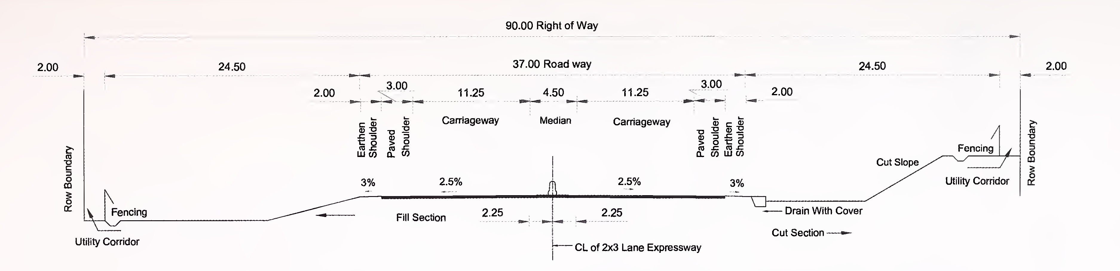
Fig. 2.2(b) Typical Cross-section For 6-Lane (2×3) Expressway in Plain or Rolling Terrain With Flush Medain
NOTE - All Dimesions are in metres
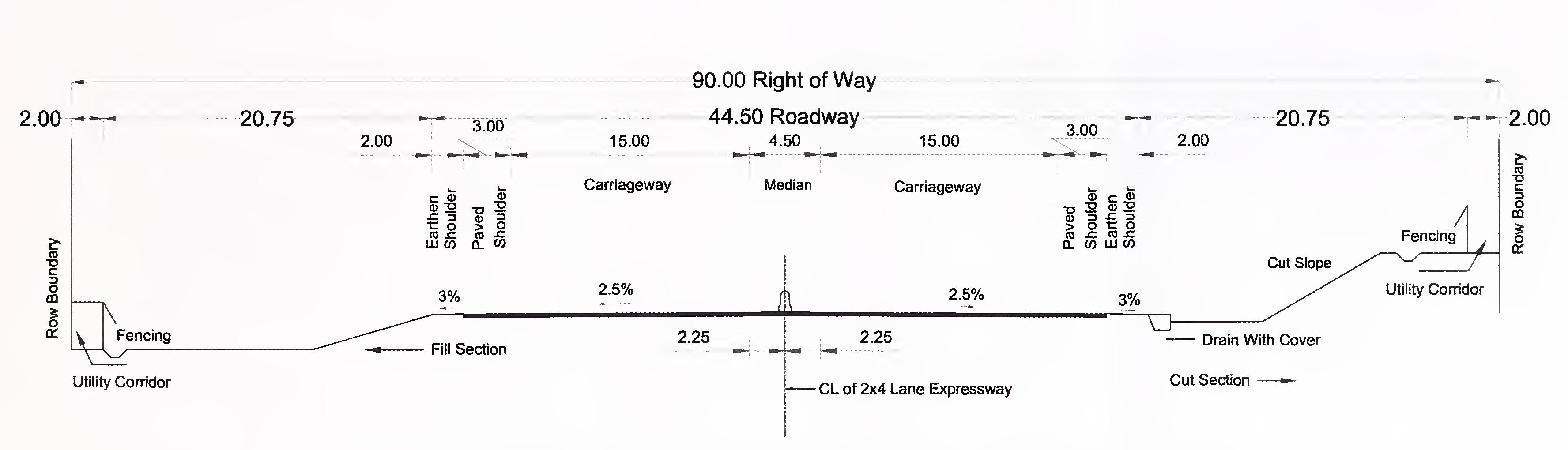
Fig. 2.2(c) Typical Cross-section For 8-Lane (2×4) Expressway in Plain or Rolling Terrain23
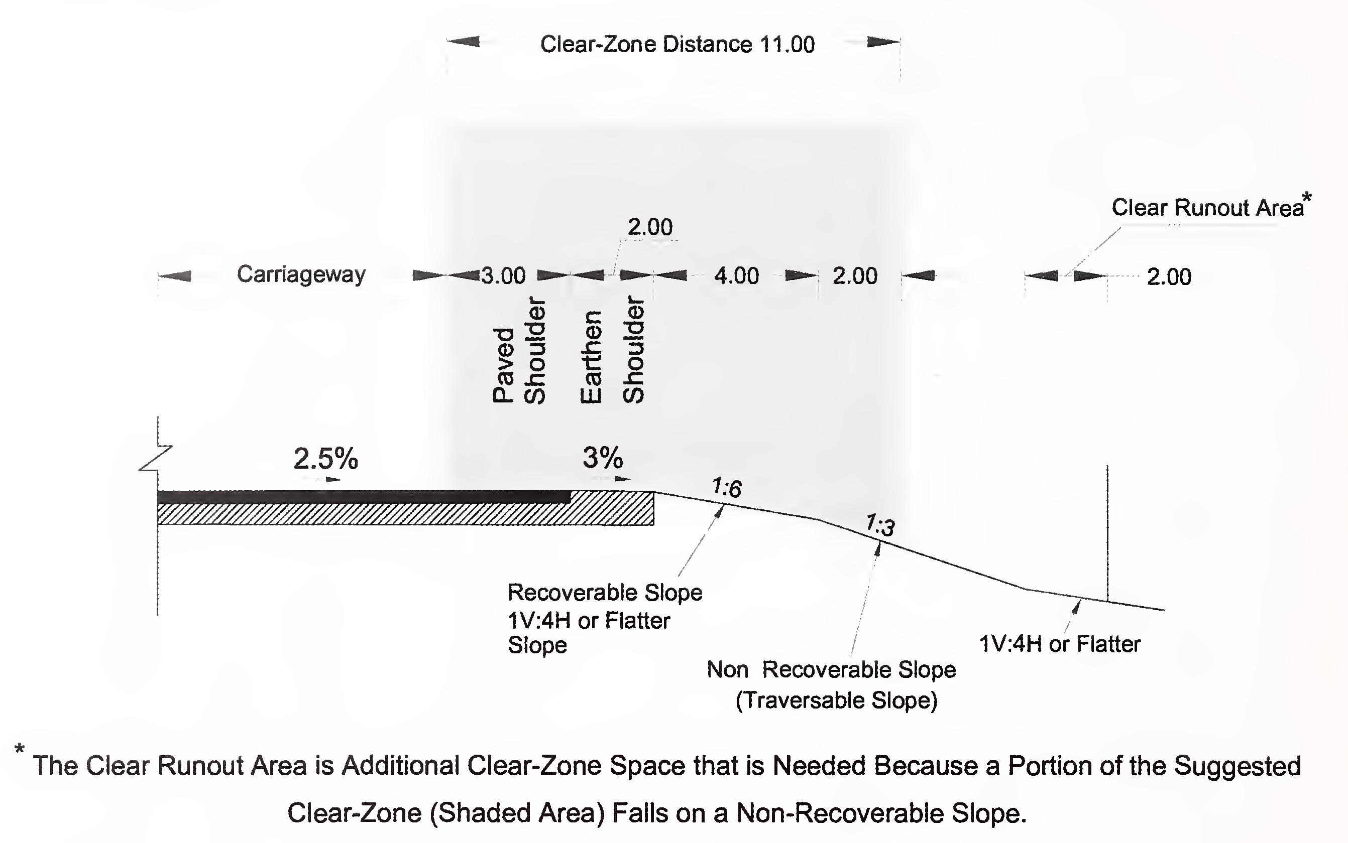
Fig 2.3 Clear Zone
NOTE - All Dimesions are in metres24
The intersections to be provided shall be one of the following types:
The types and locations of Grade Separators (Grade-separated Intersections without ramps) and Interchanges shall be based on requirements stipulated in MORTH Guidelines for Expressways. These shall be specified in Schedule-B of the Concession Agreement.
The access from the Project Expressway to the cross roads in case of Grade Separators shall be through the nearest interchange.
The geometric design standards for various elements of Grade Separators shall be as given in MORTH Guidelines for Expressways except as otherwise indicated in this Manual. Gradient for approaches shall not be steeper than 2.5 percent (1 in 40).
Design of structures shall conform to Section-6 of this Manual. Minimum length of viaduct required to be provided shall be specified in Schedule-B of the Concessionaire Agreement.
There are two broad categories of Interchanges, based on traffic exchange:
For this category, it is considered that Expressway shall be a toll road, and the other intersecting road shall be a “non-tolled” road or a road with open system of tolling with the toll plaza on the other road minimum 2 km away. This requires the consideration of tolling system which considers a barrier system as well as toll booths on the interchange ramps. This requires provision of appropriate deceleration and acceleration lanes and operating speed limitations in the interchange areas.25
For this category, since both the intersecting routes are toll roads under closed system, toll booths on ramps are not required. The system needs to cater for high speed operation. The toll collection arrangements need to be considered on integrated basis between the two involved expressway stretches. The modalities need to be suitably addressed.
Generally, Trumpet-type and T-type Interchanges are the preferred configuration. The advantages are;
Diamond and Cloverleaf Interchanges require a number of toll plazas on entry/exit ramps, whereas Trumpet-type or T-type Interchanges require single toll plaza.
System interchanges are to handle high volume of traffic. The connecting ramps can be directional, semi-directional and large radius loops as well. The aspect of toll sharing between adjacent concessionaires shall be integrated. The basic forms may comprise of three legs or four legs.
For Three Leg Interchanges, the T-type configuration would require larger loops and semi directional ramps of larger radius based on traffic volumes. This may also require catering for frontage road.
For Four Leg Interchanges, the forms may be Diamond, clover leafs directional and semi directional interchanges and composite interchanges requiring combinations of straight, curved or with loops and weaving. These configurations generally require multi-level structures. Fig. 3.1 presents illustrative service and system interchanges.
Ramps are provided at interchanges for desired turning movements. Based on movement requirements, the connecting ramps may be classified as Direct, Semi-direct and Loop ramps (Fig. 3.2).
Interchange spacing is based upon demand for access from the important cross roads, adequate distance to provide for signing and weaving and permit sufficient lengths of speed change lanes for respective adjacent interchange to operate safely and efficiently26
at a desired level of service. For expressways, a spacing of 3 km is absolute minimum from deceleration, weaving and acceleration consideration. For spacing less than 3 km, both the interchange shall be considered as a combined one. For expressways, a spacing of 20-30 km is desirable.
Recommended design speeds for interchange ramps are given in Table 3.1.
| Configuration | Type of Ramp | Range of Expressway Design Speeds (km/h) | |
|---|---|---|---|
| 100-120 | 80-100 | ||
| Range of Ramp Design Speeds | |||
| System Interchange | Semi-Direct | 50-70 | 40-60 |
| Loop | 70-90 | 60-80 | |
| Direct | 80-100 | 70-90 | |
| Service Interchange | Semi-Direct | 40-60 | 40-60 |
| Loop | 60-80 | 60-70 | |
| Direct | 60-90 | 60-80 | |
The ramp shall have two lanes. The ramp cross-section showing carriageway width and shoulder (both paved and earthen) is given in Fig. 3.3 for two way two lane ramps on tangent alignment. The width of paved and earthen shoulders considered here are for interchange ramp design only. Applicable extra wide carriageway shall be provided, as needed from ramp radius consideration.
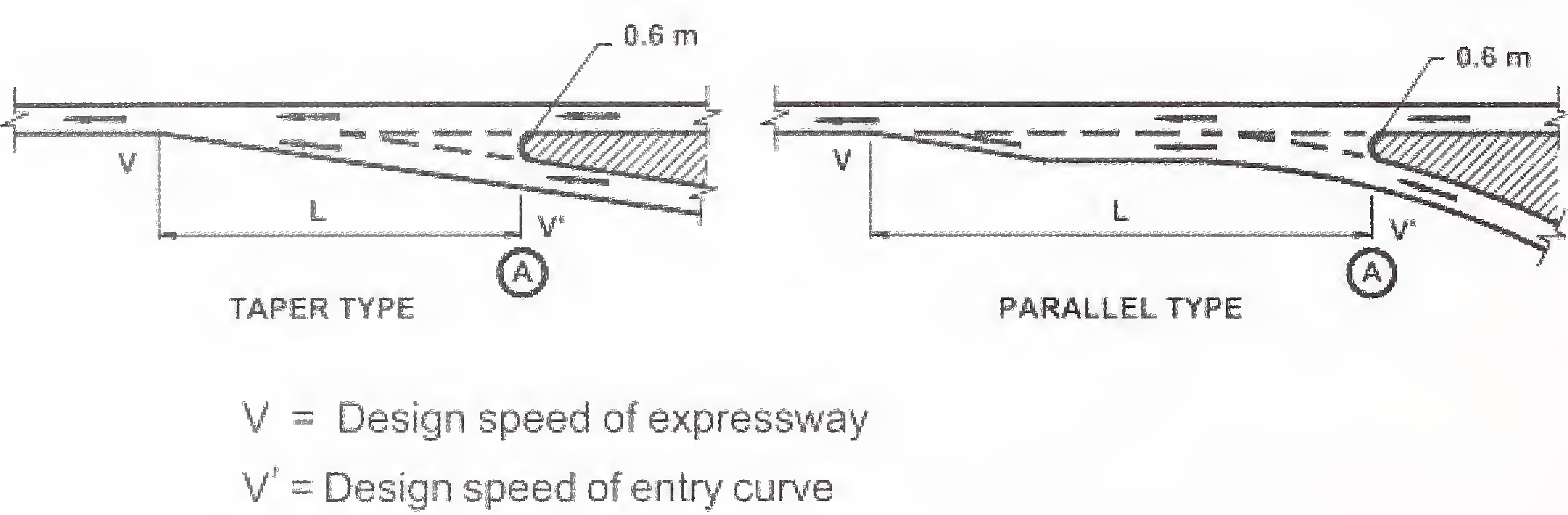
Each entry and exit ramp shall have acceleration/deceleration lane for the Project Expressway. The length of the acceleration/deceleration lanes shall be decided on the basis of speed differentials of the Project Expressway traffic and the speed permitted on the ramps.
Drivers exiting an interchange are required to reduce speed to meet with toll payment where such a scheme exists. Drivers entering an expressway from a ramp accelerate until the adjacent through lane speed is reached.
For safety, expressway exits should be located on tangent sections, wherever possible to provide maximum sight distance and optimum traffic manoeuverability operation. The following recommendations should be considered from safety aspect.
Typical requirements of Acceleration length and Deceleration length and speed change length adjustment factors are presented in Table 3.2 and Table 3.3. For flat grade exceeding 2 percent, adjustment factors given in MORTH Guidelines for Expressways shall apply.27
| Expressway Design Speed V (km/h) | Acceleration Length L (m) | ||||
|---|---|---|---|---|---|
| V’ Speed on Entry Curve at A (km/h) | |||||
| 40 | 50 | 60 | 70 | 80 or more | |
| 80 | 145 | 115 | 65 | - | - |
| 100 | 285 | 255 | 205 | 110 | 40 |
| 120 | 490 | 460 | 410 | 325 | 245 |
| Expressway Design Speed V (km/h) | Deceleration Length L (m) | ||||
|---|---|---|---|---|---|
| V’ Speed on Exit Curve at A (km/h) | |||||
| 40 | 50 | 60 | 70 | 80 or more | |
| 80 | 100 | 90 | 80 | 55 | - |
| 100 | 145 | 135 | 120 | 100 | 85 |
| 120 | 175 | 170 | 155 | 140 | 120 |
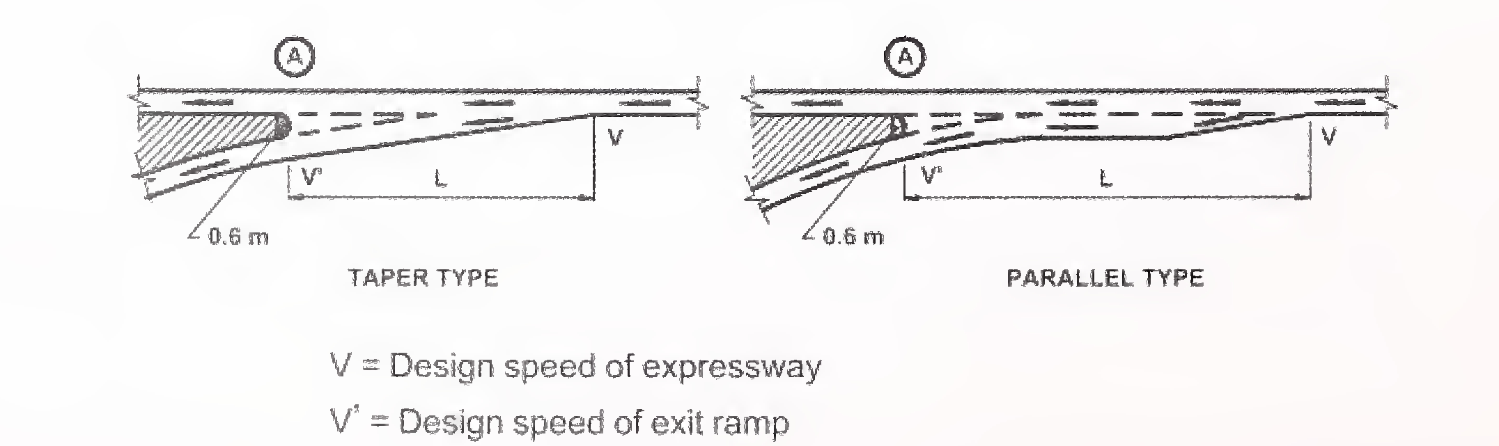
Note: For parallel type, a taper rate may be 8:1 for design speed up to 50 km/h and 15:1 for design speed of 80 km/h. For intermediate values of design speed, suitable rate of taper be adopted.28
The Concessionaire shall submit the details of the ground surveys, traffic data, traffic forecast, design and drawings of the intersections and interchanges showing all safety features to the Independent Engineer for review and comments, if any.
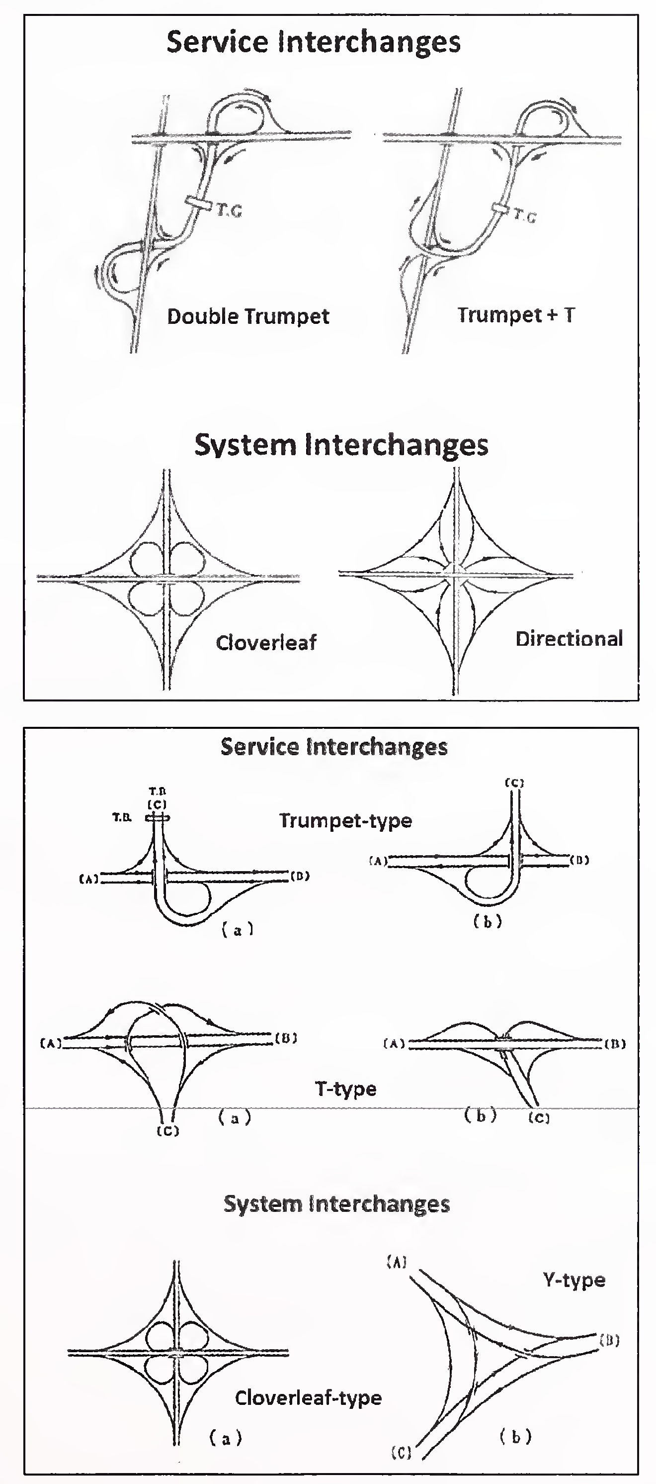
Fig. 3.1 Service and System Interchanges29
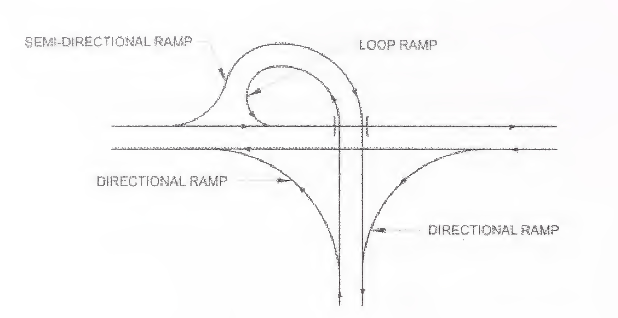
Fig. 3.2 Different Types of Ramps
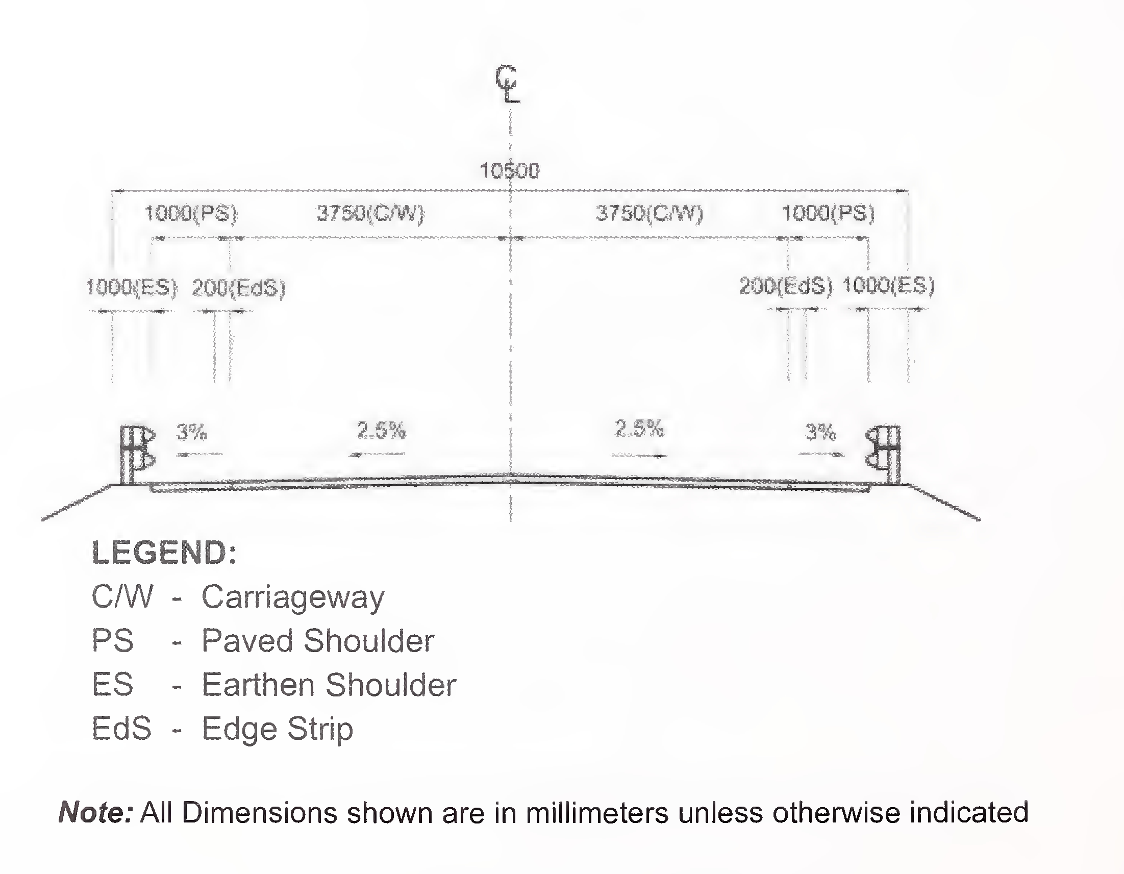
Fig. 3.3 Ramp Cross-Section30
The design and construction of the road in embankment and in cutting shall be carried out in accordance with Section 300 of MORTH Specifications and the requirements, and standards and specifications given in this Section. This Section also covers specifications for subgrade and earthen shoulders.
The final centre line of the road and the road levels shall be fixed duly considering all the relevant factors covering structural soundness, safety and functional requirements as per relevant IRC Codes and provisions of this Manual.
In plain terrain, the level of the expressway will generally be controlled by drainage and earthwork considerations and can be constructed near ground level where no flooding is reported/observed and the Water Table is not high. In rolling terrain where fill material is available from cuttings, the embankment could be sufficiently raised to permit construction of underpasses without lowering the level of cross roads. The principles given in para 4.2 below shall be followed for fixing the height of the embankment.
The height of the embankment shall be measured with respect to the finished road levels. The following principles shall be kept in view while fixing the road level:
To attain a natural appearance along the roadside, the side slopes should be as flat as possible and rounded. The slopes should be designed from stability considerations and to provide a reasonable opportunity for a driver to recover control of an errant vehicle. If the right of way or other constraints make it impractical to provide recoverable slopes, it would be necessary to provide a safety barrier. Embankment slopes 1V:4H or flatter are recoverable slopes. Fixed obstacles such as culvert headwalls shall not extend above the fill slope within the clear zone distance. Embankment slopes between 1V:3H and 1 V:4H are traversable but non-recoverable and a clear run-out area at the base is desirable as shown in Fig. 2.3.31
Embankment with height 6.0 m or above shall be designed in accordance with IRC:75 taking into account slope stability, bearing capacity, consolidation, settlement and safety considerations based on geotechnical and investigation data. Where the embankment is to be supported on a weak stratum, appropriate remedial/ground improvement measures shall be taken.
The side slopes shall be protected against erosion by providing a suitable vegetative cover, kerb and channel, chute, stone/cement concrete block pitching or any other suitable protection measures depending on the height of the embankment and susceptibility of soil to erosion. Drainage arrangement shall be provided as per Section-6 of this Manual.
Where pond ash is used for embankment construction in pursuance of the instructions of the Ministry of Environment and Forests or otherwise, the embankment shall be designed and constructed in accordance with IRC:SP:58.
The road level shall be fixed, keeping in view the provisions of relevant IRC Codes, and the side slopes of the cut section shall be governed by the type of soil met with. Generally, the side slopes shall be as given in Table 4.1. The slopes should be evaluated with regard to soil stability and potential crash severity. Desirably, the toe of the rock-cut slope should be located beyond the minimum lateral distance from the edge of the carriageway needed by the driver of an errant vehicle to either regain control or to slow down the vehicle.
| Type of Soil | Slope (H:V) |
|---|---|
| 1) Ordinary Soil | 3:1 to 2:1 |
| 2) Rock | 1/2:1 to 1/8:1 (depending upon quality of rock) |
The Concessionaire shall carry out necessary soil surveys, and field and laboratory investigations for selecting appropriate borrow pits, identifying and treating problematic ground locations, if any, and for finalizing structural features and design of the embankment and cut sections and establishing improved ground properties. A report on the soil investigations shall be furnished along with the design to the Independent Engineer.32
Soil investigations shall cover the following:
Soil investigations and tests shall be carried out in accordance with the requirements specified in IRC:SP:19 and information regarding depth of water table, seepage flow, presence of any weak, unstable or problematic strata.
The Concessionaire shall prepare the design report with all relevant details including the following:
The design and construction of pavement shall be carried out in accordance with the criteria, standards and specifications given in this Section. Where alternative specifications or materials are proposed to bring in innovation in design etc., provisions of para 1.10 of this Manual shall apply.
The design of pavement shall take into account all relevant factors for assuring reliable performance, surface characteristics and shall satisfy the specified minimum performance requirements.
The Concessionaire shall undertake the necessary soil, material and pavement investigations and traffic volume and axle load studies in accordance with the good industry practice for preparing detailed designs.
The materials, mixes and construction practice shall meet the requirements prescribed in the MORTH/IRC Specifications or recognised international specifications for performance specific mixes.
Where problematic conditions such as expansive soils, swamps or marshes, flooding, poor drainage, frost susceptible areas etc. are found to exist, adequate measures shall be designed and adopted to deal with such site conditions.
The Authority may require provision of specific type (flexible/rigid) of pavement depending upon specific site conditions. Such requirements shall be as specified in Schedule-B of the Concession Agreement. Unless otherwise specified in Schedule-B, the Concessionaire may adopt any type (flexible/rigid) of pavement structure for new construction.
The pavement shall be designed to ensure the specified performance for the projected traffic needs, climate and type of soils in the given area. The Concessionaire is expected to use a design procedure that is appropriate to produce a cost-effective structure meeting the performance requirements and long term durability. The Concessionaire may use IRC:37 “Tentative Guidelines for the Design of Flexible Pavements” or it may use any internationally accepted design procedure that is based on past performance and research. It will be the Concessionaire’s responsibility to provide a pavement structure that fully meets the prescribed performance requirements throughout the operation period.35
Jointed rigid pavement shall be designed in accordance with the method prescribed in IRC:58 “Guidelines for the Design of Plain Jointed Rigid Pavements for Highways”.
Continuously Reinforced Concrete Pavements (CRCP) shall be designed as per any recognised international guidelines which shall be subject to approval by the Independent Engineer.
The design traffic shall be estimated in terms of cumulative number of standard axles (8160 kg) to be carried by the pavement during the design period.
Estimate of the initial daily average traffic flow shall be based on determination of diverted traffic, induced and development traffic.
Any likely change in traffic due to future development plans, land use, shall be duly considered in estimating the design traffic.
Traffic growth rate shall be estimated for each category of commercial vehicles to be considered for design of pavement. For traffic projections, the procedure outlined in IRC: 108 may be followed. The Concessionaire shall adopt a realistic value of the rate of traffic growth, provided that annual rate of growth of commercial vehicles shall not be adopted less than 5 percent.
Where strengthening of pavement is needed, a detailed pavement condition survey and evaluation shall be carried out to determine
Necessary corrective measures to treat the identified deficiency shall be taken with strengthening of the pavement.
In stretches where the pavement is damaged/deteriorated to such an extent that the use of FWD method may not result in a realistic assessment of the strengthening treatment, pavement shall be designed as new pavement.38
No granular layer shall be provided over an existing bituminous surfacing.
The thickness and composition of the paved shoulder and edge strip shall be same as that of the main carriageway.
The Concessionaire shall prepare a design report and submit it to the Independent Engineer for review and comments. The pavement design proposals formulated based on the detailed investigations as required as per the relevant design Manual/Guidelines shall be submitted39
with the following details,and other additional details specific to the type of pavement proposed.
and serviceability shall be implemented in design, construction and maintenance.
Width of the culverts, bridges and grade separated structures shall be adopted as below:
Cross-sections of the pipe culverts for a 4/6/8 lane expressway are given in Figs. 6.1a, 6.1b and 6.1c respectively for depressed median and in Figs. 6.2a, 6.2b and 6.2c respectively for flush type median on approaches.
Cross section of the slab and box type culverts for a 4/6/8 lane expressway are given in Fig. 6.3a, 6.3b, 6.3c respectively for depressed median and in Figs. 6.4a, 6.4b and 6.4c respectively for flush type median on approaches.
The overall width of structures shall be such that the outer face of left crash barrier on the structure is in line with outer edge of earthen shoulder and inside crash barrier is located at a clear distance of 0.75 from the edge of outermost carriageway of adjoining road (the paved edge strip of 0.75 m on median side shall continue on the structure also).
Cross section of bridges and grade separated structures for a 4/6/8-lane expressway for one side are given in Figs. 6.5a, 6.5b and 6.5c respectively. These are applicable both for depressed median and flush type median on42
the approaches.
The Concessionaire may choose any type of structure and structure system commensurate with safety, serviceability and durability requirements. The general guidelines as below shall be followed:
The Concessionaire shall be responsible for the safe, workable design and methodology for all temporary or permanent forms, staging and centering required for supporting and forming the concrete of shape, dimensions and surface finish as shown on the drawings (Refer IRC:87). Adequate foundation for the staging shall be ensured. Redundancy in support system shall also be ensured by providing diagonals and additional members.
The following guidelines shall be adopted:
the concrete. Requirements given under Clause 3.5 of IRC:87 shall also be complied with.
Designs, drawings and methodology proposed by the Concessionaire in the use of special temporary and enabling works like Launching Girders, Cantilever Construction Equipment, Tall Formwork, Shoring for Earth Retention, Lifting and Handling Equipments and the like shall be submitted to the Independent Engineer (IE) for his review and comments, if any. The Concessionaire shall be fully responsible for the design and structural adequacy of all temporary and enabling works. Review by the IE shall not relieve the Concessionaire of this responsibility
Approach slabs shall be provided for all bridges and grade separated structures as per Clause 217 of IRC:6 and Section 2700 of MORTH Specifications.
All bearings shall be easily accessible for inspection, maintenance and replacement. Suitable permanent arrangements shall be made for inspection of bearings from bridge deck. Design and specifications of bearings shall be as per IRC:83 (Part I, II and III). Spherical bearings shall conform to the requirements of BS:5400 and materials of such bearings may conform to the relevant BIS codes nearest to the specifications given in BS:5400. The drawing of bearings shall include the layout plan showing exact location on top of pier and abutment cap and the type of bearings i.e. fixed/free/rotational at each location along with notes for44
proper installation. The bearing should cater for rotation and movement in both longitudinal and lateral direction.
The Concessionaire shall procure bearings only from the manufacturers approved by the MORTH.
The Concessionaire shall submit detailed specifications, designs and drawings including installation drawings and maintenance manual incorporating the replacement procedure for review of the Independent Engineer. The bearings shall be of such type which do not require replacement for at least 50 years for major bridges, vehicular underpasses and rail road structures and 25 years for other structures.
The Concessionaire shall obtain and submit a complete Quality Assurance Programme (QAP) from the manufacturer. The QAP shall give the full details of the process of quality control, raw material testing, various stages of manufacture, testing of bearing components as well as testing of complete bearing in conformity with relevant part of IRC:83, prior to the commencement of manufacture of the bearings.
In addition to the routine testing of the materials and bearings at the manufacturer’s premises, the Concessionaire shall arrange testing of random samples of one percent (minimum one number of each type) of bearings from independent agency approved by the IE.
The Concessionaire shall submit a certificate of confirmation regarding quality control measures taken during manufacture of the bearings and the material conforming to the prescribed standards and specifications. Full lot of bearings of the sample found to have inferior specifications to those certified by the manufacturer or to have major discrepancy in material specifications or which fail to meet the acceptance criteria, shall be rejected.
The design and construction of reinforced earth structures shall conform to section 3100 of MORTH Specifications. Reinforced earth retaining structures shall not be provided near water bodies. Such structures should be given special attention in design, construction, ground improvement where necessary, maintenance and selection of System/System design. Local and global stability of the structure shall be ensured.
Design Accreditation and warranty for life of the structure from the approved supplier/manufacturer shall be obtained and furnished. A qualified and experienced technical representative of the approved supplier/manufacturer shall be present on site throughout during the casting and erection phases to ensure that the quality of the works executed by the Concessionaire is in accordance with good industry practice.
The packaging of reinforcing elements shall clearly indicate the name of the manufacturer/supplier and brand name, date of production, expiry, if any and batch identification number along with the manufacturer’s test certificates.
An effective drainage system for the bridge deck shall be planned, designed and installed so as to ensure that water from the deck is taken down to ground level/drainage courses by adequate size of drainage spouts and pipes. Guidelines for drainage given in Section-9 of this Manual shall be adopted.
and Vehicle crash barrier type shall be provided on all other structures. The sketches of concrete crash barriers extracted from IRC:5 are given in Figs. 6.6a and 6.6b for Vehicular Crash barrier and High Containment type Crash barriers respectively.
Future widening of structures shall be adopted by suitable method so that there is seamless travel path. Suitable markings and signages shall be placed for guidance of traffic. It will be better if the new structure is stitched with the existing structure by dismantling the crash barrier on the existing structure. Where stitching is not possible, new structure may be added abutting the old structure, crash barrier dismantled and longitudinal joint provided between the old and widened structure. The edge strips of the two structures may be suitably marked to prohibit vehicles travelling on this portion. Any other innovative method of widening the old structure may be adopted so that safety of structure and traffic is not compromised.
The Concessionaire shall furnish the design report, including the following, to the Independent Engineer for his review and comments, if any.
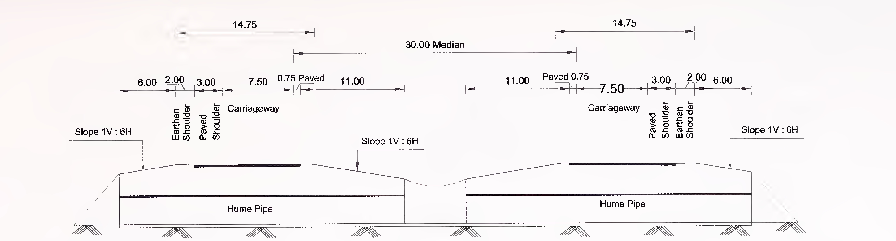
Fig. 6.1 (a) Typical Cross-section of Pipe Culvert for 4-Lane (2×2) Expressway with Depressed Median
NOTE - All Dimension are in metres
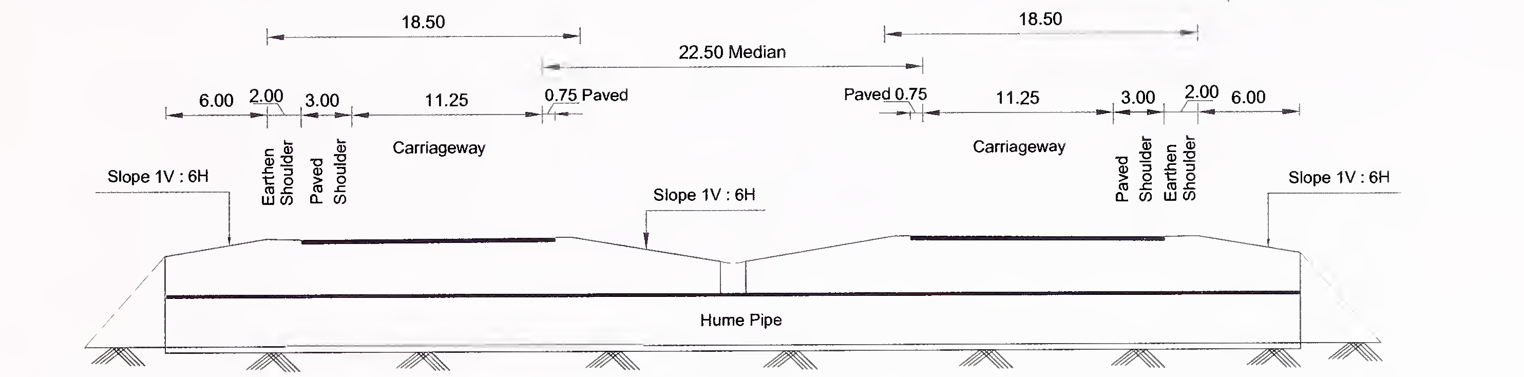
Fig. 6.1 (b) Typical Cross-section of Pipe Culvert for 6-Lane (2×3) Expressway with Depressed Median
NOTE - All Dimension are in metres
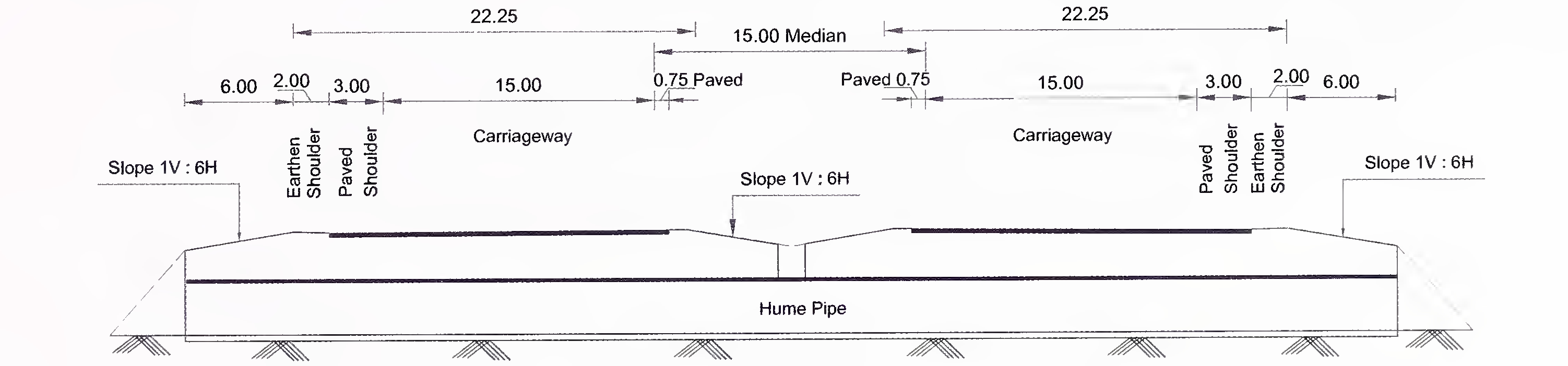
Fig. 6.1 (c) Typical Cross-section of Pipe Culvert for 8-Lane (2×4) Expressway with Depressed Median
NOTE - All Dimension are in metres49
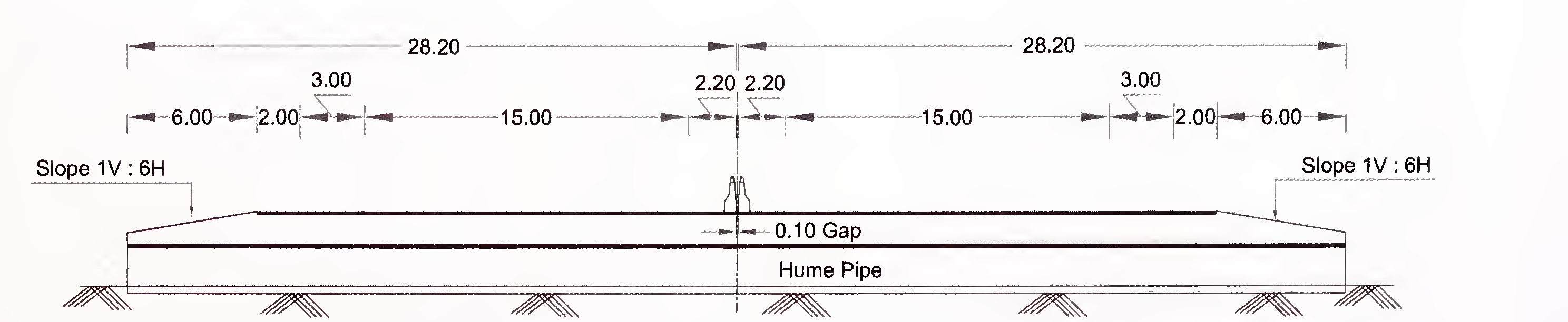
Fig. 6.2 (a) Typical Cross-section of Pipe Culvert for 4-Lane (2×2) Expressway with Flush Median
NOTE - All Dimension are in metres
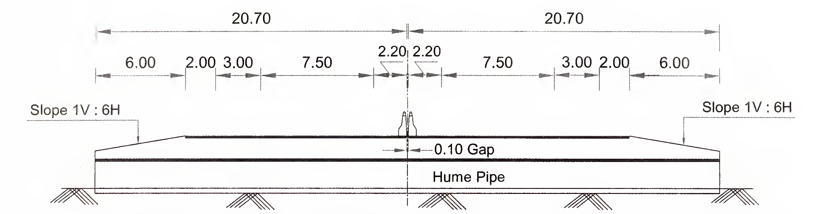
Fig. 6.2 (b) Typical Cross-section of Pipe Culvert for 6-Lane (2×3) Expressway with Flush Median
NOTE - All Dimension are in metres
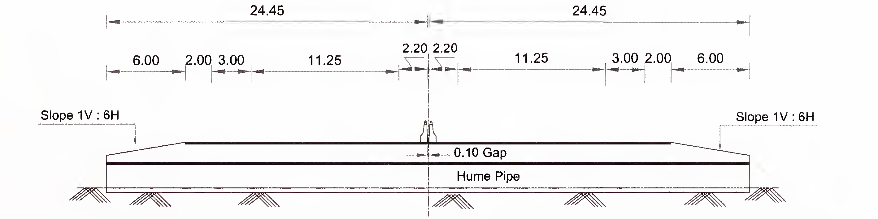
Fig. 6.2 (c) Typical Cross-section of Pipe Culvert for 8-Lane (2×4) Expressway with Flush Median
NOTE - All Dimension are in metres50
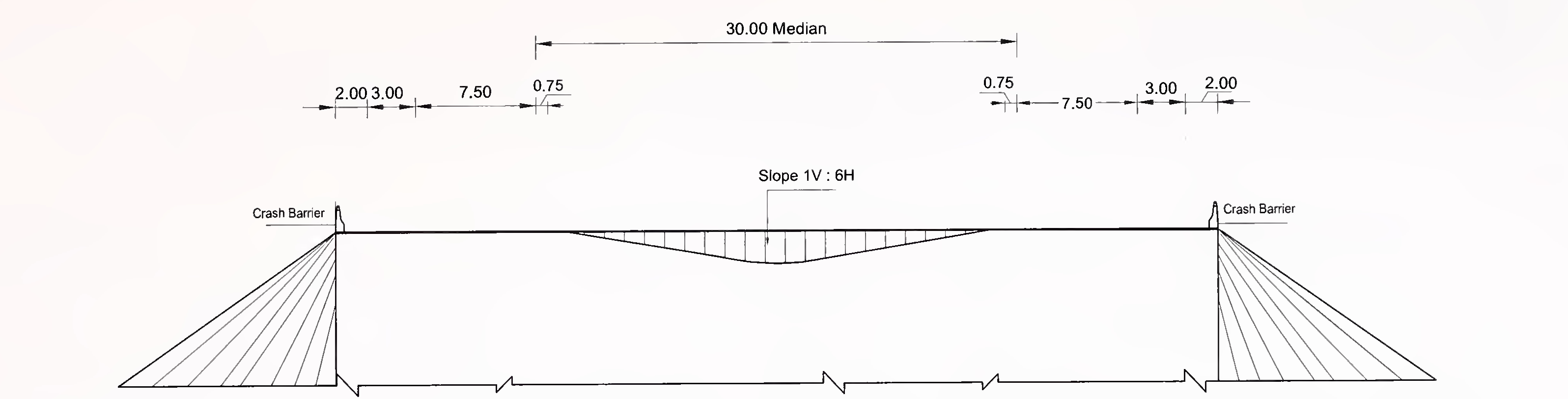
Fig. 6.3 (a) Typical Cross-section of Slab and Box Type Culvert for 4-Lane(2×2) Expressway with Depressed Median
NOTE - All Dimension are in metres
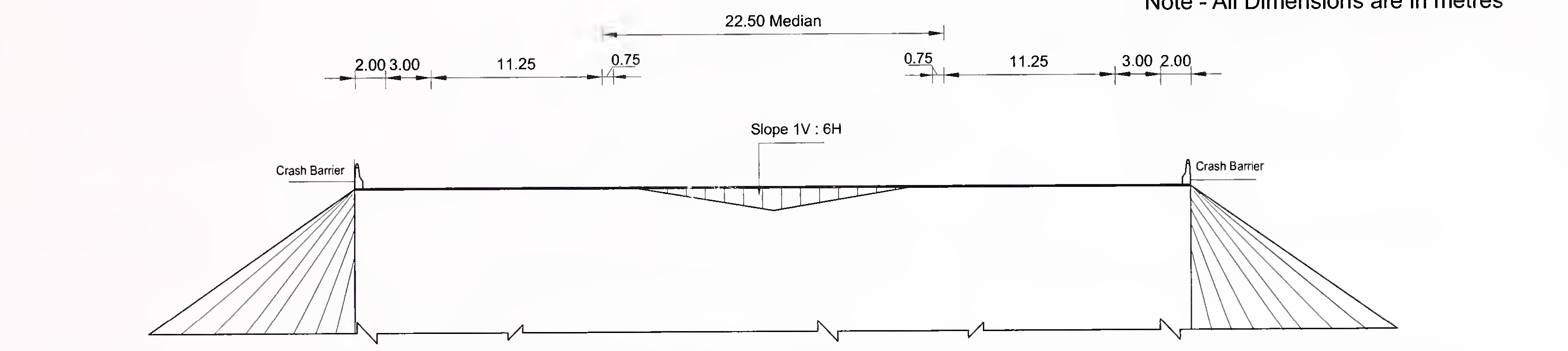
Fig. 6.3 (b) Typical Cross-section of Slab and Box Type Culvert for 6-Lane(2×3) Expressway with Depressed Median
NOTE - All Dimension are in metres
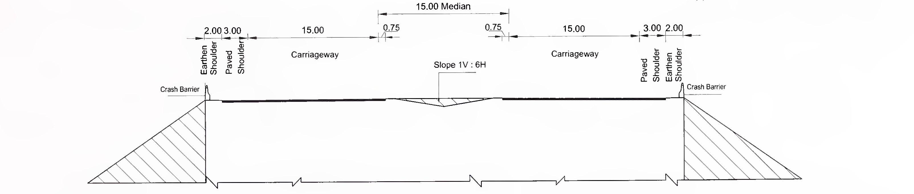
Fig. 6.3 (c) Typical Cross-section of Slab and Box Type Culvert for 8-Lane (2×4) Expressway with Depressed Median51
NOTE - All Dimension are in metres
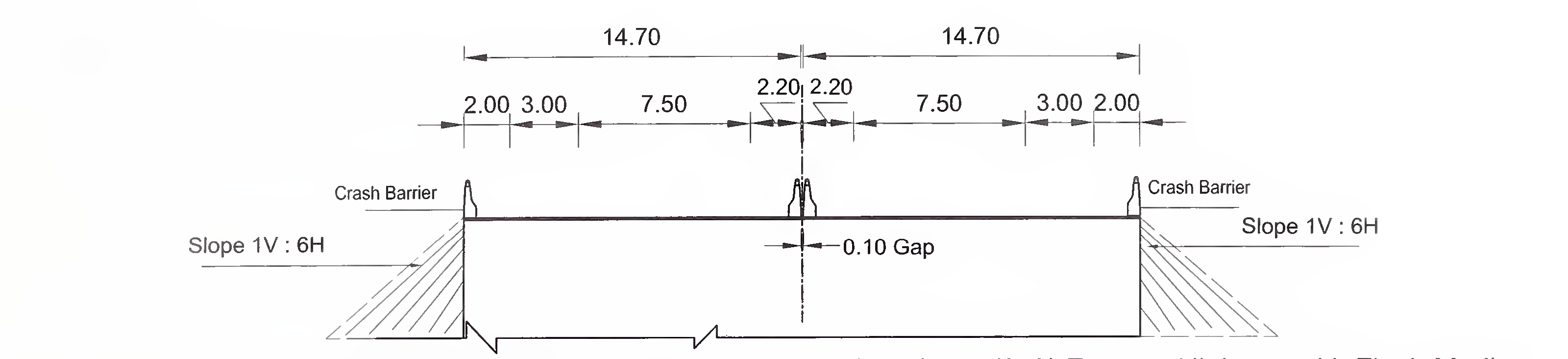
Fig. 6.4 (a) Typical Cross-section of Slab and Box Type Culvert for 4-Lane(2×2) Express Highway with Flush Median
NOTE - All Dimension are in metres
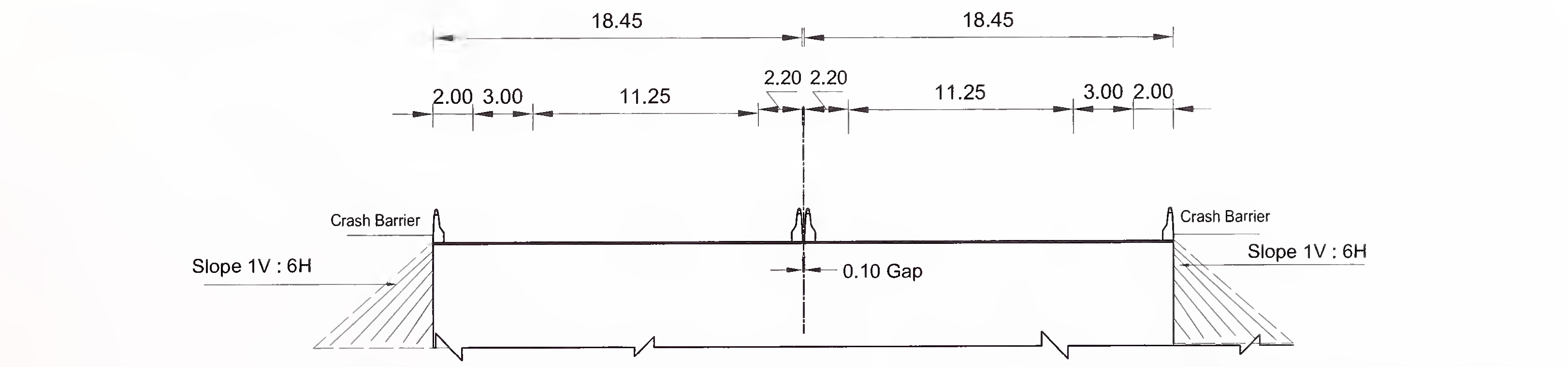
Fig. 6.4 (b) Typical Cross-section of Slab and Box Type Culvert for 6-Lane(2×3) Express Highway with Flush Median
NOTE - All Dimension are in metres

Fig. 6.4 (c) Typical Cross-section of Slab and Box Type Culvert for 8-Lane(2×4) Express Highway with Flush Median
NOTE - All Dimension are in metres52
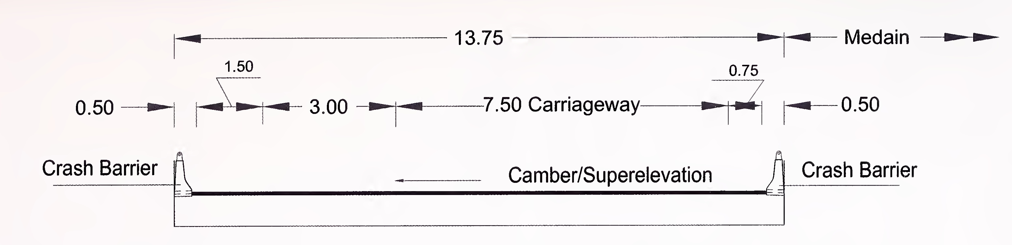
Fig. 6.5 (a) Typical Cross-section of 4-Lane (2×4 Lane) Bridge and Grade Separated Structures (One side)
NOTE - All Dimension are in metres
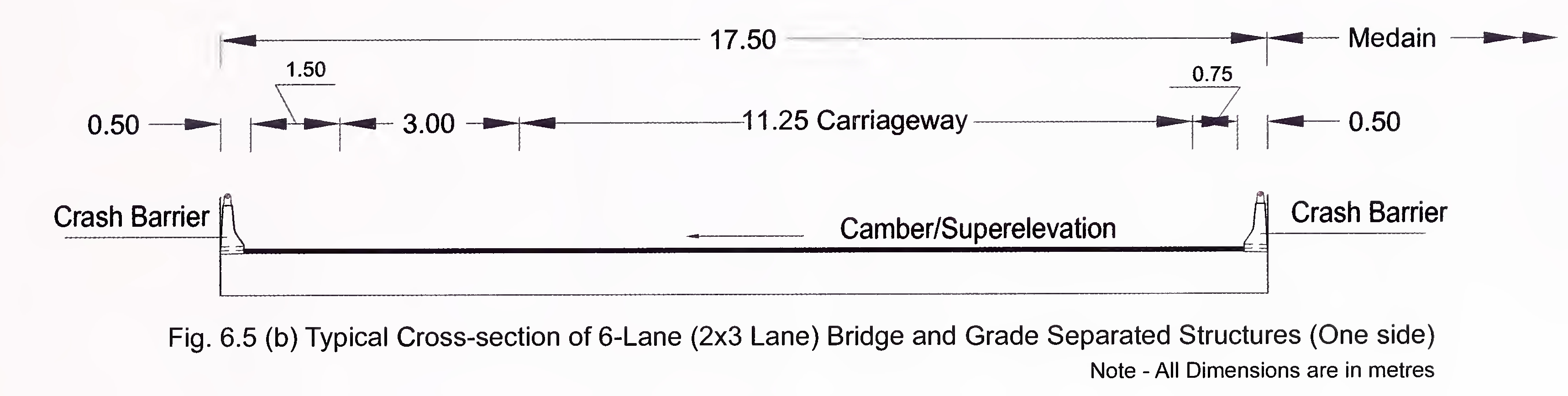
Fig. 6.5 (b) Typical Cross-section of 6-Lane (2×3 Lane) Bridge and Grade Separated Structures (One side)
NOTE - All Dimension are in metres
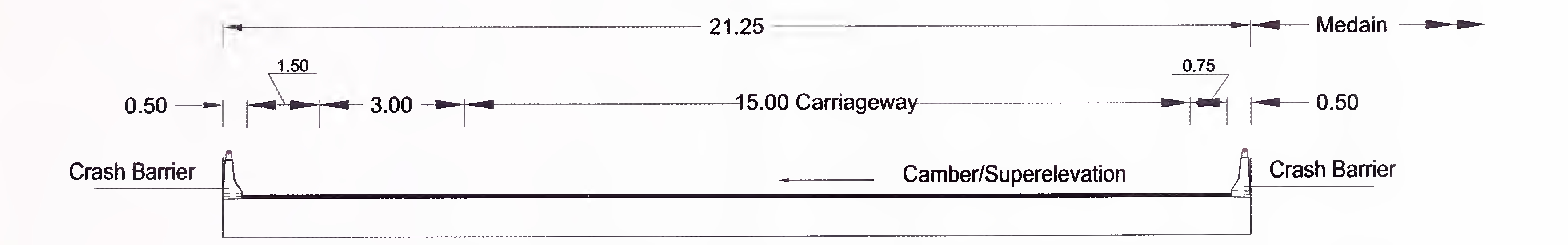
Fig. 6.5 (c) Typical Cross-section of 8-Lane (2×4 Lane) Bridge and Grade Separated Structures (One side)53
NOTE - All Dimension are in metres
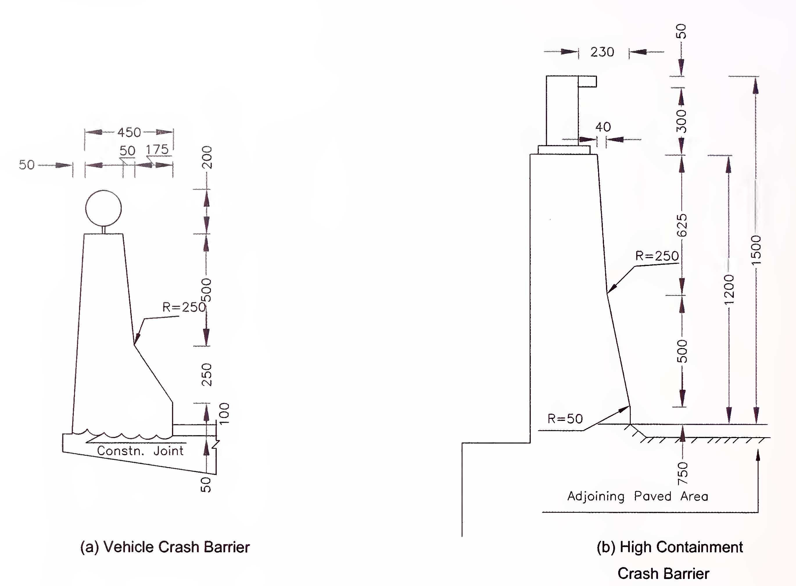
Fig. 6.6 Typical Details of Crash Barriers
(Extracts From IRC:5)54
Note - All Dimensions are in Millimetres
Expressway shall be constructed in tunnel either to carry the alignment under or through a natural obstacle or to minimize the impact on the community under conditions such as:
Planning and design of tunnel shall be based on various conditions along the expressway alignment including the topography, geology, meteorology, environment, locations and traffic volumes and shall generally conform to provisions of IRC:SP:91 and this Manual.
Wherever tunnel is required to be provided, its location, length and number of lanes shall be indicated in Schedule-B of the Concession Agreement.
A tunnel shall have the same geometric standards as on the expressway carriageway outside the tunnel except as specified in this Section.
Shape of tunnel cross section shall be commensurate with the methodology of construction, e.g., mining or cut-and-cover method, geotechnical conditions and structural consideration.
The tunnel shall cater for carriageway, paved shoulder, edge strip as on the adjoining carriageways outside the tunnel, and space to be provided for ventilation ducts, escape footway, emergency lay-bye where necessary, lighting, drainage, fire and other services.
The tunnel shall have a minimum vertical clearance of 5.5 m over the full width of carriageway and paved shoulders. Vertical clearance over footway shall be 3.0 m minimum. Additional vertical clearance shall be provided for accommodating tunnel ventilation and lighting fixtures.55
For Project Expressways up to 8-lanes, twin tubes of 3-lane configuration shall be provided.
Tunnels shall have paved shoulder of 3.0 m on left side and edge strip of 0.75 m on the right side. In case of tunnels having more than 500 m length, provision shall be made for 10 m long and 1.5 m wide emergency lay bye beyond the left most lane at 750 m intervals to facilitate refuge for break down/damaged vehicles and also for maintenance vehicles. Proper transitions, line of sight and informatory signs shall be ensured for such lay-bye.
Typical tunnel cross sections for unidirectional traffic conditions for three-lane carriageway configurations are given in Fig. 7.1 for cut and cover type construction and in Fig. 7.2 for mining type construction. A typical layout of lay-bye is shown in Fig. 7.3 for tunnels of length more than 500 m.
The clear distance between the twin tubes shall be kept depending upon the type of strata and structural stability of the tunnel. Guidance in this regard may be taken from IRC: SP: 91 or any specialist literature.
The twin tunnels of more than 500 m length shall be connected by a cross passage at an inclination to facilitate diversion of the traffic from one tube to other tube in the event of an incident/accident in one of the tubes at a spacing of 300 m. The cross passage shall be at an angle of 30 degrees with the direction of flow as shown in Fig. 7.4. The cross passage shall have provision for one traffic lane, edge strip of 0.75 m, crash barriers and walkways on either side. In normal conditions, the cross passage shall be barricaded.
The vertical gradient shall not be more than 3 percent for tunnels of length more than 500 m. In short tunnels, the gradient may be limited to 6 percent. However, in such cases the ventilation system should be designed to take effect of gradient and possible incidence of fire.
The horizontal alignment shall be straight as far as practicable. However, the straight stretch shall not be more than 1500 m to avoid the effect of monotony and induction of an unconscious increase in speed. Similarly, the last few metres of the tunnel shall have gentle curve. The curves, if provided, shall be gentle and meet the minimum radius requirements for design speed of the tunnel. Tunnel alignment at the ends and open/approach cuts shall merge smoothly with adjoining road in the open air. In case of twin tunnel, the crossing of56
central median shall be provided at suitable locations at approaches of both tunnel tubes so as to allow emergency services gain immediate access to either tube and also to send back diverted traffic to proper traffic lanes.
Tunnel approach shall have smoothly aligned tunnel walls without any sudden narrowing to avoid a shift from the tunnel wall and a good day/night visibility of the edge lines. Tunnel wall lining shall be of white colour with high luminous reflectance.
Tunnel portals should, apart from providing protection at entry and exit, convey drivers about the presence of the tunnel, reduce the luminance of facing walls and be in harmony with the surrounding environment from aesthetics considerations.
In order to make a realistic geotechnical and geophysical assessment of the ground through which the tunnel is to pass and detailed mapping of surface geology of the tunnel area necessary for the planning and design of alignment and portal locations, shape of tunnel, tunnel supporting systems, minimum distance to be kept between two tunnels, independent geotechnical investigations should be carried in accordance with the provisions of Section-3 of IRC:SP:91.
Assessment of applicable loads shall be based on structural properties of the ground likely to be met during tunneling as arrived from detailed geo-technical investigations.
The design shall cater to the most adverse combination of load conditions including only those loads which have reasonable probability of simultaneous occurring with due consideration for the methodology of construction particularly in case of soft strata and soils. The design shall be checked for loading conditions during the stages of construction, operation and maintenance.
Provisions of Section-4 of IRC:SP:91 shall be followed for the structural design of tunnels passing through rock.
Structural design of tunnel system passing through soft strata and soils may be carried out by suitable national or international standards, specialist literature and best engineering practices.57
Efficient and effective drainage system shall be provided in the tunnel for the removal of water from rainfall, seepage, tunnel washing operations, vehicle drippings/spillage on fire fighting operations.
In order to trap rainwater from hill slopes and prevent it from flowing into the approach cuts and the tunnel, suitable catch water drains shall be provided above the top of sides of the open/approach cuts and above excavated portals.
In the open/approach cuts discontinuous kerbs shall be provided to demarcate the edge of the carriageway. Beyond the kerbs, side drains with adequate waterway shall be provided in the open/approach cuts.
Inside the tunnel, suitable side drains shall be provided behind the kerbs/crash barriers. Suitable drain pipes going through the kerbs/crash barriers shall be provided to lead seepage and wash water to the drains. The drains shall be located below the walkways meant for the pedestrians and maintenance personnel. The carriageway shall have suitable camber to facilitate drainage into the side drains. In case of bi-directional tunnel, the camber shall be from the centre outwards and in case of uni-directional tunnel from high speed lane towards low speed lane. The vertical profile shall facilitate self draining of tunnel. In case this is not feasible, detailed draining system shall be designed by providing sumps and combination of self draining and pumping arrangements.
The black-topped road surface inside tunnel, generally constructed on rocky subgrade, gets damaged due to seepage water and creates severe problem for surface drainage. Hence the pavement inside the tunnel and in approach cuts shall be of high performance pavement concrete.
Waterproofing in the form of tunnel lining such as cast in situ concrete shall be provided for structural protection from surrounding weathering effects as well as operational considerations. To prevent water leaks inside the tunnel, water proof sheet at least 0.8 mm thick with synthetic textile buffer between shotcrete and lining shall be provided.
Natural ventilation may be sufficient for tunnels of length up to 500 m. However for tunnels of length more than 250 m natural ventilation system should be used only after thorough evaluation of reliance on natural ventilation especially with reference to effects of meteorological and operating conditions.
Mechanical system of ventilation shall be provided in case of tunnels of length more than 500 m.
Detailed design of ventilation shall be carried out as per Section-7 of IRC:SP:91 keeping in view the length, shape, size, tunnel environs and complexion of the likely traffic for which tunnel has been designed.58
For tunnel illumination/lighting refer Section 15 of this Manual.
Provisions shall be made for installation of tunnel furnishing such as sign boards, fire fighting arrangements, cable trays for telephone and power lines etc. in consultation with relevant local authorities.
Variable messages signs inside the tunnel shall be provided for the information of traffic of lane blockage/closure due to incidents related to vehicles/non-vehicles, weather and human hazards etc. or maintenance operations as also to warn of possible hazard ahead due to any abnormal situation. Signage system shall be complemented by providing traffic lights above each lane at the entry portal end and inside. Signages indicating distance travelled, distance/direction to an exit on evacuation route shall be provided inside the tunnel.
Tunnel carriageway markings consisting of a discontinuous line separating the traffic lanes and continuous line separating the lateral traffic lane from the paved shoulder and emergency lay-bye shall have good day/night visibility and conform to IRC:35. The markings shall be done by means of self propelled machine which has a satisfactory cut-off capable of applying broken line automatically.
Tunnel emergency facilities to mitigate damage in the event of incidence of fire or any other accident in the tunnel shall be provided in conformity with the standards for installation of emergency facilities according to the classification based on traffic volume and length of tunnel as shown in Fig. 7.5 and guidelines of emergency facilities for each classification of tunnel vide Table 7.1 as per details in para 7.11.2.
Types of details of emergency facilities to be provided are categorized as Information and Alarm Equipment, Fire Extinguishing Equipment, Escape and Guidance Facilities and other equipment. Requirements are as under:
| Classification | AA | A | B | c | D | Remarks | ||
|---|---|---|---|---|---|---|---|---|
| Emergency Facilities | ||||||||
| Information alarm equipment | Emergency telephone | ⚪ | ⚪ | ⚪ | ⚪ | ⚪ | Omitted in Class D tunnels less than 200 m in Length | |
| Pushbutton type information | ⚪ | ⚪ | ⚪ | ⚪ | ||||
| Fire detector | ⚪ | ⚪ | Omitted in tunnel without ventilation system | |||||
| Emergency alarm equipment | Tunnel entrance information board | ⚪ | ⚪ | ⚪ | ⚪ | ⚪ | Can be omitted in tunnels less than 200 m in Length | |
| In-tunnel information board | ⚪ | ⚫ | To be installed in Class A tunnels 3,000 m or more in length | |||||
| fire extinguishing | Fire extinguisher | ⚪ | ⚪ | ⚪ | ⚪ | ⚪ | ||
| Fire plug | ⚪ | ⚪ | ⚫ | To be installed in Class B tunnels 1,000 m or more in length | ||||
| Escape and guidance equipment | Guide board | Emergency exit lamps | To be installed in tunnels with evacuation adits | |||||
| Guide board | To be installed in tunnels with evacuation adits | |||||||
| Emergency exit direction board | To be installed in tunnels with evacuation adits | |||||||
| Guide board | ⚪ | ⚪ | ⚪ | To be installed in tunnels without evacuation adits | ||||
| Smoke discharge equipment and Escape passage | ⚫ Evacuation adits to be provided in tunnels of around 750 m or more in length. | |||||||
| ⚫ Smoke discharge equipment to be provided in tunnels of around 1,500 m | ||||||||
| ⚫ Evacuation tunnels provide for those Class AA tunnels and Class A tunnels of a length of 3,000 m or more which empoly a two-way traffic system and a longitudinal ventilation system. | ||||||||
| ⚫ Either evacuation adits or smoke discharge to be provided for Class AA | ||||||||
| Other equipment | Hydrant | ⚪ | ⚪ | ⚫ | To be provided in Class B tunnels 1,000 m or more in length. Tunnels equipped with hydrants are to be provided with water supply ports near the entrance. |
|||
| Radio communication auxiliary equipment | Coaxial cables | ⚪ | ⚫ | To be provided in Class A tunnels 3,000 m or more in length. | ||||
| Entrance/exit telephone | ⚪ | ⚪ | ||||||
| Radio rebroadcasting equipment | interrupt function provided | ⚪ | ⚫ | To be provided in Class A tunnels 3,000 m or more in length. | ||||
| Cell phone connectivity | ⚪ | ⚪ | ⚪ | ⚪ | ⚪ | To be provided | ||
| Loudspeaker equipment | To be provided in tunnels equipped with a radio rebroadcasting equipment (with interruption function) | |||||||
| Water sprinkler system | ⚪ | ⚫ | To be provided in Class A tunnels 3,000 m or more in length, and serviced in two way traffic. | |||||
| CCTV | ⚪ | ⚫ | To be provided in Class A tunnels 3,000 m or more in length. | |||||
| Lighting equipment for power failure | To be provided in tunnels 200 m or more in length. | |||||||
| Emergency Power supply equipment | Independent power plant | To be provided in tunnels 500 m or more in length. | ||||||
| Non-failure power supply equipment | To be provided in tunnels 200 m or more in length. | |||||||
| LEGEND : | ⚪-Mandatory | ⚫ - Use with consideration60 | ||||||
It shall be ensured that all applicable rules and regulations relating to the construction of tunnels are duly complied with in strict conformity with the spirit and body of such regulations.
A project safety plan (PSP) relevant to particular site shall be prepared by the Concessionaire and got approved from the competent authority. The PSP shall address all site-specific issues and take all the identified risk elements. During all operations connected with the construction of tunnels, appropriate safety precautions shall be taken through the implementation of the PSP.
An emergency management plan shall be part of the approved Project Safety Plan which shall be well communicated to all working personnel and prominently displayed at site. Emergency Research Measures should be drawn up to take care of various possible contingencies.
Provisions of Section-6 of IRC:SP:91 shall generally be followed for safety during construction of tunnels.62
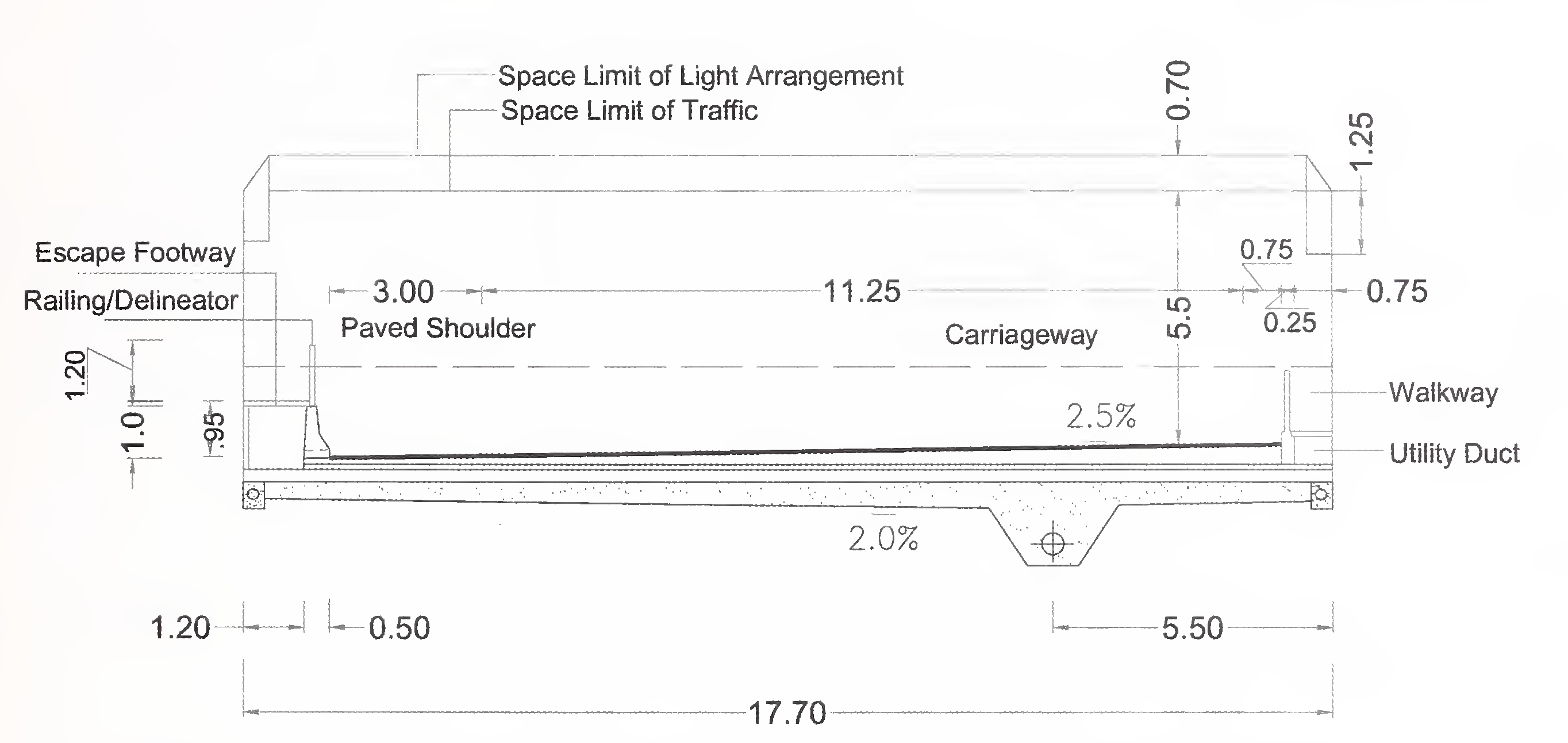
Fig. 7.1 Typical Cross-section of Three Lane Tunnel Cut and Cover Construction
NOTE - All Dimension are in metres
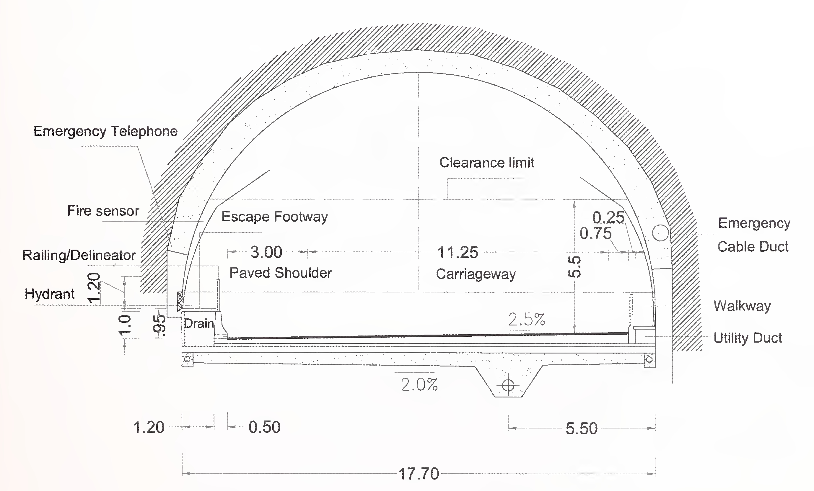
Fig. 7.2 Typical Cross-section of Three Lane Tunnel Mining Type Construction
NOTE - All Dimension are in metres
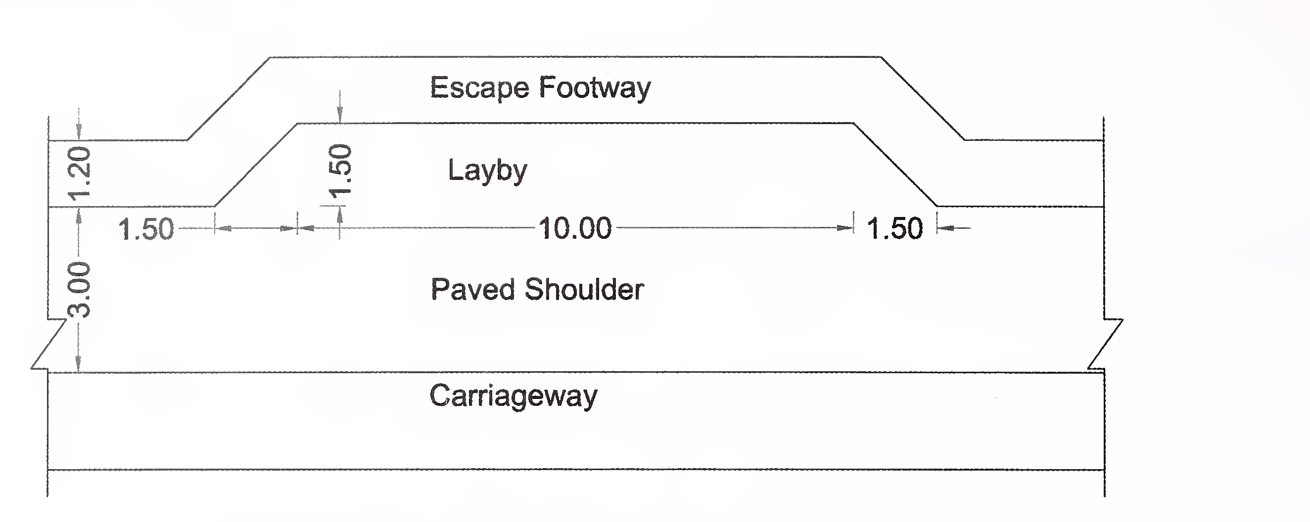
Fig. 7.3 Typical Layby Inside Tunnels Length more than 500 m
(At 750 nn Interval)
NOTE - All Dimension are in metres63
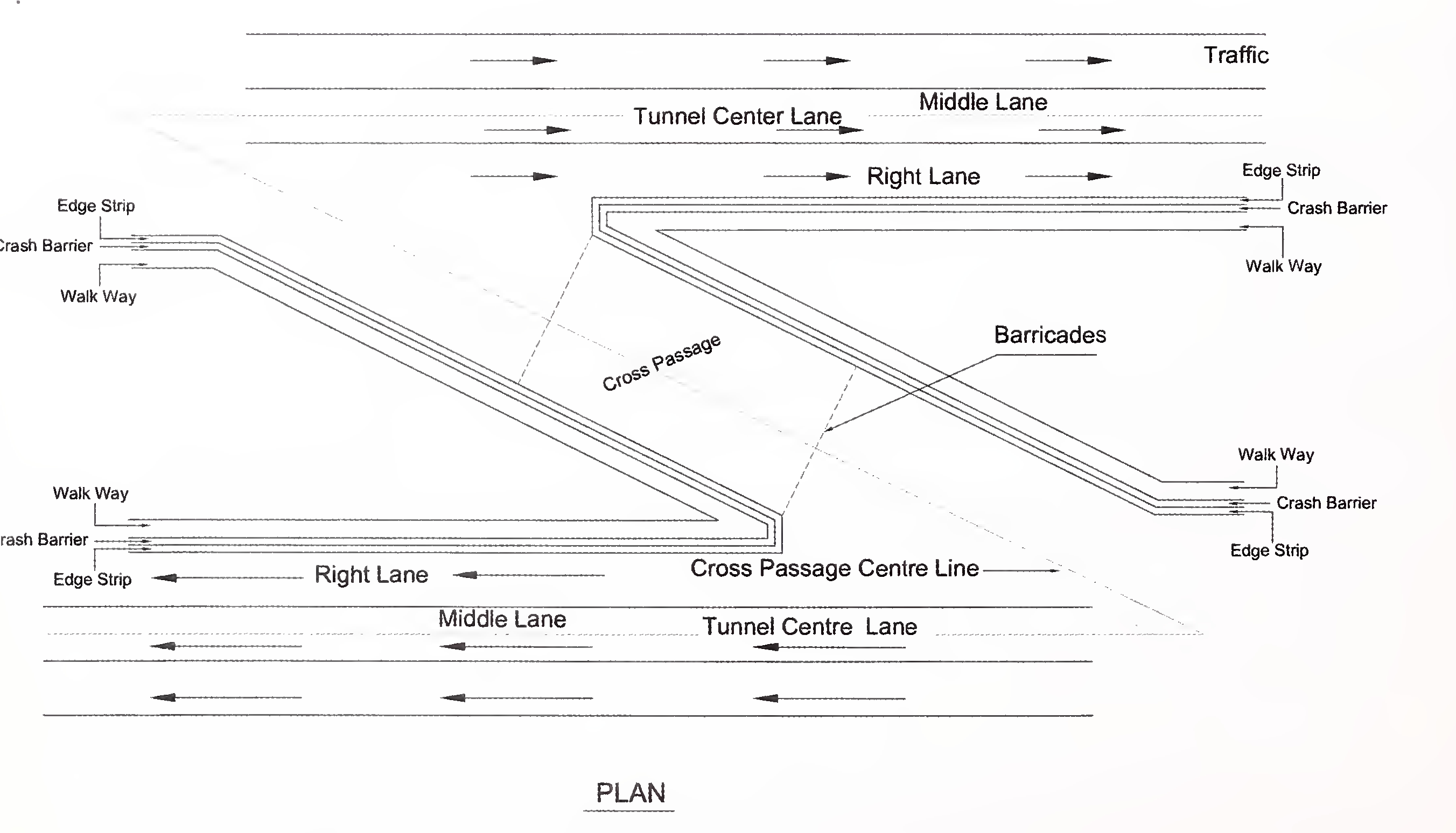
NOTE - All Dimension are in metres
Fig. 7.4 Tunnel Passage64
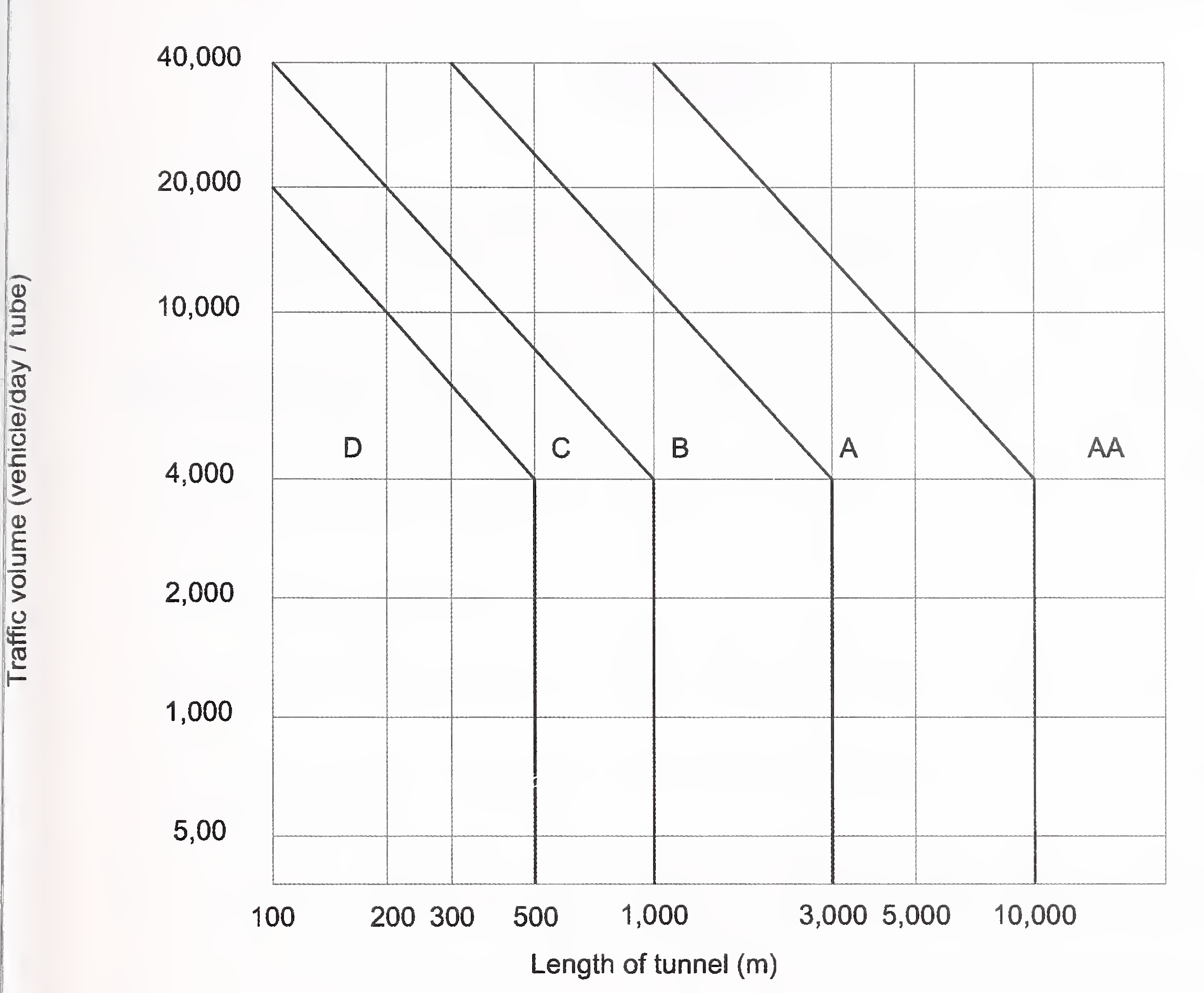
Fig. 7.5 Classification of Tunnels65
All materials to be used in works shall be in conformity with the requirements laid down for relevant item in MORTH Specifications. If the Concessionaire proposes to use any material, which is not covered in MORTH Specifications, it shall conform to IRC or relevant Indian or International Standards, provisions of para 1.10 shall apply.
Proprietary products proposed to be used shall be proven by use in comparable international road and bridge projects, and shall be supported with authenticated licensing arrangement with the manufacturer.66
The design and construction of surface and subsurface drains for road drainage and drainage for structures shall be carried out in accordance with the requirement of this Section.
For efficient drainage system for the entire Project Expressway including structures, directions contained in Clause 309 of MORTH Specifications, IRC:SP:42, IRC:SP:50 and IRC:SP:90 as relevant shall be followed.
In road sections in cuttings and at underpasses where it may not be possible to drain out the water using gravity flow, vertical drains may be provided and if necessary, arrangement for pumping shall also be made.
The selection of type of roadside drains shall be based on the magnitude and duration of flow. The roadside drains shall be designed on the principles of flow in open channel.
The road side drains shall not pose any danger to traffic, slopes of cuttings, embankment, pavement or structures.
As far as possible, longitudinal slope shall not be less than 0.5 percent for lined drains and 1.0 percent for unlined drains. Permissible non-erodible flow velocity for corresponding earth surface as mentioned in Clause 9.4 of IRC:SP:42 shall be kept in view
The side slopes of the unlined drains shall be as flat as possible and shall not be steeper than 2H:1V.
The drains shall be provided with CC lining in the following situations:
In case of depressed median, longitudinal drain (lined or unlined) shall be provided to drain off rain water. The drain should have adequate longitudinal slope to the nearest culvert to drain off transversely. In superelevated sections, the longitudinal drain shall be designed to take the discharge from one side carriageway also.
The flush median shall be paved and provided with camber for drainage across the pavement. In superelevated sections, combination of covered longitudinal and cross drains shall be provided.67
In embankments with height more than 6 m and approaches to bridges, special arrangement for protection of embankment slopes shall be essential in order to ensure that embankment slopes maintain their shape during the monsoon season. In this respect, directions contained in Clause 7 of IRC:SP:42 may be followed as appropriate for the climatic conditions of the area of the Project Expressway.
Drainage arrangement shall include provision of kerb channel outside the paved shoulder, cement concrete lined chutes along the slopes at designed intervals with energy dissipation basin, side channels at the bottom and protection of the slope by turfing, vegetation and/or any other suitable type. The drainage system and slope protection shall be kept well maintained at all times.
The chute drains and drains at toe of the embankment shall be of Plain Cement Concrete (M15 grade), over bedding in Cement Concrete M10.
Suitable catch water drains shall be provided on the hill slope above cutting to collect and remove surface water run-off from upper reaches. These drains shall be of trapezoidal shape with stone lining pointed with cement sand mortar.
The catch water drains shall be designed to carry the intercepted water to the nearest culvert or natural drainage channel.
It shall be ensured that the catch water drains are provided in stable hill slopes outside the periphery of slide/unstable areas.
Where required, lined chutes shall be provided to lead the discharge to the catch pit of culvert or to a natural drainage channel.
The sub-surface drainage shall be provided
Sub-surface drains shall not be used for surface drainage.
The sub-surface drains shall be:
Perforated pipes and un-perforated pipes shall meet the requirements of Clause 309.3 of the MORTH Specifications.
The internal diameter of the pipe shall not be less than 150 mm.
The sub-surface drains shall be located not less than 0.5 m below the sub-grade.
Sub-surface drains outside the road pavement shall be sealed at the top to avoid percolation of surface water into these drains.
Trench excavation, laying of pipe, backfilling, and use of geo-synthetics shall conform to the requirements of Clause 309.3 of the MORTH Specifications.
The drain outlet shall be a free outlet and shall be provided as per Clause 309.3 of the MORTH Specifications.
Design of subsurface drainage shall be based on a rational basis. Reference may be made to IRC:SP:42.
For culverts and bridges, provision of suitable cross slope/camber and down take pipes/spouts near the kerb, covered with gratings at the inlet points shall be provided at regular interval to facilitate rapid draining of water from the deck without any ponding. The length and location of these drainage spouts should be such that the water is not discharged on any bridge element.
The bridges particularly those in high rainfall area shall preferably be built in longitudinal gradient with suitably designed cross drains at abutment locations to facilitate proper drainage.
Effective drainage shall be provided both longitudinally and transversely. The transverse drainage shall be secured by means of suitable camber in the roadway surface. Longitudinal drainage shall be secured by means of scuppers, inlets, or other suitable means of sufficient size and numbers to drain the run-off efficiently.
Efficient drainage of the deck structure shall be ensured by providing a suitably designed drainage arrangement consisting of drainage spouts connected to horizontal and vertical pipe system such that the water from the structure does not fall on the road, does not stagnate over the road or at entry and exit points of grade separated structure and is discharged into the draining system of the area. Care must be taken that the pipes are taken down in such a way that they are aesthetically pleasing.
Typically, water spouts are provided at the kerbs at the rate of one number per 12 sqm of the surface in level portions and one number per 15 sqm of the surface area on gradients. Water spouts are connected to runner pipe of suitable diameter (minimum 100 mm) on either side of roadway and taken down by downtake pipes at pier and abutment locations.70
Drainage fixtures and downspouts shall be of rigid, corrosion resistant material not less than 100 mm as the least dimension and shall be provided with suitable cleanout fixtures.
The arrangement of floor drains shall be such as to prevent the splashing discharge of drainage water against any portion of the structure. Overhanging portions of concrete floors shall be provided with drip moulds.
Catch water drains are necessary at the ends of viaduct portion so that water coming from grade separated structure does not over saturate and affect the earthen embankment. Similar catch water drains should be provided at the end of gradient so that water coming from the structure is properly let out to the nearest drain.
An integrated drainage plan for the water coming from the deck of structures, local catchment area of the project and all other sources should be prepared so that no water falls on any surface of the structures, or remain standing or flowing over the level roads. All the water is collected through sumps and finally discharged into the local drainage system i.e. storm water drain/pipes etc. either by gravity through connecting drains or by pumping into the existing outgoing drains.
The rainwater from the deck of the structures usually does not flow transversely but flows on the high gradient slopes of the road or approaches and is collected in the valley curve portion. As such attention is to be paid to get this large quantity of water drained out fast without accumulating there causing problems for traffic flow resulting in traffic jams. The draining out systems should be designed with greater margins so as to avoid this problem, at least for grade separators, inside the cities or inhabited areas.
Where rain water cannot flow into the drainage system by gravity due to the requirement of depressed road to get minimum head room, necessary provision for drainage by vertical drains and/or pumping shall be made so that there is no disruption of traffic through such location on account of water logging/flooding of underpass or subway.
For the existing drains, canals and waterways, to be over passed by the expressway, draining provisions shall be maintained and the effects of prolonged heavy rainfall must be catered for.
Special attention shall be paid to the drainage channels carrying industrial waste and effluent in particular to those draining chloride contaminated effluents which are detrimental to the RCC structures.
Adequate care shall be taken while crossing irrigation canals to prevent contamination of the flow in the canal by spillage from the expressway.71
When expressway runs parallel to existing channels, adequate measures shall be taken in the form of bank protection and channel alignment to avoid water build up or stagnation against the expressway slope endangering the pavement drainage. The drainage channels at the toe of the expressway may have to be adequately protected or reshaped for discharge into these channels. Where the discharge from road drainage is not permitted, separate cross drainage structures are to be provided on both sides of such channels.
Erosion control measures in accordance with the provisions of the MORTH Guidelines for Expressways shall be provided. Guidance may be taken from IRC:56 for treatment of! embankment slopes for erosion control.
The Concessionaire shall carry out proper surveys and investigations for detailed design of the drainage system. The proposal for drainage system supported with survey investigation report and detailed design report shall be submitted to the Independent Engineer for review and comments, if any.
The survey and investigation and drainage studies shall include:
The report shall include:
Traffic Control Devices, Road Safety Devices and Road Side Furniture shall comprise of road signs, road markings, object markers, hazard markers, studs, delineators, attenuators, safety barriers, boundary fences, boundary stones, kilometre stones, etc. MORTH Guidelines for Expressways and Section 800 of MORTH Specifications shall be followed for providing these items unless otherwise specified in this Section.
The road signs on expressways are required to provide adequate information on lane driving, advance information to exit, location of facilities for road users and also for emergency need for vehicles, Road signs shall be provided as per IRC:67 and Section 800 of MORTH Specifications. Clustering and proliferation of road signs shall be avoided for enhancing their effectiveness.
The traffic signs on expressways should serve distinct functions as below:
The Colour of all types of signs except direction informatory signs shall be same as that of Plate-I and Plate-ll of IRC:67. For direction informatory signs, it shall be white lettering, border and arrows on blue background. In case of facility signs, black symbol shall be displayed within White Square in blue background.74
The legend on all signboards shall be bilingual-regional/local language and English except on those sign boards located at entry/exit points. Entry/Exit shall have inscriptions in regional/ local language, Hindi and English. The font type shall be as per Table 10.1.
| S. No. | Language | Font Type |
|---|---|---|
| 1) | Hindi | Hindi7 |
| 2) | English | Transport Medium |
| 3) | Regional Language | As per Local Practice |
The sizes of various types of signs for design speeds of 80-100 km/hr and more than 100 km/ hr shall be as in Table 10.2.
| Sign | Shape | Size for Speeds between 80-100 km/hr (mm) |
Size for Speeds more than 100 km/hr (mm) |
|---|---|---|---|
| STOP Sign | Octagunal | 900 | 1200 |
| GIVE WAY Sign | Triangle | 900 | 1200 |
| Prohibitory Signs | Circle | 900 | 1200 |
| No Parking and No Stopping, No Standing Signs | Circle | 900 | 1200 |
| Speed Limit and Vehicle Control Signs | Circle | 1200 | 1200 |
| Cautionary Signs | Triangle | 1200 | 1200 |
Size of letters shall be such that these are ligible and visible at design speeds. The size of letters for Advance Direction, Flag type direction, reassurance, place identification and Gantry mounted signs for various approach speeds shall be as per Table 10.3. For supplementary plates attached with facility signs, regulatory signs or cautionary signs, the letter size shall be 100 mm. The text size of 100-125 mm letter size shall be used in the supplementary plates with some of the regulatory signs depicting information on typical timings like “09:00 am to 08:00 pm” coupled with dates or days as applicable.75
| Advance Direction Signs (Shoulder Mounted) | Flag Type Direction Signs, Reassurance Signs, Place Identification Signs | Gantry Counted Signs | ||||
|---|---|---|---|---|---|---|
| 1 | 2 | 3 | 4 | 5 | 6 | 7 |
| Design Speed (km/hr) | ‘x’ height lower case (mm) | ‘x’ height upper case (mm) | ‘x’ height lower case (mm) | ‘x’ height upper case (mm) | ‘x’ height lower case (mm) | ‘x’ height upper case (mm) |
| 66-80 | 150 | 210 | 125 | 175 | 200 | 280 |
| 81-100 | 200 | 280 | 150 | 210 | 250 | 350 |
| 101-110 | 250 | 350 | 200 | 280 | 275 | 385 |
| 111-120 | 300 | 420 | 300 | 420 | 300 | 420 |
All road signs shall be of Prismatic Grade Sheeting corresponding to Class C Sheeting described in IRC:67 and any of the sheeting types VIII, IX or XI as per ASTM D 4956-09 fixed over Aluminum or Aluminum Composite Material. The sheeting for different type of signs can be chosen based on the selection guidance provided in IRC:67 depending upon the situation encountered by road users in viewing the signs. Class B micro prismatic sheeting can be used for delineator posts.
Wherever the Expressway alignment is on a curve, there shall be advance cautionary signs for sharp curves (depending on whether it is on left or right) and chevron signs (rectangular in shape with yellow background and black arrow) at the outer edge of the curve. The size of chevron shall be as per IRC:67.
Required prohibitory sign shall be placed prohibiting the entry of certain types of vehicles into the Expressway.
Locations and size of overhead signs shall be specified in Schedule-B of the Concession Agreement. The following conditions may be considered while deciding about the locations of overhead signs:
It shall be ensured that any sign or any other device erected for traffic control, traffic guidance and/or traffic information shall not obscure any other traffic sign and shall not carry any advertisement.
Signs shall be mounted on gantries, cantilevers, and butterfly or on over bridges with vertical clearances as applicable for vehicular operations.
The sign supports shall be provided on the earthen shoulder and in the central median. Placement of foundation and supporting structures shall be sufficiently away from the paved surface. Overhead gantry and cantilever supports within the clear zone shall be shielded by a safety barrier system.
Overhead guide signs may be, where practicable, mounted on overpass structures above the expressway to minimize the number of potentially hazardous roadside structures. Special designs for the signboard and/or its mounting may be required where an overpass structure is skewed in plan to the line of the Expressway.
For Cantilever mounted signs, the centre of the sign is typically located over the carriageway edge line; however the left edge of the sign shall be positioned no further left than the left edge of paved shoulder. On exit ramps, guide signs shall be located over the relevant lanes. Where a number of signs are erected on gantry, the outer edges of signs shall not extend beyond the outer edges of paved shoulders.77
The desirable minimum distance over which signs should be seen is the legibility distance of the principal legend size, plus an additional one third of this distance to allow sufficient time for the driver to see the sign prior to reading its text.
All signs for through traffic shall be provided by overhead gantry/cantilever. Kerb mounted signs supported on Gl pipes shall be used at entry/exit of the Expressway or at wayside amenity/toll plaza areas. Overhead signs shall be placed on a structurally sound gantry or cantilever structure made of Gl pipes.
Overhead Gantry shall be mounted at 5.5 m height above the highest point on the carriageway and shall be extended over the entire carriageway plus paved shoulder.
Cantilever Gantry shall be mounted at a height of 5.5 m measured from the carriageway of the sign.
Typical overhead mounted and cantilever mounted structures for signs are given in Fig. 10.1 A and Fig. 10.1B respectively.
The expressway symbol sign is shown in Fig 10.2.
Interchange numbering shall be used in signing each expressway exit. Interchange exit numbers shall be displayed with each Advance Guide sign, Exit direction sign and Gore sign. The exit number shall be displayed on a separate plaque at the top of the Advance Guide or Exit direction sign.
Interchange exit numbering can be either i) Reference location sign numbering (km-base) or (ii) Consecutive numbering and shall be decided in consultation with the Authority and the Independent Engineer. Typical Exit (km) numbering sign is shown in Fig 10.3.
The Advance Guide sign gives notice well in advance of the exit point of the principal destinations served by the next interchange and the distance to that interchange. Advance Guide sign should be placed at 500 m, 1 km and at 2 km in advance of the exit. Fractions of kilometers or decimals of kilometers should not be used. Where Advance Guide signs are provided for a right exit, diagram signs should be used.
Fig. 10.4 shows typical Interchange Advance Guide sign.
The Exit direction sign repeats the route and destination information that was shown on the advance guide signs for the next exit, and thereby assures road users of the destination78
served and indicates whether they exit to the right or the left for that destination. Shoulder mounted Exit direction signs shall be installed at the beginning of the deceleration lane and shall be of overhead type over the exiting lane.
The message EXIT ONLY in black on a yellow panel shall be used on the overhead exit direction sign to advise road users of a lane drop situation. Fig. 10.5 shows typical Exit direction sign.
The Exit Gore sign in the gore indicates the exiting point or the place of departure from the main roadway. Consistent application of this sign at each exit is important.
The gore shall be defined as the area located between the main roadway and the ramp just beyond where the ramp branches from the main expressway.
Fig. 10.6 shows typical Exit Gore sign.
Where the distance to the next interchange is unusually long, Next Exit supplemental signs shall be installed to inform road users of the next interchange. The Next Exit supplemental sign shall carry the legend NEXT EXIT X km. If the Next Exit supplemental sign is used, it shall be placed below the advance guide sign nearest the interchange.
Fig. 10.7 shows typical Next Exit supplemental sign.
End of Expressway sign shall be placed at the end of expressway section. In the case where an interchange is located near the start or end of expressway, the roads leading to expressway are treated with expressway type advance exit signs. The advance exit signs are placed on the non-expressway section of the route as shown in Fig. 10.8.
If space between interchanges permits, as in rural areas, and where undue repetition of messages will not occur, a fixed sequence of signs should be displayed beginning 150 m beyond the end of the acceleration lane. At this point, a Route sign assembly should be installed followed by a Distance sign as indicated in Fig. 10.9, at a spacing of 300 m. If space between interchanges does not permit placement of these three post-interchange signs without encroaching on or overlapping the Advance Guide signs necessary for the next interchange, or in rural areas where the interchanging traffic is primarily local, one or more of the post interchange signs should be omitted.
The post-interchange Distance sign shall consist of a two-or three-line sign carrying the names of significant destination points and the distances to those points. The top line of the79
sign shall identify the next interchange with the name of the community near or through which the route passes and exit number, or if there is no community, the route number or name of the intersected highway.
Second line is second next exit. The third, or bottom line, shall contain the name and distance to a control city (if any) that has national significance for travelers using the route. When Interchange spacing is more than 10 km, the distance sign shall be provided in between at appropriate location. The distances displayed on these signs should be the actual distance to the destination points and not to the exit from the expressway as shown is Fig. 10.9.
Fig. 10.9 shows typical Distance sign.
Full signing of the interchange should also cover all approaches and ramps.
Fig. 10.10 shows significant features of signing plan for Trumpet Interchange.
Fig. 10.11 shows typical layout of Diamond Interchange Sign.
Fig. 10.12 shows typical signing plan for Cloverleaf (system interchange).
The markings shall be such that these are visible under all circumstances at day and night, wet and dry conditions; must have good contrast with the road surface; must be durable; and must not be so thick that these become a hazard in themselves.
All road markings shall conform to IRC:35 and MORTH Specifications unless specified herein. The markings shall be applied to demarcate carriageway lane, edge line, continuity line, stop line, give way lines, diagonal/chevron markings, zebra crossings and at parking areas using a self propelled machine with satisfactory cut off value capable of applying broken line automatically.
Hot applied thermoplastic paint with reflectorising glass beads conforming to Section 800 of MORTH Specifications shall be used as road marking material for the Project Expressway. The material used shall have proven performance to last for at least 3 years.
For the Project Expressway designed for 120 km per hour, all curves upto 1000 m radii shall be provided with traffic lane line marking meant for curved sections i.e. with shorter interval as per IRC 35. The traffic lane line shall be continuous for curves having radii less than 700 m.
For the Project Expressway designed for 100 km per hour, all curves upto 700 m radii shall be provided with traffic lane line marking meant for curved sections i.e. with shorter interval as per IRC:35. The traffic lane line shall be continuous for curves having radii less than 450 m.80
Minimum width of longitudinal marking shall be 200 mm
Lane selection arrows on pavement shall be provided for guiding, warning or regulating traffic to change correct lane for driving. It shall be white colour. Large numerals and letters should be used.
A series of parallel chevron markings on a pavement zone, surrounded by continuous line, for indicating closed to traffic shall be provided wherever required.
Length and gap shall be 1.5 m and 4 m on straight reaches and 1.5 m and 1.5 m on curves.
The traffic lane marking running through the expressway shall be continued till the toll booth, in such a way that traffic from each lane of Expressway is guided to discharge uniformly to different toll booths. Toll booth shall be provided with chevron marking and hazard markers. There shall be transverse bar marking to alert the traffic about the approaching toll booth.
These are roadway indicators, hazard markers and object markers as given in IRC:79.
All physical objects above the Finished Road Level (FRL) that are falling within 6 m from the carriageway edge line shall be illuminated with Object Hazard Markers (OHM). The objects shall include utility poles, traffic sign posts or parapet or concrete barrier of bridges, culverts, RE wall, start of underpass or flyovers. The Object Hazard Marker shall be either left OHM or right OHM or Two way Hazard Marker with respect to position of object to the traffic. The object shall be painted with black and yellow stripes using the paint conforming to IS:164.81
The kerbs in the medians/traffic islands and concrete crash barrier over bridges and grade separated structures shall be painted with black and white stripes (white with orange stripes at highly hazardous locations) using the paint conforming to IS:164.
The reflective pavement markers (RPM) and solar road studs shall be provided to improve the visibility in night-time and wet-weather conditions. These shall be prismatic retro-reflective type two way markers conforming to ASTM D 4280 and provided as per Table 10.4. RPM shall be provided on curves and approaches to major bridges, flyovers and interchanges. The RPM on shoulder edge line shall be Red in colour and that on median edge line shall be Amber colour. RPM shall be provided for traffic lane for all curves less than 1200m radii and shall be white in colour. The RPM on traffic lane line shall be placed at the centre of gap of lane line marking.
| SI. No. | Description of section | Length | Spacing | Location & Colour | |
|---|---|---|---|---|---|
| 1) | All sections of Expressway having horizontal curves | Curve radii upto 1000 m | Curve length including transition with 20 m on either side | 9 m |
For shoulder and median side edge lines. (Red colour on shoulder side and Amber colour for median side) |
| 2) | Curve radii 1000 m to 2000m | 18 m | |||
| 3) | Curve radii 2000m to 3000m and critical section | 27 m | |||
| 4) | All sections of Expressway on vertical grade | Length of highway where vertical gradient is 2% and above and its vertical curves | Length including vertical grade and curves and adjoining 300 m portion on either side | 18 m | |
| 5) | All Major/Minor Bridges, ROBs and all structures
(Interchange/Flyover/VUP) | Structure | Structure portion and adjoining 180 m on either side | 9 m |
For shoulder and median side edge lines. (Red colour on shoulder side and Amber colour on median side)82 |
| 6) | Approaches | Approach length including the length of acceleration/deceleration length if any and 300 m adjoining on either side | 18 m | ||
| 7 | All entry/exit slip roads/ramps and its acceleration/deceleration lanes | Entry/exit slip roads and ramps | Length of both side edge lines of slip roads/ramp+ edge line of acceleration/deceleration lane | 9 m | Red colour on edge lines |
| 8 | Chevron/diagonal markings on gorge | 6 m | Red Colour for Chevrons/diagonal markings | ||
| 9 | Continuity line for acceleration/deceleration lane for entry/exit of slip | Length of crossable continuity line for lane changing of entry/exit slip roads | 8 m | Green Colour for crossable continuity line | |
Traffic Impact Attenuators shall be provided for structural columns of large direction signs, illumination lamp posts, at approaching traffic islands of toll plaza and gore area between diverging roadways. It shall take repeated impacts without any additional recovery procedures and with minimal or no repairs. The attenuators modules shall be moulded from HDPE plastic conforming to the general test acceptance criteria requirement of NCHRP 350 Test Level 3 or EN 1317-3. The space requirement to shield a fixed object should be considered while designing and constructing the attenuators. The design, size, number of modules, etc. of attenuators shall be as per International Standards and location specific duly considering the likely impact. Following general criteria for providing crash attenuators shall be adopted:
The specific location shall be identified following the criteria given above and the type of crash attenuators based on severity of the situation shall be indicated in Schedule-B of the Concession Agreement. For avoidance of doubt, crash attenuators shall also be provided at other locations as per safety requirement and shall be deemed to be covered in the scope of work.
The work of providing and fixing traffic impact attenuators shall conform to Clause 814 of MORTH Specifications.
Fig. 10.13 shows the area that should be made available for crash attenuators installations.
There are three types of crash barriers viz., rigid (concrete), semi rigid (metal beam -”W” beam and thrie beam type) and flexible (wire rope safety barrier). Crash barriers shall be provided on the roadside and median side as per requirements given hereunder. The specification of various types of crash barriers shall be as per Section 800 of MORTH Specifications unless specified in this Section.
Warrants: Median barriers shall be provided at the following locations:
The barrier shall be capable of restraining a vehicle from:
Suggested flare rates depending upon the design speed are given in Table 10.5.
| Design Speed in km per hour | Flare Rates |
|---|---|
| 120 | 20:1 |
| 100 | 17:1 |
The Thrie beam, posts spacers and fasteners for steel barriers shall be galvanized by hot dip process. Installations of metal beam crash barrier86
shall be as per Section 800 of MORTH Specifications. For any structural element and detail not available in this Manual, the details from international guidelines/manuals on Thrie beam which should conform to EN 1317 Part-2 can be adopted.
The barriers shall be as far away from the traffic as possible and shall preferably have uniform clearance between the traffic and the hazard. The barrier shall have minimum horizontal clearance of 0.250 m from paved surface and 3.0 m from the edge of the travelled way. The distance between the barrier and the hazard shall not be less than the deflection of the barrier by an impact of a full sized vehicle. In case of embankments, a minimum distance of87
1000 mm shall be maintained between the barrier and the start of embankment slope or a hazard, unless the crash barrier is attached structurally with structures like retaining walls.
The crash barrier shall be placed in such a way so as to be collided by vehicle directly.
When Wire Rope Safety Barrier is provided in front of a hazard, it shall be so located that it caters to the deflection specified by the manufacturer. The barrier shall be extended at full height not less than 30 m in advance of the hazard on the approach side, and shall continue at full height for 7.5 m beyond the hazard on the departure side. The minimum length of wire rope fence shall be 50 m.
Road boundary stones shall be provided at the boundary on both sides of the Right of Way. These shall be spaced at 100 m intervals. The boundary stones shall be of cement concrete as per Type Design given in IRC:25. The boundary stones shall be painted with cement primer and enamel paint and marked ‘RBS’ by paint.
Fencing shall be provided on entire length on either side of the Expressway to prevent entry of pedestrians, animals and vehicles, leaving space for utilities,. The fencing shall be 2.5 m high above ground level and shall comprise of mild steel sections and welded steel wire mesh up to full height, firmly welded with steel section. The fencing posts shall be embedded in concrete of minimum M15 grade and shall be designed to take care of wind forces and other loads likely to occur. All exposed metal surfaces shall be painted with anticorrosive paint.
Antiglare devices shall be placed at 4 to 6 m spacing.
The Concessionaire shall submit the proposals for traffic control devices, road safety devices and road side furniture together with drawings and details to the Independent Engineer for review and comments, if any. The proposals shall include type, location, material specifications, test reports, installation details and the requisite warranties for satisfactory field performance (as applicable).89
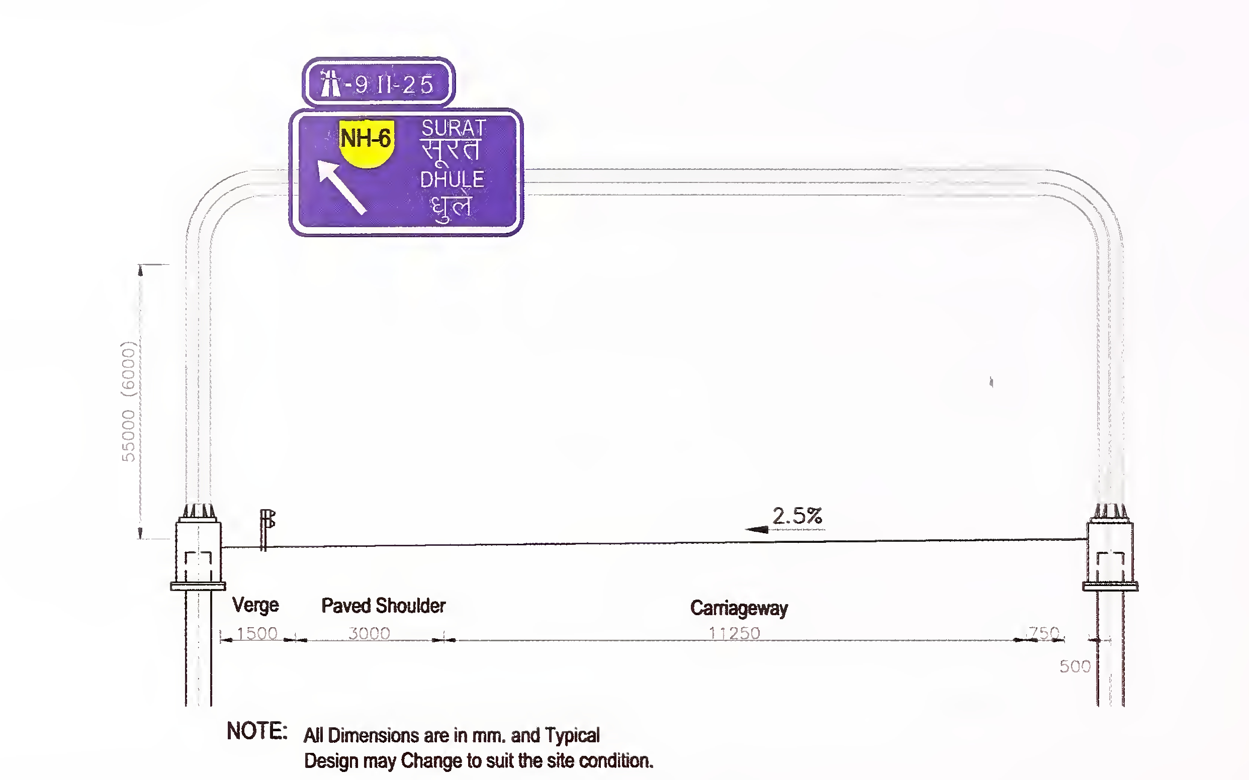
Fig. 10.1 A Typical Overhead Mounted Structure
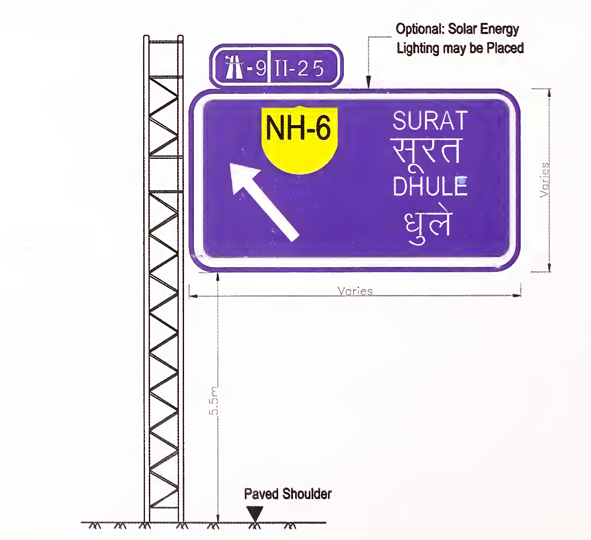
Fig. 10.1B Typical Exit Gore Sign90
Fig. 10.2 Expressway Symbol Sign
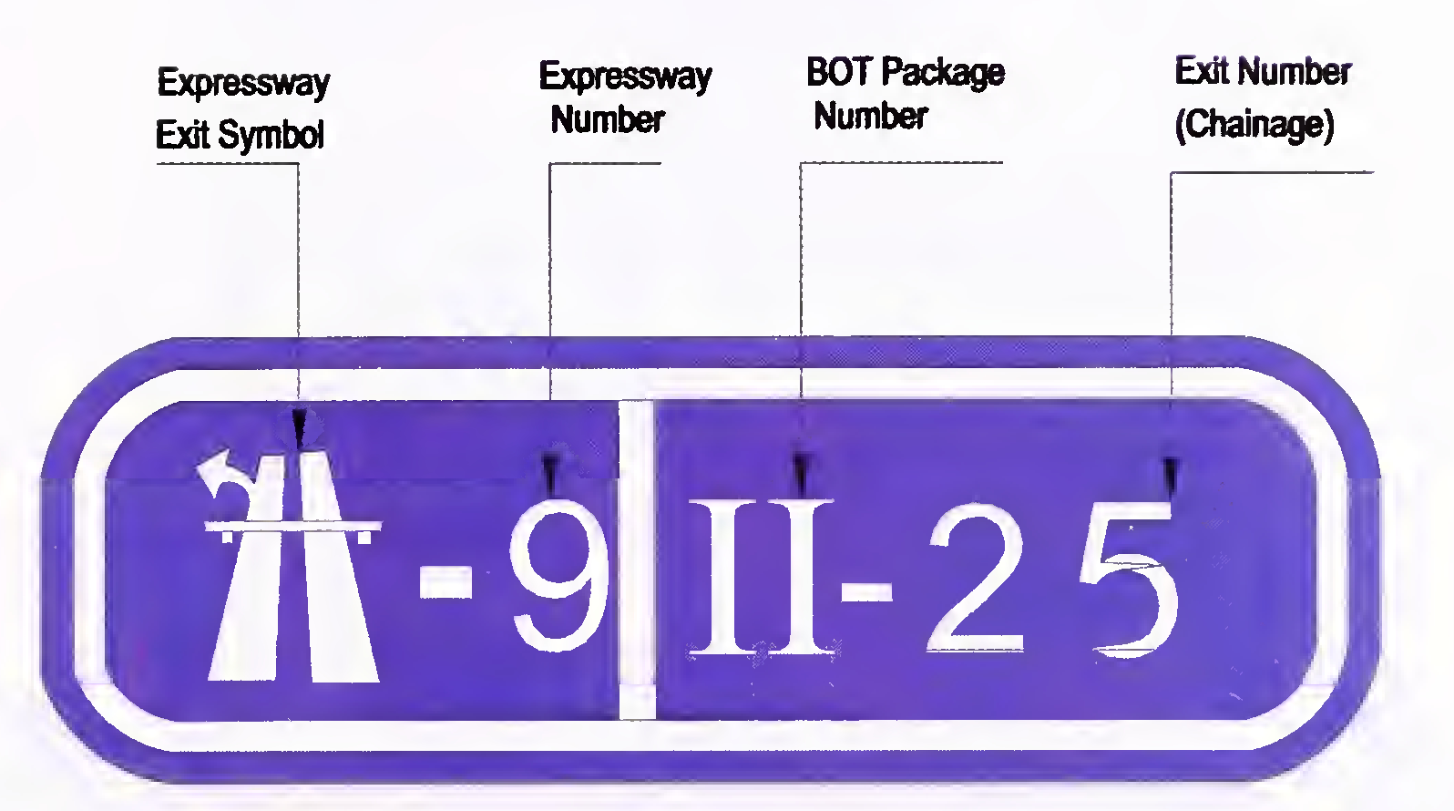
Fig. 10.3 Typical Exit km - Numbering Sign
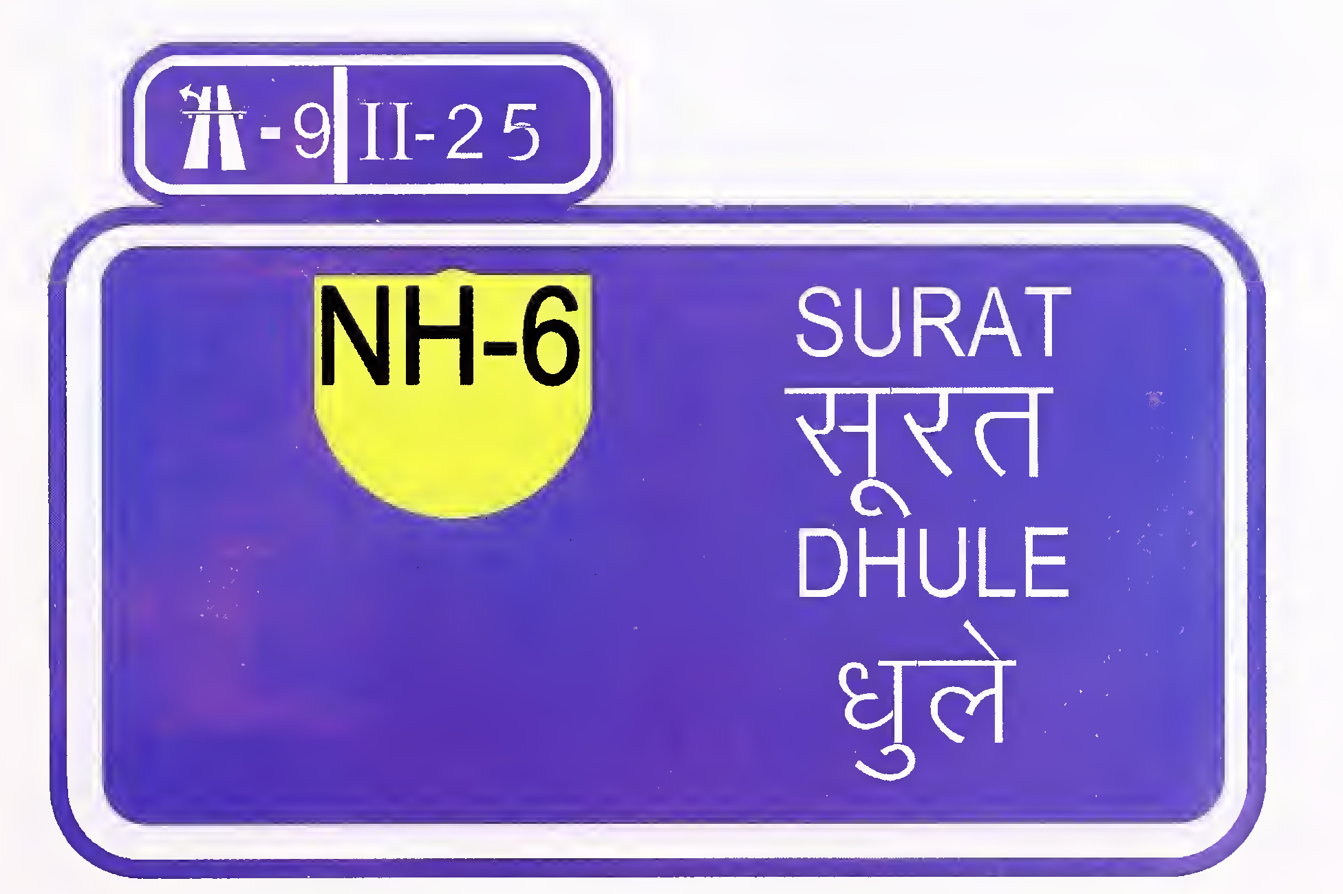
Fig. 10.4 Typical Interchange Advance Guide Sign91
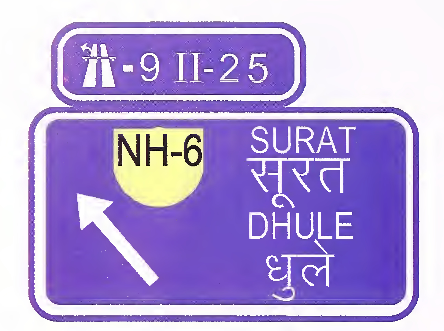
Fig. 10.5 Typical Exit Direction Sign

Fig. 10.6 Typical Exit Gore Sign
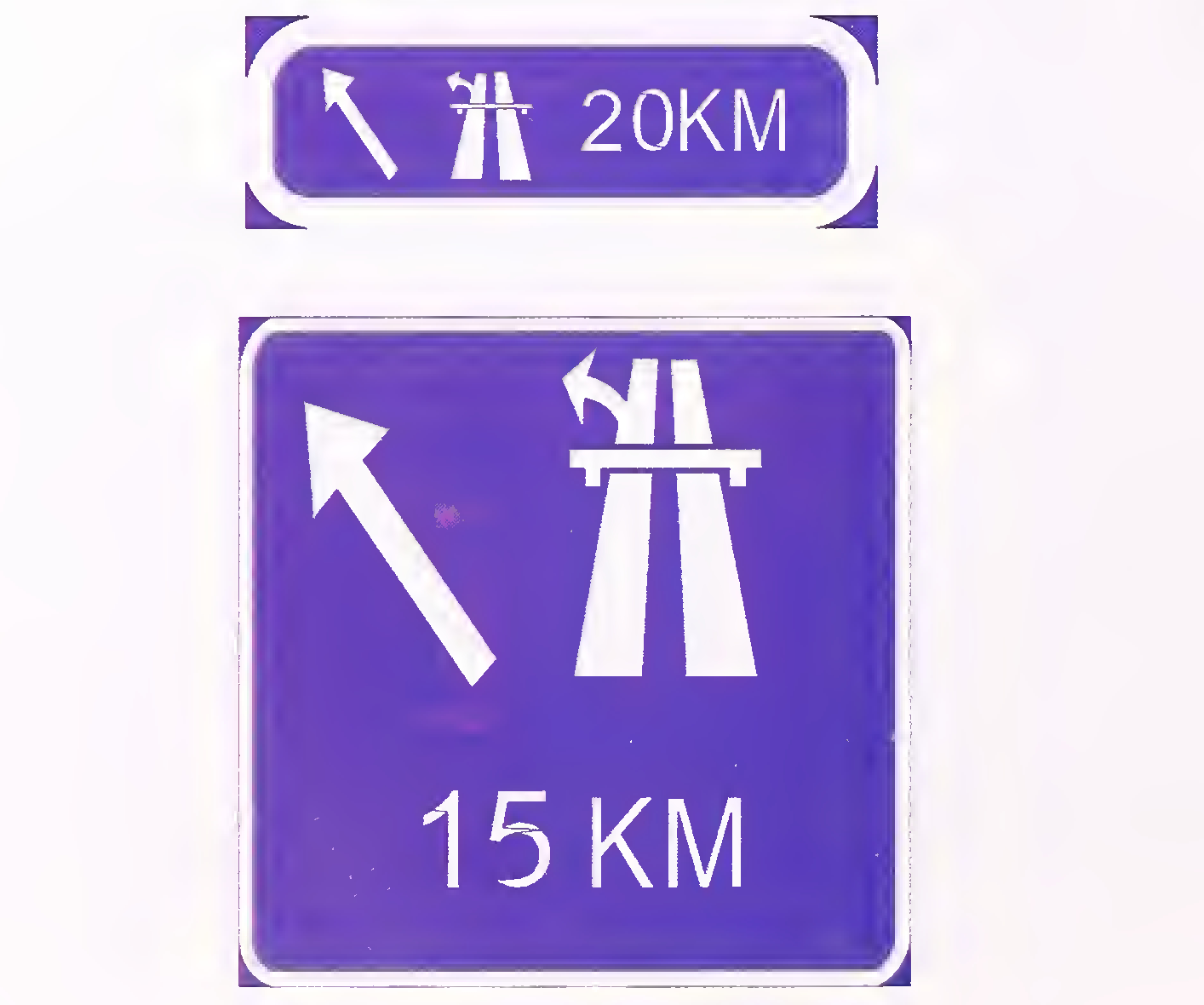
Fig. 10.7 Next Supplemental Sign92
Fig. 10.8 End of Expressway Sign
Fig. 10.9 Typical Distance Sign (Reassurance Sign)93
Fig 10.10 Signing Plan for Trumpet Intercliange94
Fig 10.11 Typical layout of Diamond Interchange Sign95
Fig. 10.12 Typical Layout for Full Cloverleaf Interchange Sign96
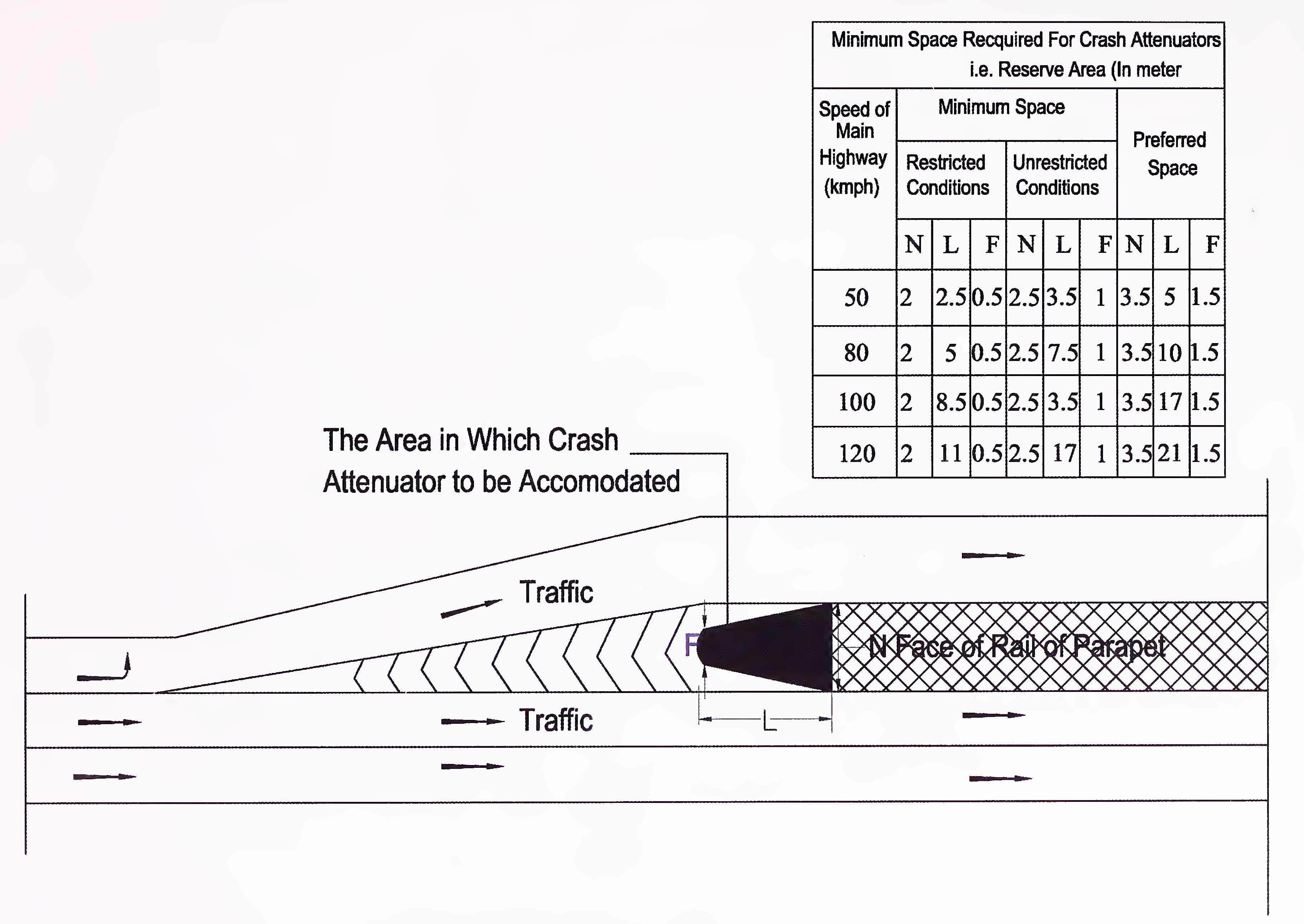
Fig. 10.13 Space Required to Place Crash Attenuators97
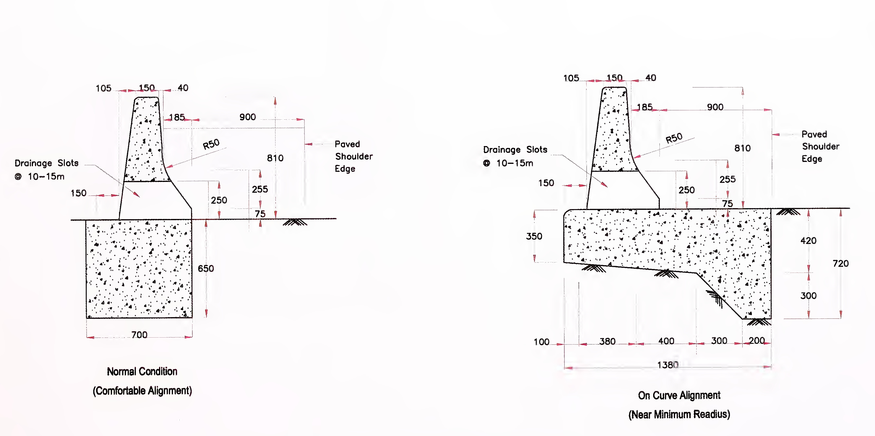
Fig. 10.14 Typical Road Side Concrete Barrier98
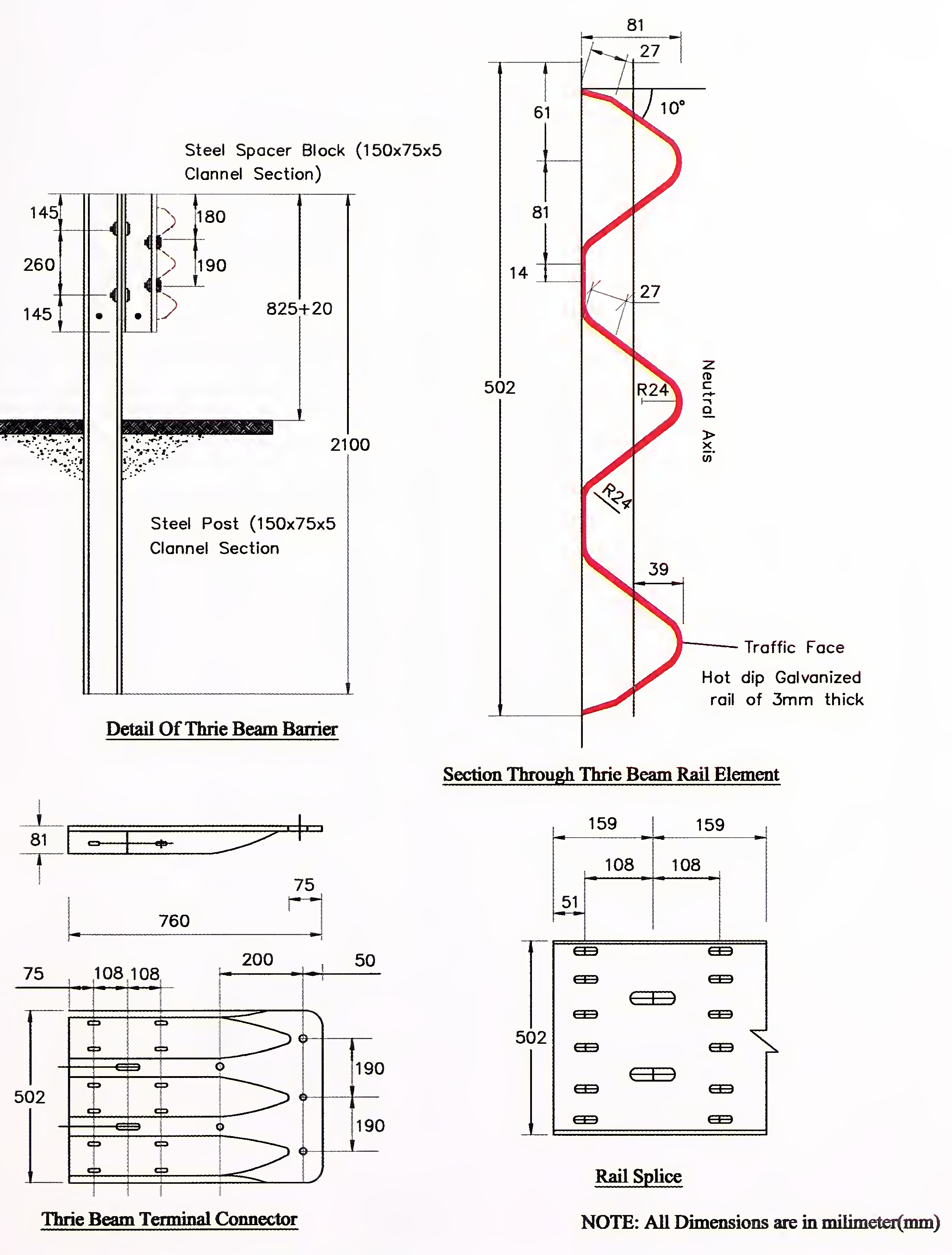
Fig. 10.15 Typical Details of Thrie Beam Structural Elements99
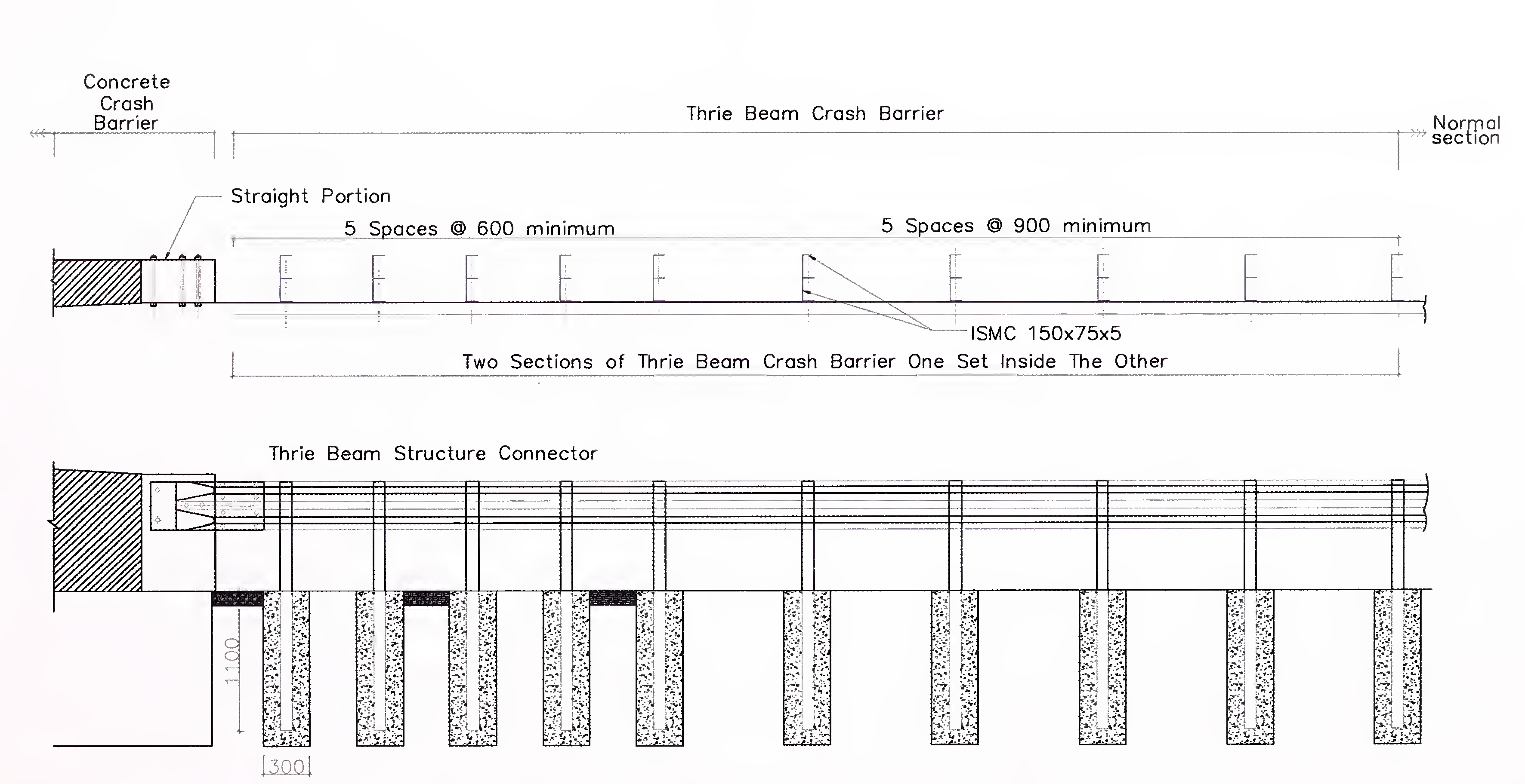
Fig. 10.16 Thrie Beam to Concrete Barrier Connection Details100
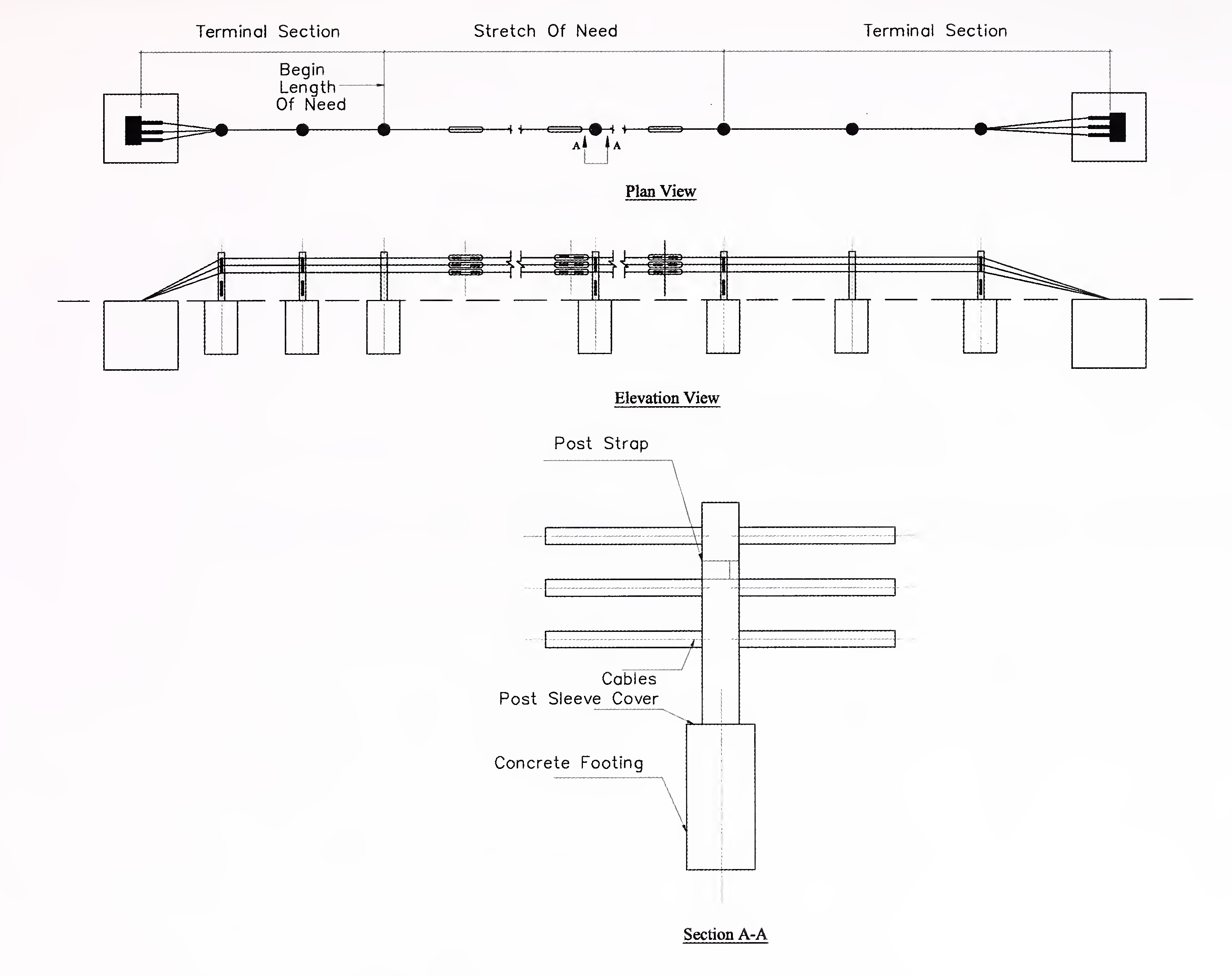
Fig. 10.17 Typical Details of Wire Rope Safety Barrier101
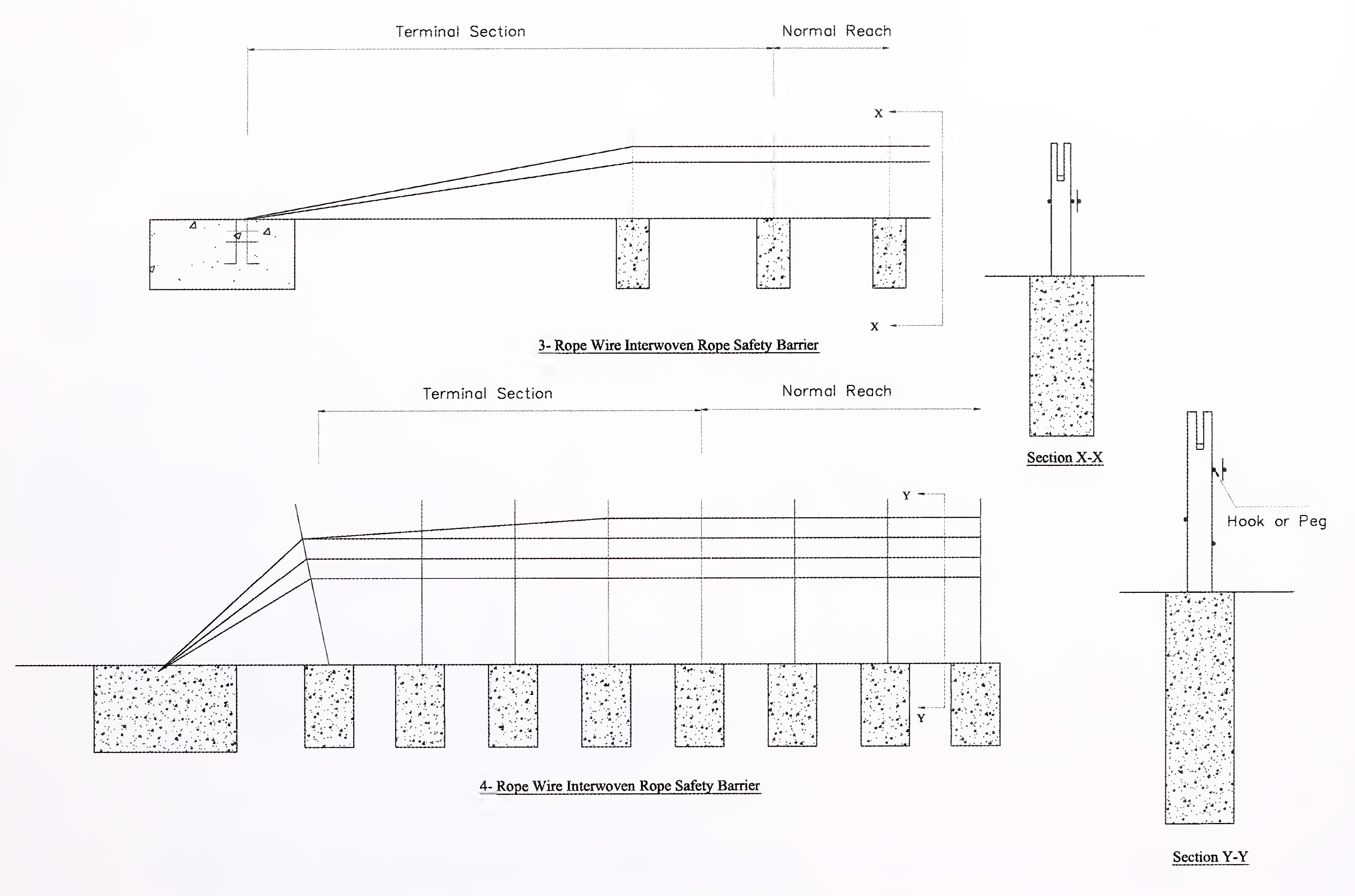
Fig. 10.18 Typical Details of Wire Rope (Interwoven) Safety Barrier102
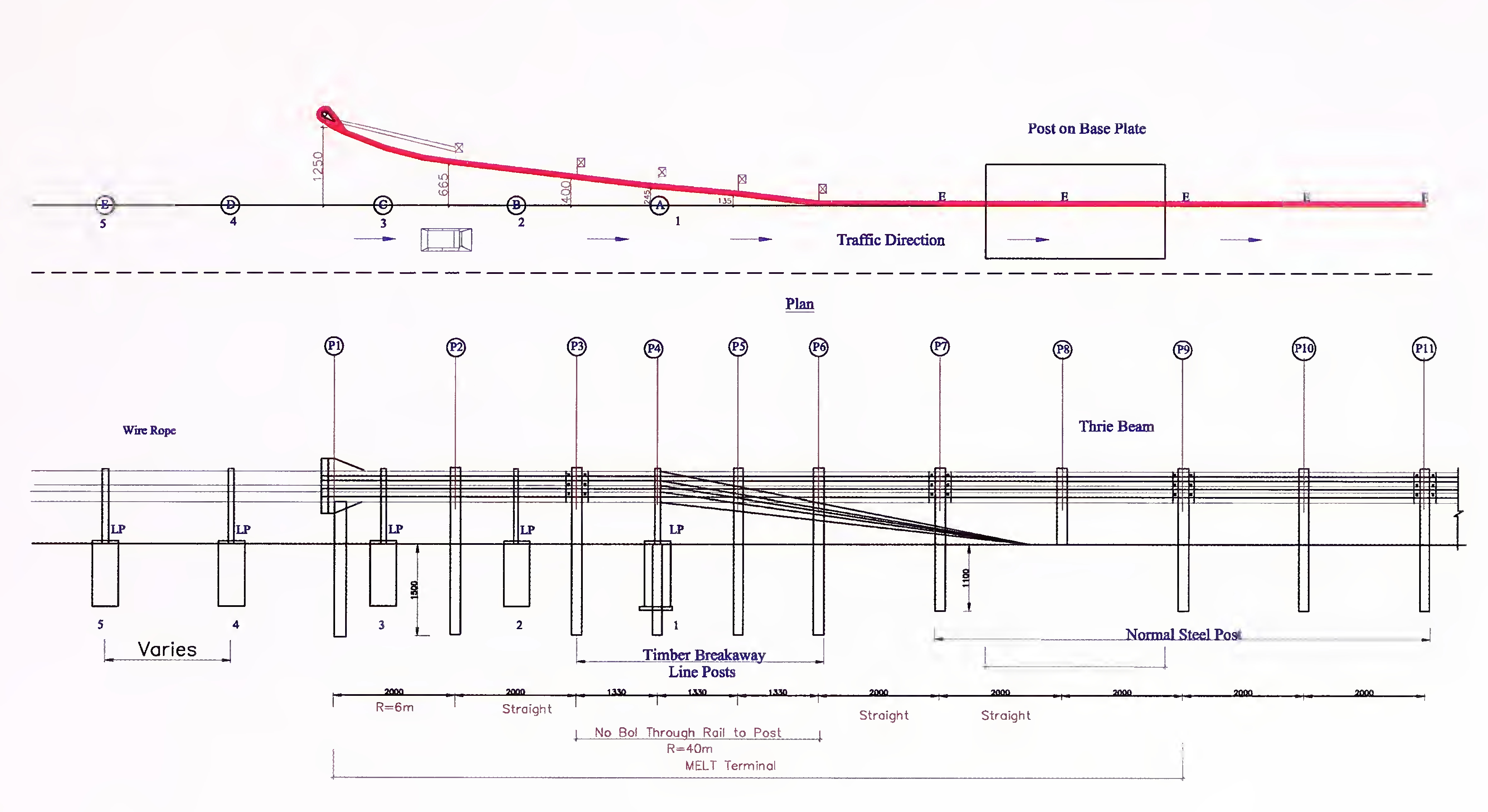
Fig. 10.19 Typical Details of Wire Rope to Beam Barrier103
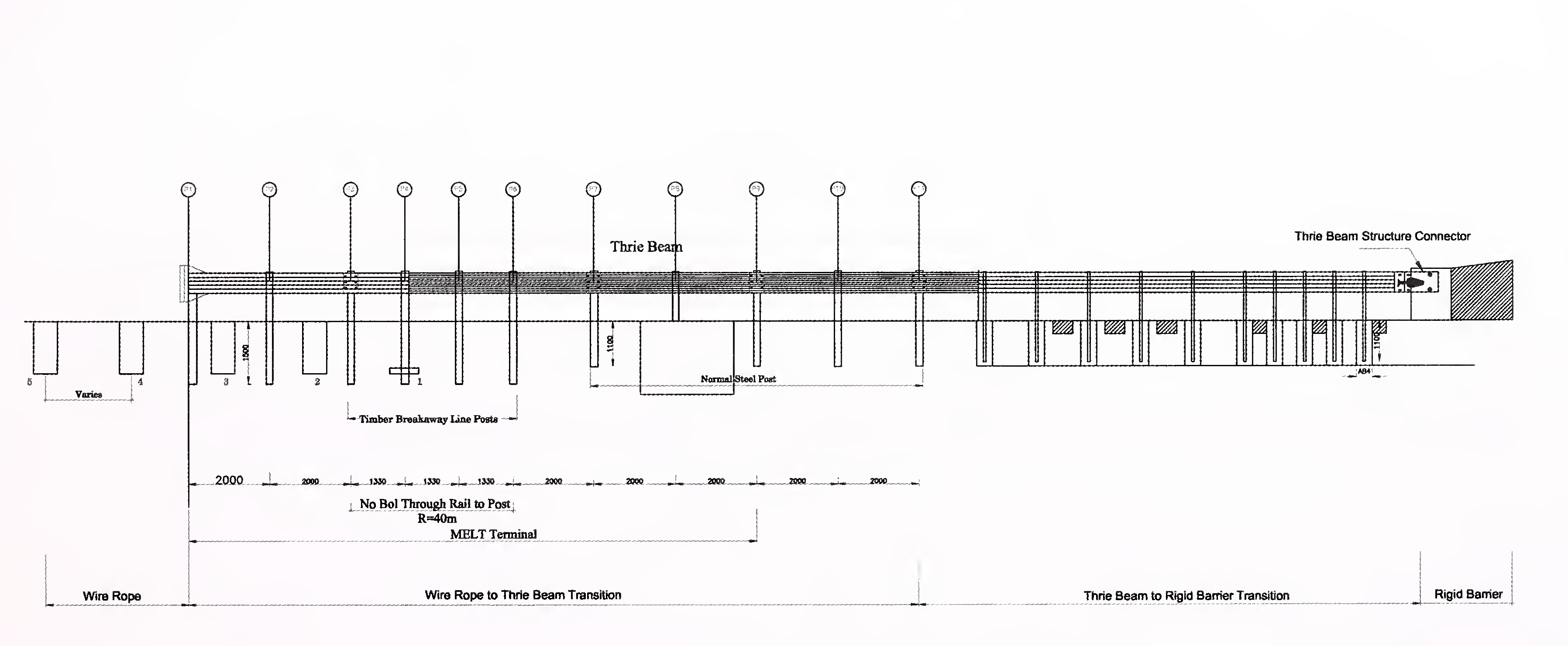
Fig. 10.20 Typical Details of Wire Rope to Rigid Barrier104
Advance Traffic Management Systems (ATMS) shall be provided as per Clause 816 of MORTH Specifications for road and bridge works.
ATMS shall have the following sub-systems.
Locations of each component of Advanced Traffic Management System shall be as specified in Schedule-B of the Concession Agreement.105
The Concessionaire shall provide the Toll Plaza(s) for collection of toll/fee as per the Concession Agreement. The fee collection system shall be electronic toll collection (ETC) system, unless specified otherwise in Schedule-C of the Concession Agreement. The design of the Toll Plaza(s) should be aesthetically pleasing. The fee collection staff where it becomes necessary to collect toll fee through cash or smart card should be efficient, courteous and adequately trained before deployment.
The Toll Plaza shall be located at every entry/exit ramp onto/from the Project Expressway. A typical location of a toll plaza, a toll office, and a maintenance office is given in Fig. 12.1.
Adequate land for Toll Plaza shall be acquired to permit the provision of toll lanes for a projected peak hour traffic of 25 years or the concession period whichever is more including all other buildings and structures to be accommodated at the Toll Plaza location. Land shall be acquired as per provisions of the Concession Agreement.
Where Schedule-C of the Concession Agreement specifies collection of toll/fee through a combination of cash, smart card and ETC system, the Toll Plaza shall comprise of following elements:-106
Fig. 12.2 presents Schematic Arrangement of Services facilities at toll plaza.
Fig. 12.3 and Fig. 12.4 present Typical Layout of Toll Plaza.
The layout shall provide for future expansion of toll lanes. Stage construction of Toll Plaza in respect of number of toll lanes shall be allowed. However, other structures as envisaged in the Concession Agreement shall be provided at the initial stage itself.
The width of each ETC toll lane shall be 3.5 m, except for manual/smart card lanes, where it shall be 3.2 m, and the lane width for over dimensioned vehicles, where it shall be 4.5 m.
Between each toll lanes of the toll plaza meant for collection through manual/smart card, toll islands are required to accommodate toll booth. These islands shall be of minimum 25 m length and 1.8 m width. Protective barriers of reinforced concrete and traffic impact attenuators shall be placed at the front of each island to prevent out of control approaching vehicles crashing into the toll booth. They shall be painted with reflective chevron markings.
Toll booths may be provided of prefabricated materials or of masonry. The toll booths shall have adequate space for seating of toll collector, computer, printer, cash box, etc. It should107
have provision for light, fan and air conditioning. The typical details of traffic island with toll booth are given in Fig. 12.5.
Toll booth shall be placed at the centre of each traffic island. The toll booth shall have large glass window to provide the toll collector with good visibility of approaching vehicles. The bottom of the window should be placed at such a height (0.9 m) above ground level as to provide convenience of operation. The toll booths shall be ergonomically designed and vandal proof. There shall be CCTV camera installed at each booth.
For the movement between toll office and toll booths of lane, an underground tunnel/overbridge across all toll lanes shall be provided. Its dimension should be sufficient to accommodate the required wiring/cable system and for convenient movement of personnel. It should also be provided with lighting and ventilation system so that the movement is convenient.
The total number of toll booths and lanes shall be such as to ensure the service time of not more than 10 seconds per vehicle at peak flow regardless of methodology adopted for fee collection. For purpose of guidance following parameters are suggested as capacity of individual toll lane for design purpose:
Not less than 2 middle toll lanes shall be capable of being used as reversible lanes to meet the demand of tidal flow. One additional lane on either side shall be provided for over dimensioned vehicles.
Toll plazas shall be designed for projected peak hour traffic of 25 years or the Concession Period whichever is more. Stage construction of toll plaza in respect of number of toll lanes shall be allowed provided the design caters for a minimum period of 15 years. If at any time, the queue of vehicles becomes so large that the waiting time of the user exceeds three minutes, the number of toll lanes shall be increased and/or system of collection improved so that the maximum waiting time is brought down to less than three minutes.
At entry and exit of the toll booths, the rate of taper for transition length for the carriageway of expressway and ramp carriageway shall be 1:25 and 1:15 respectively.
Removable type barriers shall be provided for emergency or maintenance area cross over and to accommodate reversible toll lanes.108
All the toll lanes and toll booths shall be covered with a canopy. The canopy shall be wide enough to provide weather protection to toll operators, drivers and facilities. The canopy shall be of aesthetically pleasing design with cylindrical support columns located at traffic island so that there is no restriction on visibility and traffic movement. The vertical clearance shall be as prescribed in this Manual.
The toll plaza shall be provided with surface and sub-surface drainage system so that all the storm water is drained off efficiently and no ponding or stagnation of water takes place at any area of the toll plaza.
Toll collection system shall comprise of the following equipment/systems;
All equipment shall have built-in or external surge protection system.
Toll plaza location shall also be provided with system for checking and preventing overloading of vehicles at toll plaza. WIM should be installed at least 500 m ahead of Toll Plaza. Vehicles found to be overloaded shall not be allowed to use the Expressway.
Concrete pavement shall be provided in the Toll Plaza area including tapering zone, from durability and longtime serviceability consideration. The rigid pavement shall be designed as per IRC:58.109
A well thought out strategy should be evolved for providing traffic signs and road markings in and around the Toll Plaza in accordance with IRC:67 and IRC:35. The Concessionaire would design the configuration/placement of such signs for toll plaza as are not given in IRC:67 and furnish to the Independent Engineer for review so as to ensure uniformity of signs in use on all the highways across the country.
Signs should be placed along the Project Expressway, roadway of Toll Plaza to guide and render assistance to the drivers approaching the Toll Plaza. It is necessary to alert the driver about the existence of Toll Plaza two km ahead with repeaters sign 1 km and 500 m ahead. Stop sign shall always be used in combination with certain road markings such as stop line and the word ‘STOP’ marked on the pavement.
The Toll Plaza sign should be supplemented by the sign advising the users of the notified toll rates (fees) for various types of vehicles and exempted categories of vehicles.
Appropriate Signs and Signals shall also be provided on the canopy of toll plaza to properly guide the approaching vehicles about the lane in operation, lane applicable to specific category of vehicle, lane with Electronic Toll System, reversible lane, etc. Fig. 12.6 presents details of Traffic Signs and Road Markings in Toll Plaza
The road markings shall be used in accordance with Section-10 of this Manual. The road markings for the Toll Plaza area shall consist of lane markings, diagonals, chevron markings. Single centre line is provided at the centre of carriageway at toll gate to demarcate each service lane. Diagonal markings for central traffic island and chevron markings at side traffic island shall be provided to guide the approaching and separating traffic.
In order to control overspeeding of the vehicle approaching toll booth, transverse bar markings, as per typical details given in Fig 12.7 shall be provided.
The toll plaza shall have lighting system to provide visibility to drivers for the use of facility especially to access the correct service lane and also to the toll collector. Indian Standard ‘Code of Practice for Lighting of Public Thoroughfare’ IS: 1944 shall be followed. This would be done by interior and exterior lighting as indicated below. Power supply shall be from public power supply system, but standby generating set of the capacity to supply the required power shall be provided at toll plaza.
The lighting system shall consist of the following major components.
Sodium Vapour lamp of 200-250 watts should be provided for these poles on both sides at 50 m staggered spacing. There should be provision for flashing signals for foggy weather conditions.
Adequate water supply shall be provided. For working out water requirement and internal drainage system, reference may be made to IS: 1172, IS:5339 and IS: 1742.
Toll Plaza shall have fire/fighting equipment, including smoke detectors and audio visual alarm system as per Section 4.17.1 of National Building Code, so that the personnel working in the complex and the office and the road users are protected against fire hazards.
Toll plaza shall have a separate office building so as to provide comfortable office space for manager, cashier and other staff. There shall be separate rooms for TV monitors, meetings, toilets, and for the sale of passes, smart cards, on board units and public interaction. The building shall have a strong room for keeping the cash and a garage to accommodate the security van (during operation of loading the collected revenue). There shall be parking space111
in the same campus for vehicles for the staff and workers and other vehicles engaged in the operation of the Project Expressway.
The size of the office complex depends on the minimum requirement of above facilities Provision for future expansion: The office building shall be located taking into consideration of future expansion.
U-turn ramp shall be installed near the toll plaza for vehicles operated by Operations Management personnel for safe operations as indicated Fig. 12.2.
“Closed system of toll collection” shall be adopted. Closed System of tolling means that payment need to be made only at the exit by either charging the same to the On-Board Unit on the wind-screen of the vehicle passing through the ETC lane or depositing the ticket collected at the entry.
A closed toll system has an entrance and exit booth for the toll system and captures all users and revenue of the system. Toll plazas are located at every interchange preventing diversion around main lane toll plazas. Upon entering the toll system, the On-Board Unit on the vehicle of the user is read. In case of manual/smart card collection system, the user receives a ticket. When exiting, the user gives the ticket to the toll collector and is charged a set fee as per policy decision and notification. In case of ETC system, the tag on that vehicle of the user is charged accordingly.
The design and layout of Toll Plaza complex including all facilities shall be submitted to the Independent Engineer for review and comments, if any.112
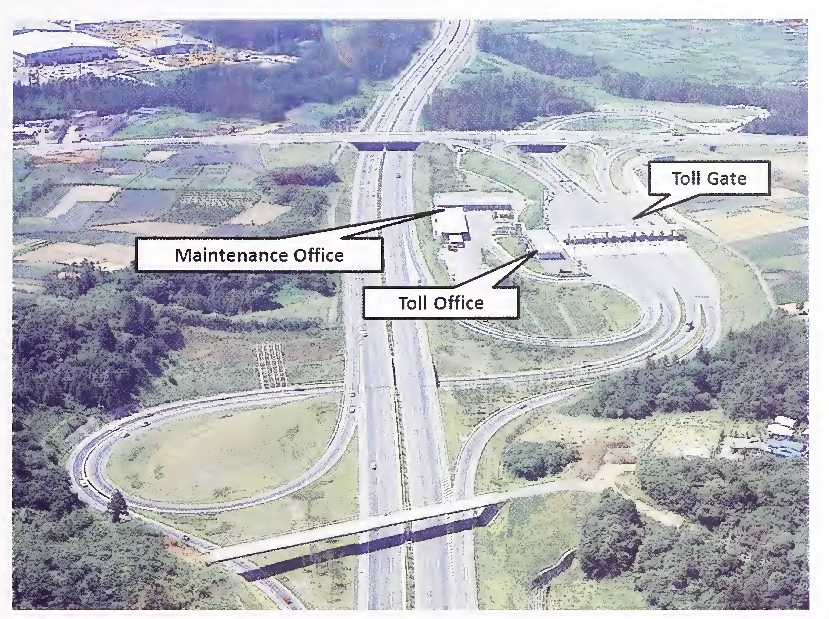
Fig. 12.1 Typical Location of Toll plaza, Toll Office, and Maintenance Office at Trumpet-type Interchange113
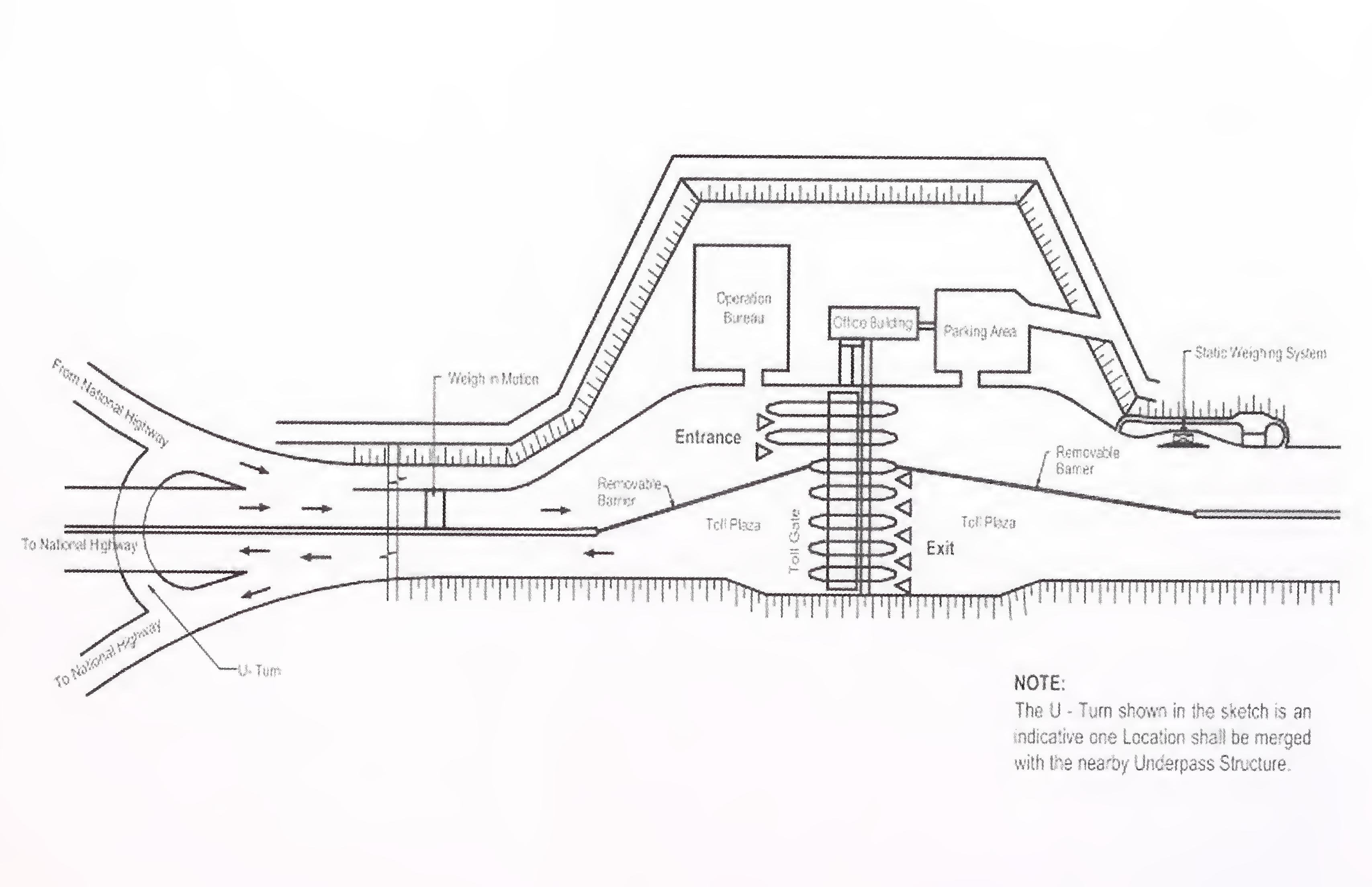
Fig. 12.2 Schematic Arrangement: Service Facilities at Toll Plaza114
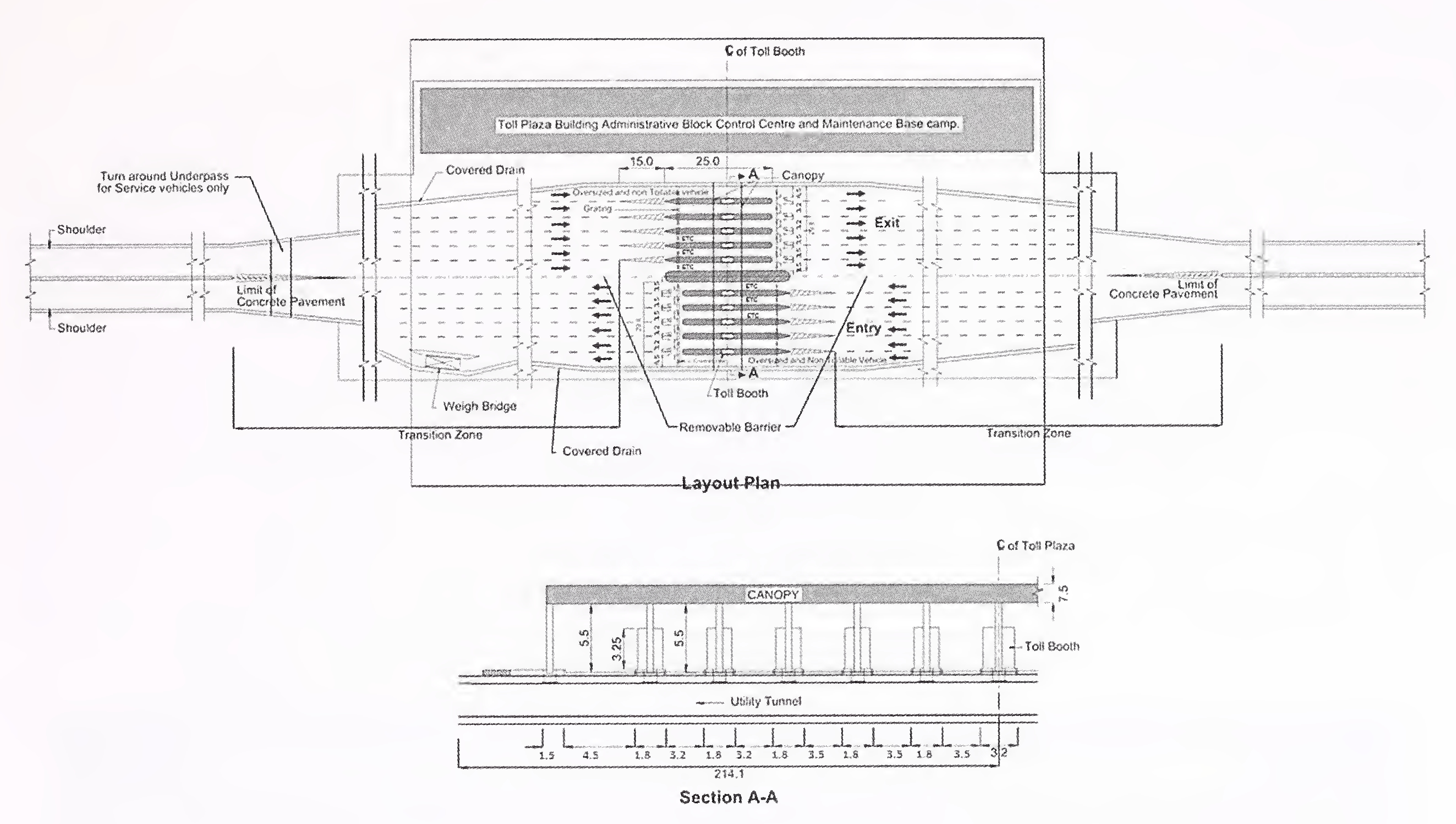
Fig. 12.3 Typical Layout of Toll Plaza115
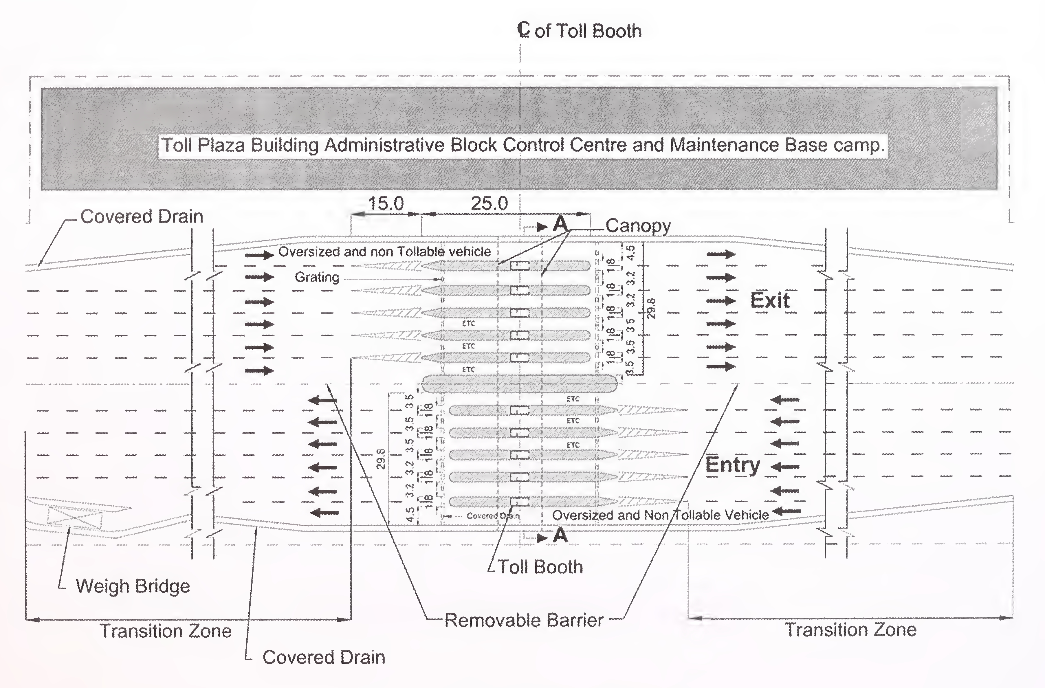
Fig. 12.4 Toll Plaza Area (ETC Lanes at Center)116
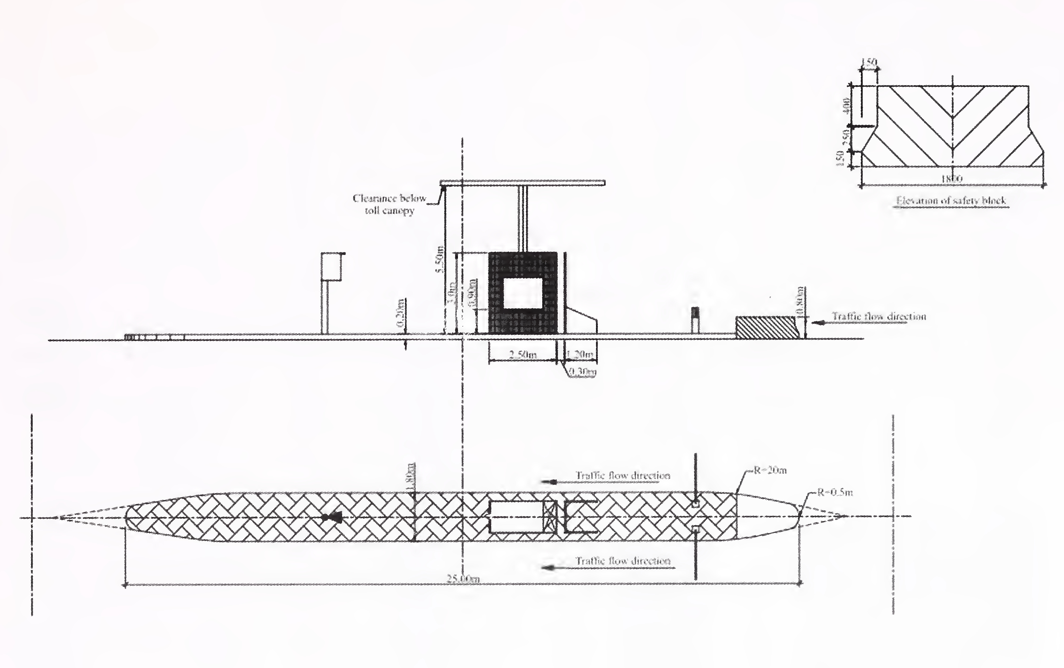
Fig. 12.5 Typical Layout for Traffic Island with Toll Booth117
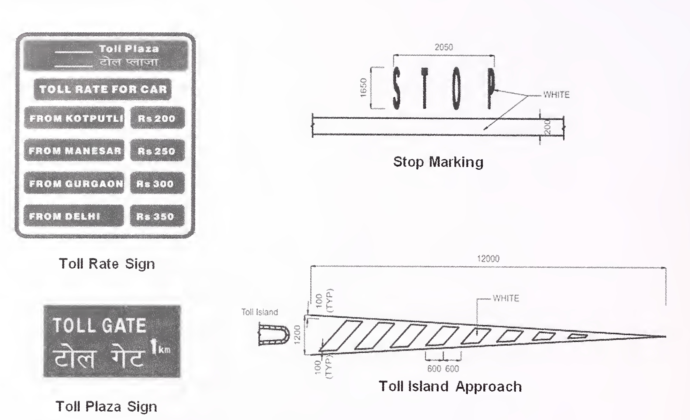
Fig. 12.6 Traffic Signs and Road Markings in Toll Plaza
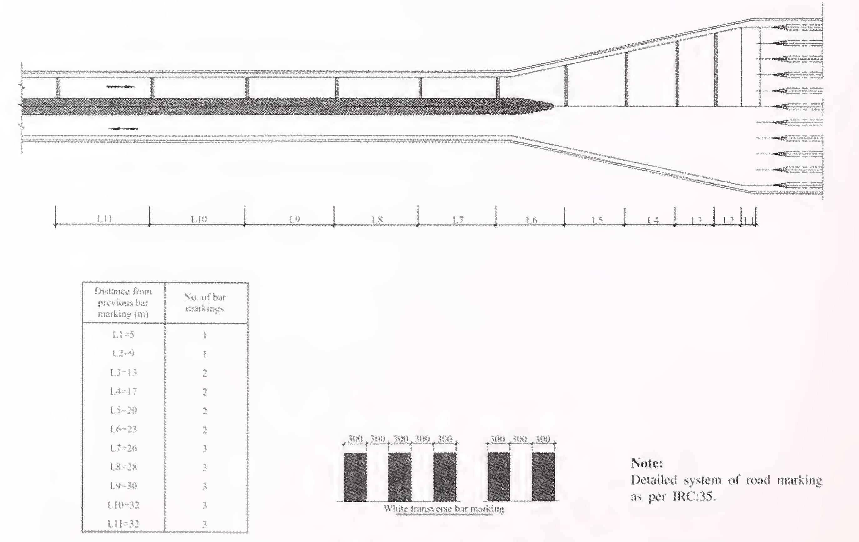
Fig. 12.7 Details of Suggestive Transverse Bar IVIarking for Speed Control at Toll Plaza118
Service areas shall be planned and provided as wayside amenities for users of the expressways to enable them to stop, take rest and refresh themselves so as to ease their fatigue. These areas also cover facilities for providing fuel for vehicles and emergency requirements without having to exit from the expressway. Thus, provision of service areas and their operation and maintenance are to be an integral part of the Project Expressway for comfortable and safe driving.
The principal users of the expressway are passenger car users, bus users, goods vehicles drivers and other attendants. The service area shall provide the following facilities for the expressway users.
above. A minimum area of five hectares shall be provided. The service area upto fifteen hectares is considered generally manageable and this will provide enough space for landscaping and allow for future expansion requirements with growth of traffic on the expressway.
| Percent Heavy Vehicles | ADT-20000 vpd | ADT-40000 vpd | ||||||
|---|---|---|---|---|---|---|---|---|
| Urinals | Men’s | Women’s | PwD | Urinals | Men’s | Women’s | PwD | |
| 30 | 8 | 4 | 8 | 2 | 14 | 6 | 12 | 2 |
| 40 | 8 | 4 | 8 | 2 | 14 | 6 | 12 | 2 |
| 50 | 6 | 4 | 6 | 2 | 10 | 4 | 8 | 2 |
| 60 | 6 | 4 | 6 | 2 | 10 | 4 | 8 | 2 |
| PwD = Persons with Disabilities | ||||||||
| Percent Heavy Vehicles | ADT-20000 vpd | ADT-40000 vpd | ||||||
|---|---|---|---|---|---|---|---|---|
| Urinals | Men’s | Women’s | PwD | Urinals | Men’s | Women’s | PwD | |
| 30 | 6 | 4 | 2 | 2 | 10 | 6 | 4 | 2 |
| 40 | 6 | 4 | 2 | 2 | 10 | 6 | 4 | 2 |
| 50 | 8 | 4 | 4 | 2 | 12 | 8 | 6 | 2 |
| 60 | 8 | 4 | 4 | 2 | 12 | 8 | 6 | 2 |
| PwD = Persons with Disabilities121 | ||||||||
For design considerations of various facilities, reference may also be made to MORTH Guidelines for Expressways.
The operators of bus services plying on the expressway would require facility of bus stops at important towns and village settlements en-route served by the expressway for enabling the passengers to either get down or to pick-up the passengers wanting to get in. Since the expressway is not open to pedestrians, the bus stops have to be located outside the Right of Way of the expressway to ensure safe and unimpeded travel.
The pick-up bus stops shall be located at the inter-change points and planned in a manner that passengers are kept away from the expressway facility. The pick-up bus stops shall not be located in the Service Area except where the service area itself is planned at an interchange point. The location of pick-up bus stops shall be as given in Schedule-C of the Concession Agreement.
Basically, the design and layout of the pick-up bus stops may be integrated with local bus services and intermediate public transport (auto rickshaws, taxis, etc.). Adequate transit facility shall be planned and provided accordingly. Being a closed system of tolls to be adopted on expressways, there shall be specially designed access road for buses exiting from the expressway to the bus-stop and thereafter entering the expressway such that the bus does122
not leave the access road except for letting the passengers get down from the bus or get into the bus from the pick-up bus stops. Fig. 13.2 presents a typical functional arrangement of pick-up bus stops at the Expressway combined with local bus stop facility.
The state border check posts shall be planned and provided to enable the State Authorities to exercise checks as per Applicable Laws on the vehicles crossing the state border. Such checks may be related to sales tax, VAT, entry tax, tourist permit tax, forest related taxes, etc.
The check posts shall be provided on laybyes off the Expressway shoulders with proper deceleration and acceleration lanes. Further, such laybyes will be located immediately after crossing the state border. The location of check posts shall be as given in Schedule-C of the Concession Agreement.
The design of the check post will be undertaken in consultation with the State Authorities. Normally, a built-up area of 300 sqm would suffice including the toilet facilities. An open area of around 300 sqm adjoining the building block shall be reserved for parking of vehicles. Typical layout is given in Fig. 13.3.123
Annex 13.1
Broad Guidance for Assessment of Parking Spaces in Service Areas
Then the number of parking spaces will be given by the equation.
N = ADT × UR × DHF × L
Where N = number of parking spaces
ADT = Average Daily Traffic in the direction of service area
UR = Usage Ratio
DHF = Design Hour Factor
L = Stay in Hours
| Type of Vehicle | UR | DHF | L | Number (N) of Parking Spaces (per 1000 vpd of a Particular Class in one Direction) |
|---|---|---|---|---|
| Cars | 0.15 | 0.10 | 30/60 | 7.5 per 1000 cars |
| Buses | 0.20 | 0.12 | 24/60 | 9.6 per 1000 buses |
| Trucks | 0.15 | 0.12 | 36/60 | 10.8 per 1000 trucks |
| Class | Percent Composition Assumed | |||
|---|---|---|---|---|
| Case I | Case II | Case III | Case IV | |
| Cars | 75 | 70 | 63 | 50 |
| Buses | 5 | 5 | 7 | 10 |
| Trucks | 20 | 25 | 30 | 40 |
| Percent of CVs | Number of Parking Spaces | |||||
|---|---|---|---|---|---|---|
| Case | Trucks | Buses | Cars | Buses | Trucks | PwD |
| Case I | 20 | 5 | 114 | 10 | 44 | 4 |
| Case II | 25 | i 5 | 106 | 10 | 54 | 4 |
| Case III | 30 | 7 | 96 | 14 | 66 | 4 |
| Case IV | 40 | 10 | 76 | 20 | 88 | 4 |
| PwD = Persons with Disabilities | ||||||
| Percent of CVs | Number of Parking Spaces | ||||
|---|---|---|---|---|---|
| Trucks | Buses | Cars | Buses | Trucks | PwD |
| 20 | 5 | 60 | 5 | 25 | 2 |
| 25 | 5 | 50 | 5 | 30 | 2 |
| 30 | 7 | 50 | 7 | 35 | 2 |
| 40 | 10 | 40 | 10 | 45 | 2 |
| PwD = Persons with Disabilities125 | |||||
Annex 13.2
PROVISIONS FOR PERSONS WITH DISABILITIES (PwD)
For this Manual, the disabilities mean which confine individuals to wheel chair for mobility. The standard size of wheel chair as generally considered is 1,050 mm × 750 mm.
At the wayside amenity centres/rest areas, the level of the roads, access paths and parking areas require special considerations as described below:
Access PathA/Walk Way: Access path from entry to parking lot and to facility centre shall be minimum of 1,800 mm wide having even surface without any steps. Slope, if any, shall not have gradient greater than 5 percent. Finishes shall have a non slip surface with a texture traversable by a wheel chair as well as for trolley baggage. Kerbs wherever provided should blend to a common level.
Parking: For parking of vehicles, the following provisions are required:
- Surface parking for at least two Car Spaces shall be provided near entrance, with maximum travel distance of 30 m from facility entrance.
- The width of parking bay shall be minimum 3.6 m.
- The signage for reserved space for wheel chair users shall be conspicuously displayed using large sign boards.
- The slope of parking spaces reserved for Persons with Disabilities (PwD) on wheel chair especially should not exceed 1 (one) percent gradient. Fig. 13.1G presents typical layout.
- Ramp should be complemented by flights of steps, as many people (crutch users) have more difficulty coping with ramps than steps, particularly when descending.
- Landings - every 750 mm of vertical rise, width should be 1800 mm wide to permit wheelchairs to pass. Over short lengths, a minimum width of 1200 mm can be accepted. Fig. 13.1H presents typical arrangement.
Ramped Facilities: Ramp shall be finished with non slip material to enter the facility. Minimum width of ramp shall be 1,800 mm with maximum gradient 1 V:20H.
Exit/Entrance Door: Minimum clear opening of the entrance door shall be 900 mm and it shall not be provided with a step that obstructs the passage of a wheel chair.
Entrance landing: Entrance landing shall be provided adjacent to ramp with the minimum dimension 1,800 mm x 2,000 mm. the entrance landing that adjoin the top end of a slope shall be provided with floor materials to attract the attention of persons (limited to coloured floor material whose colour and brightness is conspicuously different from that of the surrounding floor materials). Finishes shall have a non slip surface with a texture traversable by a wheel chair.126
Flooring:
Lifts: Wherever lift is required, provision shall be kept for at least one space for the wheel chair, with the following cage dimensions (Bureau of Indian Standards). Clear internal depth of 1,100 mm, Internal width of 2,000 mm and Entrance door width of 900 mm.
- A hand rail not less than 600 mm long at 1,000 mm above floor level shall be fixed adjacent to the control panel.
- The lift lobby shall be of an inside measurement of 1,800 mm × 1,800 mm or more.
- The time of an automatically closing door should be minimum 5 seconds and the closing speed should not exceed 0.25 m/s.
- The interior of the cage shall be provided with a device that audibly indicated the floor the cage has reached and indicates that the door of the cage for entrance/ exit is either open or closed.
Toilets: At least one special WC in a set of toilet shall be provided for the use of handicapped with essential provision of wash basin near the entrance.
- The minimum size shall be 1,500 mm x 1,750 mm.
- Minimum clear opening of the door shall be 900 mm and the door shall swing out.
- Suitable arrangement of vertical/horizontal handrails with 50 mm clearance from wall shall be made in the toilet.
- The WC seat shall be 500 mm from the door.
Drinking Water: Suitable provision for drinking water shall be made for the handicapped near the special toilet provided for them.
Signage: Appropriate identification of specific facilities within a building for the handicapped persons should be done with proper signages. Signs should be designed and located so that they are easily legible. To ensure safe walking, there should not be any protruding sign which creates obstruction in walking. Public Address System shall be provided.127
The symbols/informations should be in contrasting colour and properly illuminated. A symbol for wheel chair shall be installed at the lift, toilet, staircase, parking areas etc., that have been kept specially for the purpose. Fig. 13.1J presents typical signages.
Other Facilities:
Fig. 13.1I, K, L and M present other facility requirements at various usage places.128
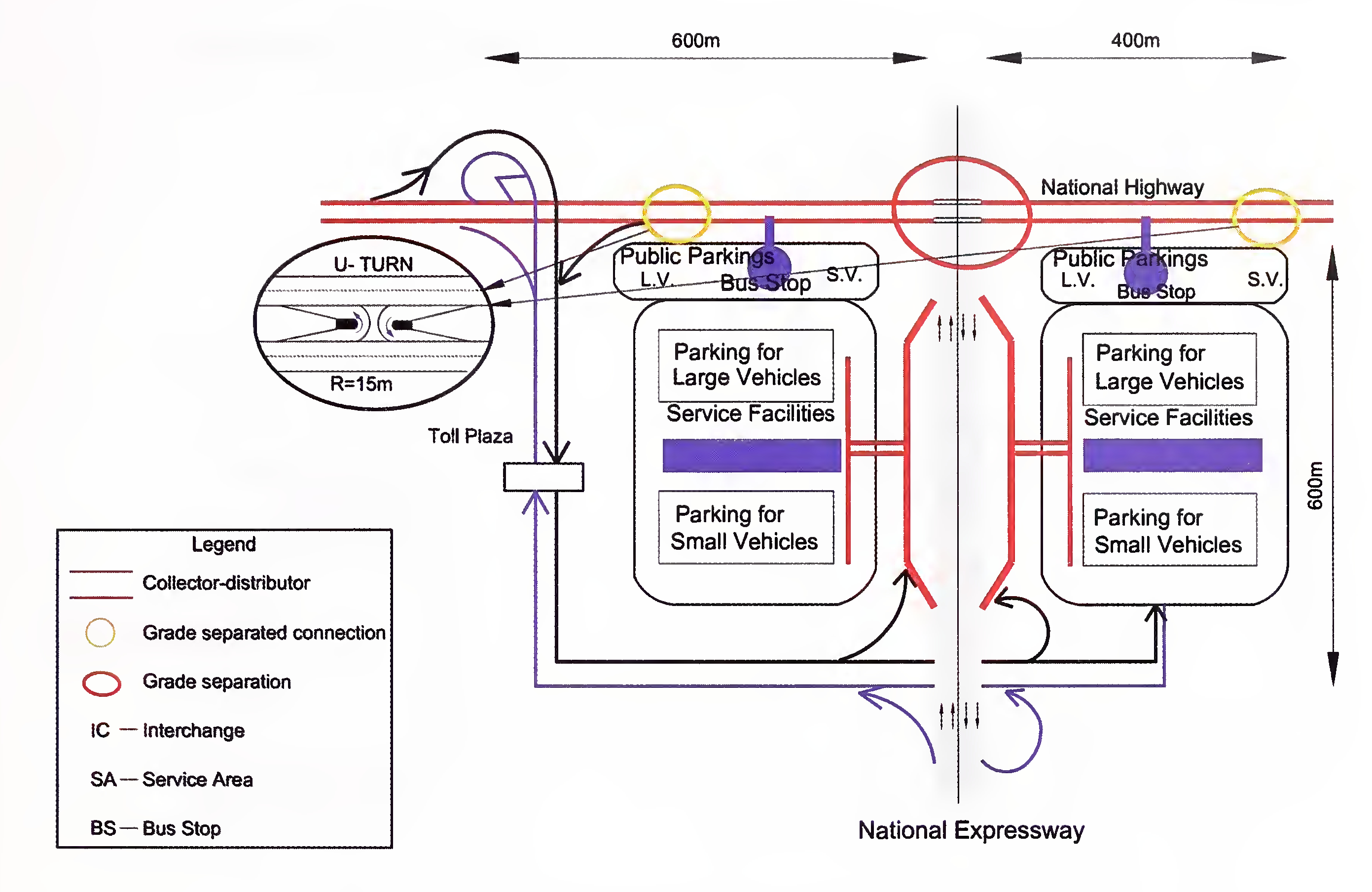
Fig. 13.1A Conceptual Drawing of IC cum SA cum BS
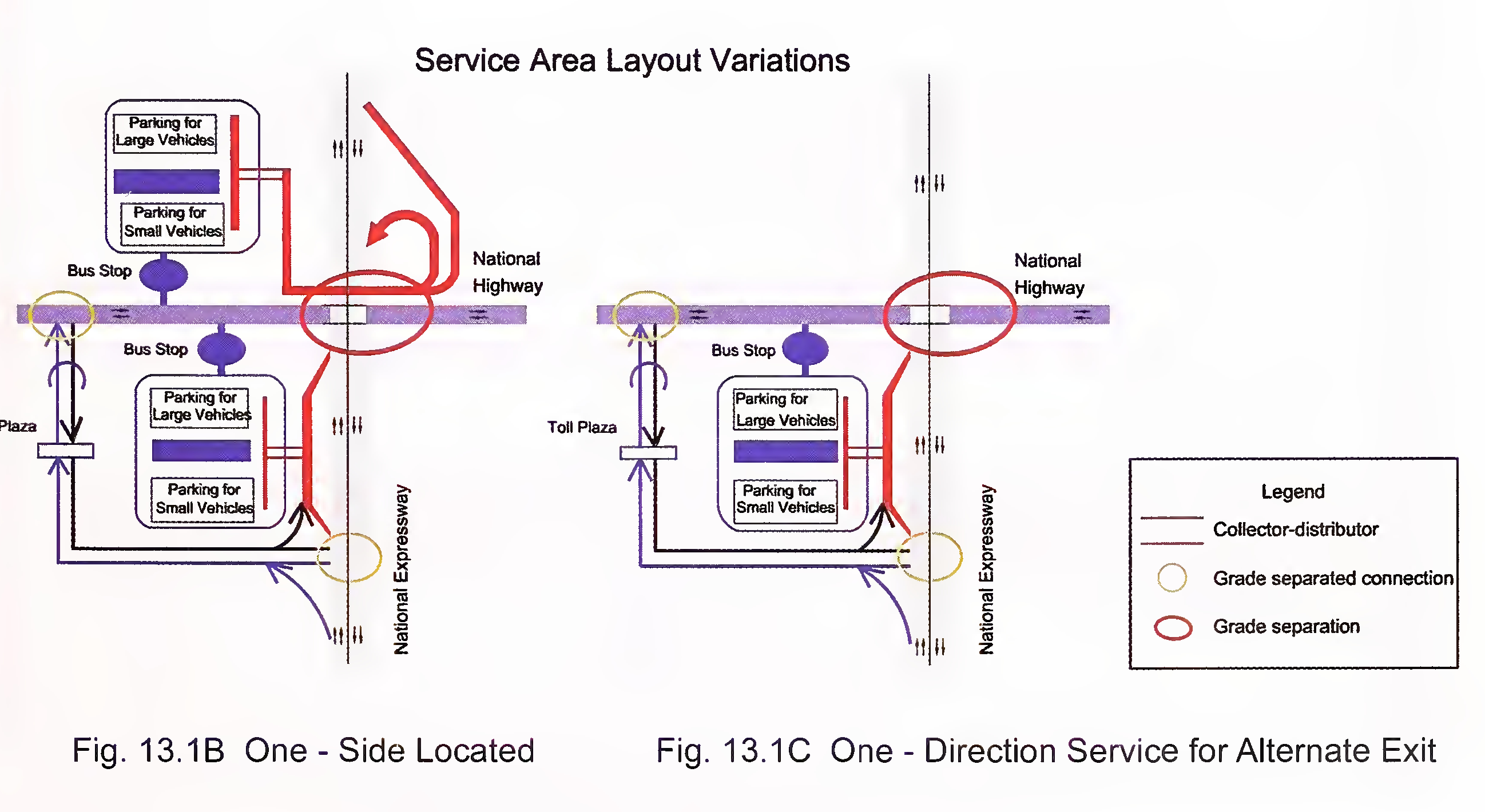 129
129
Typical Layout of Full-size and Small-size Amenities
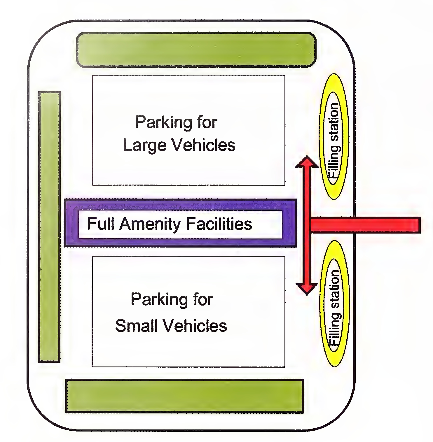
Fig. 13.1D Full-sized Amenity
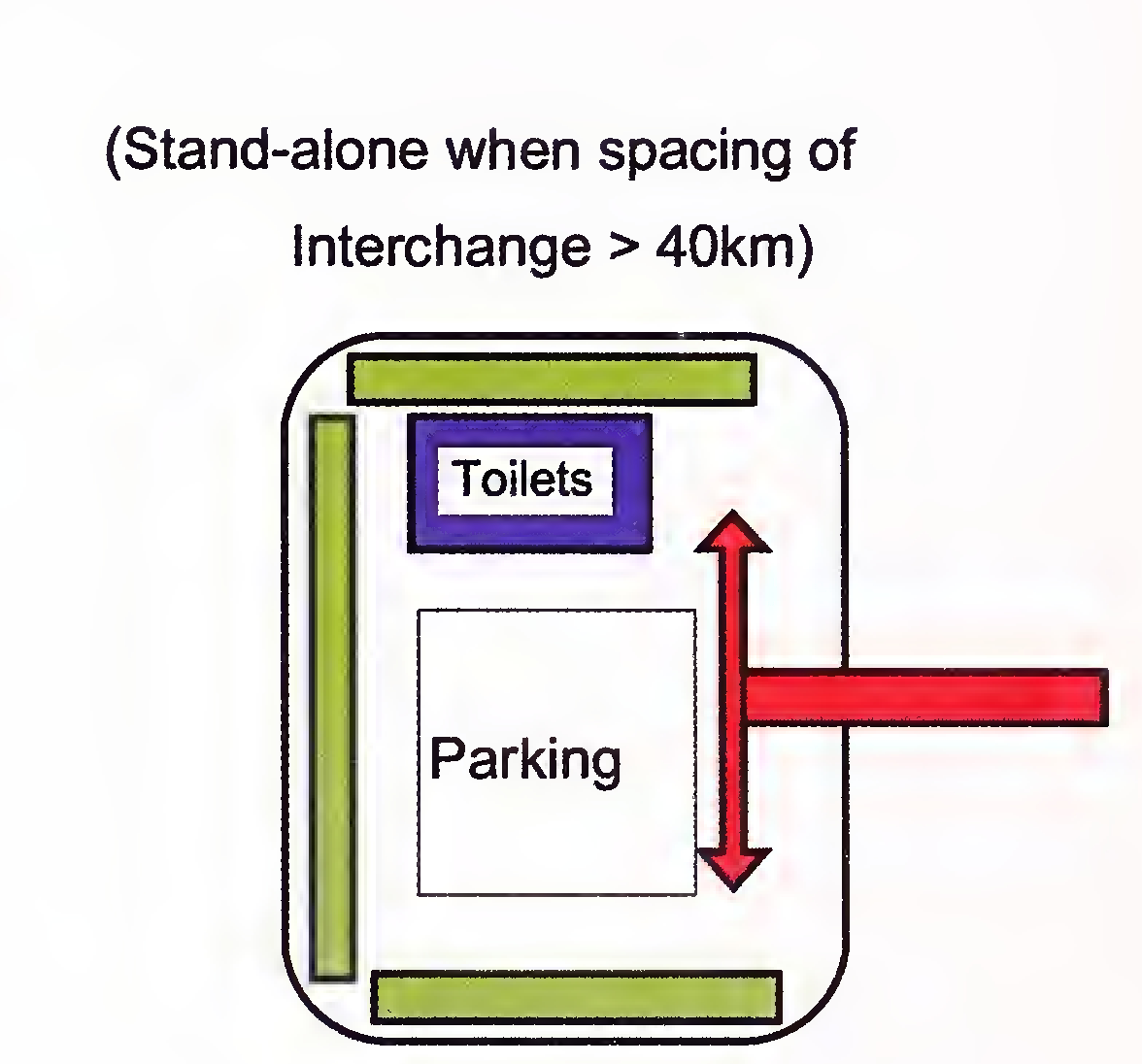
Fig. 13.1E Small-sized Amenity
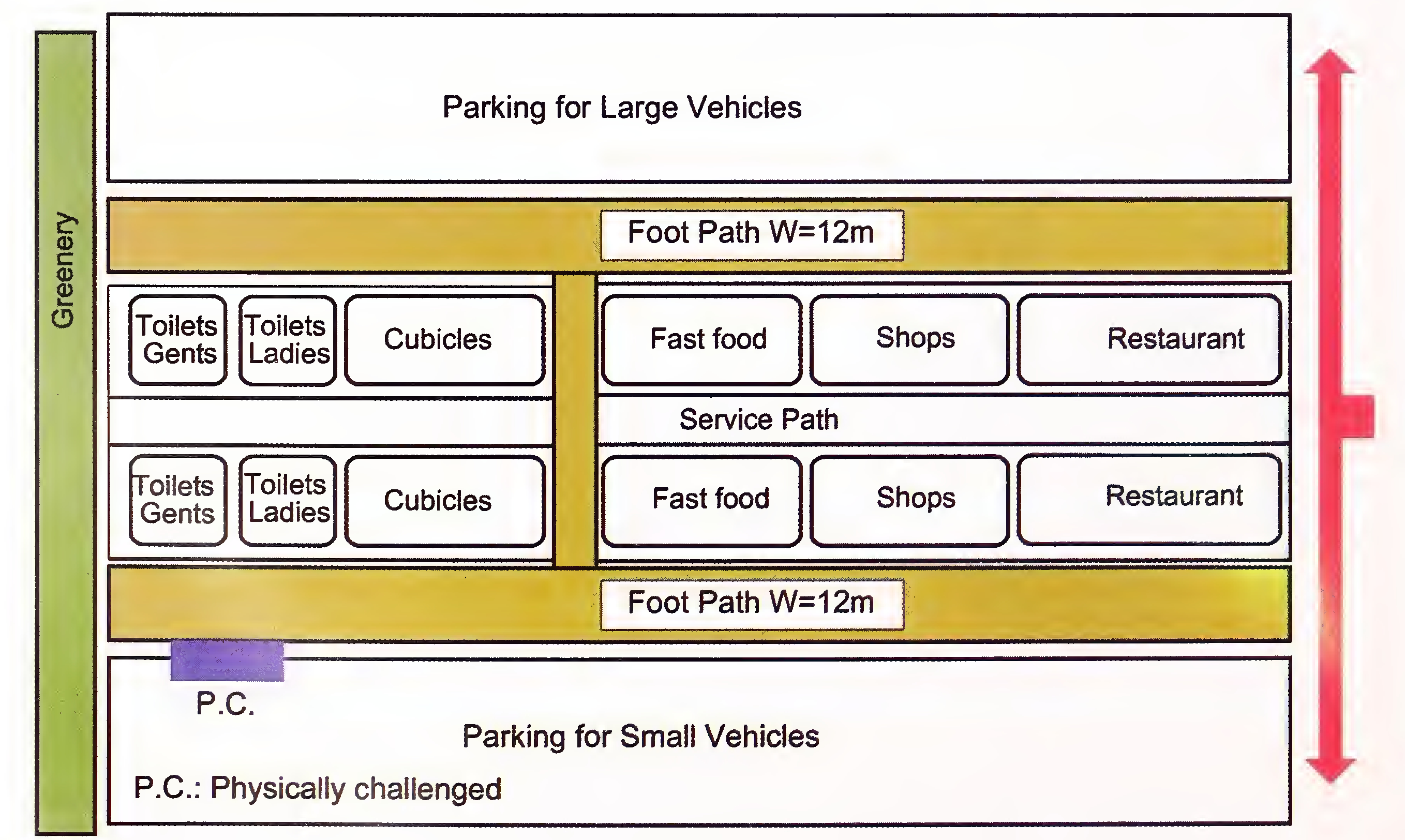
Fig. 13.1F Typical Layout of Service Areas130
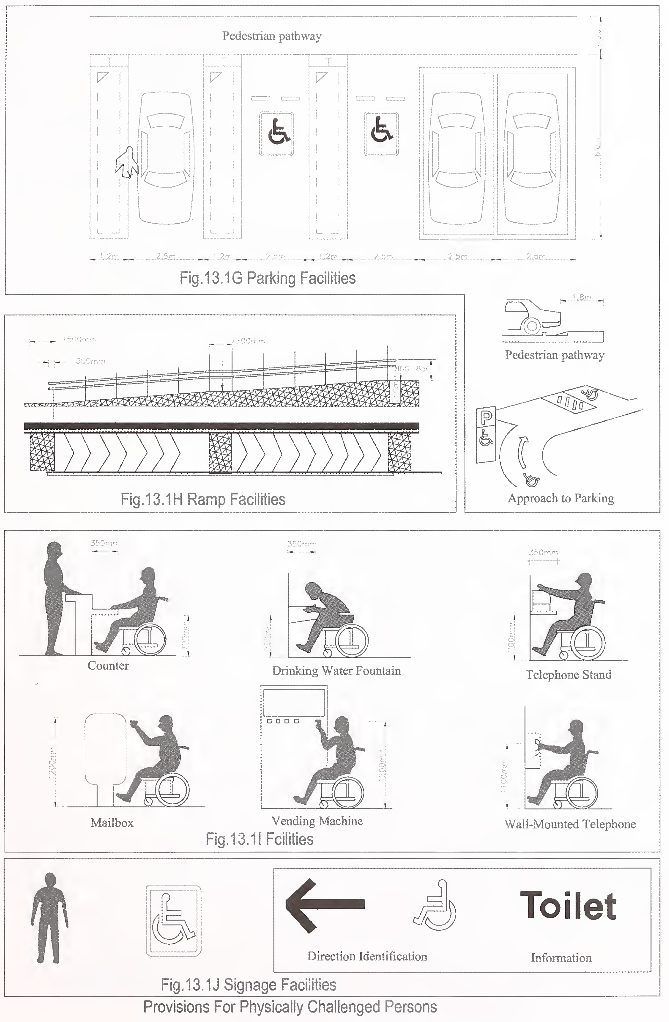 131
131
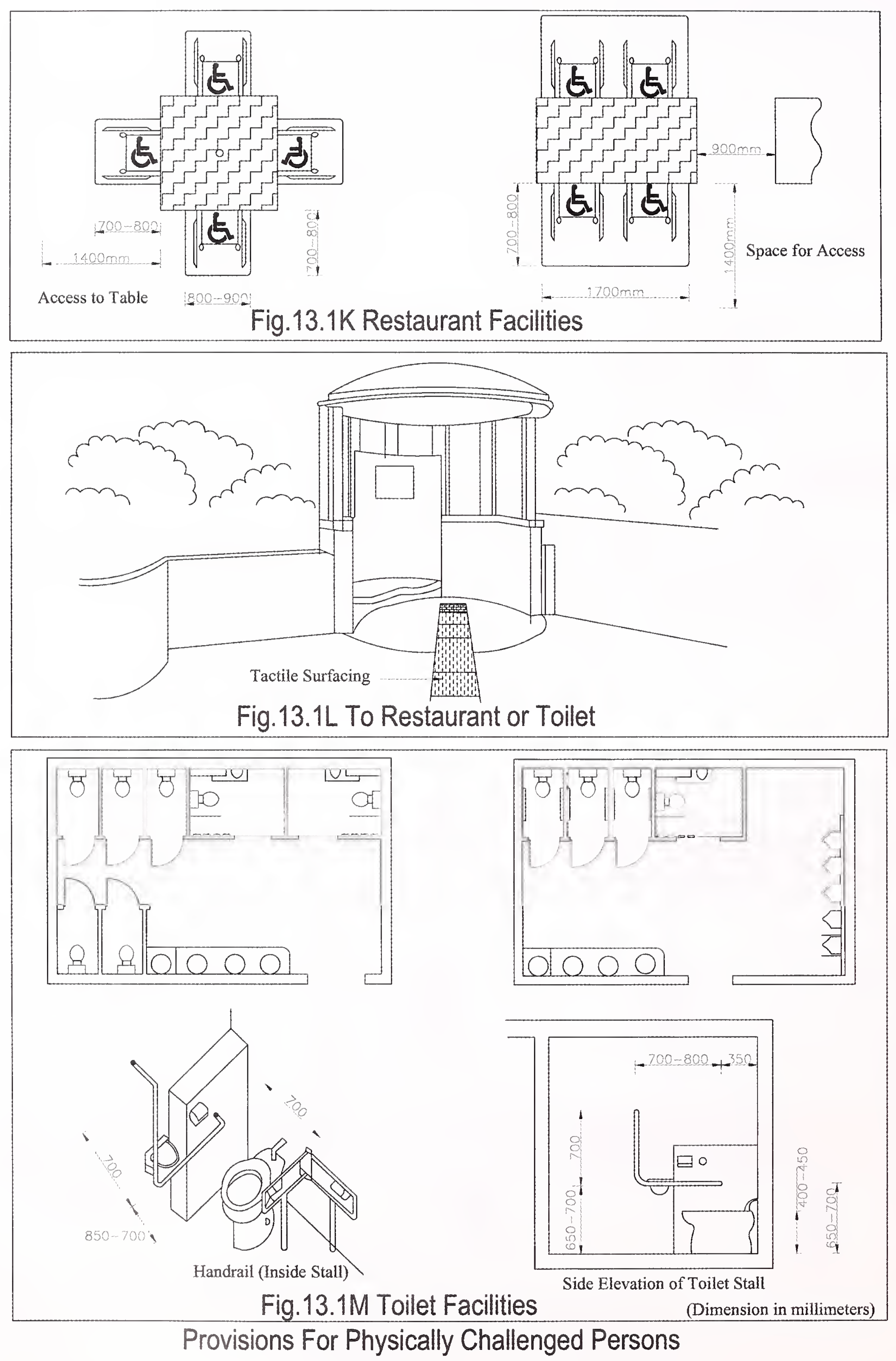 132
132
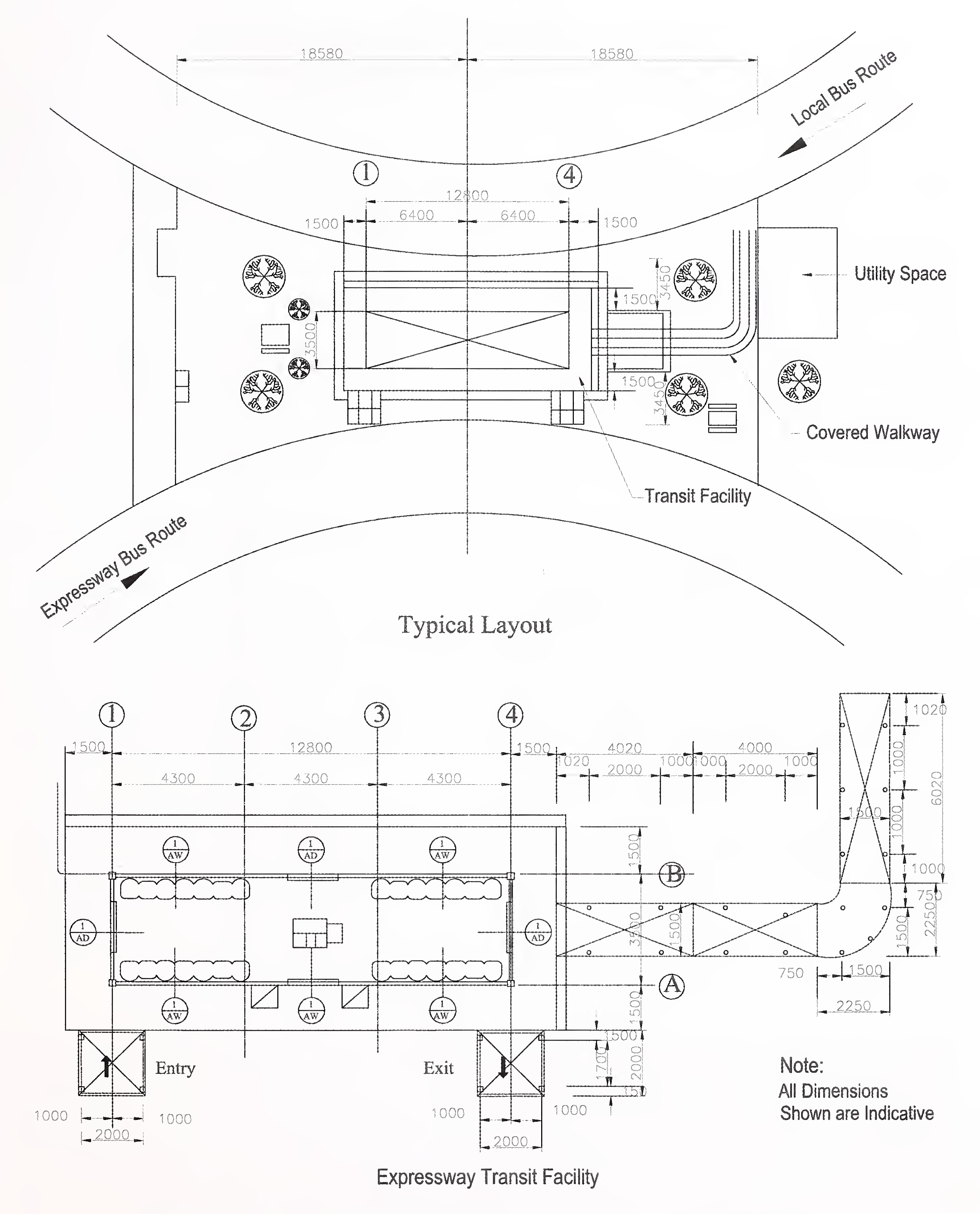
Fig. 13.2 Typical Functional Arrangement of Expressway Bus Route and Local Bus Route at Bus Stop.133
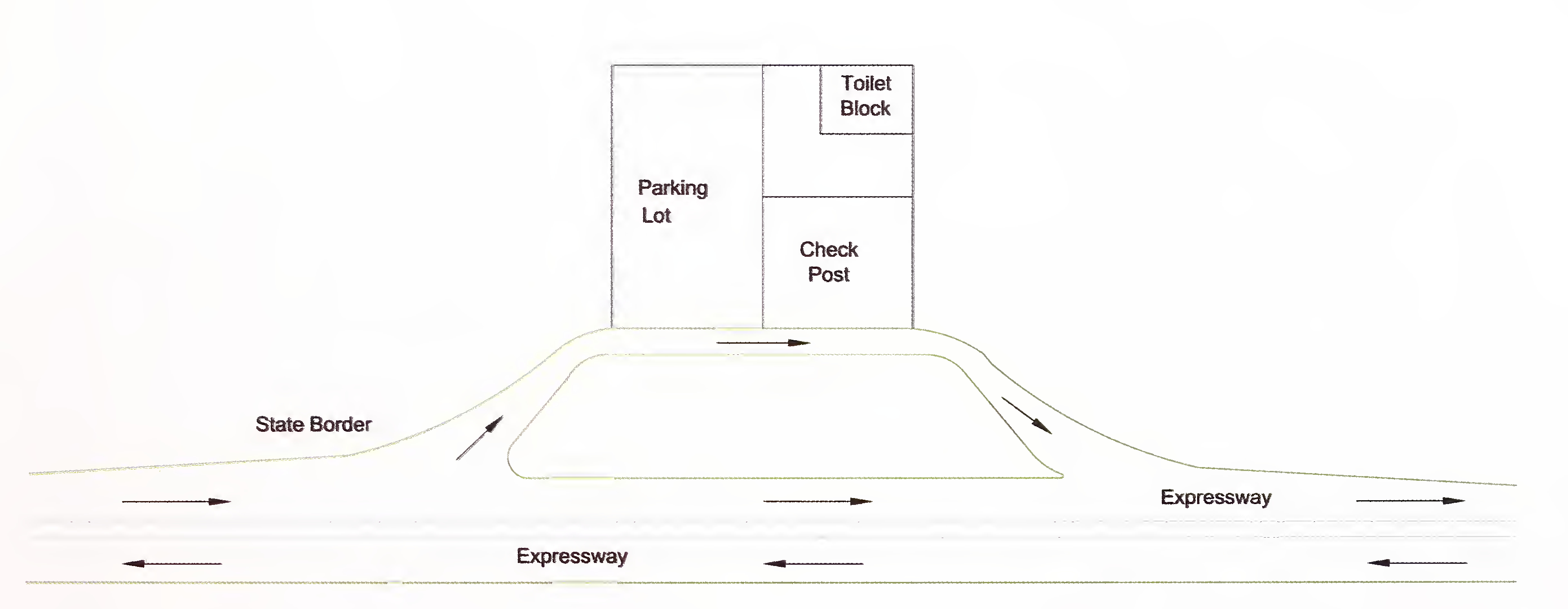
Fig. 13.3 Typical Layout of State Border & Entry Check Post134
Expressway projects are likely to be associated with some adverse environment impacts during construction, maintenance and operation stages. Significant impacts during construction relate to clearing, grading or road bed construction; loss of vegetative cover; foreclosure of land uses; property severance at community/individual levels; changes in natural drainage patterns; changes in ground water table, landslides, erosion, streams, ponds and lake sedimentation, degradation of cultural sites, interference with movements of wild life, live stock and local residents. Many of these impacts can arise not only at construction sites but also at quarries, borrow pits and material storage areas serving the Project Expressway. In addition, impacts can occur due to air and ground pollution from construction plants; dust from construction vehicle movements, noise from construction equipment and blasting, use of pesticides, fuel and oil spills, trash and garbage etc.
Many of the direct adverse impacts can be avoided/mitigated at the design stage. Accordingly while the Authority will seek the Environmental clearance for the Project Expressway from the relevant Ministries, Departments; the Concessionaire shall be responsible for implementation of Environmental Management Plan and action plan for undertaking possible mitigation measures in accordance with extant guidelines for highway projects of the Ministry of Environment and Forests (MOEF) and Wildlife Department of the Government of India.
The Authority shall make available to the Concessionaire, the list of conditions and directions stipulated by the MOEF at the time of giving their clearance for the Project Expressway and it shall be the responsibility of the Concessionaire to incorporate the same in its Environmental Management Plan referred to above.
The Concessionaire shall plant trees and shrubs of required number and type at the appropriate locations within the Right of Way and in the land earmarked by the Authority for afforestation keeping in view the IRC Guidelines on Landscaping and Tree Plantation. The Authority will specify the number of trees which are required to be planted by the Concessionaire as compensatory afforestation or otherwise in Schedule-C of the Concession Agreement. The Concessionaire shall also maintain the trees and shrubs in good condition during the Concession Period as per the maintenance schedule. Plantation shall be at the edge of the Right of Way.135
Trees on the roadside shall be sufficiently away from the roadway so that they are not a hazard to road traffic or restrict the visibility. Most vulnerable locations in this regard are the inside of curves, medians, entry/exit ramps and cut slopes. Trees shall be placed at a minimum distance of 14 m from the centre line of the left side paved shoulder to provide recovery area for the vehicle that runs off the road.
In the sections of the Project Expressway where median width is more than 3 m, shrubs shall be planted and maintained to cut off headlight glare from traffic in the opposite direction. Flowering plants and shrubs are eminently suited for the purpose. These shall be planted either in continuous rows or in the form of baffles. The height of shrubs shall be maintained at 1.5 m to cut off the effect of traffic lights coming from the opposite direction.
The shape of shrubs and plants shall be suitably regulated so that there is no overgrowth either vertically or horizontally beyond the edge of the paved median.
The spacing of avenue trees will depend on the type and growth characteristics of trees, requirement of maintenance, penetration of distant views, etc. A range of 10-15 m would meet the requirement for most varieties.
The following guidelines shall be kept in view while selecting the species of trees to be planted:
A suitable landscape treatment with provision of foundations and coloured lighting so as to enhance the overall aesthetics duly designed by a qualified and experienced landscaping architect, shall be provided at grade separators, elevated sections, viaducts, traffic islands, toll plazas, bus bays, truck lay byes, rest areas, O&M centre, etc. The locations where landscape treatment is to be given shall be specified in Schedule-C of the Concession Agreement. The landscape treatment shall also be provided for special areas as given in IRC:SP:21 (para 8).
The Concessionaire shall submit scheme for Environmental Management Plan (EMP) and for plantation and maintenance of plants and trees to the Independent Engineer for review and comments, if any.137
| Category | Average level | U0 | U1 | T1 |
|---|---|---|---|---|
| Expressways | 25 lux | 0.4 | 0.7 | 15% |
where,
U0: overall uniformity
U1: uniformity along the axis of the road
T1: maximum glare
The overall quality of an installation for lighting has several components:
Unless specified otherwise in Schedule-C of the Concession Agreement and elsewhere in this Manual, the Concessionaire shall provide lighting at the following locations of the Project Expressway.
Complete interchange lighting shall be provided on all the interchanges.
Lighting shall be provided inside the underpasses. The lighting of bridges and overpasses should be of the same level and uniformity as the roadway.
Tunnels require the use of lighting or equivalent means to provide adequate roadway and tunnel user visibility necessary for safe and efficient traffic operations. The tunnel lighting shall be designed as per MORTH Guidelines for Expressways, Chapter 13.5 Tunnel Lighting.
Toll Plaza Areas
The lighting in and around Toll Plaza, toll booths, office building, on the approach road, etc. shall be as per Section-12. Toll Plazas of this Manual.
Wayside Amenities
All Wayside Amenities offering facilities should be lighted, including the entrance and exit, the interior roadways, parking areas, and activity areas. Wayside Amenities include Rest Areas, Truck/Bus laybys, and Pick-up bus Stops. The lighting of Wayside Amenities shall be as per Section-13. Project Facilities of this Manual.
Other Specialized Areas
Lighting of other specialized areas should be considered with respect to the needs of the users as well as the requirements of others interacting with the users. These other specialized areas include truck weighing stations, inspections and enforcement areas, park-and-ride lots, toll plazas, and escape ramps.
The Concessionaire shall submit report containing the proposal for provision of Lighting on the Project Expressway to the Independent Engineer for review and comments, if any.140
Appendix - 1
(Refer Clause 1.4)
| SI. No. | Code/Document No. | Title of the Publication |
|---|---|---|
| 1. | IRC:2 | Route Marker Signs for National Highways |
| 2. | IRC:3 | Dimensions & Weights of Road Design Vehicles |
| 3. | IRC:5 | Standard Specifications and Code of Practice for Road Bridges, Section I - General Features of Design |
| 4. | IRC:6 | Standard Specifications and Code of Practice for Road Bridges, Section II - Loads and Stresses |
| 5. | IRC:8 | Type Designs for Highway Kilometre Stones |
| 6. | IRC:9 | Traffic Census on Non-Urban Roads |
| 7. | IRC:15 | Standard Specifications and Code of Practice for Construction of Concrete Roads |
| 8. | IRC:16 | Standard Specifications and Code of Practice for Prime and Tack Coat (Second Revision) |
| 9. | IRC:18 | Design Criteria for Prestressed Concrete Road Bridges (Post-Tensioned Concrete) |
| 10. | IRC:22 | Standard Specifications and Code of Practice for Road | Bridges, Section VI - Composite Construction (Limit States Design) (Second Revision) |
| 11. | IRC:24 | Standard Specifications and Code of Practice for Road Bridges, Steel Road Bridges (Limit State Method) |
| 12. | IRC:25 | Type Designs for Boundary Stones |
| 13. | IRC:26 | Type Design for 200-Metre Stones |
| 14. | IRC:30 | Standard Letters and Numerals of Different Heights for Use on Highway Signs |
| 15. | IRC:32 | Standard for Vertical and Horizontal Clearances of Overhead Electric Power and Telecommunication Lines as Related to Roads |
| 16. | IRC:34 | Recommendations for Road Construction in Areas Affected by Water Logging, Flooding and/or Salts Infestation |
| 17. | IRC:35 | Code of Practice for Road Markings |
| 18. | IRC:37-2001 | Guidelines for the Design of Flexible Pavements |
| 19. | IRC:37-2012 | Tentative Guidelines for the Design of Flexible Pavements |
| 20. | IRC:38 | Guidelines for Design of Horizontal Curves for Highways and Design Tables |
| 21. | IRC:44 | Guidelines for Cement Concrete Mix Design for Pavements |
| 22. | IRC:45 | Recommendations for Estimating the Resistance of Soil Below the Maximum Scour Level in the Design of Well Foundations of Bridges141 |
| 23. | IRC:56 | Recommended Practices for Treatment of Embankment and Roadside Slopes for Erosion Control |
| 24. | IRC:57 | Recommended Practice for Sealing of Joints in Concrete Pavements |
| 25. | IRC:58 | Guidelines for the Design of Plain Jointed Rigid Pavements for Highways |
| 26. | IRC:67 | Code of Practice for Road Signs |
| 27. | IRC:73 | Geometric Design Standards for Rural (Non-Urban) Highways |
| 28. | IRC:75 | Guidelines for the Design of High Embankments |
| 29. | IRC:78 | Standard Specifications and Code of Practice for Road Bridges, Section VII - Foundations and Substructure |
| 30. | IRC:83 (Part-I) | Standard Specifications and Code of Practice for Road Bridges, Section IX - Bearings, Part I : Metallic Bearings |
| 31. | IRC:83 (Part-II) | Standard Specifications and Code of Practice for Road Bridges, Section IX - Bearings, Part II: Elastomeric Bearings |
| 32. | IRC:87 | Guidelines for Formwork, Falsework and Temporary Structures |
| 33. | IRC:89 | Guidelines for Design and Construction of River Training & Control Works for Road Bridges |
| 34. | IRC:103 | Guidelines for Pedestrian Facilities |
| 35. | IRC:104 | Guidelines for Environmental Impact Assessment of Highway Projects |
| 36. | IRC: 107 | Tentative Specifications for Bitumen Mastic Wearing Courses |
| 37. | IRC: 108 | Guidelines for Traffic Prediction on Rural Highways |
| 38. | IRC: 111 | Specifications for Dense Graded Bituminous Mixes |
| 39. | IRC: 112 | Code of Practice for Concrete Road Bridges |
| 40. | IRC:SP:13 | Guidelines for the Design of Small Bridges and Culverts |
| 41. | IRC:SP:16 | Guidelines for Surface Evenness of Highway Pavements |
| 42. | IRC:SP:19 | Manual for Survey, Investigation and Preparation of Road Projects |
| 43. | IRC:SP:21 | Guidelines on Landscaping and Tree Plantation |
| 44. | IRC:SP:23 | Vertical Curves for Highways |
| 45. | IRC:SP:42 | Guidelines on Road Drainage |
| 46. | IRC:SP:47 | Guidelines on Quality Systems for Road Bridges (Plain, Reinforced, Prestressed and Composite Concrete) |
| 47. | IRC:SP:49 | Guidelines for the Use of Dry Lean Concrete as Sub-base for Rigid Pavement |
| 48. | IRC:SP:53 | Guidelines on Use of Modified Bitumen in Road Construction142 |
| 49. | IRC:SP:54 | Project Preparation Manual for Bridges |
| 50. | IRC:SP:55 | Guidelines for Safety in Construction Zones |
| 51. | IRC:SP:58 | Guidelines for Use of Flyash in Road Embankments |
| 52. | IRC:SP:63 | Guidelines for the Use of Interlocking Concrete Block Pavement |
| 53. | IRC:SP:69 | Guidelines & Specifications for Expansion Joints (First jRevision) |
| 54. | IRC:SP:70 | Guidelines for the Use of High Performance Concrete in Bridges |
| 55. | IRC:SP:71 | Guidelines for Design and Construction of Pretensioned Girder of Bridges |
| 56. | IRC:SP:80 | Guidelines for Corrosion Prevention, Monitoring and Remedial Measures for Concrete Bridge Structures |
| 57. | IRC:SP:83 | Guidelines for Maintenance, Repairs & Rehabilitation of Cement Concrete Pavements |
| 58. | IRC:SP-85 | Guidelines for Variable Message Signs |
| 59. | IRC:SP-88 | Road Safety Audit Manual |
| 60. | IRC:SP-89 | Guidelines for Soil and Granular Material Stabilization Using Cement Lime and Fly Ash |
| 61. | IRC:SP-90 | Manual for Grade Separators and Elevated Structures |
| 62. | IRC:SP-91 | Guidelines for Road Tunnels |
| 63. | IRC:SP-93 | Guidelines on Requirements for Environmental Clearance for Road Projects |
| 64. | IRC:- | Structural Evaluation and Strengthening of Flexible Road Pavements Using FWD (under print)143 |
Appendix - 2
(Refer Clause 1.11)
List of Paras for preparing schedules of the Concession Agreement (Refer Para 1.11)
| Section | Para | Particulars to be specified |
|---|---|---|
| Section 1 | 1.12(i) | Number of lanes to be providesd for the Project Expressway |
| 1.16 | Utilities to be constructed/shifted | |
| Section 2 | 2.3 | Right of way and land to be acquired |
| 2.5.1 | Type and width median in various stretches | |
| 2.9.2.3 | List of sections where radius of curve less than desirable minimum | |
| 2.10.1 | Width of underpasses | |
| 2.10.2 | Pedestrian and cattle underpasses where vertical clearance shall be 4.5 m | |
| 2.11.1 | Width of overpasses and span arrangement | |
| 2.12.2 | Location of interchanges | |
| 2.12.3 | Location and length of other details and specifications of connecting roads | |
| 2.13.1 | Location and other features of grade separated structures | |
| 2.13.2 |
(i) Type of structure for vehicular underpass or overpass and whether cross road shall be carried at the existing level or raised/lowered. (ii) Stretches where the Project Expressway shall be elevated or viaduct | |
| 2.13.3 | Location of light vehicle underpasses | |
| 2.13.4 | Location of cattle and pedestrian underpasses or overpasses | |
| 2.15 | Distance of fencing from the ROW boundary | |
| Section 3 | 3.1.1 and 3.2.1 | Location and type of grade separated structures, interchanges, other features and land requirements |
| 3.2.3 | Length of viaduct of grade separated structures | |
| Section 5 | 5.2.1 | Type of pavement |
| Section 6 | 6.1 (ii) | Provision of structures, initial configuration |
| 6.1 (vii) | Utility services to be carried over the structures144 | |
| 6.4 (iv) | Requirement of special structures like cable stayed/ superstructure bridge, etc. | |
| 6.4(v) | Span length of structures | |
| Section 7 | 7.1.3 | Requirement of Tunnel - Locations, length and number of lanes |
| Section 10 | 10.2.8 | Location and size of Over Head Signs |
| Section 13 | 13.1 | Location of Service Areas, Toilet Facilities |
| 13.2 | Location of Pick-up Bus Stops | |
| 13.3 | Location of Border Check Post | |
| Section 14 | 14.3.1 | Number of Trees to be planted |
| 14.4 | Locations for landscape treatment | |
| Section 15 | 15.1 (i) and 15.4 | Locations for providing lighting145 |
ANNEXURE
PERSONNEL OF PROJECT PREPARATION, CONTRACT MANAGEMENT & QUALITY ASSURANCE COMMITTEE (G-1)
| S.K. Puri | ..... | Convenor |
| P.K.Datta | ..... | Co-Convenor |
| K.Venkata Ramana | ..... | Member-Secretary |
| Members | ||
| A.K. Banerjee | K. Siva Reddy | Palash Shrivastava |
| A.K. Sarin | K.R.S. Ganesan | R.K. Pandey |
| A.P. Bahadur | L.P Padhy | R.S. Mahalaha |
| Ashok Kumar | M.K. Dasgupta | R.S. Sharma |
| Ashwini Kumar | M.P. Sharma | R. Chakrapani |
| Atar Singh | Maj. Gen K.T. Gajria | S.K. Nirmal |
| Col. A.K. Bhasin | N.K. Sinha | S.V. Patwardhan |
| D.P. Gupta Faqir Chand | P.R. Rao | Varun Aggarwal |
| Ex-Officio Members | ||
| Shri C. Kandasamy | Director General (Road Development) & Special Secretary, MORTH and President, IRC | |
| Shri Vishnu Shankar Prasad | Secretary General, IRC | |
| PERSONNEL OF THE ROAD SAFETY AND DESIGN COMMITTEE (H-7) | ||
| Dr. L.R. Kadiyali | ..... | Convenor |
| C.S. Prasad | ..... | Co-Convenor |
| Dr. Geetam Tiwari | ..... | Member-Secretary |
| Members | ||
| A.P. Bahadur | Manoj Kumar Ahuja | |
| Amarjit Singh | Prof. P.K. Sikdar | |
| B.G. Sreedevi | S.C. Sharma | |
| Bina C. Balakrishnan | The Addl. Director General of Police, Bangalore (Praveen Sood) | |
| D.P. Gupta | The Chief Engineer, (R) S, R&T, MORTH (Manoj Kumar) | |
| Dr. Dinesh Mohan | The Director, Gujarat Engineering Research Institute | |
| Dr. I.K. Pateriya | The Director, Quality Assurance & Research (formely HRS) | |
| Dr. Ravi Shankar | The Director, Transport Research Wing, MORTH | |
| Dr. S.M. Sarin | The Head, TED, CRRI (Dr. Nishi Mittal) | |
| Dr. S.S. Jain | The Joint Commissioner of Police (Traffic), New Delhi | |
| Dr. Sewa Ram | Yuvraj Singh Ahuja | |
| Ex-Officio Members | ||
| Shri C. Kandasamy | Director General (Road Development) & Special Secretary, MORTH and President, IRC | |
| Shri Vishnu Shankar Prasad | Secretary General, IRC146 | |