This library of books, audio, video, and other materials from and about India is curated and maintained by Public Resource. The purpose of this library is to assist the students and the lifelong learners of India in their pursuit of an education so that they may better their status and their opportunities and to secure for themselves and for others justice, social, economic and political.
This item has been posted for non-commercial purposes and facilitates fair dealing usage of academic and research materials for private use including research, for criticism and review of the work or of other works and reproduction by teachers and students in the course of instruction. Many of these materials are either unavailable or inaccessible in libraries in India, especially in some of the poorer states and this collection seeks to fill a major gap that exists in access to knowledge.
For other collections we curate and more information, please visit the Bharat Ek Khoj page. Jai Gyan!
IRC:SP:85-2010
Published by
INDIAN ROADS CONGRESS
Kama Koti Marg,
Sector 6, R.K. Puram,
New Delhi-110 022
MAY 2010
Price Rs 600/-
(Packing and Postage charges extra)
ABBREVIATIONS
| CMS | Changeable Message Sign |
| DMS | Dynamic Message Sign |
| PSA | Public Service Announcements |
| LDR | Light Dependent Resistor |
| LED | Light Emitting Diode |
| UV | Ultra Violet |
| VMS | Variable Message Sign |
| ms | Milli Seconds |
PERSONNEL OF HIGHWAYS SPECIFICATIONS & STANDARDS COMMITTEE (HSS)
(As on 20th October, 2003)
| 1. | Singh, Nirmal Jit (Convenor) |
Director General (RD) & Spl. Secretary, Ministry of Road Transport & Highways, New Delhi |
| 2. | Sinha, A.V. (Co-convenor) |
Addl. Director General, Ministry of Road Transport & Highways, New Delhi |
| 3. | Kandasamy C. (Member-Secretary) |
Chief Engineer ( R) S&R, Ministry of Road Transport & Highways, New Delhi |
| Members | ||
| 4. | Dhodapkar, A.N. | Chief Engineer (Plg.), Ministry of Road Transport & Highways, New Delhi |
| 5. | Datta, P.K. | Executive Director, Consulting Engg. Services (I) Pvt. Ltd., New Delhi |
| 6. | Gupta K.K. | Chief Engineer (Retd.), Haryana, PWD |
| 7. | Sinha, S. | Addl. Chief Transportation. Engineer, CIDCO, Navi Mumbai |
| 8. | Kadiyali, Dr. L.R. | Chief Executive, L.R. Kadiyali & Associate, New Delhi |
| 9. | Katare, P.K. | Director (Projects-III), National Rural Roads Development Agency, (Ministry of Rural Development), New Delhi |
| 10. | Jain, Dr. S.S. | Professor & Coordinator, Centre of Transportation Engg., NT Roorkee |
| 11. | Reddy, K. Siva | E-in-C (R&B) Andhra Pradesh, Hyderabad |
| 12. | Basu, S.B. | Chief Engineer (Retd.), MORT&H, New Delhi |
| 13. | Bordoloi, A.C. | Chief Engineer (NH) Assam, Guwahati |
| 14. | Rathore, S.S. | Principal Secretary to the Govt. of Gujarat, R&B Deptt. Gandhinagar |
| 15. | Pradhan, B.C. | Chief Engineer (NH), Govt. of Orissa, Bhubaneshwar |
| 16. | Prasad, D.N. | Chief Engineer (NH), RCD, Patna |
| 17. | Kumar, Ashok | Chief Engineer, Ministry of Road Transport & Highways, New Delhi |
| 18. | Kumar, Kamlesh | Chief Engineer, Ministry of Road Transport & Highways, New Delhi |
| 19. | Krishna, P. | Chief Engineer (Retd), Ministry of Road Transport & Highways, New Delhi |
| 20. | Patankar, V.L. | Chief Engineer, Ministry of Road Transport & Highways, New Delhii |
| 21. | Kumar, Mahesh | Engineer-In-Chief, Haryana, PWD |
| 22. | Bongirwar, P.L. | Advisor L&T, Mumbai |
| 23. | Sinha, A.K. | Chief Engineer (NH), UP PWD, Lucknow |
| 24. | Sharma, S.C. | DG(RD) & AS, MORT&H (Retd.), New Delhi |
| 25. | Sharma, Dr. V.M. | Consultant, AIMIL, New Delhi |
| 26. | Gupta, D.P. | DG(RD) & AS, MORT&H (Retd.), New Delhi |
| 27. | Momin, S.S. | Former Member, Maharashtra Public Service Commission, Mumbai |
| 28. | Reddy, Dr. T.S. | Ex-Scientist, Central Road Research Institute, New Delhi |
| 29. | Shukla, R.S. | Ex-Scientist, Central Road Research Institute, New Delhi |
| 30. | Jain, R.K. | Chief Engineer (Retd.) Haryana PWD, Sonepat |
| 31. | Chandrasekhar, Dr. B.P. | Director (Tech.), National Rural Roads Development Agency (Ministry of Rural Development), New Delhi |
| 32. | Singh, B.N. | Chief Engineer, Ministry of Road Transport & Highways, New Delhi |
| 33. | Nashkar, S.S. | Chief Engineer (NH), PW (R), Kolkata |
| 34. | Raju, Dr. G.V.S. | Chief Engineer (R&B), Andhra Pradesh, Hyderabad |
| 35. | Alam, Parvez | Vice President, Hindustan Constn. Co. Ltd., Mumbai |
| 36. | Gangopadhyay, Dr. S. | Director, Central Road Research Institute, New Delhi |
| 37. | Representative | DGBR, Directorate General Border Roads, New Delhi |
| Ex-Officio Members | ||
| 1. | President, IRC | (Deshpande, D.B.) Advisor, Maharashtra Airport Development Authority, Mumbai |
| 2. | Direcor General(RD) & Spl. Secretary | (Singh, Nirmal Jit) Ministry of Road Transport & Highways, New Delhi |
| 3. | Secretary General | (Indoria, R.P.) Indian Roads Congress, New Delhi |
| Corresponding Members | ||
| 1. | Justo, Dr. C.E.G. | Emeritus Fellow, Bangalore Univ., Bangalore |
| 2. | Khattar, M.D. | Consultant, Runwal Centre, Mumbai |
| 3. | Agarwal, M.K. | E-in-C(Retd), Haryana, PWD |
| 4. | Borge, V.B. | Secretary (Roads) (Retd.), Maharashtra PWD, Mumbaiii |
GUIDELINES FOR VARIABLE MESSAGE SIGNS
The purpose of these guidelines is to ensure that Variable Message Signs (VMS) messages are used to inform and direct motorists of variable situations in a consistent and orderly manner. The messages are for the purpose of traffic control, management and timely traveler information. It also has some basic requirements for design.
As with other traffic control devices, legibility, credibility and reliability of the message are critical. Without these basic requirements, even the best message will go unheeded. Care must be taken not to display a message that the motorists will not understand, disregard or will discover to be incorrect. Signs are the primary channels of communication to the motorists.
VMS is a valuable and effective traffic control device used to provide motorists en-route traveler information. The information is most often displayed in real-time and can be controlled either from a remote centralized location or locally at the site. VMS are designed to modify motorist behaviour to improve traffic flow and operations. Traveler information displayed on VMS may be generated as a result of a planned or unplanned event, which is programmed or scheduled by operations personnel. They are commonly installed on full-span overhead sign bridges, post-mounted on roadway shoulders, overhead cantilever structures and portable types mounted on trailers/ prime-mover.
Examples of traveler information provided through VMS include:
The objective of providing the information is to give travel directions and to enable the motorist adequate time to avoid an incident or prepare for unavoidable conditions. For all information displayed, the goal is to have a positive impact on the motorist's travel time.
VMS comprise of continuous and discontinuous signs.
Most VMS used for dynamic traffic management are of the discontinuous type, and make use of light emitting techniques (fibre optic or LED signs).
Generally, Variable Message Sign (VMS) systems form part of the Advanced Traffic Management System (ATMS), one of the major components of Intelligent Transport System (ITS). The Integrated ATMS software receives online data from Automatic Traffic Counter & Classifier (ATCC), Meteorological Sensors, Traffic Control System, CCTV, Video Incident Detection System (VIDS), Emergency Call Boxes (ECB), etc. After processing and analyzing the data, information can be automatically shared with the road users through VMS, Internet, SMS, FM, radio etc.
However, Variable Message Sign systems can also be used independently for providing information to the road users effectively. In this case, the inputs to the VMS systems are using manual entry or pre-programmed messages through computers.
This document was approved by the Transport Planning, Traffic Engineering and Road Safety Committee (H1) and Highways Specifications and Standards (HSS) Committee in their first meetings held on 13 April, 2009 and 06 June, 2009 respectively and then it was sent to IRC Council in its 188th Mid Term Council Meeting held at Kodaikanal. IRC Council referred back the document to H-1 Committee for some modifications. Modified document duly incorporating the comments offered by the Council Members was approved by the H-1 Committee in its third meeting held on 18 September, 2009. The modified draft document thereafter, placed before the HSS Committee during its second meeting held on 20 October, 2009 and HSS Committee approved the same. Draft document was approved by the Executive Committee in its meeting held on 31 October, 2009 was placed before the IRC Council in its 189th Meeting held at Patna on 14 November, 2009 for consideration. Council approved the document subject to some modifications in the light of comments offered by the Council Members. The Composition of the H-1 Committee is as given below:
| Sharma, S.C. | — | Convenor |
| Gangopadhyay, Dr. S. | — | Co-Convenor |
| Velmurugan, Dr. S. | — | Member-Secretary |
| Members | ||
| Basu, S.B. | Gupta, D.P. | |
| Bajpai, R.K. | Gupta, Dr. Sanjay | |
| Chandra, Dr. Satish | Kadiyali, Dr. L.R. | |
| Gajria, Maj. Gen. K.T. | Kandasamy, C.2 | |
| Kumar, Sudhir | Sikdar, Dr. PK. | |
| Mittal, Dr. (Mrs.) Nishi | Singh, Nirmal Jit | |
| Pal, Ms. Nimisha | Singh, Dr. (Ms.) Raj | |
| Palekar, R.C. | Tiwari, Dr. (Ms.) Geetam | |
| Parida, Dr. M. | Jt. Comm. of Delhi Police | |
| Raju, Dr. M.P | (Traffic) (S.N. Srivastava) | |
| Ranganathan, Prof. N. | Director (Tech.), NRRDA | |
| Singh, Pawan Kumar | (Dr. B.P Chandrasekhar) | |
| Rep. of E-in-C, NDMC | ||
| Ex-Officio Members | ||
| President, IRC | (Deshpande, D.B.) | |
| Director General (RD) & Spl. Secretary, MORTH | (Singh, Nirmal Jit), | |
| Secretary General, IRC | (Indoria, R.P) | |
| Corresponding Members | ||
| Bahadur, A. P. | Sarkar, J.R. | |
| Reddy, Dr. T.S. | Tare, Dr. (Mrs.) Vandana | |
| Rao, Prof. K.V. Krishna | ||
This document covers guidelines for design of Variable Message Sign for highways and urban roads. The intent of this document is to implement Intelligent Transport System in highway operation through deployment of VMS Signs. The document covers purpose of using VMS, warrants for VMS, message content of VMS, VMS for urban areas, portable VMS and design of VMS.
The Guidelines are broadly categorized into (i) Operational and (ii) Technical.
PART-A OPERATIONAL
The guidelines set forth the basic principles governing the use and design of VMS signs, and the messages should meet the following requirements:
Each VMS message shall be displayed for a specific purpose, such as, those provided in these guidelines. VMS shall not be used for advertising or public service announcement, VMS messages posted for roadway conditions or restrictions should be removed immediately when those conditions cease to exist or the restrictions are withdrawn. Identical conditions should always be given the same VMS message irrespective of where the conditions occur. Some examples of VMS are given in Annex-A.
The success of VMS depends upon the mechanism for collection and transmission of data on real time basis. Travel time between two destinations through a particular highway varies during different hours of the day. For display of this travel time, vehicle speed sensors need to be installed on the corridor. Also, there shall be a Control Centre where the data get assimilated, analyzed and distributed to the stake holders. Normally, input information to VMS are received in the Control Center from Emergency Call Boxes, Telephone/Mobile from road users/general public, Police, sensors like ATCC (Automatic Traffic Counter cum Classifiers), Meteorological System etc.
Variable Message Signs are used for the following purposes:
VMS can be used for lane and/or speed control purposes, and in most cases positioned over the traffic lanes e.g. lane change/closure/lane merge; speed funneling: speed harmonization, etc., by using speed indications.
VMS can be used for following warning messages.
Informative signs should use large text panels with two or three lines of text, sometimes accompanied by a pictogram. The picture/symbol will be more useful. For example Incident/ accident, Congestion/queue, Road closers, useful traffic information, and also Link messages (in future) may be displayed for information to motorists.4
The various situations when VMS will be appropriate are detailed below:
An incident with a minimum of blockage and with short time duration is not appropriate for a VMS warning. The situation will probably be cleared before the message is placed on the VMS.
Incidents that block lanes for substantial periods of time are ideal for providing information to the traveling public. Messages near the incident can inform motorists of the problem and move cars into side lanes. Signs location further away from the incident can suggest alternate routes.
Traffic is commonly diverted, such as when a road or pass is closed due to weather conditions, flooding, roadwork, major accident, and movement of oversized vehicles or movement of very important persons.
Regional, corridor-wise as well as project-wise incident management plans is to be developed to facilitate response to incidents and help mitigate traffic congestion. As directed by the Traffic and Safety Engineer/Project Manager, implementation of various levels of traffic management plans for incident management (i.e. use of pre-identified traffic detour routes) incorporate strategic use of VMS signs.
This warns motorists of on going or upcoming construction activities that will impact traffic flow. This may include lane closures, lane shifts, two-way traffic, shoulder work, and construction, traffic entering the highway, detours, etc. This will supplement normal signs required for roadworks and as provided in IRC SP: 55.
Messages will be used to display adverse weather or roadway conditions that may impact the drivers' visibility or safety. These conditions may include rains, flooding/water-logging, dust storms, snow, fog, falling rocks, mudslides, high winds, etc.5
Typically used in the tunnels and on toll plazas, these signs have a red 'X' in the closed lane and a green arrow in the open lane.
Probable time to reach the destination, Climatic conditions, Emergency number, General cautionary information like flood, Strike, Curfew, etc, in the areas nearby.
During initial VMS burn-in or during maintenance, test messages are a necessary function. These messages are for limited duration. But they are real messages with general purpose.
These messages display information about future events that affect traffic flow and safety. The messages should be displayed within a week of the event. In urban areas these messages shall be used only on through routes and high-speed corridors. There may be times where static signs would be more appropriate to use.
In general, Public Service Announcements (PSA) may be displayed on a limited and shortterm basis. The VMS should be used sparingly for the PSA so that the primary purpose and long-term efficacy of these signs will not be degraded. The PSA shall not be displayed in urban areas during the peak travel periods. Special event signing, notification of future roadway construction, are all forms of public service announcements while they are more for managing traffic, and have been addressed in previous sections.
However, there are additional categories of PSA messages appropriate for VMS use. Most PSA messages will fall into one of these categories, though there may be others, such as, non-typical truck load restrictions, natural disaster notification, and evacuation route information that would be appropriate as a PSA. Under no circumstances shall the VMS be used for advertising of any kind. The PSA shall not be displayed prior to the approval of the concerned authorities.
Messages related to driver safety campaigns will be allowed if other media is used, such as radio, TV, newspapers, billboards, etc. This is necessary since the message could be confusing to drivers if they have not been exposed to the information. In such cases the VMS should be used randomly, and sparingly. The total duration of display in these cases should not exceed two hours per day on any one-message board. The display times will be staggered,6
so the message will not appear at the same time each day, and care must be taken so the staggered times do not fall consecutively.
A VMS will be in a blank mode during the peak and off-peak periods when traffic, roadway, environmental, or pavement conditions, or public service announcements do not warrant the display of a message, or messages.
Variable Message Signs do provide a versatile means of communication for attending to a variable situation. The message, however, must be concise and clear for the drivers to interpret at high speeds while they can have any number of distractions. This section will illustrate how to write and display the message to give brief, clear and accurate information to the motorists. Each VMS board must be capable of displaying alphanumeric characters in English, Hindi and local language. Pictorial signs already available for regular traffic signs can be useful as variable message sign.
The reading time is the time it actually takes a driver to read a sign message. The exposure time is the length of time a driver is within the legible distance of the message. So the exposure time must always be equal to or greater than the reading time. Depending upon the speed of the drivers, the message length must be adjusted to ensure the reading time can fit into the exposure time.
The aim should be to have minimum legibility of portable variable message signs at 300 m for expressway and 200 m for other roads. Table 1 gives the time in seconds, it takes to travel 300 m at various speeds.
| Speed (km/h) | Time (Seconds) to Travel 300 m |
|---|---|
| 50 | 21.6 |
| 70 | 15.4 |
| 90 | 12.0 |
| 100 | 10.8 |
| 120 | 9.0 |
It is, however, recommended that the size and distance for clear legibility should be designed for at least 15 seconds for NH and 20 seconds for access controlled expressways. Further more, the messages need to be displayed alternately in HINDI (or Local Language) and 'ENGLISH' if not possible pictorially as well. The board having the facility to display minimum7
of 2 lines of 12 or 15 English characters, can have English display in 1st line and other language in 2nd line, at the same time as well.
When the VMS displays a series of message, 2-4 seconds per message is recommended. The blinking feature may be used on one or more of the messages. It should, however, not be used for more than one line of each message.
Table 2 shows the maximum number of message panels that can be displayed for each speed limit, provided there is at least 300 m of sight distance.
| Speed Limit (km/h) | Number of Message Panels | |
|---|---|---|
| 70 | 3 | (see "Limit Panels" section) |
| 90 | 3 | - do - |
| 100 | 2 | - do - |
| 120 | 2 | - do - |
If only one message is used, the sign may be at steady burn and the blinking feature may also be used for a single message. For example, the single message may also be ON for 2 seconds and OFF for 1 second.
For 120 km/h according to the various standards the letter size should be minimum 400 mm for English Alphabet and 380 mm for any other local script excluding the vowel connotations (manufacturer at his choice may use full matrix instead of line matrix to fulfill vowel display requirement).
The limitations to the number of message panels to use are two fold:
A sample list of VMS messages are given in Annex-B.
In each message there are units of information. A unit is one separate piece of data that the driver can recall and use to make a decision. A unit normally is one or two words but can be up to four words long. For example, the following message has four units of information.
| What happened? | ......ROAD CLOSED |
| Where? | AT EXIT XX TO DELHI |
| Who is affected? | ALL TRAFFIC |
| What must they do? | MUST USE ALTERNATE ROUTE |
Another example could be as follows:
The message-load for the above is 4 units, that is reaching the limit for an average person to understand while traveling at a high speed. The message length is the number of words or characters in the message. The average motorist traveling at a high rate of speed can handle 8 word messages of 4 to 8 characters per word, (excluding prepositions). The number of panels or frames is another important variable in the construction of a clear message.9
Message familiarity is another aide for motorist's ability to understand a message. When information displayed to motorists is unusual, longer comprehension time is required. Common language is necessary.
For message comprehension, the following are suggestions taken from research conducted by the developed countries concerning messages, drivers can comprehend the quickest:
Experience has shown there are three types of elements to use when messages fall under the categories of incidents and traveler information, as follows:
The advisory signs, display real-time information about highway status and advises concerning the best course of action. These will mostly be used for incidents. The advisory sign message should consist of the following:
The minimum information is the problem and action statements. The location of the problem is also sometimes useful in a diversion decision.10
Guide signs are necessary if the traffic must be diverted due to an incident or construction. The guide signs must provide destination information and route affirmation and direction.
There are times to inform drivers of incidents that are further ahead of the current location. This up-to-date information has the following basic elements that can be communicated:
If there is a diversion situation with known alternative routes available:
The location of the equipment shall be strategically placed to:
The display background shall be non-reflective. There are 3 types of displays:
The system must be in three languages, able to display English, Hindi and Regional Language.
Equipment shall be placed off-shoulder (pole mounted) and clear of the traffic and any emergency lane and position shall be determined so that extraneous effects, such as, direct sunlight are negated. Lateral placement of VMS shall be guided by the provisions for fixed signs.
The above guidelines apply to all types of VMS, but because of its nature, the following additional guidelines are applicable to the portable VMS.
The location of the equipment shall be strategically placed to:
Equipment shall be portable and will be installed on the vehicle (Crane/Trolley mount).
Text displays shall be capable of displaying 2 lines of text characters. There shall be a minimum of 10 characters per line. Minimum default character height shall be 300 mm. For variable font height, FONT generator module is to be provided wherein user can create bmp files and later convert to image file to preview and display on required VMS. The sign panel display shall be legible from a distance of at least 200 m.
Each LED to be separately encapsulated in a round lens.
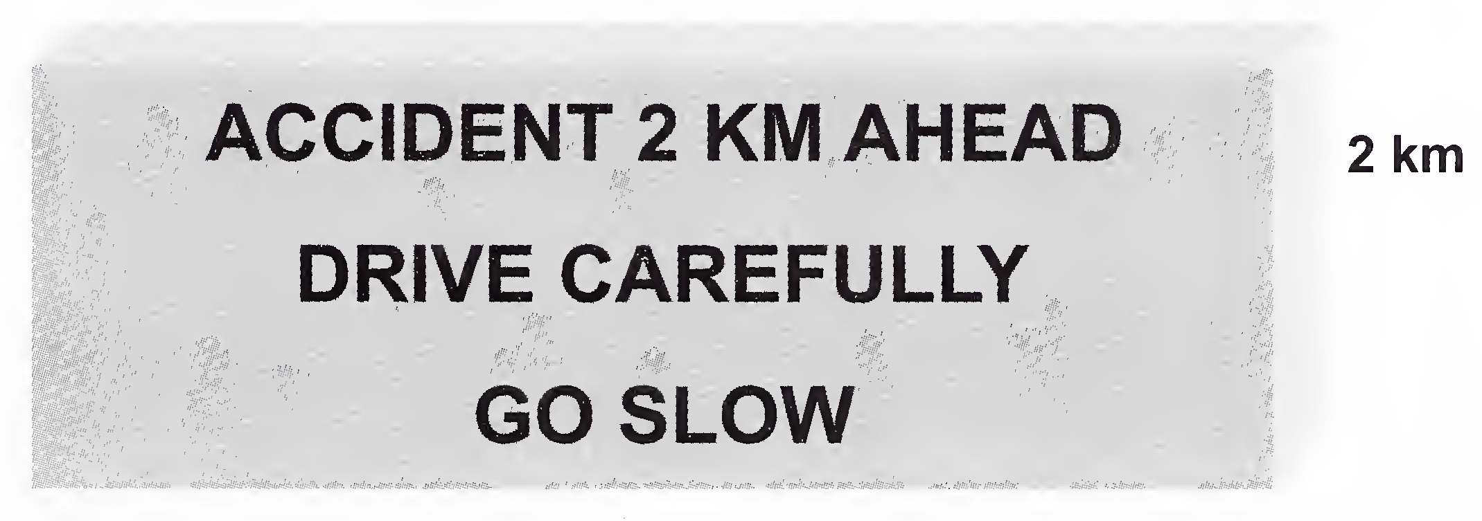
The proper placement of a portable VMS is critical to its effectiveness. The placement requirement must give the motorist adequate time to react to the message. The VMS must be located prior to major decision points, such as intersections or interchanges, where the driver may change their travel plans. On National Highways, or other access-controlled freeways, placement 2 km prior to the interchange /exit is recommended, and must be repeated at every 500 m and also it must be placed 50 m prior to the point of decision.
Placement requirements include:
To provide 200 m of sight distance.
If more than 2 VMS are to be used in sequence, they should be separated by at least 300 m. The sign should be placed off the shoulder of the roadway, behind the crash barrier, if possible, and where it will be accessible to maintenance vehicles even if the traffic queue develops or grows.
To be comfortable to read, the VMS panel should be turned slightly towards the driver's view, at approximately 5 to 10 degrees from perpendicular of the road's centerline. Reading the VMS becomes more difficult as the angle is increased from the normal field of vision. It is recommended to test check the VMS after installation by driving along the road to be sure that the message on the sign can be read from the road.13
If the portable VMS is set up along the roadway and a message will not be needed for a period of next 4 hours or more, the sign panel should be turned away from traffic, parallel to the road's centerline. No blank signs should be facing the drivers for extended periods.
PART-B TECHNICAL
The sign part of the VMS system shall consist of a sign housing, optical systems, internal wiring, controller system and related equipment, terminal strips for interconnecting wire, etc.
Any electronic or electrical device installed in the housing shall be mounted for easy access for maintenance personnel. The VMS System shall be modular in design so that it is not necessary for a technician to remove or replace discrete components in the field to analyze and/or correct a failure.
All front face windows and access doors shall be sealed or gasketed to prevent water, dirt and insects from entering the interior. Screened ventilation louvres and drains shall be included to eliminate moisture buildup due to condensation.
VMS shall operate continuously within the temperature range of -34°C to +65°C. The transfer and absorption of heat due to solar radiation shall be minimized by the design of the housing and front face. This design also helps minimize the power consumption and maintenance needs and maximize the operability and longevity of the sign.
The VMS controller shall monitor all the temperature and humidity sensors and perform the proper action when required. Temperature and humidity sensors shall be solid state. Heaters shall be used to control moisture and to prevent condensation (i.e. frost, snow, ice, etc) from accumulating on the front face.
If the temperature reaches a specific threshold (+65°C), it should be automatically switched off for safety reasons.
All front face panel surfaces not directly in front of a light emitting pixel shall be masked with a black material to reduce glare and increase the contrast ratio. All light emitting pixels shall14 be protected by the use of a polycarbonate face that shall prevent the entry of water, dust, dirt and insects. All pixels shall be designed in such a manner to eliminate reflective ghost effects from sunlight shining onto the front of the pixel. An aluminum mask shall be utilized in front of the polycarbonate window to shade the LED pixels from the sun.
The housing shall prevent any light leaks or reflection from:
The housing of the VMS must be based on modular design.
The front of the sign housing shall be surrounded by an aluminum contrast shield to improve legibility. This shield shall be bolted to the sign or be an integral part of the sign housing and shall mate so that no light leaks occur.
The contrast shield shall be covered by the same black protection as the front face. No difference in color shall be visible by the motorist between the front face and the contrast shield.
The VMS housing shall be built to guarantee structural integrity and shall comply with the Standard Specifications for Structural Supports for Highway Signs, Luminaires, and Traffic Signals.
The structural members of the VMS Sign Housing shall use an aluminum alloy. The housing must be made of aluminum extrusions that are welded or assembled together. The structural framing members shall be welded for a walk-in housing. Other sign access types that utilize extrusions as the structural members shall be bolted together using stainless steel and aluminum hardware.
To minimize heat build up, the back, top, bottom and sides shall have a maintenance free natural aluminum finish.15
If necessary due to the road configuration, each VMS may as an option have the ability to adjust the tilt of the entire sign housing (and front face), from 0° to 10°, in one-degree minimum increments, to properly aim and orient the sign to the roadway.
Any access panels shall be limited in size so they may be opened or closed by one person only and shall be gasketed and sealed to prevent the elements from entering (when closed) and shall include locks to prevent unauthorized access. Access panels shall be supported in their open position by multiple self-locking retaining devices that thoroughly support the panel assembly in the open position in 64 km/h wind.
Several access are possible and should be defined on project basis. It is important to define the VMS access in accordance with the design of the supporting structure in order to insure that the mounting arrangement is adequate and possible.
The VMS enclosure provides a walk-in access. Walkways along the support structure shall be provided. Walk-in housings shall allow access to all components from within the sign.
A non-skid aluminum floor shall be provided, so that a maintenance person can walk to either end of the interior with a constant minimum of 61 cm (24-inches) of aisle space to perform his duties.
For the safety of motorists as well as maintenance teams, the following safety equipment shall be provided:
A door handle shall be provided outside and inside the housing so that a person with no key or no tools cannot be trapped inside the housing.
Light Service:
A minimum of one 60W fluorescent light every 2.40 m of housing shall be provided.
Walk-In Access Door:
The sign shall have one access door, which shall be rain, insect and dust-tight and shall open outward. A stop mechanism shall be provided to keep the door in the open (90°) position. When open, the door shall be sturdy enough to withstand wind gusts of 64 km/h and not be deformed. The door shall be equipped with a proper latching system. A door handle must be provided outside and inside the housing so that a person with no key or no tools cannot be trapped inside the housing.16
A door switch shall be provided and wired to the VMS controller so that the position of the door (open or closed) can be monitored. This information shall be transmitted to control center upon request.
Walk-In Work Area :
The dimension of a non-obstructed interior walkway must be a minimum of 61 cm wide and 180 cm or 1.8 m high and the structural members shall not obstruct any movement of technicians inside the work area.
The sign floor shall be designed to avoid water retention. A minimum of four drainage holes, designed to prevent the entry of insects and the accumulation of dirt and moisture, shall be provided.
Walk-In Light Service:
A minimum of one 60 W fluorescent light every 2.40 m of housing shall be provided. The light assembly shall be protected by a cage. A manual timer having a maximum ON time of two hours must control all lights and must be placed near the entry door so the light will automatically be switched off. It is noted that no maintenance can be done without internal light system as it will be impossible to see the electronic equipment.
For signs greater than 183 cm high, the access doors shall be hinged at the top and at some other intermediate point, so that when the access doors are in the open position, they shall create a temporary shelter that consists of a roof and partial rear wall.
Mounting Structure shall use minimum 5.5 m high hexagonal/octagonal MS pole (minimum 300 mm diameter and 5 mm thickness) with minimum 520 mm × 520 mm × 16 mm base plate (with sufficient stiffeners). It shall be painted with one coat of primer and two coats of PU paint. Structure shall be provided with suitable stiffeners and support angles to survive wind speed upto 150 km/h.
The minimum vertical clearance under the sign shall be 5.5 m to the road surface.
The VMS Sign, the VMS controller, and any interface cabling between the sign and controller shall be considered as one closed system regardless of where the VMS controller is installed relative to the sign. The protocol and command set between the sign controller and VMS sign shall be entirely independent of and not interfere with any communication protocol or command set used to communicate to the control center or any remote devices such as a laptop or wireless system.
Terminations for the wiring between the VMS Sign and the VMS Controller cabinet shall be made on screw clamp terminal blocks located at one location within the VMS Sign Housing.
The VMS display board shall use high intensity light emitting diode (LED) to display alphanumeric messages. LEDs are grouped, mounted on a special holder or on a PCB to form a pixel. The number of LEDs per pixels is defined by the manufacturer to achieve the luminance requirements defined within this document. Each character is displayed by lighting up the relevant pixels. Pixel size can be 15 to 22 mm as per design of manufacturer while pixel pitch (centre to centre distance of 2 adjacent pixels) should be 22 mm to 25 mm depending on pixel size and character sizes.
Each character has a minimum height of 400 mm +/- 20 mm. English character in 7x5 (HxW) aspect ratio and thus character height has to be in multiple of 7x5 matched as per pixel pitch. 14 pixels at Min. 22.5 mm pixel pitch gives 315 mm and 21 pixels gives 472 mm The spacing between 2 characters in the horizontal direction should be 2S and spacing between 2 lines is min 4S.18
S is derived as under,
S = 1 Stroke = 1/7(character height).
The optical system shall provide a uniform display across the sign, so that there is no visible difference in luminous intensity from any one pixel to another pixel, under any brightness level.
The luminance intensity (also called luminosity) shall be measured at the front of the sign in its final position with any component that could impede or otherwise affect the light output (such as the front face, mask, and polycarbonate) in place.
The VMS supplier shall submit a test certificate from an independent laboratory/Agency to certify that the luminance intensity is at least 12,000 cd/m2 under 40,000 Lux. The luminance intensity shall be measured at the front of the sign in its final position with any component that could impede or otherwise affect the light output (such as the front face, mask, and polycarbonate) in place.
Luminous Intensity Uniformity
The ratio between the brightest pixel and the less luminous pixel shall be less than 3:1 when measured at the front of the sign with all components in place.
The board shall be designed for automatic adjustment of the display brightness (LED Intensity) to the ambient light based on Light dependent resistor (LDR).
The display shall change from one page of text to another in less than 100 ms. Changes from one message to another shall take place so that the motorist visualizes only the complete and intended message on the sign face, at any one time. No other message interpretations other than the intended message shall be possible during transitions from one message to another. All lines of text shall energize and de-energize simultaneously.
VMS should have following features.
LED Light System
All LEDs used in a sign shall come from the same LED component manufacturer and shall be non-tinted, non-diffused, high intensity.
The minimum operating temperature range of the LEDs, as defined by the LED manufacturer, shall be -40°C to +85°C.
A cabinet shall protect all the electronic components and the controller. This cabinet shall be mounted on floor near the VMS or on the supporting pole.
The cabinet shall be made of aluminum and shall comply with IP55 protection.
The cabinet shall include the following:
Permanently Mounted Document Holder
A pullout shelf for the placement of a laptop computer, provided and stored within the cabinet.20
The controller is the main intelligent unit of the VMS. It shall be 19-inch rack mounted microprocessor based VMS Controller (CPU).
The VMS Controller shall be capable of full operations, without the need for an external modem or signal booster when the VMS Controller is located upto one kilometer from the sign.
The controller shall be capable of receiving 12V DC from a battery, in order to provide extended operation time in the event of a power failure. The controller shall be capable of charging the battery.
The VMS Controller shall include a Central Processor Module having a battery backed clock calendar to record power failures and to perform all calculations and logical functions of the VMS Controller.
One VMS Controller shall be capable of operating multiple VMS.
The VMS Controller shall include one integrated Digital I/O board with 4 inputs and 4 outputs. Additional boards can be added external to the controller.
The VMS Controller CPU shall be at least a 32-bit processor which operates at 400 MHz or greater. It shall have at least 20 MB of SRAM, and be capable of expanding its memory at least 16 MB more, via use of an industry standard "FLASH" memory card.
VMS Controller shall have the ability to control a TFT color screen with keypad, for local diagnostics and control of the sign. Screen and keyboard shall be at the front of the controller.
The VMS Controller shall continuously monitor the display of the sign, independent of any external commands, and shall cause the signs to display all the appropriate characters.
The VMS Controller shall command the sign to display characters and messages by turning the LED's on and off. In addition, it shall accumulate data about the status of the sign (to be transmitted upon request), and shall receive commands from the Central Computer and Portable Maintenance Computer.
Each VMS Controller shall be uniquely addressable from the Control Centre via the communication system for control and monitoring. The communication profiles that must be21
supported by the controller are:
PMPP - NULL, PPP - NULL, Ethernet - UDP/IP, RS-232
The VMS Controller shall be capable of communicating using NTCIP or other equivalent international protocols.
The VMS electronics is protected against high voltage surges coming on the field cables, by using appropriate surge arresters. Suitable earthing (maximum 3 Ohms earthing resistance) is provided by using separate conductor for earth.
Each individual VMS shall be able to store all the required data for displaying information locally. The equipment shall be capable of storing minimum 20 frames that can be triggered on receiving the command.
Data Communications may be through any of the links like Dedicated line, Leased line from the local service provider, GSM/CDMA- DATA channel, GSM/CDMA- SMS channel.
Data communication shall be provided with sufficient security check to avoid unauthorised access.
attributes like message blink, message blank, and message entry styles (Left, Top Bottom entry).
VMS shall be powered by 230 V AC, 50 Hz single phase power supply. The equipment components shall have adequate surge and lightning protection.
In case of power failure, Inverter of adequate power capacity having 6 hours back up will be provided.
The minimum design life for the equipment before replacement shall be 10 years.
The central control computer shall be capable of setting an individual VMS, or group of VMS, to display either one of the pre-set messages, or symbols, or a text message. In addition, the central control computer system shall be capable of being programmed to display an individual message on a VMS, or group of VMS, at a pre-set date and time. A sequence of a minimum of 10 messages/symbols per VMS shall be possible.
The central control computer shall also store, in a suitable database, information about the messages displayed on each VMS. The minimum information to be stored shall be:
The central control computer shall test each individual VMS on a regular (pre-set) basis. This test should be exhaustive and determine if the system is fully operational.23
Each individual VMS shall be able to store all the required data for displaying information locally. The equipment shall be capable of storing minimum 10 frames that can be triggered on receiving the command.
Equipment shall be portable and will be installed on the vehicle (Crane/Trolley mount).
The proper placement of a portable VMS is critical to its effectiveness. The placement requirement must give the motorist adequate time to react to the message. The VMS must be located prior to major decision points, such as intersections or interchanges, where the driver may change their travel plans. On National Highways, or other access-controlled freeways, placement 2 kilometres prior to the interchange/exit is recommended, and must be repeated at every 500 m and also it must be placed 50 m prior to the point of decision.
Placement requirements include:
If more than 2 VMS are to be used in sequence, they should be separated by at least 300 m. The sign should be placed off the shoulder of the roadway, behind the crash barrier, if possible, and where it will be accessible to maintenance vehicles even if the traffic queue develops or grows.
To be comfortable to read, the VMS panel should be turned slightly towards the driver's view, at approximately 5 to 10 degrees from perpendicular of the road's centerline. Reading the VMS becomes more difficult as the angle is increased from the normal field of vision. It is recommended to test check the VMS after installation by driving along the road to be sure that the message on the sign can be read from the road.
If the portable VMS is set up along the roadway and a message will not be needed for a period of next 4 hours or more, the sign panel should be turned away from traffic, parallel to the road's centerline. No blank signs should be facing the drivers for extended periods.
Line matrix signs should be capable of displaying two lines of text with either 450 mm or 400 mm characters per line depending on whether they are deployed in an Expressway or National Highway. The overall luminous intensity is 9000 cd/ m2.
The design of the system will be modular except for the housing
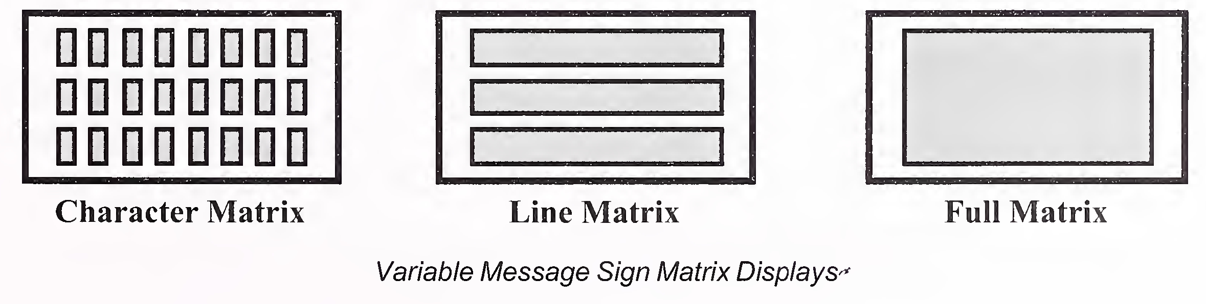
Messages are limited by the type of VMS used and its display space, configuration or matrix. There are three typical types of matrix displays: character, line, and full. In a character matrix a separate display space is made available for each letter of the text message and not recommended. A character matrix of 8 horizontal by 3 vertical has only 24 display spaces available. In a line matrix there is no physical separation between the characters in a single line of text. However, in a line matrix there still remains a separation between different lines of text. In a full matrix no physical separations exist between individual characters or lines in the message. A message can be shown at any size and location as long as it is within the display space. The exhibit below demonstrates the differences between the matrix types. Line and full matrix are recommended
 25
25
Messages displayed on a VMS are done by using single or multiple-phases. A phase is defined as the limits of the display area available for text, bitmaps, or animation. Messages that require more information than can be shown on a single VMS display space may require the use of multiple phases. Multiple phases allow more than one message to be displayed at a location.
The design process presented here demonstrates the steps needed for proper VMS deployment. It does not, however, take every possible variable into consideration. The designer must use proper judgment within each step for a successful deployment. Along urban streets VMS could be installed only on streets segments offering clear sight distance of at least 150 m in plain and rolling terrain. In hilly terrain, the distance for glance legibility shall be decided on the basis of design speed. Under no circumstances shall the front panel of such signs be used for any kind of advertising purpose.
expressways, the minimum distance between road signs and a VMS should be at least 250 m, and for NH 150 m.
Annex-A
(Clause 3)
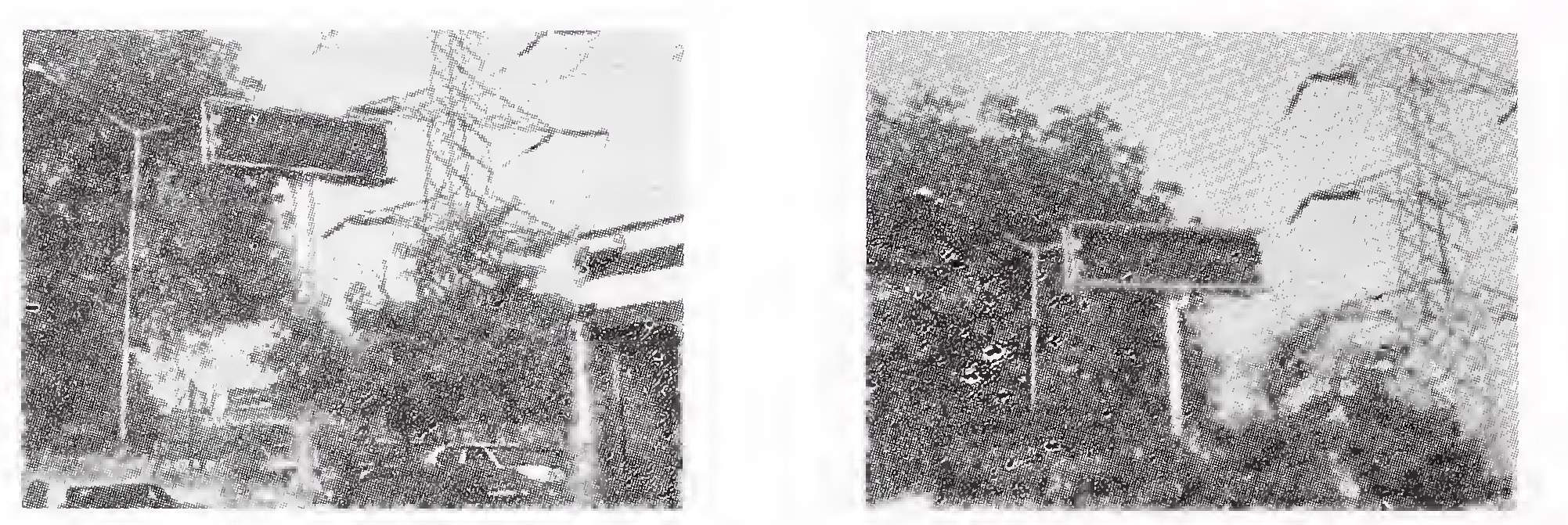
Photo 1 Varaible Message Sign Boards on NH-2
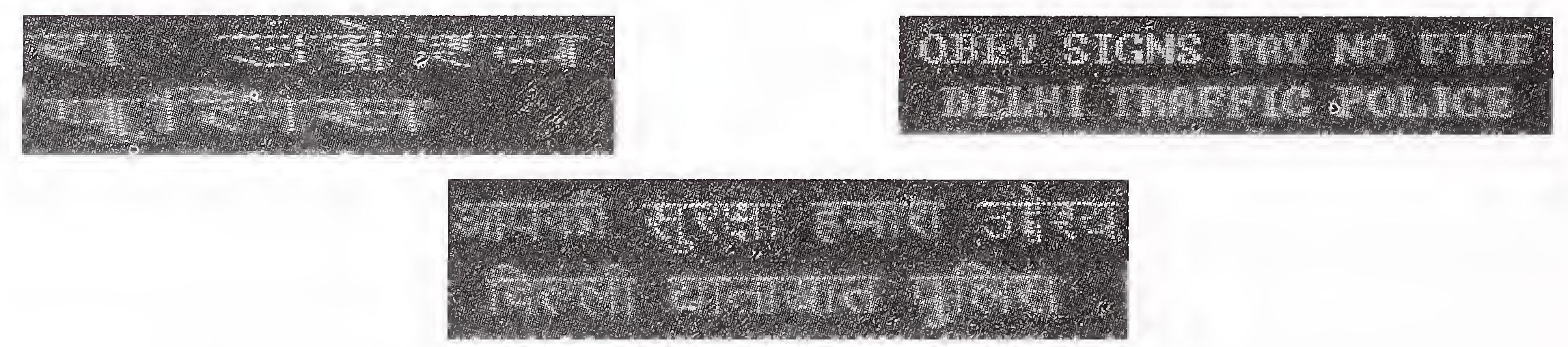
Photo 2 Typical Display of Traffic Messages through VMS Boards on NH-2
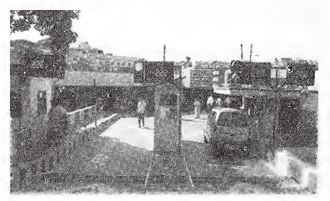
Photo 3 VMS for Parking Lots in Urban Areas
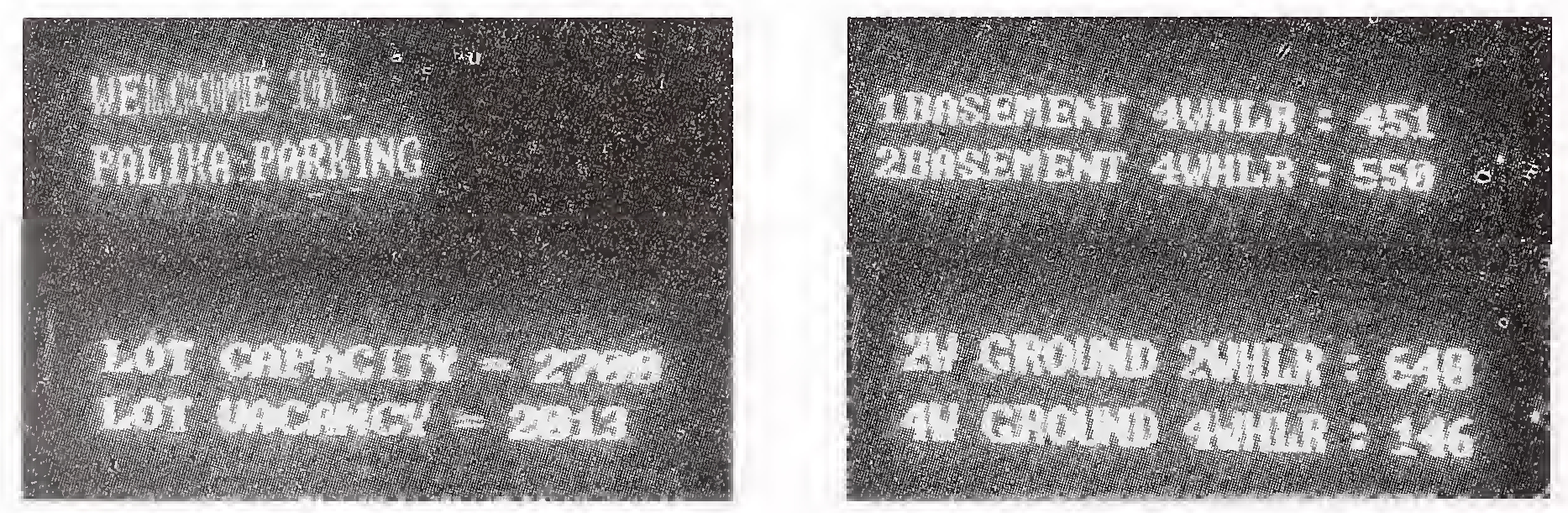
Photo 4 VMS Displays Showing Availability of Spaces for Parking28
Annex-B
(Clause 6.4)
TYPICAL VMS MESSAGES
| CLOSURE | |
| ACCIDENT AHEAD ROAD CLOSED | REST AREA CLOSED |
| CENTER LANE CLOSED AHEAD | RIGHT LANE CLOSED |
| EXIT CLOSED AHEAD | RIGHT LANE CLOSED AHEAD |
| FRONTAGE ROAD CLOSED | RIGHT SHOULDER CLOSED AHEAD |
| LEFT LANE CLOSED | ROAD CLOSED |
| LEFT LANE CLOSED AHEAD | ROAD CLOSED _____ KM AHEAD |
| LEFT SHOULDER CLOSED AHEAD | ROAD CLOSED AHEAD |
| RAMP CLOSED | ROAD TEMPORARILY CLOSED |
| RAMP CLOSED AHEAD | TUNNEL CLOSED AHEAD |
| CONSTRUCTION | |
| BRIDGE WORK AHEAD | PAVING OPERATIONS AHEAD |
| CONSTRUCTION AHEAD EXPECT DELAYS | ROAD PAVING AHEAD |
| CONSTRUCTION NEXT _____ KM | ROAD WORK AHEAD EXPECT DELAYS |
| CRACK FILLING AHEAD | ROAD WORK NEXT _____ KM |
| FRESH BITUMEN ON ROAD | ROAD WORKERS AHEAD |
| MEDIAN WORK AHEAD | SHOULDER WORK AHEAD |
| METAL PLATES AHEAD | SLOW MOVING VEHICLE |
| MOBILE PATCHING AHEAD | TRUCKS CROSSING |
| MOWERS AHEAD | WATCH FOR TRUCKS |
| NIGHT WORK AHEAD | WET PAINT |
| PAINT CREW AHEAD | WORKERS IN TUNNEL29 |
| DIRECTION | |
| ACCIDENT AHEAD ALL TRAFFIC MUST EXIT | KEEP LEFT KEEP RIGHT |
| ACCIDENT AHEAD BE PREPARED TO STOP | LANE CLOSURES AHEAD EXPECT DELAYS |
| ACCIDENT AHEAD EXPECT DELAYS | LANE CONTROL AHEAD |
| ACCIDENT AHEAD MERGE LEFT | LANE ENDS |
| ACCIDENT AHEAD MERGE RIGHT | LANE NARROWS AHEAD |
| ALL RAMPS OPEN | LANES MERGE AHEAD |
| ALL TRAFFIC EXIT | LEFT 2 LANES CLOSED |
| ALL TRAFFIC EXIT LEFT | LIMITED SIGHT DISTANCE |
| ALL TRAFFIC EXIT RIGHT | LOOSE GRAVEL AHEAD |
| ALL TRAFFIC MUST STOP | LOOSE GRAVEL ON ROAD |
| BUMP AHEAD | MAX SPEED _____ KMPH |
| CHECK FUEL BEFORE ENTERING | MERGE AHEAD |
| CONGESTED AREA AHEAD | MERGE LEFT |
| CURVE AHEAD | MERGE RIGHT |
| DETOUR | MERGE RIGHT |
| DO NOT PASS | MERGE RIGHT |
| EXIT HERE | MERGING TRAFFIC AHEAD |
| EXPECT DELAY | MINIMUM SPEED _____ KMPH |
| FORM ONE LANE LEFT | NO PASSING |
| FORM ONE LANE RIGHT | NO PASSING |
| FORM TWO LANES LEFT | NO SHOULDER |
| FORM TWO LANES RIGHT | NO WIDE LOADS |
| HEAVY TRAFFIC AHEAD | ONE LANE BRIDGE AHEAD |
| HEAVY TRAFFIC TO MOUNTAINS | ONE LANE TRAFFIC30 |
| PASS LEFT | SOFT SHOULDER AHEAD |
| PASS RIGHT | SPEED LIMIT STRICTLY ENFORCED |
| PAVEMENT ENDS | STAY IN LANE |
| PEDESTRIAN CROSSING | STEEP GRADE |
| PILOT CAR AHEAD | STOP AHEAD |
| PREPARE TO MERGE | TWO LANE TRAFFIC AHEAD |
| RIGHT LEFT 2 LANES CLOSED | TWO-WAY TRAFFIC |
| ROAD NARROWS AHEAD | UNEVEN PAVEMENT AHEAD |
| UNMARKED LANES AHEAD | |
| ROCKS ON ROAD | USE DETOUR |
| ROUGH ROAD AHEAD | USE DETOUR ROUTE |
| SHARP CURVE AHEAD | USE LEFT LANE |
| SHOULDER DROP OFF | USE RIGHT LANE |
| SHOULDER DROP OFF AHEAD | VEHICLES CROSSING |
| SIGNAL AHEAD | ROCKS ON ROAD |
| SIGNAL NOT WORKING | WATCH FOR STOPPED TRAFFIC |
| SINGLE LANE AHEAD | YIELD |
| SLOW TRAFFIC | YIELD AHEAD |
| FIRE | |
| EXTREME FIRE DANGER | |
| TRUCKS | |
| BRIDGE WEIGHT LIMIT AHEAD | RUNAWAY TRUCK RAMP OCCUPIED |
| LOW BRIDGE AHEAD | TRUCKS USE LEFT LANE |
| LOWER RUNAWAY TRUCK RAMP OCCUPIED | TRUCKS USE LOW GEAR |
| RUNAWAY TRUCK RAMP | TRUCKS USE RIGHT LANE |
| RUNAWAY TRUCK RAMP CLOSED | LANES SHIFT AHEAD31 |
| WEATHER | |
| ADVERSE CONDITIONS AHEAD | HIGH WIND ADVISORY |
| DENSE FOG AHEAD | HIGH WIND RESTRICTION |
| FLOODED ROAD AHEAD | HIGH WIND RESTRICTION HIGH PROFILE VEHICLES MAY BE STOPPED |
| FOG AND ICY CONDITIONS MAY EXIST | |
| FOGGY CONDITIONS MAY EXIST | POOR VISIBILITY AHEAD |
| GUSTY WINDS AHEAD | REDUCED VISIBILITY AHEAD |
| HEAVY FOG AHEAD | WATER ON ROAD32 |