This library of books, audio, video, and other materials from and about India is curated and maintained by Public Resource. The purpose of this library is to assist the students and the lifelong learners of India in their pursuit of an education so that they may better their status and their opportunities and to secure for themselves and for others justice, social, economic and political.
This item has been posted for non-commercial purposes and facilitates fair dealing usage of academic and research materials for private use including research, for criticism and review of the work or of other works and reproduction by teachers and students in the course of instruction. Many of these materials are either unavailable or inaccessible in libraries in India, especially in some of the poorer states and this collection seeks to fill a major gap that exists in access to knowledge.
For other collections we curate and more information, please visit the Bharat Ek Khoj page. Jai Gyan!
IRC:SP:74-2007
Published by
INDIAN ROADS CONGRESS
Kama Koti Marg,
Sector 6, R.K. Puram,
New Delhi-110022
2007
Price Rs.100/-
(Packing & Postage Extra)
PERSONNEL OF THE BRIDGES SPECIFICATIONS AND STANDARDS COMMITTEE
(AS ON 19.10.2006)
| 1. | Sharan, G. (Convenor) |
Addl. Director General, Ministry of Shipping, Road Transport and Highways, Transport Bhavan, New Delhi |
| 2. | Dohare, R.D. (Member-Secretary) |
Chief Engineer (R) (S&R), Ministry of Shipping, Road and Highways, Transport Bhavan, New Delhi |
| Members | ||
| 3. | Agrawal, K.N. | DG(W),CPWD (Retd.),C-33, Chandra Nagar, GHAZIABAD-201301 (UP) |
| 4. | Alimchandani, C.R | Chairman & Managing Director,STUP Consultants Ltd.,MUMBAI-400021 |
| 5. | Banerjee, A.K. | Member (T) NHAI (Retd.) B-210, Second floor, Chitranjan Park, NEW DELHI-110019 |
| 6. | Basa, Ashok | Director (Tech.) B. Engineers & Builders Ltd., BHUBANESWAR-751010 |
| 7. | Banerjee, T.B. | Chief Engineer, Ministry of Shipping,Road Transport and Highways,Transport Bhavan,NEW DELHI-110001 |
| 8. | Bandyopadhyay, T.K., Dr. | Joint Director General,Institute for Steel Dev. and Growth, (INSDAG) Ispat Niketan KOLKATA |
| 9. | Bongirwar, RL. | Advisor, L&T,B/1102, Patliputra Co-op. Housing Society Ltd. Four Bunglow Signal,MUMBAI-400053 |
| 10. | Chakraborty, S.S. | Managing Director,Consulting Engg. Services (I) Pvt. Ltd.,57, Nehru Place,NEW DELHI-110019 |
| 11. | Chakraborti, A. | Director General (Works)CPWD, Nirman Bhavan, Room No. 203, A Wing NEW DELHI-110011 |
| 12. | Chakrabarti,S.P. | CE, MOST (Retd.) Consultant, Span Consultants (P) Ltd. 92C, Gurudwara Road, Madangir, NEW DELHI-110062 |
| 13. | Dhodapkar,A.N. | Chief Engineer,Ministry of Shipping, Road Transport and Highways, Transport Bhavan, NEW DELHI-110001 |
| 14. | Gupta, R.K. | Executive Director(B&S)Bidges & Structures Dirett., Room No. 213, Annexe II,Research Design & Standards Orgn., Manak Nagar, LUCKNOW-226001 |
| 15. | Ghoshal,A. | Director and Vice-President, STUP Consultants Ltd. P-11, Darga Road, Park Circus, KOLKATA-700017 |
| 16. | Indoria, R.R | Chief General Manager, NHAI, Plot No. G-5 and 6, Sector 10, Dwaraka, NEW DELHI-110075 |
| 17. | Joglekar,S.G. | Director (Engg.Core), STUP CONSULTANTS Ltd. Plot No. 22A, Sector 19C, Palm Beach Road, Vashi,' NAVI MUMBAI-400705 |
| 18. | Kand,C.V. | CE, MP PWD (Retd.) Consultant, E-2/136, Mahavir Nagar, BHOPAL-462016 |
| 19. | Kanhere,D.K. | Chief Engineer (NH), Block No. A-8, Building No. 12, Haji Ali Govt. Officers Qtrs. Mahalaxmi, MUMBAI-400034 |
| 20. | Koshi, Ninan | DG(RD) & Addl.Secy., MOST (Retd.), H-54, Residency Greens Green Woods City, Sector 46, GURGAON-122001 (Haryana) |
| 21. | Kumar, Prafulla | DG(RD) & AS, MORT&H (Retd.)D-86, Sector 56, NOIDA-201301(i) |
| 22. | Kumar, Vijay | E-in-Chief (Retd.) UP, PWD E-002, Krishna Apra Residency, Sector 61, NOIDA-201307 (UP) |
| 23. | Kumar, Ram, Dr. | Scientist, F Central Road Research Instt.Delhi Mathura Road, NEW DELHI-110020 |
| 24. | Manjure ,P.Y. | Director, Freyssinet Prestressed, Concrete Co. Ltd., MUMBAI-400018 |
| 25. | Mukerjee, M.K. | CE, MOST (Retd.) 40/182, Chitaranjan Park, NEW DELHI |
| 26. | Narain, A.D. | Director General (Road Dev.) & Addl. Secretary, MOST (Retd.),B-186,Sector 26, NOIDA-201301 |
| 27. | Ninan,R.S. | Chief Engineer, Ministry of Shipping, Road Transport & Highways, Transport Bhavan, NEW DELHI-110001 |
| 28. | Puri, S.K. | Chief General Manager,National Highways Authority of India, Plot No. G-5 & 6, Sector 10, Dwarka, NEW DELHI |
| 29. | Rajagopalan, N. Dr. | Chief Technical Advisor L&T-RAMBOLL Consulting Engineers Ltd., 339-340, Anna Salai, Nandanam CHENNAI |
| 30. | Sharma,R.S. | Past Secretary General,IRC, C-478 Second Floor, Vikas Puri, New Delhi-10018 |
| 31. | Sinha N.K. | DG(RD) & SS, MORT&H (Retd.) G-1365, Ground Floor, Chitranjan Park, NEW DELHI-110019 |
| 32. | Sinha,S. | Addl. Chief Transportation Officer, CIDCO Ltd. CIDCO Bhavan, 3rd floor, CBD Belapur,NAVI MUMBAI-400614 |
| 33. | Tandon Mahesh,Prof. | Managing Director Tandon Consultants (P) Ltd., ,NEW DELHI |
| 34. | Tamhankar M.G.,Dr. | Emeritus Scientist BH-1/44, Kendriya Vihar Kharghar, Sector 11, NAVI MUMBAI-410210 |
| 35. | Velayutham V. | DG (RD) & SS (Retd.) MOSRTH, Flat No. 4, Nalanda Appartment, D Block, Vikaspuri, New Delhi-110018. |
| 36. | Vijay, P.B. | DG(W), CPWD (Retd.) A-39/B, DDA Flats, Munirka, NEW DELHI-110062 |
| 37. | Director & Head (Civil Engg.) |
Bureau of Indian Standards,Manak Bhavan, NEW DELHI |
| 38. | Addl.Director General (T.P. Velayudhan) |
Directorate General Border Roads, Seema Sadak Bhawan, Nariana, New Delhi |
| Ex-officio Members | ||
| 1. | President, IRC | (Tribhuwan Ram), Engineer-in-Chief, UP, PWD, Lucknow |
| 2. | Director General (Road Development) | Ministry of Shipping, Road Transport and Highways, Transport Bhavan, New Delhi |
| 3. | Secretary General | (V.K. Sinha,) Indian Roads Congress, Kama Koti Marg, Sector 6, R.K. Puram, New Delhi. |
| Corresponding Members | ||
| 1. | Bhasin, P.C. | ADG (B), MOST (Retd.) 324,Mandakini Enclave New Delhi |
| 2. | Reddi, S.A. | 72, Zenia Abad, Little Gibbs Road, Malabar Hill, MUMBAI-400006 |
| 3. | Raina V.K.,Dr. | Flat No.26, Building No. 1110 Road No. 3223, Mahooz Manama-332 BAHRAIN (Middle East) |
| 4. | Rao,T.N. Subba, Dr. | Chairman, Construma Consultancy (P) Ltd. MUMBAI-400052(ii) |
GUIDELINES FOR REPAIR AND REHABILITATION OF STEEL BRIDGES
The Steel and Composite Structures Committee (B-5) of the Indian Roads Congress was reconstituted in 2006 with the following personnel:
| Ghoshal,A. | Convenor |
| T.K. Bandyopadhyay, Dr. | Co-Convenor |
| Ghosh, U.K. | Member-Secretary |
| Members | |
| B.P. Bagish, Dr. | |
| Banerjee,T.B. | |
| Bhattacharya, A.K. | |
| Baul, Saibal | |
| Chaudhary, Sudip | |
| Kalyanaraman, V., Dr. | |
| Mathur, I.R. | |
| Mazumdar, S. | |
| Ghosh, Achyut, Prof. | |
| Goel, R.K. | |
| Rao, Harshavarhan Subba, Dr. | |
| Roy,B.C. | |
| Sharma,D.D. | |
| Singh, Virendera | |
| Sreenivasa, K.N. | |
| Srivastava,A.K. | |
| Tandon, Mahesh, Prof. | |
| Yadav, V.K.,Dr. | |
| Vijay, P.B. | |
| Rep. Of Garden Reach Shipbuliders | |
| Engineers Ltd. (Kolkata) | |
| Ex-officio Members | |
| President, IRC | |
| DG(RD) MOSRT&H | |
| Secretary General, IRC | |
At its first meeting held on 30th April, 2003, the former Steel Bridges Committee (B-7) felt that in the light of renewed interest in Steel and Composite Highway Bridges and Flyovers, there is a need to bring out separate documents for different types of superstruture and also for strengthening/rehabilitation of old Steel Bridges which are still in service. Since the IRC document “Guidelines on Techniques for Strengthening and Rehabilitation of Bridges” (IRC:SP:40) does not comprehensively cover steel bridges, the Committee felt that there is a need to bring out a sperate document entitled “Guidelines for Repair and Rehabilitation of Steel Bridges”. While highlighting the special requirements for design and fabrication, it was decided that the Guidelines would generally be in line with relevant IRC Codes and Special Publications. Additional inputs from pertinent AASHTO Guide Specifications and Manuals, NCHRP Reports, RDSO Guidelines and text book were also considered in the preparation of the Guidelines.
The draft of the Guidelines was prepared by a Sub-committee comprising of the following members:
| S/Sh. A. Ghoshal | Convenor |
| U.K. Ghosh | Member |
| Dr. T.K. Bandhyopadhyay | Member |
| K.N. Sreenivasa | Member |
| Dr. B.P. Bagish | Member |
| R.K. Goel | Member |
The former B-7 Committee under the Convenorship of Shri P.B. Vijay in its meeting held on 12th December, 2005 had finalized the draft Guidelines inviting comments, if any. The draft was referred to the newly constituted Bridges Repair and Rehabilitation Committee (B-8) by the IRC for its comments, keeping in view IRC:SP:40. It was vetted by the B-8 Committee, with minor modifications in its meeting held on 11th March 2006. The newly constituted Steel and Composite Structures Committee (B-5) in its meeting held on 9th May, 2006 endorsed the modified draft and recommended for its placement before the Council through BS&S Committee.1
The draft document was approved by the Bridges Specifications and Standards Committee in its meeting held on 19th October, 2006 and the Executive Committee authorized Secretary General, IRC to place the same before Council, The document was approved by the IRC Council in its 179th meeting held on 18th November, 2006 in Panchkula subject to incorporation of some suggestions.
The B-5 Committee considered the views of the Council in its meeting held on 9th March, 2007 and felt that the suggestions were already in place in the document and recommended that the document could be published.
The topics covered in the present document aim at restoring the bridges to their originally intended service level or to retrofit them upto capacity presently required.
Inadequacies could be due to various reasons:
Assessment of residual fatigue life and rating of existing steel bridges form part of maintenance activities and are not covered in the present publication. It also does not cover replacement of an entire bridge, nor a new construction.
For rating and posting of bridges reference is made to IRC: SP:37.
Deterioration in steel bridges can be classified according to two broad causative factors, viz, natural deterioration and deterioration due to man-made situations. Examples of the former are those caused by atmospheric corrosion, earthquake, floods, fire etc. Deterioration caused by pollution, stress corrosion, fatigue, deficiencies in material characteristics, foundation settlement, accident, war, terrorist attack etc. come under man-made situations.
In most of these situations, the effect of distress depends on the type of the bridge, details adopted, quality of the structure, type of environment and above all, the level of routine maintenance work.
Atmospheric corrosion in steel is essentially an electrochemical process of flow of electricity and consequent chemical changes. Two important points are to be noted in this connection:
The immediate or direct effect of atmospheric corrosion is loss of area of either the steel member itself or the fasteners, causing increase in stress in the member or the fasteners. Indirectly, this makes the member as well as the fasteners vulnerable to stress corrosion and fatigue failure.2
Locations subjected to high tensile stress are prone to higher rate of corrosion. This phenomenon is commonly referred to as ‘stress corrosion’ As the cross sectional area of an already highly stressed member is reduced due to corrosion, the resultant increase in stress may initiate crack. This type of distress is found mostly in specific areas where high concentration of stress is developed, such as eye bars of pins in suspension and cable stayed bridges.
Brittle fracture is characterised by a low stress fracture of the material, which usually occurs suddenly with little or no plastic deformation and other warning signs.
There are three key factors which lead to brittle fracture. These are :
Lamellar tearing is the separation of parent metal caused by Through thickness' strains induced by weld metal shrinkage. When the resultant stress is carried in the 'through thickness' direction, any lack of cohesive strength of the steel material in this direction causes the plate to be separated. Shape of non-metallic matter in the steel (manufacturing defects) as well as factors related to welding process (e.g. Preheat, weld restraint in the through thickness direction etc.) are contributory factors for lamellar tearing of steel.
In bridges, steel elements are subjected to moving loads, which cause fluctuations of stresses in steel elements. This fluctuation of stresses reduces the ultimate strength of steel member considerably as compared to gradually applied static load. Thus, a member may be able to withstand a single application of the design load, but may fail if the same load is repeated for a large number of times. This phenomenon of progressive localised permanent structural change due to fluctuating stresses, which may initiate cracks in the member, is termed 'fatigue'. This reduction in strength depends on two factors, viz., number of local repetitions (cycles) and range of stress due to these load repetitions. Fatigue cracks occur at the tension zone of the members. This tension zone varies from member to member or within the same member, depending upon application of moving loads. Also, this phenomenon is applicable to connections/ joints which are subjected to load repetitions.
In welded joints, the fatigue strength of steel tends to be reduced due to pronounced changes in the structure (hard grain formation) in and around Heat Affected Zone (HAZ) and properties (lowering of ductility) of the steel due to improper or no treatment of HAZ. As a result, welded bridges are more prone to fatigue cracks than riveted/High3
Strength Friction Grip (HSFG) bolted ones. Also, the crack developed at the weld tends to progress and may affect both the connecting components and surrounding members/ elements/or connectors (due to increase in stresses) and consequently, the entire structure may be damaged.
In road bridges, the range of stresses is not high, because of lighter moving loads compared to dead loads and less vibration as compared to railway bridges. Thus fatigue related distresses directly due to range of stresses are not very common in road bridges. However, stress raisers in tension zone, such as sharp notches or comers, abrupt change in cross sections, can cause stress concentration. Also atmospheric corrosion in many cases, reduces cross sections of members, resulting in increase in stress levels, which for a particular loading cycle may initiate cracking leading to fracture.
Physical damages (buckling) of different bridge components due to accidents are quite common. Steel bridges spanning across roadways underneath and having inadequate headroom are very often damaged due to vehicular collision from underneath contact. In cases of through and semi-through type steel bridges, vehicles using the bridge may damage individual members while passing. Also there are many examples of vessels using waterways and colliding with bridge structures from underneath.
Bridge may be damaged by natural calamities such as floods, landslides, earthquakes or by explosions from war action, sabotage etc.
For steel bridges supported by nonductile substructure elements, at these locations supertructure has the likelihood of getting damaged mostly in the form of buckling and/or connection fracture of diaphragm braces.
Steel sections can suffer slow erosion due to weathering action, viz., sand storm, wave action etc.
In industrial areas, chemical corrosion may occur due to presence of chemicals (chlorides, oxides of sulphur etc.) in the atmosphere.
All the above situations need to be appropriately examined for requisite redressal.
A bridge structure may suffer inadequacy due to under design or faulty construction, needing strengthening.
It is quite common that heavier loading standards and changed codal requirements based on improved knowledge are introduced from time to time, which may render the bridge structure inadequate, needing strengthening.
It is sometimes necessary to introduce increased vehicle clearance requirements to meet new traffic demands, such as introduction of new types of vehicles, container services etc. This situation mostly affects through type bridges, necessitating modifications in structural arrangements.
The broad activities in this process are
stress capacity and residual life
These activities are briefly discussed in the following paragraphs.
This activity involves study of available records and drawings pertaining to the concerned bridge. If adequate records and drawings are not readily available, interviewing old employees of the organisation or persons residing in the vicinity of the site of the bridge may provide some valuable information. The data of construction and history of subsequent repair work or replacement of major members should be ascertained at this stage.
The date of construction provides the vital information about the age of the bridge. Knowledge of age has important bearings. Some of these are:
Review of the environment covers the effect of the environment on the existing bridge, as also the effect of the rehabilitation work on the environment.
Regarding the former, the following situations are relevant:
The rehabilitation scheme should consider these environmental hazards and recommend appropriate protective measures.
As regards the effect of rehabilitation work on the existing environment, dumping of debris, release of chemicals, spills of waste materials should be avoided. These aspects should be considered at the planning stage and proper specification should be incorporated in the bridge rehabilitation document itself.
For effective rehabilitation of a bridge, the first step is to locate the damages/ defects/ deficiencies incurred by its various components. For this purpose a Special Inspection is carried out. This inspection comprises of the following main activities:5
Ideally the structural designer who is entrusted to develop the rehabilitation scheme should participate as a member of the inspection team. This would enable him to understand the condition of the structure, location and extent of the damaged area much better than going through the report pages prepared by someone else, and thus formulate a better rehabilitation strategy. It is important to note that certain components of a bridge are highly inaccessible. Therefore, reliable and efficient working hands are to be included in the inspection team to carry out the inspection of such inaccessible areas. When it is not possible for the designer to inspect the bridge, the inspection report assumes much higher importance, as the designer has to fully depend on this report for developing his strategy for rehabilitation.
The bridge inspector should, therefore, be conversant with the behaviour of the structure under actual loading conditions. He should be conversant with the design and construction features of the structure. Deterioration of material due to corrosion, weathering, fatigue etc., should be easily apparent to him. He should be able to identify the areas which are prone to deterioration. He should be able to properly interpret what is observed and report the same correctly in clear language and by simple sketches, if necessary.
It is often preferable to form an inspection team comprising of engineers and technicians, with experience and knowledge of diverse areas such as structural design, construction, maintenance, emergency repair etc. Assistance of specialist agencies may also be sought to help the inspection team for special structures such as movable bridges, suspension bridges, cable stayed bridges etc.
While all the components of a bridge need inspection, there are certain areas, connections and splices which are susceptible to serious defects, and therefore need particular attention during inspection. Some of these are:
Some of the most useful inspection tools are : a 2m pocket tape, a 30m steel tape, chipping hammer, paint scraper, wire brush, plumb bob, vernier or jaw type callipers, small level, steel straight edge, feeler gauges, spanners, wrenches, rivet testing hammer, calibrated torque measuring wrench for HSFG bolts, magnifying glass of (10X or higher magnification), binocular, flash light, sensitive thermometer, mirror, piano wire and camera. Precision type levelling instrument and theodolite for checking camber/ deflection sway etc. may also be arranged if necessary.
For inspection of structural elements situated above deck level, simple equipment such as ladders, portable platforms, planks etc. may be used for inspection. However, in bridges where underside structures are not easily accessible, temporary scaffolding system, special equipment such as bucket snoopers, custom made travelling gantries etc. are required to be used. Where access from roadway below is available, truck mounted hydraulically operated telescopic hoists fitted with bucket or platform may be usefully employed.
As a first step the bridge structure should be visually inspected. Most cracks are first detected during the visual inspection. Visual inspection is carried out by naked eye, or by using binoculars from a convenient location.
Usual and most reliable sign for detection of cracks during visual inspection is the oxide or rust stains that develop at the crack after the paint film has cracked. At this level of inspection only larger cracks will be detected.
In the next step, close visual inspection of critical locations and suspect details (that show no visual evidence of cracking through paint film) should be done using magnifying glass of 10X or higher magnification. Cracks detected during earlier inspections should also be inspected in detail for their extension. It may be necessary to remove the paint film for the inspection; however, this should be done carefully so that any fine crack remains intact for detection.
For further detailed inspection, nondestructive testing (NDT) methods are generally employed. Some of the common methods are briefly described below:
The remaining thickness of a corroded member can be measured with the help of callipers, where access is available on both sides of the member. Where such access is not available, ultrasonic thickness gauge can be used. The equipment is very handy and can measure the thickness from any one surface to an accuracy of 0.1mm. The gauge usually gives a digital reading.
Cracks in steel can be detected by using several non-destructive tests. Some of these are described below:
Dye penetration test :
This test is a simple and low cost nondestructive testing for detecting minute surface cracks.
First the surface area is to be cleaned to remove any dirt, rust or paint, to enable dye penetrant to enter into the crack. The dye penetrant is then applied over the surface by spraying or brushing. The dye seeps into any7
cracks or other defects open to the surface. After allowing a penetration time of about 20 minutes, the excess penetrant is cleaned by using a solvent. A developer (like a chalk powder) of contrasting colour with high absorbent quality is then applied by dusting. In case of any surface defect, the dye penetrant is drawn out from the crack by blotting action of the developer and appears as stain on the chalk surface. Sufficient time is to be allowed for the dye penetrant to blot on the developer. The surface is then examined by using a magnifying glass. The surface is to be finally cleaned after the test (Ref: IS:3658:1981).
Ultrasonic Test :
This method is suitable for detecting surface or sub-surface defects in steel. A high frequency sound beam is introduced into the area to be tested by means of an ultrasonic transducer. The sound beam travels through the steel, and as soon as the crack is met, it reflects back to the transducer. This produces a voltage impulse, which appears in the cathode ray tube (CRT). In this test access from only one side of the material is required. Since portable testing machines are available, this test can be conveniently carried out at a bridge site. However, this test requires specialised skill in interpreting the pulse-echo pattern appearing on the screen (Ref: IS-3664:1981 and IS-4260:1986).
Radiographic examination :
In this method both surface and subsurface defects can be detected. X-rays or Gamma rays are passed through the member to be tested, which create an image on a photosensitive film. The defects are shown on the film as dark lines of shaded areas. In this method, permanent record of every test is available. Permanent record can be made available through radiographic examination as compared to ultrasonic testing method. The former can be considered more reliable. However, for radiographic examination access from both sides of the test area is required - with radiation source placed on one side and the film placed on the other side. It requires specialised skill in performing this test (Ref: IS-1182:1983). Also, strict safety regulations are required to be observed during this examination. For protection against radioactivity refer IS:2598-1966.
Holography
Holography is a variant laser technique used to obtain 3D images and is used as a tool for non-destructive testing of materials. The detection of defects can be observed at the micro level. This is an effective tool for testing in highly localised zone and is quite effective in detection of the location of flaw.
Magnetic Particle Test:
This test is suitable for detection of surface or sub-surface cracks. In this method magnetic field is first set up in the member to be inspected by means of an electric power source or permanent magnet. Fine dry iron particles are then dusted on the test area. Alternatively, liquid detection medium carrying magnetic iron powder can also be used. Crack causes discontinuities in magnetic field which results in a pattern of collection of iron particles along the crack and the outline of the crack becomes clearly visible. A highly trained inspector is required to perform this test successfully. The method is only effective in a limited range of situations and is normally not popular for use in field conditions (Ref: IS:3703:1980 and IS:5334:1981).
Sometimes, it is considered necessary to carry out tests to establish the physical and chemical properties of certain members of a bridge. For example in cases of requirement of welding repairs, the selection of electrode would depend upon the chemical composition of the steel. For this purpose a8
specimen (coupon) is taken from the steel structure itself. However, these specimens should not be taken indiscriminately from the main members. These members should first be checked by the designer vis-a-vis strength and stability. In case a coupon is obtained from a main member, appropriate bolted repair fulfilling the equivalent sectional requirement at a particular section detail should be designed and introduced.
Sometimes, the static behaviour of a bridge is examined experimentally by applying actual or simulated design loadings and observing the effects on the critical members by instrumentation. Prior to loading the structure, strain gauges are fixed at critical locations. The structure is then loaded by placing trucks and/or train of wheel loads of known weights satisfying the requirements of relevant IRC code at various points of the bridge and the strain is recorded. Based on the strains at different locations the actual stresses in the members are calculated and compared with the theoretical allowable design stresses.
Testing may also be carried out by passing test vehicles over a bridge at incremental speeds to ascertain the overall behaviour of the structure under normal traffic load. Vibrations, opening of cracks in damaged members, behaviour of bearings are some of the features that may be observed during such tests. Measurements can be taken by various types of instruments including electronic and laser techniques etc.
During inspection, top priority must be given to safety. It is necessary to draw out a comprehensive safety programme well in advance of the proposed inspection activity. This programme should cover the safety and welfare of the persons at work as well as members of the public against risks to accident, health and safety arising out of the activities at work. The programme should include standard bridge inspection safety procedures of the concerned bridge authorities, as well as additional safety requirements such as traffic control procedures to conform to local regulations. Safety vests, helmets, work boots should be used by every member of the inspection team. Where climbing is required, suitable safety belts should be used. Special precautions should be taken for night time work. A first aid box should accompany the inspection team.
Clear and sharp photographs are very useful documents to support bridge inspection report. Thus modem cameras fitted with wide angle and telescopic lenses are very useful during inspection. It is advisable to include in the photograph a clearly marked scale or an easily recognisable item for easy comprehension of the scale of the detail.
Based on the results of the inspection, calculation of stress levels for all critical members of the bridge structure should be carried out in respect of both dead and live loads. The dead loads should include the estimated load for additional materials for repair and strengthening. Calculation of stress levels would enable the designer to assess the residual capacities of individual members and joints that are available for live loads and other incidental loads and compare these with the actual load effects on these members and joints. This would help to identify the members and joints which are deficient and need strengthening.
To assess the capacity of joints by calculations is more difficult since the inspectable parts of the joint are restricted and also the design of joints mostly give rise to stress concentrations and plastic (unknown)9
redistribution of load between the various connectors (i.e. rivets, bolts, welds). However, obvious deficiencies can be studied for their effect on the capacity of the joint and some measures to overcome defects can be considered, if it can be reliably executed.
This activity is carried out broadly in two stages, viz., concept stage and design stage.
During this stage the various options for solution are considered in detail. A few relevant points need to be considered in this context:
Having identified a few viable schemes these are subjected to rigorous analysis and design work in order to finalise the strategy for rehabilitation. A few relevant aspects are discussed hereunder:
(i) Dead load stresses
Members of an erected bridge are already subjected to dead load effects. Therefore prior to undertaking rehabilitation work, the structure should be relieved of the dead load. If this is not done, the existing members will continue to carry the dead load and will already be stressed to the extent of dead load effect. Consequently, the capacity of the new material will remain underutilised, as this cannot reach the permissible stress level without overstressing the existing members. In case it is not practicable to relieve the dead load, the new material should be considered to carry the live loads only.
There are a few methods for relieving the dead load stresses of an existing bridge. The most common method is to jack up the girder at a few locations and provide temporary support underneath.
Provision of temporary or permanent external prestress is also a very efficient method of relieving effect of D.L.. For cases with large heights and also over perennial rivers the external prestressing for rehabilitation of bridges has definite advantages.
(ii) Redundancy and fracture critical member
A redundant structure has, within itself, a multiple load carrying mechanism, so that, if one mechanism fails or weakens, the load will be carried by another mechanism. A non-redundant structure, on the other hand, does not have multiple load carrying mechanism and consequently failure of a single element (fracture critical member) may cause collapse of the structure.
The failure of any joint will have10
similar effect. The joints are more difficult for inspections and repair. Hence, providing alternative paths for load transfer is an important consideration in evolving rehabilitation strategy.
(iii) Fatigue effect
Fatigue effect should be considered while developing the rehabilitation details. Some of the details which need particular attention include stress raisers in tension zone such as notches, sharp comers, sudden changes in cross sections which cause stress concentration etc.
While developing welded details for rehabilitation, the following recommendations would help in reducing fatigue related cracks:
(iv) Connections
New fasteners should be compatible with the existing fastening system . As far as possible welding should be avoided on existing riveted/bolted connections. If used, welding should be designed to transfer entire load. However, before selecting welding as an option, weldability of the parent material must be ascertained first.
Defective rivets are best replaced by turned and fitted bolts, as the load transfer behaviour of these bolts are nearly identical to that of rivets. If, However, High Strength Friction Grip (HSFG) bolts are used the efficacy of the existing rivets should be checked.
(v) Eccentricity
While adding new materials for strengthening an existing damaged member, care should be taken to ensure that the centre of gravity of the strengthened section coincides, as far as possible, with the centre of gravity of the original section, in order to avoid secondary stresses due to eccentricity. In case it is not possible to achieve this requirement, the effect of eccentricity should be considered in the design.
Drawings and specifications for rehabilitation scheme prepared by the engineer should be clear and unambiguous. All details as also sequence of proposed operation at site should be clearly indicated in the drawings and specifications. The working drawings prepared by the contractor should be based on the engineer's conceptual design drawings, but must follow the actual measurements at site. The drawings should clearly indicate the scope of work for inclusion of new element and/or deletion o: existing elements satisfying the design requirements. Also, drawings should cleary specify and demarcate the existing and new elements of the strcture.
Fabrication and erection of every pan of the work should be done most accurately, so that the parts fit properly together on erection. Flame cutting and/ or dismantling of existing members should be done carefully so as not to damage the adjacent steel work. While dismantling existing members, adequate temporary supports should be provided to ensure stability of the entire structure. Care should be taken to eliminate any differential settlement between temporary supports.
Implementation of a rehabilitation scheme for an existing bridge is mostly a time bound project. Therefore, prior detailed planning and proper monitoring during implementation are imperative for successful11
completion of such a project.
In a rehabilitation work, certain problems not envisaged earlier, may arise at site and the supervisory team at site is often called upon to solve such problems on the spot. The team at site should therefore be well equipped to meet such contingencies.
This section briefly dealswith
suggested remedial solutions for inadequacies that commonly occur in existing steel bridges. The items covered are:
Corrosion is the most common cause of damage in existing steel bridges. The solution for rehabilitation of a corrosion-damaged member depends primarily on the degree of corrosion and its extent over the surface area. Some typical solutions for damage due to corrosion are described below:
(Some of these measures are illustrated in Fig. 1 to 4 of the Annexure.)
Cracks occurring in isolated locations can be repaired by drilling a hole of 13.5 to 23.5mm diameter at about 20mm beyond the12
tip of the crack, along its assumed line of further progress, to arrest the crack propagation. This will generally be a temporary repair and should be followed by fixing splice plates or splice angles with adequate number of bolts on either side of the crack. This is a very common solution for isolated cases of cracks. For multiple cracks in a single member it may be desirable to replace the cracked member by an identical member. Alternatively only the portion of the member, which has been damaged, may be replaced and an adequate splice connection between the new part and the existing part may be provided.
In welded girders, typical cracks may occur in the web near the lower end of the welded stiffener connection to the web. These cracks can be repaired by drilling holes beyond the tips of the crack and then gouging out the cracked portion and depositing weld metal in its place, followed by removing the excess metal by grinding. However, for undertaking field welding, the chemical composition of steel should be ascertained and appropriate electrode should be chosen in consultation with experts. A suitable, bolted splice on the other face of the web would provide added strength.
(Some of these measure are illustrated in Fig. 5 to 7 of the Annexure)
Local Buckling and bending of members due to vehicle collision or accident may be rectified either by mechanical means or by application of heat. However, the latter method is not popular amongst technicians.
For mechanical straightening, the recommended process is to slowly apply heat in the damaged area and then straighten it by mechanical means avoiding impact load. The member should then be allowed to cool without application of any external aid. Straightening of the member without application of heat (i.e. in ambient temperature) is generally not recommended, as the heavy external loads required for this process might adversely affect the properties of steel.
Increased Loading
In general, the procedures available for upgrading the structure for increased loading are:
Components
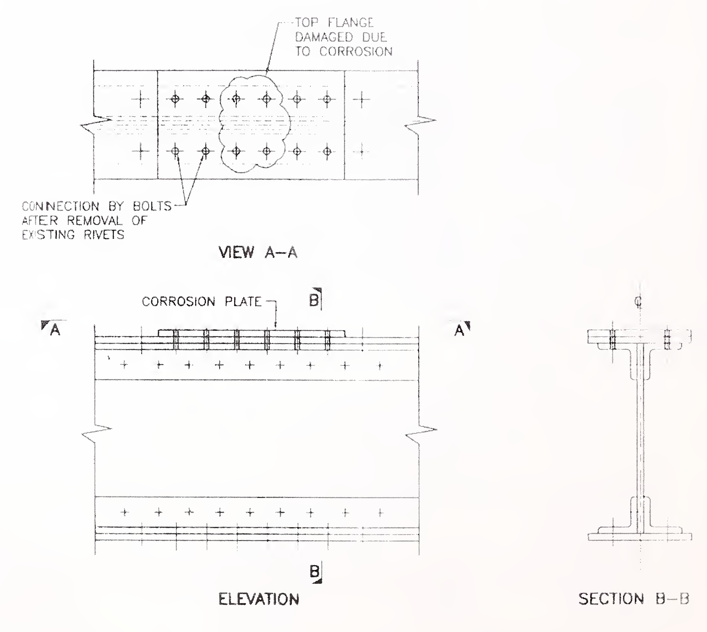
Capacities of rolled beams and plate girders can be increased by adding cover plates to the top and bottom flanges near the midspan. Lengths of the cover plates and their cut-off points are to be determined by design check. In case of rolled beams and welded plate girders the cover plates can be welded. However, in order to avoid fatigue related cracks, it is preferable to extend the cover plates to the ends, instead of terminating these at the theoretical cut-off point. For riverted plate girders, cover plates are to be fixed by bolts in a similar manner described in clause 5.1.1. above
For truss bridges, capacities of deficient main members such as top and bottom chords, diagonals and verticals can be enhanced by providing additional steel areas to these members by bolting plates to the webs or flanges of the members.
Capacity of top chords and other compression members of a truss bridge can be increased by reducing the effective lengths of these members. This can be achieved by subdividing the panels by introducing new members.
Live load capacity of a bridge can be13
increased if the dead load of the structure is reduced. One common example of this solution is replacement of the existing RC deck slab by orthotropic steel deck system.
Capacity of an existing bridge can be increased by incorporating changes in the details, so as to modify its structural system. For example, simply supported spans of longitudinal stringer beams in the deck system can be converted to continuous beams by suitably modifying the end connection details, thereby improving their load carrying capacity. Another method of augmenting the capacity of an existing bridge is by providing additional supports from below the underside of the girder at one or more points. Similarly, shifting of support points from the ends of the bridge to the next inward panel point may increase the capacity of the girder. The new configuration would be a reduced span with cantilevered panels at the ends. Another innovative method for increasing the load carrying capacity of an existing bridge is by introducing counterbalancing forces in the structural system by means of external posttensioning tendons, which work much the same way as in a post-tensioned concrete beam. This procedure induces new stresses in the structure and reduces the effects of the existing dead or live loads on the structure. Thus the live load capacity of the bridge is increased.
Existing through type bridges may need modifications to accommodate such requirements. End portal systems and sway bracings are the most common members that are affected. These components would be required to be relocated to clear the new dimensions. In case space is not available within the structure, it may be necessary to place the portal bracings and sway bracings above the bridge structure and fix these on to stools placed over the top chords at node points to clear the new clearance diagram. It is necessary to carry out design checks to ensure that the adopted system is adequate to transmit the lateral forces from the top chords to the bearings.
Some sketches showing a few typical connections covering modifications/rehabilitation work elaborated above are given in the Annexure.
COMMON PROBLEMS AND REMEDIAL SOLUTIONS
Bearings are primarily required to transmit loads to the foundations and to allow movements of the supporting superstructure. Although relatively small components in bridge structures, these are of significant importance for the proper functioning of any bridge. In many occasions distress in the superstructure as well as in substructures have been found to be due to improper functioning of the bearings. In this section, some of the common problems associated with bearings and their remedial solutions have been discussed.
As discussed earlier, corrosion and rusting in steel are mostly caused by water, dust and debris, which often collect at the location of bearings, have the tendency to absorb and retain moisture and thereby cause corrosion. Therefore, it is imperative to ensure that debris are not allowed to accumulate at the location of bearings.
Heavy corrosion on the contact surfaces increases the coefficient of friction significantly, thereby impeding the movement of sliding plates or rollers, and rendering the bearings ineffective. Often smaller components such as tooth bars or pins get corroded, resulting in restriction in the movement of the bearing.14
When bearings show effects of severe corrosion, these may need temporary removal and thorough check up. These should be rehabilitated by replacing damaged components, if necessary, and then re-erected after painting and greasing. Where components do not show any major loss of section due to corrosion, they may need only cleaning in situ and greasing.
Misalignment of bridge bearings may restrict the movements of the superstructure and induce additional forces in the bridge structure. Misalignment is caused by excessive vibration of the superstructure due to moving loads, severe earthquake, error in setting the bearings defective fabrication, or non linear and non-ductile substructure movement due to severe earthquakes or settlement of foundation due to overload.
A misaligned bearing can be rehabilitated by first jacking up the bridge superstructure to relieve the load on the bearing, introducing temporary props to support the structure, and then re-setting the bearing components with correct alignment, giving due consideration to the temperature effect for the inclination of the rollers. Normally jacking points are pre-located in a steel bridge. However, in case these are not available in a particular bridge, it will be necessary to develop suitable jacking points, considering the stability of the bridge and adequacy of the concerned member to be jacked.
Tilting of bearings may be due to the movement of either the substructure or of the superstructure or both. In either case, remedial measures for such movements should be implemented first, prior to resetting of the tilted bearing. Otherwise, the problem may recur after some time. Resetting of tilted bearings can be done in the similar manner as in case of misaligned bearings. Also, the movements can take place due to occurance of severe earthquake.
The concrete bed blocks are subjected to significant vertical and horizontal forces. Consequently, these locations in many old bridges have been found to deteriorate. This may be due to lack of proper and uniform contact between the underside of the bedplate and the top of the bed block or due to severe earthquake. Repeated impact loads from the vehicles due to poor roadway surface above the misaligned deck joints may aggravate the situation. Malfunctioning of bearings due to reasons discussed earlier may also add to the distress.
Before undertaking repair work, the cause of the distress in bed blocks should be investigated. Damaged bed blocks should be repaired, or if necessary even replaced, using stronger concrete mix. For this purpose, the superstructure has to be first jacked up to relieve the loads, and supported on temporary props. The bearings should be reinstalled only after the concrete has hardened.
When a bearing suffers major defects such as severe corrosion in rollers, cracks in main components etc. it is advisable to replace such a bearing in its entirely. Also when a bridge is situated in a remote place, it may be easier and cheaper to replace a bearing rather than to repair it. Furthermore, in nonstandard bridges (such as bridges with excessive skew), bearings are subjected to multidirectional rotations and existing traditional bearings are not designed for such conditions. In such cases the existing bearing would need replacement by modern elastomeric or pot or spherical bearings, to accommodate this type of movement.
The following points need to be considered in the event of replacement of15
bearings:
MAINTENANCE
As in the case of a newly constructed steel bridge, a rehabilitated bridge also needs to be protected from the hazards of deterioration due to natural as well as manmade situations, so that the investment made for rehabilitation is not wasted prematurely. Introduction of a well-planned and monitored inspection and maintenance regime is therefore necessary for all rehabilitated bridge structures. Such a system commonly termed ‘Bridge Management System (BMS)’ would ensure periodic inspection and recording of the current state of the structure and would keep the authorities informed, on a continual basis, about the condition of the bridge structure for taking timely remedial action.
Requirements for routine inspection and maintenance of bridges have been covered in other published literature (e.g.IRC:24-2001, IRC:SP:18 and IRC:SP:35). These are, therefore, not repeated here. This section is intended primarily to provide guidelines for preventative maintenance repainting needed for rehabilitated old steel bridges.
The frequency and level of inspection/monitoring of rehabilitated bridge girders should be as laid down in IRC:24-2001 with the following modifications.
It has been noticed from experience that quite often, areas, which are easily accessible, are painted regularly, whereas areas, which are not so easily accessible, do not receive proper attention. Thus areas, which have easy access, are generally not rusted over the years. On the other hand the inaccessible parts are often corroded. This aspect needs to be carefully considered during maintenance repainting.
It is necessary to remove all dirt, oil and rust from the surface of the member prior to application of the fresh coating. In case of heavy rusting, due attention should be given to ensure that the loss of sectional area is not beyond the permissible limit, in which case the member may have to be strengthened by adding corrosion plate prior to painting.
Another aspect needing careful consideration is excessive number of coatings on a member. Although thick coatings may appear to provide more protection to the steel surface, it may, in fact, be counterproductive, leading to cracking and flaking of the coat. This condition may need removal of the entire coating in the affected location.
The initial painting system adopted for a bridge structure and the quality of maintenance painting done over the16
subsequent period, have considerable influence over the efficiency of the maintenance repainting work being done currently. If the original painting system was inadequate for the service condition, or the workmanship was not upto the desired level, efficient repainting work becomes rather difficult, similarly, inadequate maintenance over the years may need extensive cleaning and often repair work entailing large scale patch painting prior to final coats of painting.
If the performance of the existing paint is satisfactory, the same paint is normally applied over the existing one. In case, however, the existing painting system is not satisfactory, it may be necessary to go in for a new one. In such a situation the following aspects need careful consideration:
The new protective system must be compatible with the existing system. Otherwise the new coat may not adhere to the existing one for a long period. Also, the existing paint may need special abrasive treatment to make the surface uneven to hold the new maintenance coat.
For selection of a coating system, the following aspects need particular consideration:
The new coating system and the facilities for its application are easily available to avoid delay in overall progress.
Bridges situated in remote areas where access for maintenance is both difficult and expensive, a more durable coating system may be preferable, even if the initial cost is more.
This aspect is particularly important where there is shortage of skilled workmen. In such cases, systems not requiring specialist operators (for say, blast cleaning) would be preferable.
For financial evaluation of the protective system, the initial cost as well as the future maintenance costs should be considered for evaluating the total cost. For this purpose total Life Cycle Costs (LCC) of some prima facie suitable systems should be calculated and compared. It has often been found that, in an aggressive environment or where the bridge is situated in a remote and inaccessible location, a special corrosion resistant painting system, with longer durability property, but with higher cost range may prove to be more economic over a period of time if analyzed with life cycle cost method.
Some of the other factors which need consideration are:
Repainting
As in the case of a new bridge structure, surface preparation is very important to make the new coating system effective. Unless the surface is properly cleaned and made free from rust or other chemicals, corrosion under the new coating is likely to start again.
In preparation of this publication, the following Indian and International Standard and References were considered. At the time of publication, the editions indicated were valid. All Standards are subject to revision and the parties to agreements based on these guidelines are encouraged to investigate the possibility of applying the most recent additions of standards etc.18
| S.No. | DOCUMENT/PUBLICATION Number. | TITLE OF THE DOCUMENT |
|---|---|---|
| 1 | IRC:24-2001 | Standard Specifications and Code of Practice for Road Bridges Section V, Steel Road Bridges (Second Revision) |
| 2 | IRC:SP: 18-1978 | Manual for Highway Bridge Maintenance Inspection |
| 3 | IRC:SP:35-1990 | Guidelines for Inspection and Maintenance of Bridges |
| 4 | IRC:SP:37-1999 | Guidelines for Evaluation of Load Carrying Capacity of Bridges |
| 5 | IRC:SP:40-1993 | Guidelines on Techniques for Strengthening and Rehabuilitain of Bridges |
| 6 | IS:1182:1983 | Recommended Practice for Radiographic Examination of Fusion Welded butt Joints in steel plates (Second Revision) |
| 7 | IS:2598:1966 | Safety Code for Industrial Radiographic Practice |
| 8 | IS:3658:1999 | Code of Practice for liquid penetrant flow detection |
| 9 | IS:3664:1981 | Code of Practice for Ultrasonic Pulse echo Contact and Immersion Methods |
| 10 | IS:3703:1980 | Code of Practice for Magnetic Particle Flow detection |
| 11 | IS:4260-1986 | Recommended Practice for Ultrasonic Testing of butt welds in ferritic steel |
| 12 | IS:5334:2003 | Magnetic particle Flaw Detection of Welds-Code of Practice |
| 13 | AASHTO 1974 | Manual for Maintenance/Inspection of Bridges |
| 14 | AASHTO 1983 | Manual for Maintenance/Inspection of Bridges |
| 15 | AASHTO Guide 1989 | Specification for Fatigue Design of Steel Bridges |
| 16 | AASHTO Guide 1989 | Specification for Strength Evaluation of Existing Steel and Concrete Bridges |
| 17 | AASHTO Guide 1990 | Specification for Evaluation of Existing Steel Bridges |
| 18 | HMSO London 1983 | Bridge Inspection Guide |
| 19 | RDSO Indian Railways 1990 | Guidelines for Inspection and Maintenance of Welded Bridge Girders |
| S.No. | DOCUMENT/PUBLICATION Number. | TITLE OF THE DOCUMENT |
|---|---|---|
| 1 | NCHRP Report No. 206 | Detection and Repair of Fatigue Damages in Welded Bridges 1979 |
| 2 | NCHRP Report No. 271 1984 | Guidelines fo Evaluation and Repair of Damages Steel Members |
| 3 | Oxford and IBH Publishing Co. Pvt. Ltd. New Delhi 2000 | Repair and Rehabilitation of Steel Bridges by Utpal K.Ghosh |
| 4 | Wiley IEEE 1992 | Bridge Inspection and Maintenance bi Parsons Brinkerhoff |
| 5 | Thomas Telford, London 2001 | Steel Bridge Strengthening by L K Reid, DM Milne and RE Craig |
The above figures are reproduced by permission from the book entitled “Repair and Rehabilitation of Steel Bridges” by Utpal K. Ghosh (Oxford & IBH Publishing Co. (P) Ltd., New Delhi).19
ANNEXURE
LIST OF FIGURES
Fig. No. 1 Rehabilitation of Corrosion damaged top flange plate of riveted girder.
Fig. No.2 Rehabilitation of Corrosion damaged web plate of riveted girder.
Fig. No.3 Rehabilitation of Corrosion damaged bottom chord of a truss bridge.
Fig. No.4 Rehabilitation of Corrosion in damaged lateral bracing.
Fig. No.5 Retrofit for crack near support in bottom flange angles of riveted girder.
Fig. No.6 Retrofit for crack at end of stringer beam.
Fig. No.7 Rehabilitation for crack in web of welded girder.
Fig. 1: Rehabilitation of corrosion damaged top flange plate of a riveted girder20
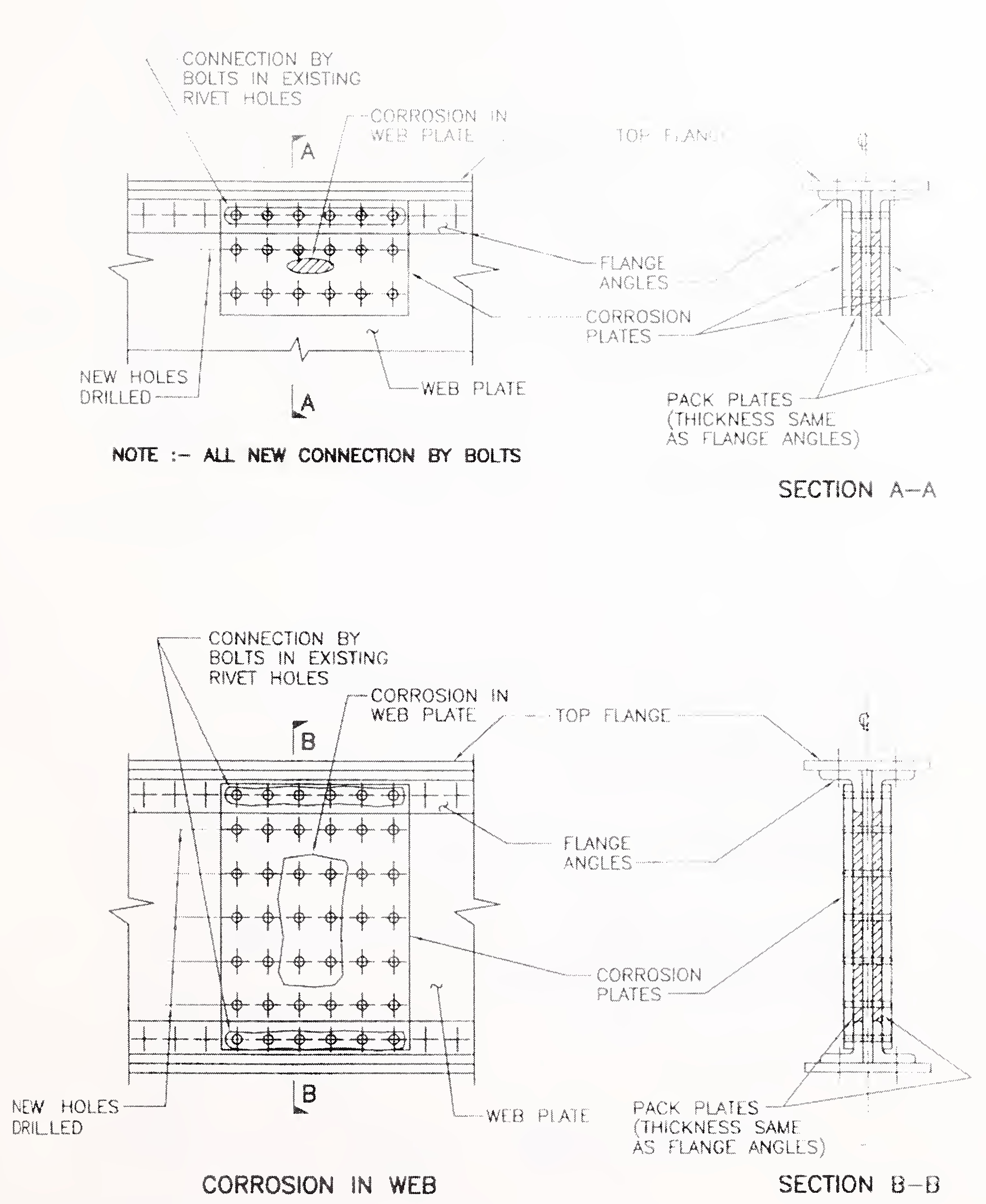
Fig. 2: Rehabilitation of corrosion damaged web plate of riveted girders21
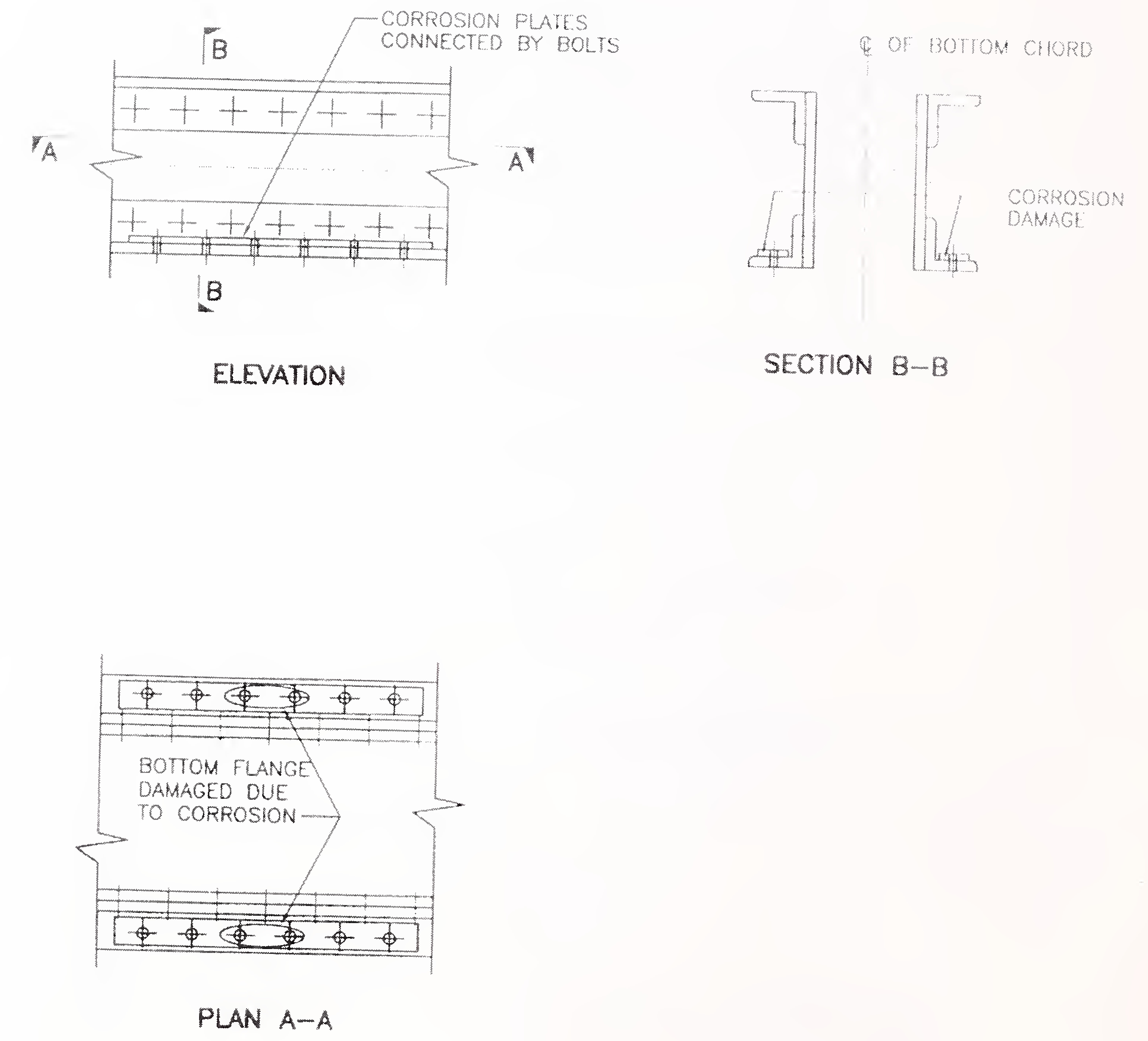
Fig. 3: Rehabilitation of corrosion damaged bottom chord of a truss bridge22
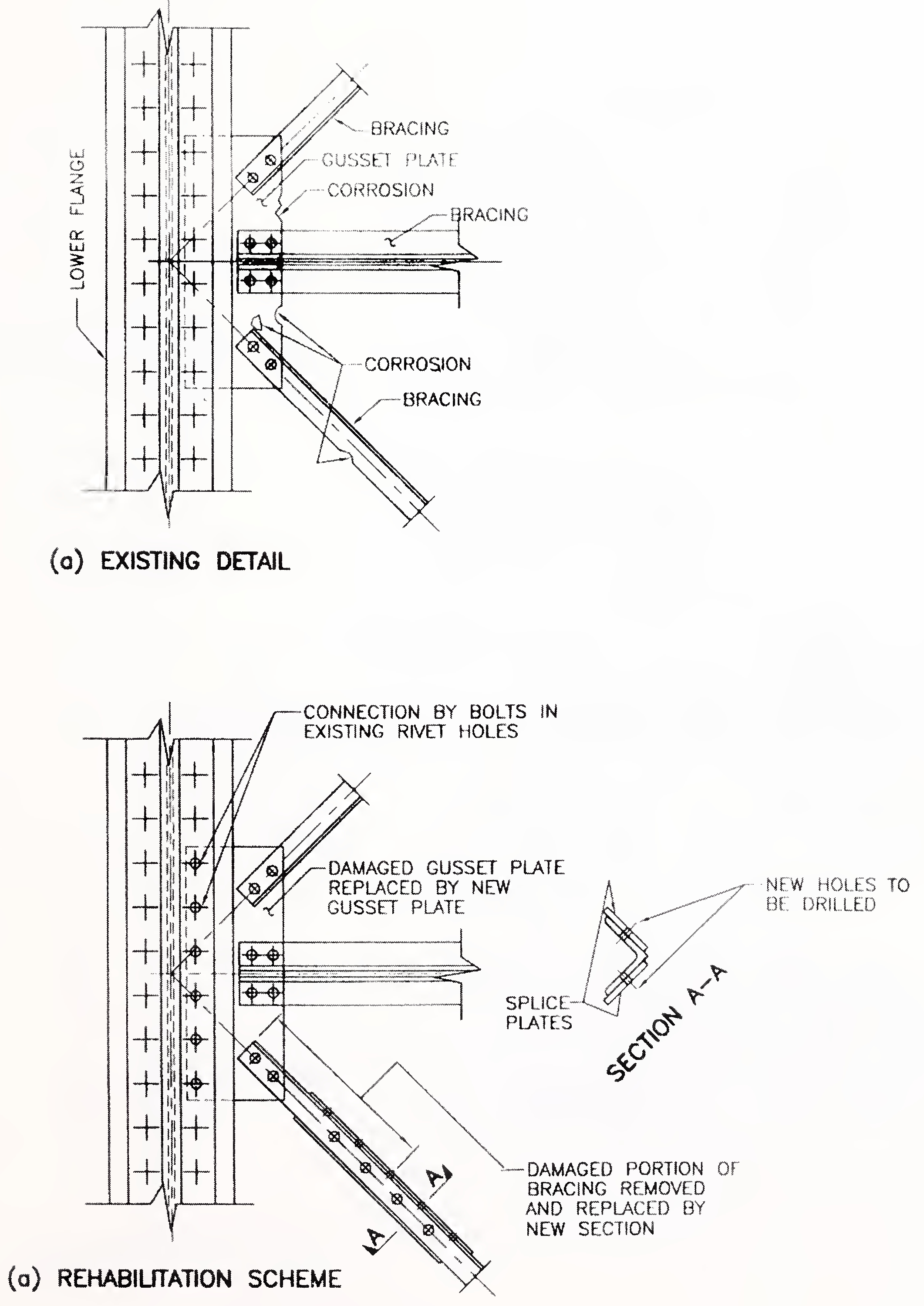
Fig. 4: Rehabilitation of corrosion damaged lateral bracings23
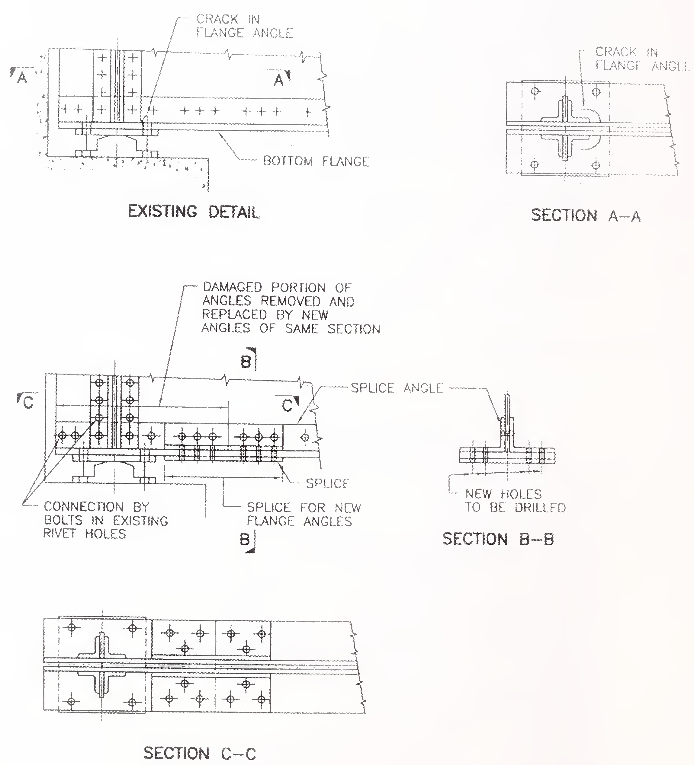
Fig. 5: Retrofit for crack near support in bottom flange angles of a riveted girder24
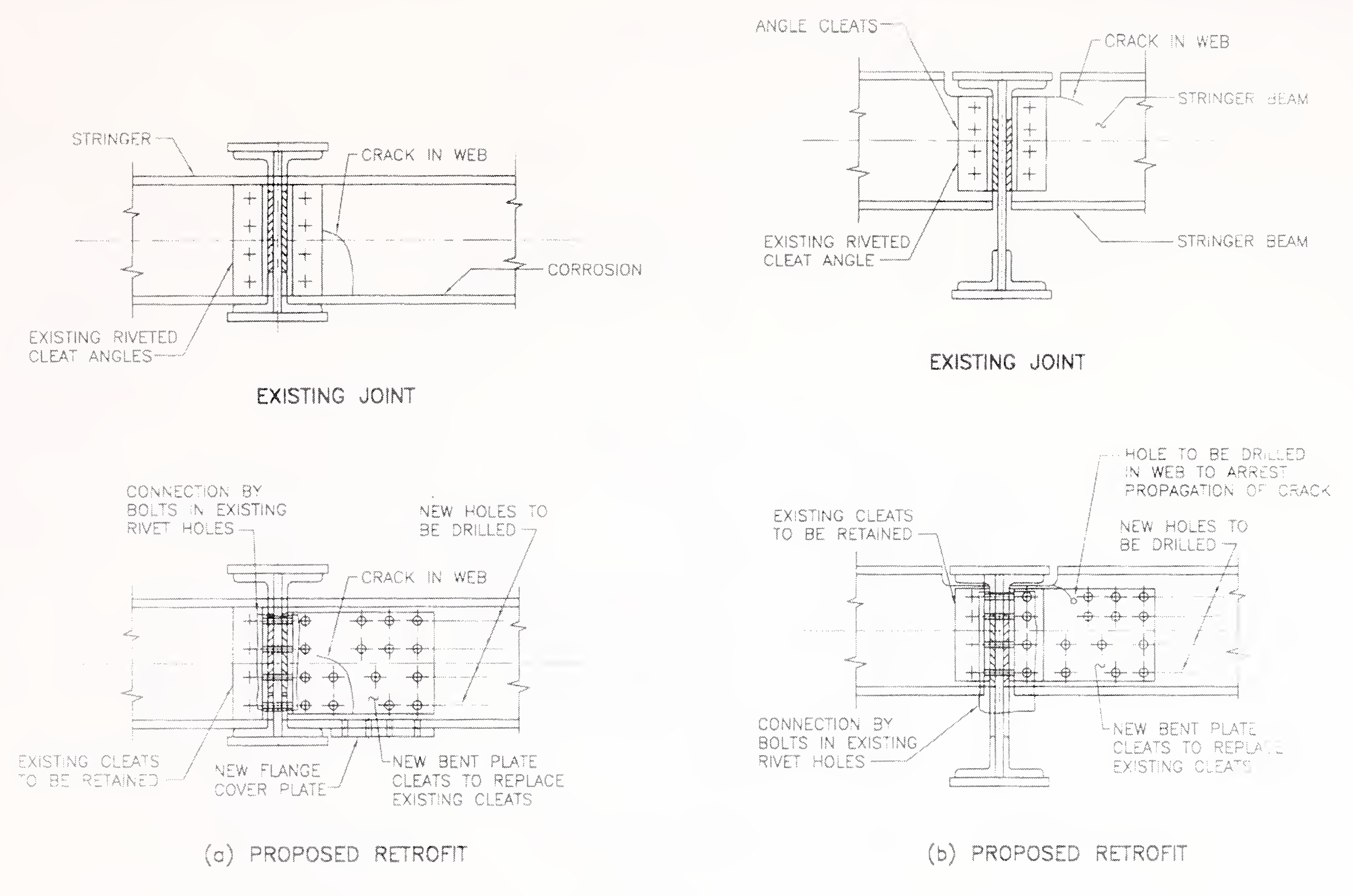
Fig. No.6 Retrofit for crack at end of stringer beam.25
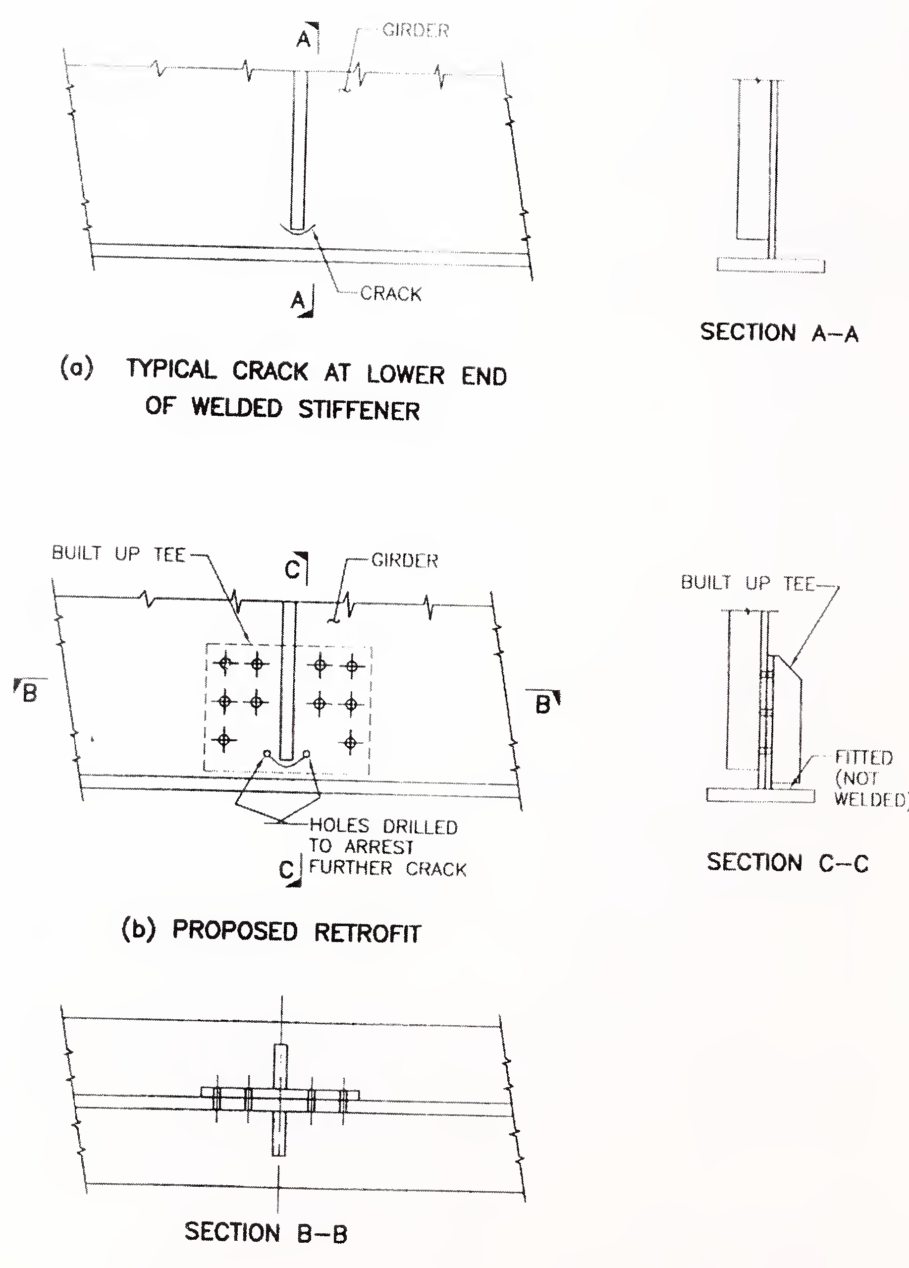
Fig. 7: Rehabilitation of crock in web of welded girder26

NOTIFICATION NO. 62 DATED 18TH JUNE, 2010
Sub: Addendum to IRC:SP:74-2007 "Guidelines for Repair and Rehabilitation of Steel Brides"
IRC:SP:74-2007 "Guidelines for Repair and Rehabilitation of Steel Bridges" was published in October, 2007. The Indian Roads Congress has decided to further amend the above document. Accordingly, the Addendum No. 1 is hereby notified.
This Addendum No. 1 shall be effective from 1 July 2010.

ADDENDUM NO. 1 TO IRC SP 74:2007 "GUIDELINES FOR REPAIR AND REHABILITATION OF STEEL BRIDGES"
| Clause No. | For | Read |
|---|---|---|
| Page 7 Clause 4.2.7 (b) | Non-destructive Testing (NDT) methods Crack testing |
New Test Acoustic Emission Technique Acoustic Emission (AE) technique is one of the latest non-destructive testing (NDT) methods, which can be gainfully used for assessment of the condition of steel bridges. The technique is already in use for monitoring cracks in steel bridges in Western countries. Also, the technique is being used widely for monitoring corrosion and leak detection in aircraft and oil industries as well as in the atomic research centres and rocket industry in India. Acoustic Emission (AE) relates to elastic waves generated by a sudden redistribution of stress in a material. These waves propagate to the surface and are recorded by sensors. AE can result from the initiation and growth of cracks, slip and dislocation movements etc. Initiation and propagation of fatigue cracks can thus trigger AE. Detection and conversion of the elastic waves (related to AE) to electrical signals is the basis ofAE testing. Analysis of these signals yield valuable information regarding the origin and importance of discontinuity in a material. This test can be carried out on line, requiring only limited time. This helps in identifying the affected region of crack including inaccessible areas. AE technique can only gauge the damage qualitatively. In order to get quantitative results (size, depth and overall acceptability), other NDT methods, such as ultrasonic testing, radiographic testing etc. are necessary. Another practical drawback ofAE technique arises from loud extraneous noise in service environments. |