
This library of books, audio, video, and other materials from and about India is curated and maintained by Public Resource. The purpose of this library is to assist the students and the lifelong learners of India in their pursuit of an education so that they may better their status and their opportunities and to secure for themselves and for others justice, social, economic and political.
This item has been posted for non-commercial purposes and facilitates fair dealing usage of academic and research materials for private use including research, for criticism and review of the work or of other works and reproduction by teachers and students in the course of instruction. Many of these materials are either unavailable or inaccessible in libraries in India, especially in some of the poorer states and this collection seeks to fill a major gap that exists in access to knowledge.
For other collections we curate and more information, please visit the Bharat Ek Khoj page. Jai Gyan!
IRC:SP:63-2004
Published by
THE INDIAN ROADS CONGRESS
Jamnagar House, Shahjahan Road,
New Delhi-110011
2004
Price Rs. 200/-
(Plus packing and postage)
PERSONNEL OF THE HIGHWAYS SPECIFICATIONS AND STANDARDS COMMITTEE
(As on 22.5.2004)
| 1. | Indu Prakash* (Convenor) |
Director General (Road Development) & Spl. Secretary to the Govt. of India, Ministry of Road Transport & Highways, Transport Bhavan, New Delhi-110001 |
| 2. | G. Sharan (Co-Convenor) |
Chief Engineer (R&B) S&R, Ministry of Road Transport & Highways, Transport Bhavan, New Delhi-110001 |
| 3. | The Chief Engineer (R&B) S&R (Member-Secretary) |
(G. Sharan) Ministry of Road Transport & Highways, Transport Bhavan, New Delhi-110001 |
| Member | ||
| 4. | A.P. Bahadur | Chief Engineer, Ministry of Road Transport & Highways, Transport Bhavan, New Delhi-110001 |
| 5. | P.K. Chakrabarty | Chief General Manager (NS), National Highways Authority of India, Plot No. G/5-6, Sector 10, Dwarka, New Delhi-110045 |
| 6. | P.K. Datta | Executive Director, Consulting Engg. Services (I) Pvt. Ltd., 57, Nehru Place, New Delhi-110019 |
| 7. | J.P. Desai | Sr. Vice-President (Tech. Ser.), Gujarat Ambuja Cements Ltd., Ambuja House, Ishwarbhuwan Road, Navrangpura, Ahmedabad-380009 |
| 8. | Dr. S.L. Dhingra | Professor, Transportation System, Civil Engg. Department, Indian Institute of Technology, Mumbai, Powai, Mumbai-400076 |
| 9. | D.P. Gupta | DG(RD) (Retd.), E-44, Greater Kailash (Part I) Enclave, New Delhi-110048 |
| 10. | S.K. Gupta | Chief Engineer, PWD, Almora |
| 11. | R.K. Jain | Chief Engineer (Retd.), House No. 452, Sector 14, Sonepat-131001 |
| 12. | Dr. S.S. Jain | Professor & Coordinator (COTE), Deptt. of Civil Engg., Indian Institute of Technology, Roorkee, Roorkee-247667 |
| 13. | Dr. L.R. Kadiyali | Chief Executive, L.R. Kadiyali & Associates, X-15 (First Floor), Hauz Khas, New Delhi-110016 |
| 14. | Prabha Kant Katare | Joint Director (PI), National Rural Road Dev. Agency (Min. of Rural Dev.) NBCC Tower, 5th Floor, Bhikaji Cama Place, New Delhi-110066 |
| 15. | J.B. Mathur | Chief Engineer (Retd.), H. No. 77, 1st Floor, Sector 15A, Distt. Gautam Budh Nagar, Noida-201301i |
| 16. | H.L. Mina | Chief Engineer-cum-Addl. Secy. to the Govt. of Rajasthan, P.W.D., Jacob Road, Jaipur-302006 |
| 17. | S.S. Momin | Secretary (Works), Maharashtra P.W.D., Mantralaya, Mumbai-400032 |
| 18. | A.B. Pawar | Secretary (Works) (Retd.), C-58, Abhimanshree Housing Society, Off Pashan Road, Pune-411008 |
| 19. | Dr. Gopal Ranjan | Director, College of Engg.,.Roorkee, Post Box No. 27, K.M. Roorkee-Hardwar Road, Vardhman Puram, Roorkee-247667 |
| 20. | S.S. Rathore | Secretary to the Govt. of Gujarat, R&B Department, Block No. 14/1, Sardar Bhavan, Sachivalaya, Gandhinagar-382010 |
| 21. | Arghya Pradip Saha | Sr. Consultant, M-504, Habitat (Highway) CGHS, B-19, Vasundhra Enclave, Delhi |
| 22. | S.C. Sharma | DG(RD) & AS, MORT&H (Retd.), 175, Vigyapan Lok, 15, Mayur Vihar Phase-I Extn. (Near Samaehar Apartments), Delhi-110091 |
| 23. | Prof. P.K. Sikdar | Director, Central Road Research Institute, P.O. CRRI, Delhi-Mathura Road, New Delhi-110020 |
| 24. | Dr. C.K. Singh | Engineer-in-Chief-cum-Addl. Comm-cum.-Spl. Secy. (Retd.), House No. M-10 (D.S.) Hermu Housing Colony, Main Hermu Road, Ranchi (Jharkhand) |
| 25. | Nirmal Jit Singh | Member (Tech.), National Highways Authority of India, Plot No. G/5-6, Sector 10, Dwarka, New Delhi-110045 |
| 26. | A.V. Sinha | Chief General Manager, National Highways Authority of India, Plot No. G/5-6, Sector 10 Dwarka, New Delhi-110045 |
| 27. | N.K. Sinha | DG(RD & SS, MORT&H (Retd.), G-1365, Ground Floor, Chittranjan Park, New Delhi-110019 |
| 28. | V.K. Sinha | Chief Engineer, Ministry of Road Transport & Highways, Transport Bhavan, New Delhi-110001 |
| 29. | K.K. Sarin | DG(RD) & AS, MOST (Retd.), S-108, Panehshila Park, New Delhi-110017 |
| 30. | T.P. Velayudhan | Addl. D.G.B.R., Directorate General Border Roads, Seema Sadak Bhavan, Ring Road, Delhi Cantt., New Delhi-110010 |
| 31. | Maj. V.C. Verma | Executive Director-Marketing, Oriental Structural Engrs. Pvt. Ltd., 21, Commercial Complex, Maleha Marg, Diplomatic Enel., New Delhi-110021 |
| 32. | The Chief Engineer (NH) | (B. Prabhakar Rao), R&B Department, Errum Manzil, Hyderabad-500082ii |
| 33. | The Chief Engineer (Plg.) | (S.B. Basu), Ministry of Road Transport & Highways, Transport Bhavan, New Delhi-110001 |
| 34. | The Chief Engineer (Mech.) | (V.K. Saehdev), Ministry of Road Transport & Highways, Transport Bhavan, New Delhi-110001 |
| 35. | The Chief Engineer (Mech.) | PWD, G Block, 4th Floor, Writers’ Building, Kolkata-700001 |
| 36. | The Chief Engineer (NH) | (Ratnakar Dash), Sachivalaya Marg, Unit IV, Bhubaneswar-751001 Distt. Khurdha (Orissa) |
| 37. | The Engineer-in-Chief | U.P. P.W.D., 96, M.G. Road, Lucknow-226001 |
| 38. | The Chief Engineer | National Highways, PWD Annexe, K.R. Circle, Bangalore-560001 |
| Ex-Officio Members | ||
| 39. |
President, Indian Road Congress | (S.S. Momin), Secretary (Works), PWD Sachivalaya, Mumbai-400032 |
| 40. | The Director General (Road Development) & Special Secretary |
(Indu Prakash), Ministry of Road Transport & Highways, Transport Bhavan, New Delhi-110001 |
| 41. | Secretary,Indian Roads Congress | (R.S. Sharma), Indian Roads Congress, Jamnagar House, New Delhi-110011 |
| Corresponding Members | ||
| 1. | M.K. Agarwal | Engineer-in-Chief, Haryana PWD (Retd.) House No. 40, Sector 16, Panchkula-134113 |
| 2. | Dr. C.E.G. Justo | Emeritus Fellow, 334, 25th Cross, 14th Main, Banashankari, 2nd Stage, Bangalore-560070 |
| 3. | M.D. Khattar | Executive Director, Hindustan Construction Co. Ltd., Hineon House, Lal Bahadur Shastri Marg. Vikhroli (W), Mumbai-400083 |
| 4. | Sunny C. Madathil | Director (Project), Bhagheeratha Engg. Ltd., 132, Panampily Avenue, Cochin-682036 |
| 5. | N.V. Merani | Principal Secretary, Maharashtra PWD (Retd.), A-47/1344, Adarsh Nagar, Worli, Mumbai-400025iii |
* ADG(R) being not in position, the meeting was presided by Shri Indu Prakash, DG(RD) & Spl. Secretary to the Govt. of India, MORT&H
GUIDELINES FOR THE USE OF INTERLOCKING CONCRETE BLOCK PAVEMENTS
The Rigid Pavement Committee (H-5) in its meeting held on the 28th November, 2003 discussed the draft Guidelines for the Use of Interlocking Concrete Block Pavements and desired to recirculate the modified document in light of the suggestions made by the members to improve the document. Accordingly, the modified document was circulated and discussed during the meeting of H-5 Committee (Personnel given below) held on the 8th March, 2004 and the document was approved with certain modifications :
| Rigid Pavement Committee (H-5) | |
| Dr. L.R. Kadiyali | Convenor |
| The CE (R&B) S&R, MORT&H (G. Sharan) |
Co-Convenor |
| M.C. Venkatesha | Member-Secretary |
| Members | |
| H.S. Chahal | S.C. Sharma |
| M.L.N. Chary | Brajendra Singh |
| R.P. Indoria | V.K. Sinha |
| R.K. Jain | Dr. R.M. Vasan |
| Dr. B.B. Pandey | A Rep. of MSRDC (P.D. Kulkarni) |
| Y.R. Phull | A Rep. of DGBR (M.S. Sodhi) |
| S.P. Rastogi | A Rep. of NCC&BM (R.C. Wason) |
| S.M. Sabnis | A Rep. of CRRI (Satandar Kumar) |
| Director, HRS (K. Thangarasu) | |
| Ex-Officio Members | |
| President, IRC (S.S. Momin) |
DG(RD) & SS (Indu Prakash) |
| Secretary, IRC (R.S. Sharma) |
|
| Corresponding Members | |
| K.B. Bhaumik | Prof. K.V. Krishna Rao |
| D.C. De | A.U. Ravi Shankar |
| Dr. (Mrs.) Vandana Tare1 | |
The draft was discussed by the Highways Specifications and Standards Committee during its meeting held on the 22nd May, 2004 and the draft was approved subject to modifications in light of the comments made by its members. The modified document as received from the Convenor, H-5 Committee was placed before the Executive Committee in its meeting held on 25th May, 2004. The Executive Committee considered the Guidelines for being placed before the Council. The Council in its 172nd Meeting held at Nainital (Uttaranchal) on the 12th June, 2004 approved the document for publication subject to modification in light of the comments/suggestions given by the participants. The document has been modified suitably by Dr. L.R. Kadiyali, Convenor, H-5 Committee.
Interlocking Concrete Block Pavements have been extensively used in a number of countries for quite sometime. Considering their advantages and potential for use, the guidelines have been prepared for the design and construction of such pavements, giving the suggested applications, design catalogues, construction practices and specifications for their use.
Interlocking Concrete Block Pavements have been found to have applications in several situations. Such as :
Advantages and Limitations of Interlocking Concrete Block Pavements.
The blocks can be interlocking horizontally and vertically, as shown in Fig 1.
Present day interlocking blocks have evolved in shape after observing their performance. The three phases in the evolution of the shape of the blocks are shown in Fig. 2.
The rectangular shape shown in Fig. 2(i) is the shape which was intended for imitating the stone set blocks. The shape shown in Fig. 2(ii) is an improved version with many dentated faces for better contact between adjoining blocks thus enhaneing the interlocking effect and friction between them. This helps in increasing the shear strength of the block system and thus the load dispersal capacity. The block shown in Fig. 2(iii) is a further improvement over dentated rectangular block. The block shown in Fig. 2(iv) gives still better interlock and is suitable for fully mechanized paving.
The dentated blocks further can be grouped as shown in Fig. 3 into three categories as under:
| Category A: | Dentated units are designed to key into each other on all four faces and which, by their plan geometry when keyed together, resist the widening of the joint. These blocks are generally capable of being laid in herringbone bond pattern (as explained in Section 8). |
| Category B: | These blocks are dentated on only two sides. Their dimensional accuracy of laying helps in bringing about the interlock effect on other faces. Generally, with some exceptions, these blocks can only be laid in stretcher bond, as explained in Section 8. |
| Category C: | These are not dentated type but depend on dimensional accuracy for interlocking effect. These blocks can be laid only in a stretcher bond. |
The overall dimension of blocks used in various parts of the world ranges as under :
Top surface area : 5,000 to 60,000 mm2
Horizontal dimension not exceeding : 28 cm
Thickness : Between 60 to 140 mm
Length/Thickness : ≥ 4
In addition to regular blocks described above, supplementary blocks of half size would be required for paving purpose. In the case of rectangular blocks, more number of half blocks would be generally required than other category of blocks.4
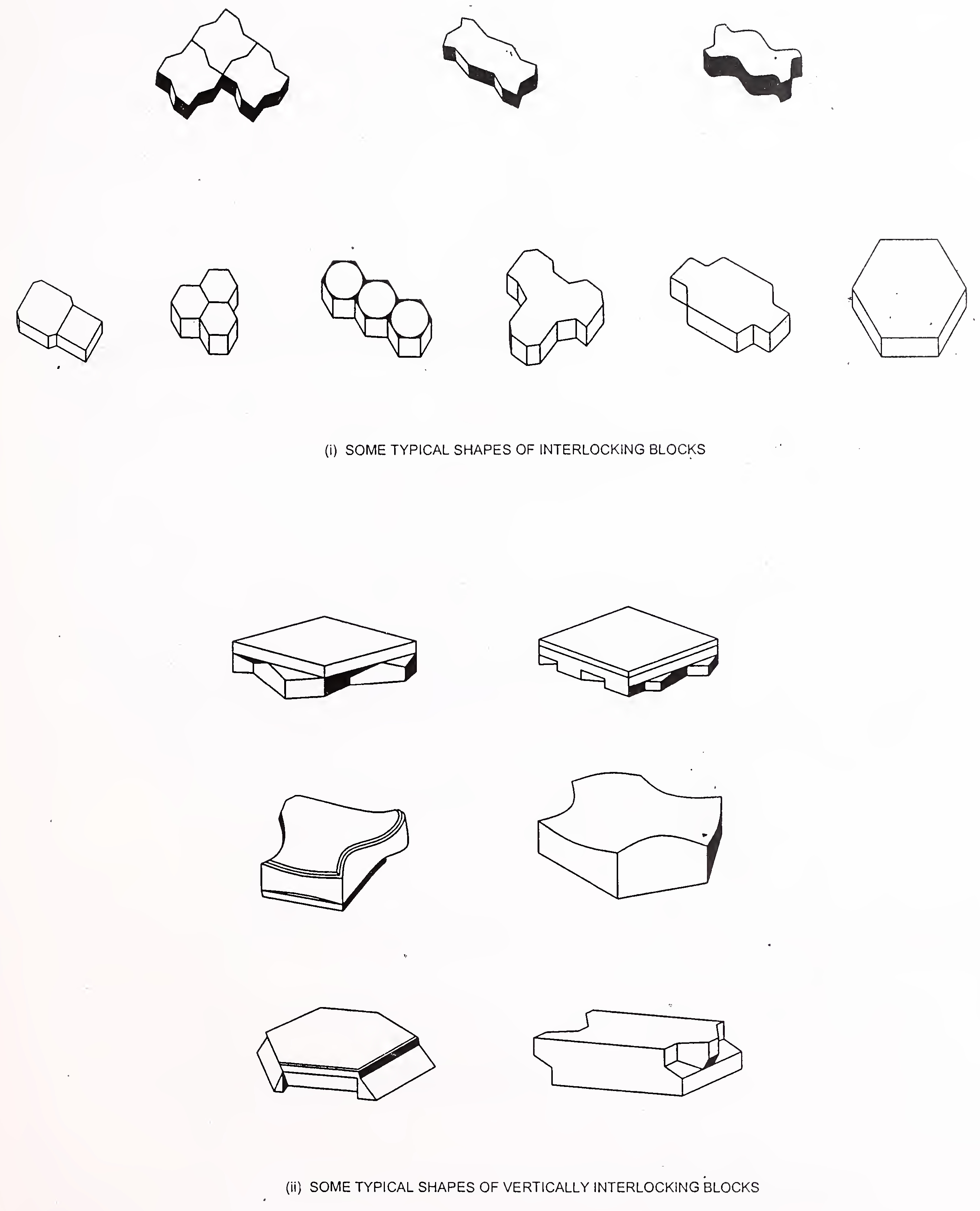
Fig. 1. Some shapes of interlocking blocks5
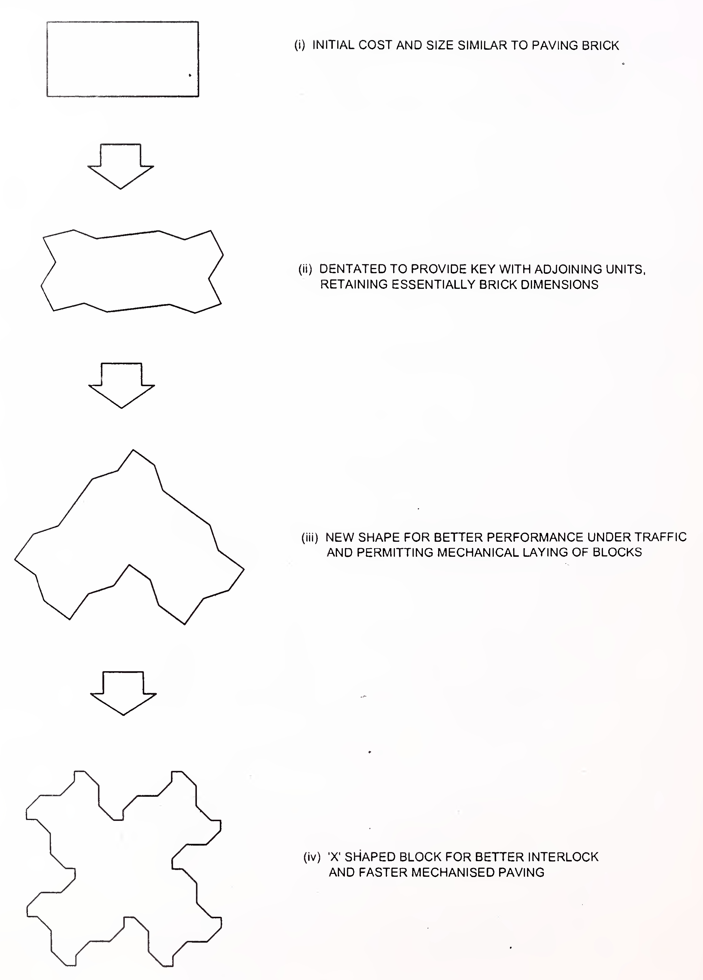
Fig. 2. Basic shapes of blocks6
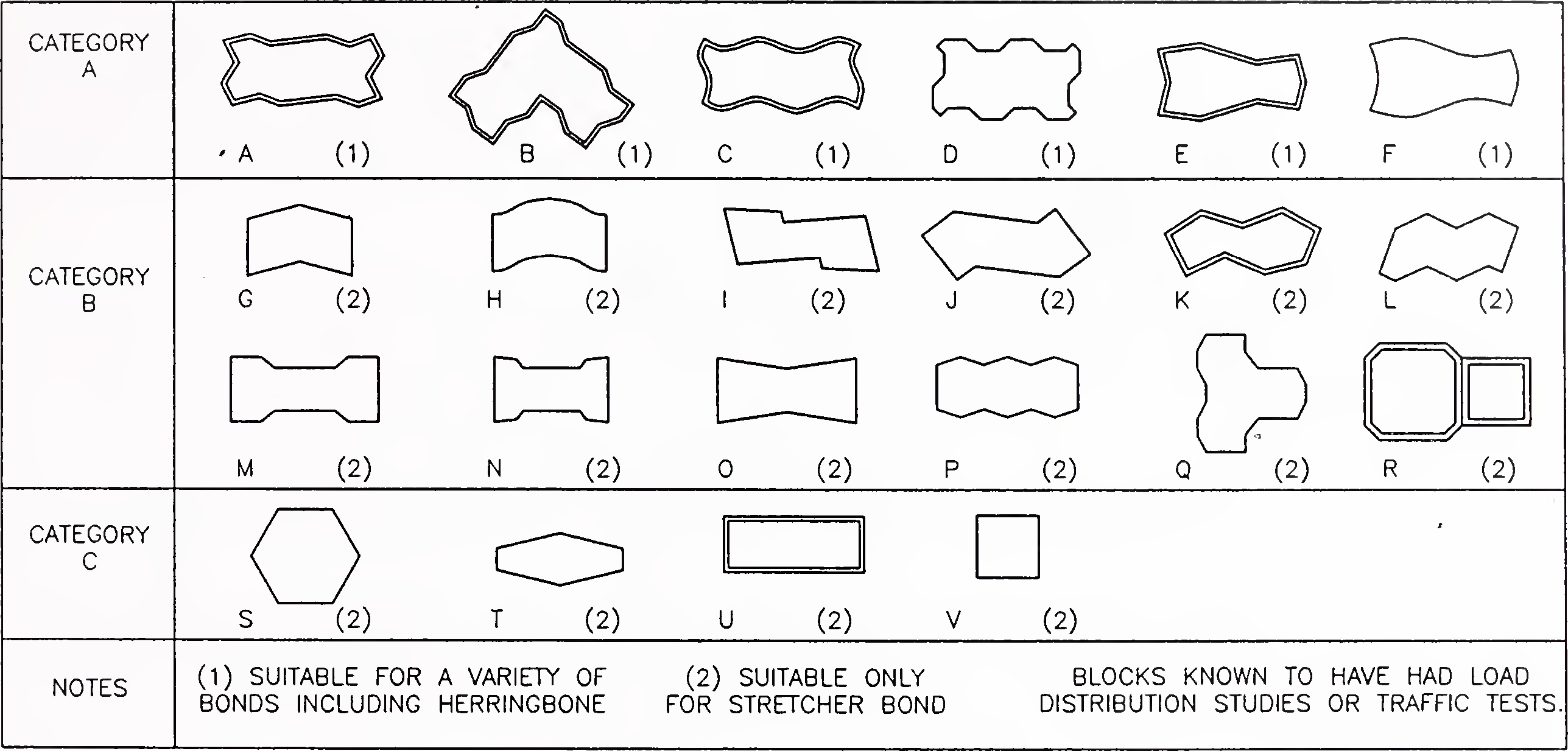
Fig. 3. Different categories of blocks
Special Grass Blocks
For improving aesthetic looks of paved areas, architects have been making use of block pavement extensively. The numerous paving blocks and their joints mellow down the harshness created by large transverse joints formed in conventional concrete pavement.
For improving aesthetics further, grass blocks have been developed. These when constructed in a grid formation allow space in the pavement for growing grass as shown in Fig. 4. These are best suited for walkways, driveways, etc. Coloured blocks also add to the aesthetic beauty.
Except for the top wearing part of the pavement, the base and sub-base layers are similar to the conventional flexible or rigid pavement. Depending upon the load coming on them, the composition of the pavement differs.
A few typical compositions normally used are given in Figs. 5 and 6.
Interlocking concrete blocks come in different thicknesses. These blocks serve as wearing surface but at the same time help in reducing the stresses imposed on subgrade and also help in resisting pavement deformation and elastic deflections similar to the base course of a flexible pavement.7
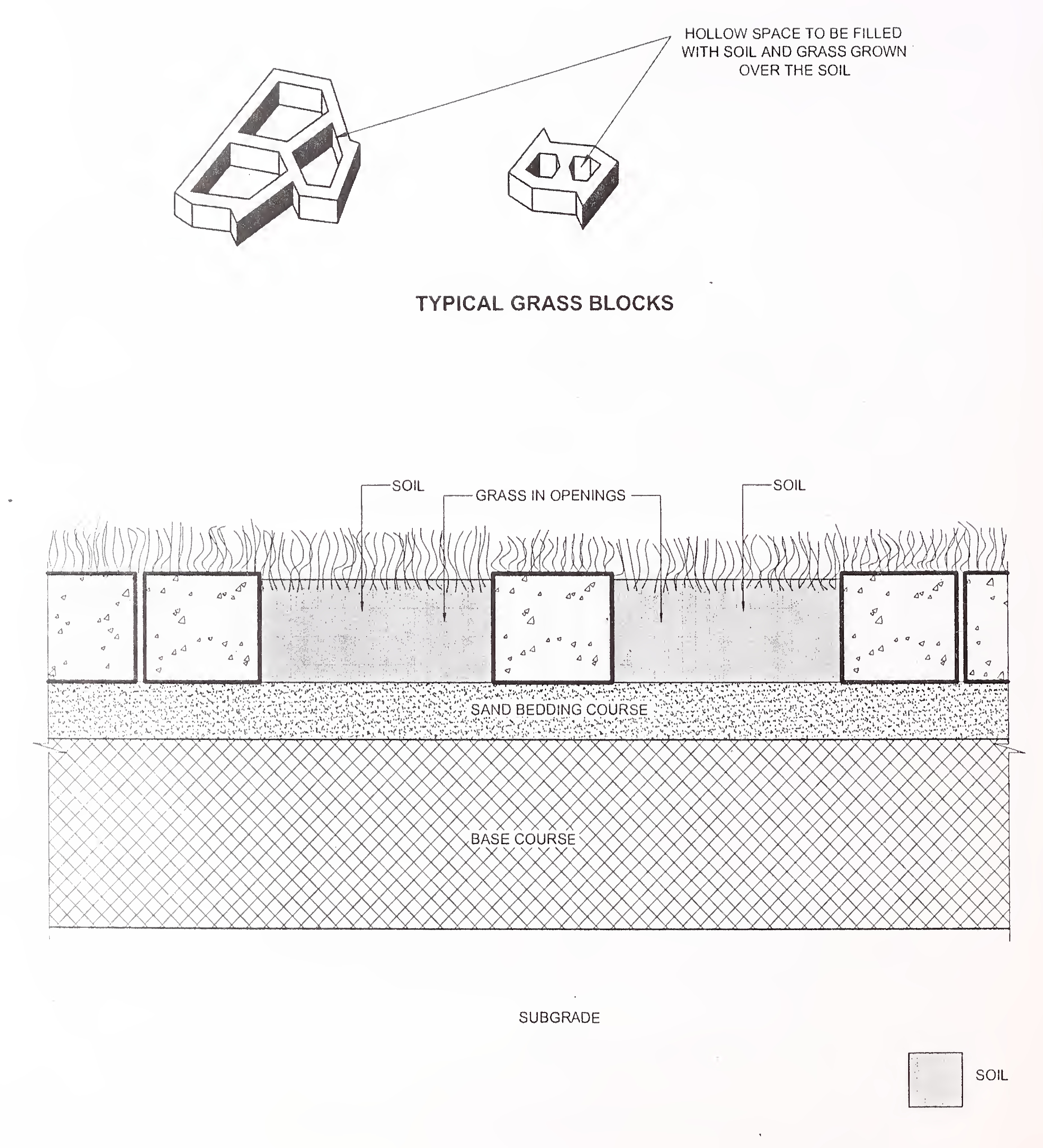
Fig. 4. Grass blocks and the construction technique8
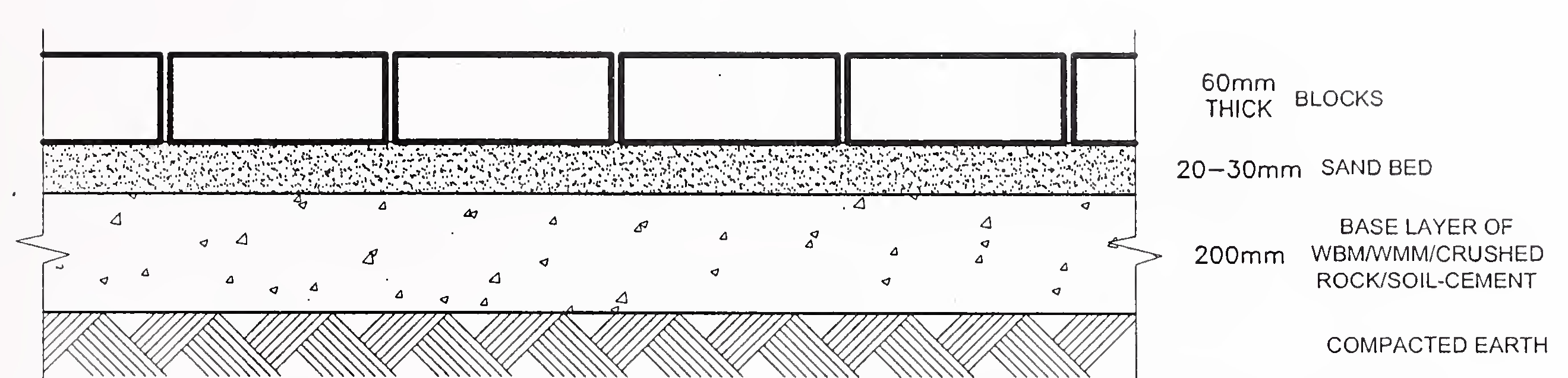
Fig. 5. A Typical cross section of block pavement used in sidewalks/foot-paths/car-parks/cycle track
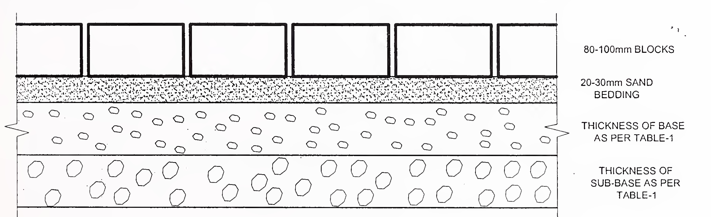
Fig. 6. A typical cross section of block pavement for heavily trafficked roads
For Category 'A' blocks used for light traffic, such as, pedestrians, motor cars, cycles, etc., a block thickness of 60 mm is adequate; for medium traffic, a thickness of 80 mm is generally used; for heavily trafficked roads, Category 'B' blocks of the thickness 100-120 mm are used. Thick blocks are best suited where high volumes of turning movements are involved.
Non-uniformity in thickness of blocks affects the evenness of the surface. A block pavement which is initially paved to a levelled surface will settle unevenly with the movement of vehicles, as shown in Fig. 7. In view of this, all blocks should be of the same thickness, with a maximum allowable tolerance limits of ± 3 mm. Similarly, variations in length and width of blocks should be limited to ± 2 to 3 mm for ensuring uniform joint width and avoiding staggering effect.
A layer of sand bedding is provided between block pavement and base/sub-base for the following reasons:
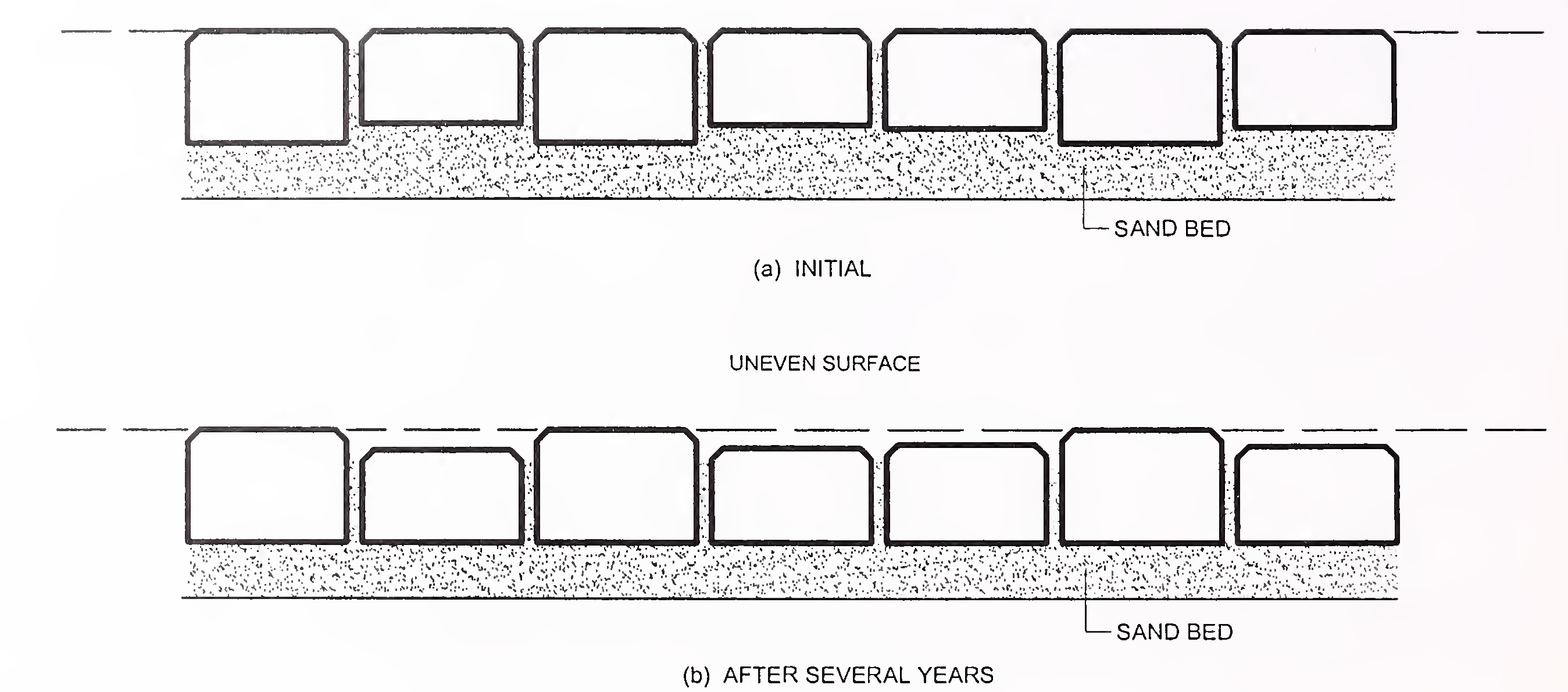
Fig. 7. Effect of thickness variations in paving blocks
The sand bed should not be too thick lest it would be difficult to control the surface level of the blocks. A layer thickness of 20 to 40 mm is found to be satisfactory.
For block pavement to perform satisfactorily, it is necessary that the lower layers are profiled to proper level and finish and that the bedding sand layer is of uniform thickness. Varying thickness of sand bed ultimately results in uneven surface of the pavement.
The grading and quality of sand is very important for the block pavement to perform satisfactorily. The sand used should be free from plastic clay and should be angular type. It should not be of degradable type for e.g., sand produced from lime stone, etc. is likely to get powdered under the loading.
Joints between blocks are filled by fine sand. Normally, the bottom 20 to 30 mm of the joint gets filled with bedding sand, whereas, the remainder space has to be filled with jointing sand by brooming it from the top. The joints are normally 2 to 4 mm wide.
These layers are the important structural layers of a block pavement. The materials used for base construction consist of either bound material like lean concrete or soil-cement or bituminous layers or unbound materials like wet mix macadam or WBM. The sub-bases are generally of granular material. The sub-base can function as drainage layer as well, provided proper disposal arrangement for water is made. The base course layer is normally provided where heavy vehicular traffic is likely.
Besides intensity of loading, the type of soil encountered determines the type and thickness of base and sub-base. For weak subgrade soils like clays, where ground water table is shallow, bound bases are preferred.10
Concrete blocks on trafficked pavements tend to move sideways and forward due to braking and manoeuvring of vehicles. The tendency to move sideways has to be counteracted at the edges by special edge blocks and kerbs. The edge blocks should be designed such that the rotation or displacement of blocks is resisted. These are to be made of concrete of high strength to withstand the traffic wheel loading without getting damaged. These members should be manufactured or constructed in-situ to have at least a 28 day compressive strength of 30 MPa or flexural strength of 3.8 MPa. As far as possible the edge blocks should have vertical face towards the inside blocks. A few typical edge blocks are also shown in Fig. 8.
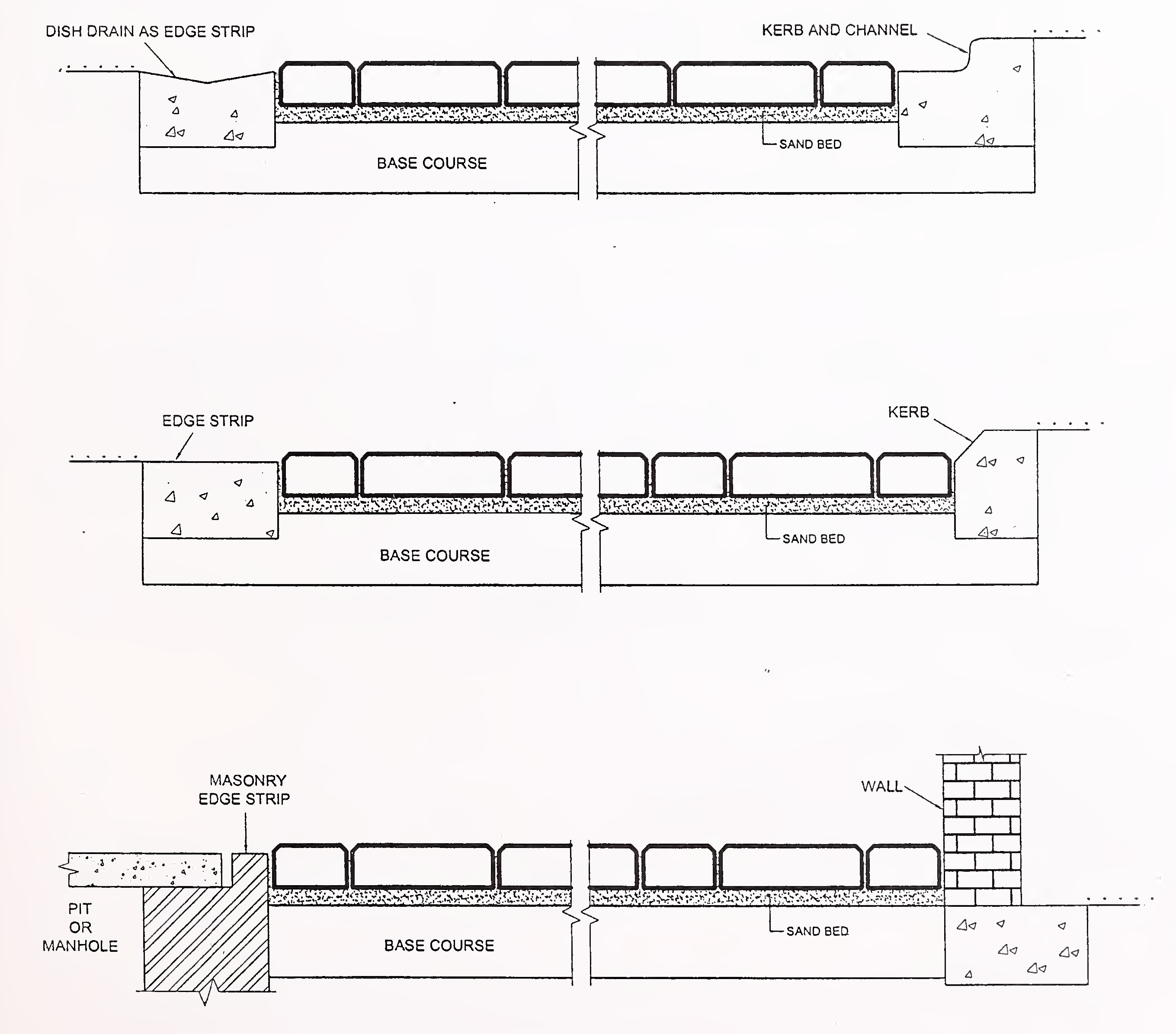
Fig. 8. Edge restraints11
The road kerbs provided on the edge of the road also serve the purpose of edge blocks as shown in Fig. 8. In case the kerbs are not provided, it has to be replaced by edge strips.
Design procedures have been developed by agencies abroad based on successful performance, or mechanistic principles. They cover a variety of roads ranging from the lightly trafficked to the heavily trafficked. In the absence of research in India, it is recommended that the catalogue of designs given subsequently may be used.
Pedestrian side-walks, footpaths, cycle tracks, car parks and malls are lightly trafficked. In such situations, the pavement can consist of blocks 60 mm thick laid over a sand bedding 20-30 mm and a base course 200 mm thick. The base course can be in WBM/WMM/crushed stone/soil-cement. This design can be adopted for the range of subgrade soils met with in India. A typical cross-section is given in Fig. 5.
City streets and highway sections subjected to commercial traffic (trucks and buses) require a heavier section. Though design methods based on empirical approach and mechanistic behaviour are available, enough work has not been done in India to evolve the country's own design procedure. In the absence of such knowledge, the ad-hoc design catalogues based on international experience as given in Table 1 are suggested for adoption. A design life of 20 years can be considered for determining the repetitions of standard axles.
For block pavements for industrial applications like container yard and port wharf and roads and warehouses the following thickness is recommended, based on international experience:
| Block | : | 100 mm |
| Sand Bedding | : | 30-50 mm |
| Hydraulically bound base | : | 300 mm |
| Granular sub-base (out of which the bottom 150 mm is a drainage layer) | : | 300 mm |
The quality of materials, cement concrete strength, durability and dimensional tolerances, etc. are of great importance for the satisfactory performance of block pavements. These aspects and the12
| Traffic and Road Type | Subgrade CBR (%) | ||
|---|---|---|---|
| Above 10 | 5-10 | ||
| • Cycle Tracks, Pedestrian Footpaths | Blocks | 60 | 60 |
| Sand Bed | 20-30 | 20-30 | |
| Base | 200 | 200 | |
| • Commercial Traffic Axle Load Repetitions less than 10 msa | Blocks | 60-80 | 60-80 |
| Sand Bed | 20-40 | 20-40 | |
| • Residential Streets | WBM/WMM Base | 250 | 250 |
| Granular Sub-base | 200 | 250 | |
| • Commercial traffic Axle Load Repetitions 10-20 msa | Blocks | 80-100 | 80-100 |
| Sand Bed | 20-40 | 20-40 | |
| • Collector Streets, Industrial Streets, Bus and Truck Parking Areas | WBM/WMM Base | 250 | 250 |
| Granular Sub-base | 200 | 250 | |
| • Commercial traffic Axle Load Repetitions 20-50 msa | Blocks | 80-100 | 80-100 |
| Sand Bed | 20-40 | 20-40 | |
| • Arterial Streets | WBM/WMM Base | 250 | 250 |
| or WBM/WMM Base | 150 | 150 | |
| and DLC over it* | 75 | 75 | |
| Granular Sub-base | 200 | 250 | |
| Notes : 1. Thickness of layers given above are in mm. 2 Granular sub-base should have at least 150 mm layer at the bottom which is drainable. 3. A typical cross-section is given in Fig. 6. 4. If the subgrade soil has a CBR of less than 5, it should be improved by suitable stabilisation technique to bring the CBR value to 5. 5. msa denotes repetitions in million standard axles * in case of roads having inadequate drainage or heavy rainfall areas (above 1500 mm per annum) | |||
block manufacturing process itself, which immensely influences the quality of paving blocks, are broadly outlined in the subsequent paragraphs. The desired engineering properties of bedding/jointing sand layer beneath the block, the base course and sub-base materials are also described.13
The commonly used processes for the manufacture of pre-cast cement concrete paving units require dry, low-slump mixes. The desired characteristics of the mix are as under:
| Water/cement ratio | : | 0.34 to 0.38 |
| Water content of the mix | : | 5 to 7% of total mix |
| Quantity of cement in mix | : | Generally not less than 380 kg/m3 depending on the equipment being used for block making. Upper limit of cement shall not be more than 425 kg/m3. Fly ash also can be used in the mix, replacing Ordinary Portland Cement to an extent of 35 per cent. |
The above values are for general guidance only. The actual mix design has to be made to suit each individual requirement.
| Aggregate/cement ratio | : | 3:1 to 6:1 |
| Aggregates | : | Should be sound and free from soft or honeycombed pieces. The proportion of coarse aggregate in the mix is typically 40 per cent and the fine aggregate (sand) 60 per cent. The size of coarse aggregate should lie between 6 mm and 12 mm and the gradation should be in the recommended range for cement concrete mixes in general. |
| Strength | : | In general terms, the paving block must have adequate strength to withstand handling, construction stresses and effects of traffic, though the strength as such is not considered a vital factor in the satisfactory performance of a block pavement. However, it is suggested that the minimum compressive strength of a single block should be above 30 MPa. |
| Addition of Pigments | : | To provide the desired colour to paving blocks, appropriate type and amount of pigments are added during mixing, in the form of powder or slurry. Although organic pigments render brighter colours than inorganic pigments, the former are adversely affected by the alkaline environment of concrete and do deteriorate with time. Inorganic pigments, mostly metal oxides, are more durable and hence preferred for consistency and purity. Saturation of colour takes place with a pigment volume of around 5 to 9 per cent of cement content. Pigments should be finer than cement (fineness value between 2 and 15 m2/gm). For the same slump, addition of pigments14 requires increase in mixing water, which in some cases may lead to lowering of flexural and compressive strength of concrete; therefore, suitable adjustments in mix proportions may become necessary. |
| Other Additives | Under special circumstances, super-plasticizers at around 0.4 per cent of cement by weight may be added for high early strength. Water repellant admixtures of calcium stearate are sometimes used to reduce water absorption. Air entraining agents, when added to the mix, cause some reduction in the needed amount of cement. Further reduction is achieved by substituting part of the cement with blast-furnace slag or pozzolanas like flyash; besides reducing cost, these also control "efflorescence" (surface deposition of salts as a result of water movement upwards). |
The method of manufacture of paving blocks has an important bearing on the quality, durability and level of finish - dimensional tolerance, etc. all of which reflect on the ultimate performance of the block pavement during service. At the very outset, therefore, it is to be emphasized that hand-casted concrete blocks are unacceptable for use and that an appropriate plant should be used which would make it possible to apply high pressure together with controlled vibration. Adaptation of production facilities designed for high quality hollow masonry blocks, though feasible, is not as economical and as efficient as the use of purpose designed machinery for paving block manufacture. Essentially, the manufacturing process involves compacting concrete, in a steel mould clamped to a vibrating table, by hydraulic pressure.
Concrete is fed into the mould from a hopper by a drawer - if a second hopper is added, a block can be made of two kinds of concrete having "backing" and "facing" surfaces. In the "facing" of the block, the top 5 mm has greater amounts of cement and sand to make it more durable and skid-resistant, and extra pigment is added for the coloured face vis-a-vis the rest of the block. In the first stage of compaction, pre-vibration is effected by running the vibrators attached to the vibratory table, the frequency generally being in the range of 50 to 100 Hz. In the second stage of compaction, compression pressure is applied to the tamper heads, also fitted with vibrators for a high level of surface finish. Blocks are extruded from mould by forcing down the tamper heads, after the vibrating table is disengaged from the mould. The blocks thus prepared are stacked either in a single layer or multiple layers for curing, depending on the plant used being single layer or multi-layer.
For normal paving work, the length of a paving block should ordinarily be not greater than twice the mean width; the thickness is a minimum of 60 mm; the maximum length generally not exceeding 280 mm; the width generally is in the range 75 to 140 mm with a maximum chamfer of 10 mm (preferably chamfer should be in the range 3-5 mm). The sides of the block should be perpendicular15
to the top and bottom faces except that the top edge may be chamfered. The blocks should have the following dimensional tolerances:
| Plan dimensions | ± | 2 mm |
| Thickness | ± | 3 mm |
To ensure durability, the average water absorption in a block should not exceed 5 per cent; and for cold regions in a standard freeze-thaw durability test, the weight loss should not exceed 1 per cent.
In situations, where parts of blocks are to be used e.g., around manholes, the block should be purpose-cut at site.
It is to be recognized that variations in the thickness of blocks used for a paving job can be a major cause for the loss of surface profile, as shown in Fig. 7 on an exaggerated scale. In the interest of maintaining a good surface profile, the block thickness should be controlled carefully; this can be done to advantage by adopting multi-layer method of manufacture of paving blocks, which reduces the variation in block thickness.
Annexure give suggested technical specifications for laying block pavements.
It is well established that if proper attention is not paid to the quality of bedding sand, and if the thickens of the bedding sand layer is not uniform enough, serious irregularities in surface profile can result; excessive differential deformation and rutting can occur early in service life of the block pavement. The desired gradation of bedding sand should be as under :
| IS Sieve Size | Percent Passing |
| 9.52 mm | 100 |
| 4.75 mm | 95-100 |
| 2.36 mm | 80-100 |
| 1.18 mm | 50-95 |
| 600 micron | 25-60 |
| 300 micron | 10-30 |
| 150 micron | 0-15 |
| 75 micron | 0-10 |
Care should be taken to see that single-sized or gap graded sands or sands with excessive amount of fines or plastic fines should not be used. The shape of sand particles should preferably be sharp rather than rounded, since the sharp sands possess higher strength and resist the migration of sand from under the block to less frequently trafficked areas. Eventhough sharp sands are relatively more difficult to compact than rounded sands., the use of sharp sands should be preferred for the more heavily trafficked pavements. The bedding sand should be free of deleterious materials.16
The gaps in between two paving blocks (typically about 3 mm wide) need to be filled by sand, relatively finer than the bedding sand. The desired gradation for the joint filling sand is as under:
| IS Sieve Size | Per cent Passing |
| 2.36 mm | 100 |
| 1.18 mm | 90-100 |
| 600 micron | 60-90 |
| 300 micron | 30-60 |
| 150 micron | 15-30 |
| 75 micron | 0-10 |
It is necessary to restrict the fines (silt and/or clay) to 10 per cent, since excessive fines make joint filling very difficult. Similarly, it is not advisable to use cement in the joint filling sand which will not only make it difficult to completely fill the joints but would also adversely affect the desired flexibility characteristics of the paving block layer. The joint filling sand should be as dry as possible; otherwise complete filling of joints will be difficult. To overcome the problem of efflorescence on the surface of paving block layer, the joint filling sand should be washed to remove soluble salts.
The engineering properties of base materials, which include load spreading properties to reduce stresses on the subgrade and desired drainage characteristics, have an important bearing on the performance of a block pavement. Although, local availability and economics generally dictate the choice of base material at the design stage, the commonly used materials considered suitable for base courses are unbound crushed rock, water-bound macadam, wet mix macadam, cement bound crushed rock/ granular materials, and lean cement concrete.
In broad terms, wherever the subgrade is weak (having a CBR value below 5) use of bound granular materials, like, cement treated crushed rock, requiring a relatively thinner base, should be preferred while for high strength subgrades, unbound crushed rock can be used. The climatic and environmental factors also need to be considered during the choice of a base material.
Generally, a sub-base is warranted where commercial traffic is expected. The quality of subbase materials is inferior to the base materials and includes natural gravels, cement treated gravels and sands and stabilized subgrade materials. The quality of sub-base materials should be in conformance with IRC:37-2001.
Block pavement with joints filled with sand is not a waterproof layer and hence care has to be taken to drain out the surface water seeping through the joints in initial stage of the construction. This17
water can find way to sand bed below, base, sub-base and subgrade layers. Unless these layers are free draining, appropriate drainage arrangement has to be provided. The drainage provided generally consists of subsurface drains surrounded by filter material or a geotextile, which would allow the water to pass through and at the same time prevent the escape of bedding/jointing sand. Typical subsurface drainage arrangement used in block pavement is shown in Figs. 9 and 10.
Shawn in Fig. 11 is a drainage system with no fines concrete provided below the sand bed. The water collected is to be taken through 80 mm diameter perforated pipe.
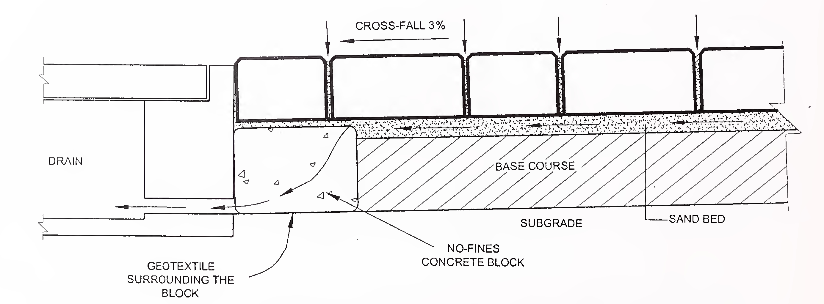
Fig. 9. Surface drainage in a block pavement
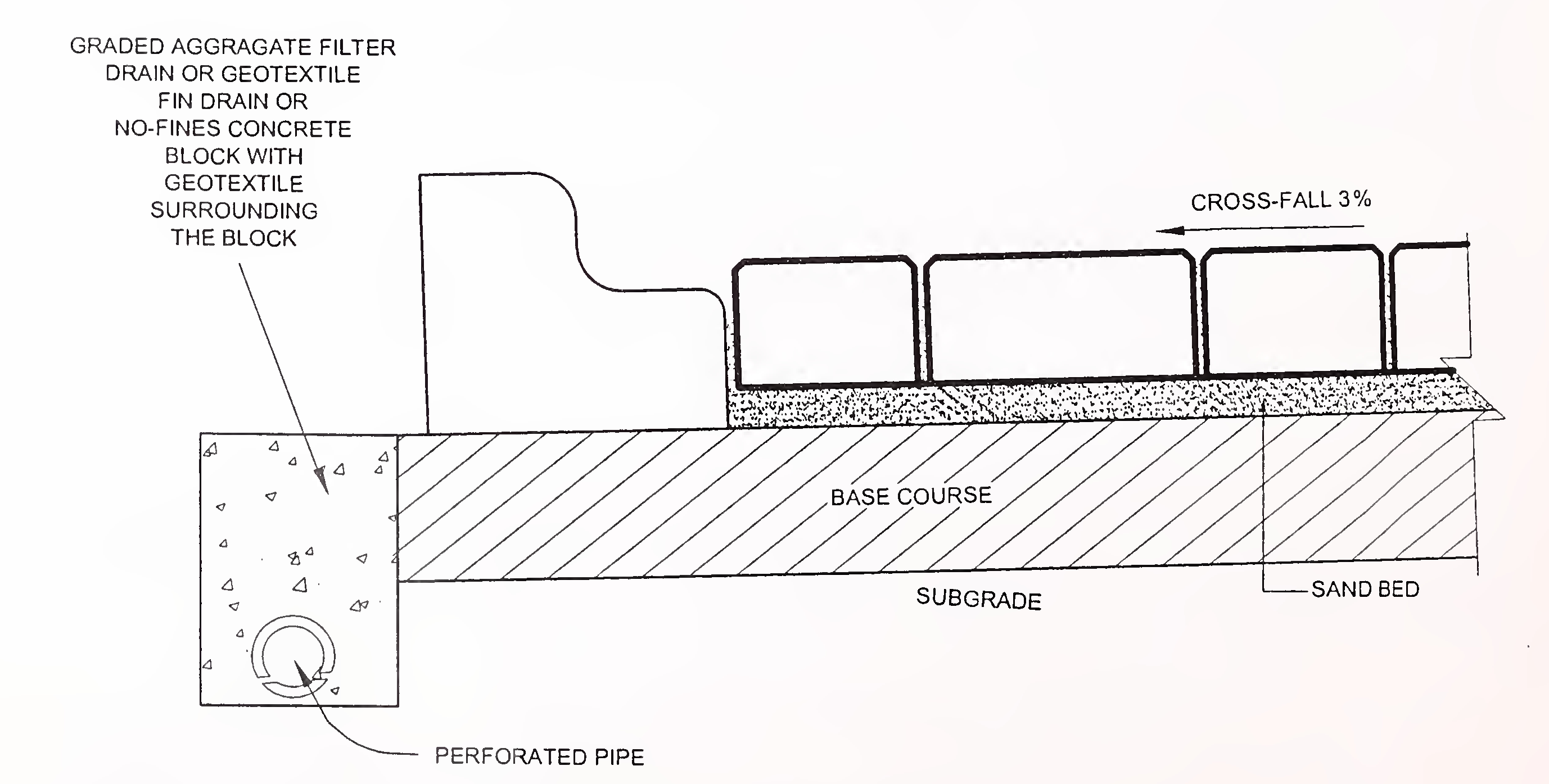
Fig. 10. Surface drainage in a block pavement18
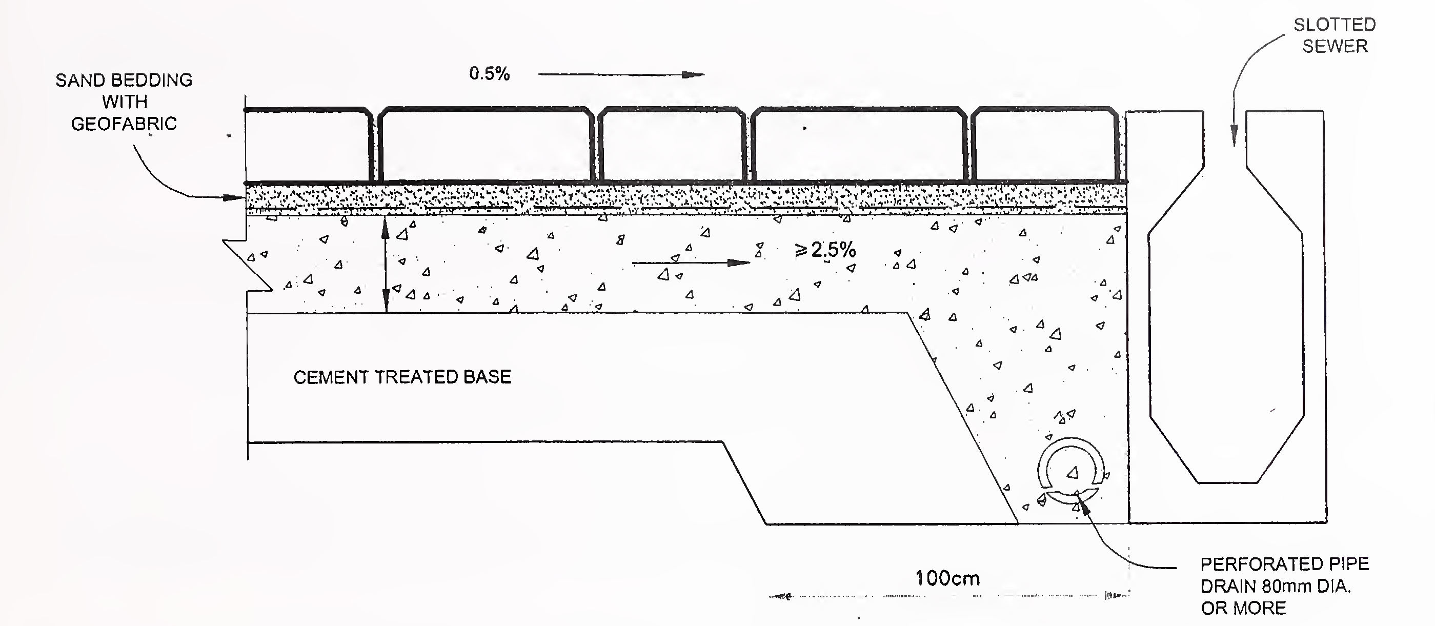
Fig. 11. Heavy trafficked concrete block pavement structure with a base course of no-fines concrete for drainage
A crossfall of 2 per cent slope is generally sufficient to drain the surface run-off but it is desirable to provide 3 per cent crossfall in the case of heavily trafficked roads to avoid formation of water puddles. The block pavement should be at least 5 mm above the manholes, side drains, etc.
The construction of block pavement involves preparation of subgrade, sub-base and base course layers, bedding sand and finally the laying of blocks. The block paving can be done entirely by manual labour. However, for efficient construction work, the work force has to be properly trained for this specialised job. Paving can also be done by mechanical means.
This is the foundation layer on which the block pavement is constructed. Like in conventional pavements the water table should be at a minimum depth of 600 mm below the subgrade. Subgrade should be compacted in layers of 150 or 100 mm thickness as per IRC:36-1970. The prepared subgrade should be graded and trimmed to a tolerance of ± 20 mm of the design levels, and its surface evenness should have a tolerance of within 15 mm under a 3 m straight edge.
Base and sub-base courses are constructed in accordance with standard procedures contained in the relevant IRC Specifications, like, IRC:37-2001, IRC:50-1973, IRC:51-1993, IRC:63-1976,19 IRC: 19-1977. When cement bound base are proposed it may be constructed using rolled lean concrete as per IRC:SP-49. The quality control specified in IRC:SP-11 shall apply. Constructing the layers to proper level and grade is very essential to maintain the level and surface regularity of the block pavement.
The thickness of the sand bed after compaction should be in the range of 20-40 mm, whereas, in the loose form it can be 25 to 50 mm. It is preferable to restrict the compacted thickness to 20-25 mm to reduce the risk of any localized precompaction, which would affect the final block surface level. Bedding sand should not be used to fill-up local depressions on the surface of a base or subbase. The depressions should be repaired in advance before placing sand.
Sand to be used should be uniformly in loose condition and should have a uniform moisture content. Best moisture content is that when sand is neither too wet nor too dry and have a value of 6 to 8 per cent. Requirement of sand for a day's work should be prepared and stored in advance and covered with tarpaulin or polythene sheets.
The processed sand is spread with the help of screed boards to the required thickness. The screed boards are provided with nails at 2-3 m apart which when dragged gives the desired thickness. The length of nail should take into account the surcharge to be provided in the uncompacted thickness. Alternatively, the screed can be dragged on edge strips kept on both sides as guide. Asphalt paver can be employed in large projects. The sand is subsequently compacted with plate vibrators weighing 0.6 tonnes or more. Level checks shall be carried out on a grid pattern to establish that the desired level is achieved. Local correction can be done either by removing or adding extra sand followed by levelling and compacting the layer. There will be some settlement of sand after the blocks are placed and compacted, which must be allowed for, while fixing the level of sand bed.
The effect of undulating surface of base or sub-base on the profile of block pavement is explained in Fig. 12. The blocks will settle after trafficking in such a manner that the surface profile becomes parallel to base/sub-base profile. Sand bed assumes uniform thickness under moving loads.
Blocks can be laid generally by manual labour but mechanical aids like hand-pushed trolleys can expedite the work.
Normally, laying should commence from the edge strip and proceed towards the inner side. When dentated blocks are used, the laying done at two fronts will create problem for matching joints in the middle. Hence, as far as possible, laying should proceed in one direction only, along the entire width of the area to be paved.
While locating the starting line, the following should be considered:
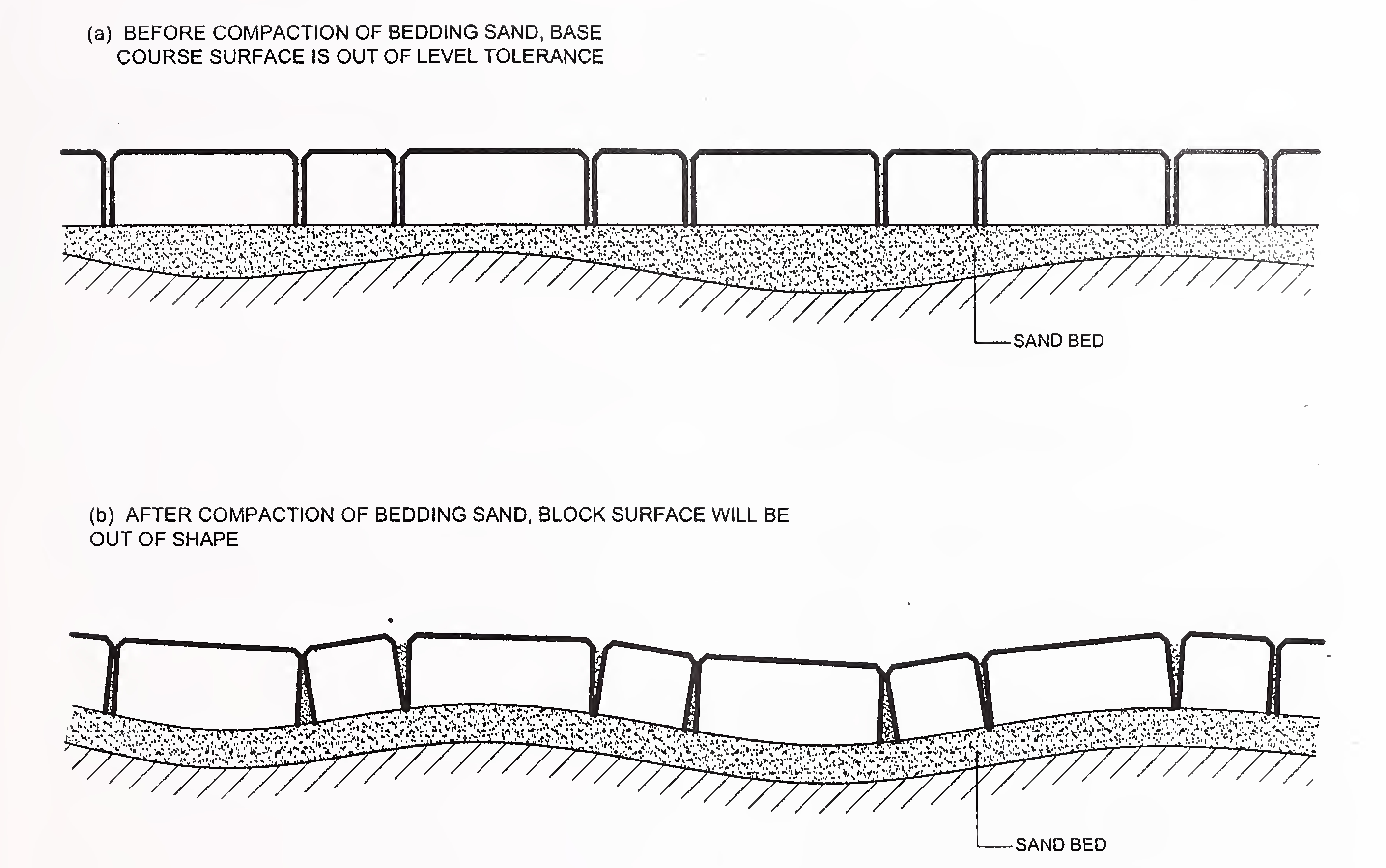
Fig. 12. Effect of base-course surface shape on bedding sand and block surface shape
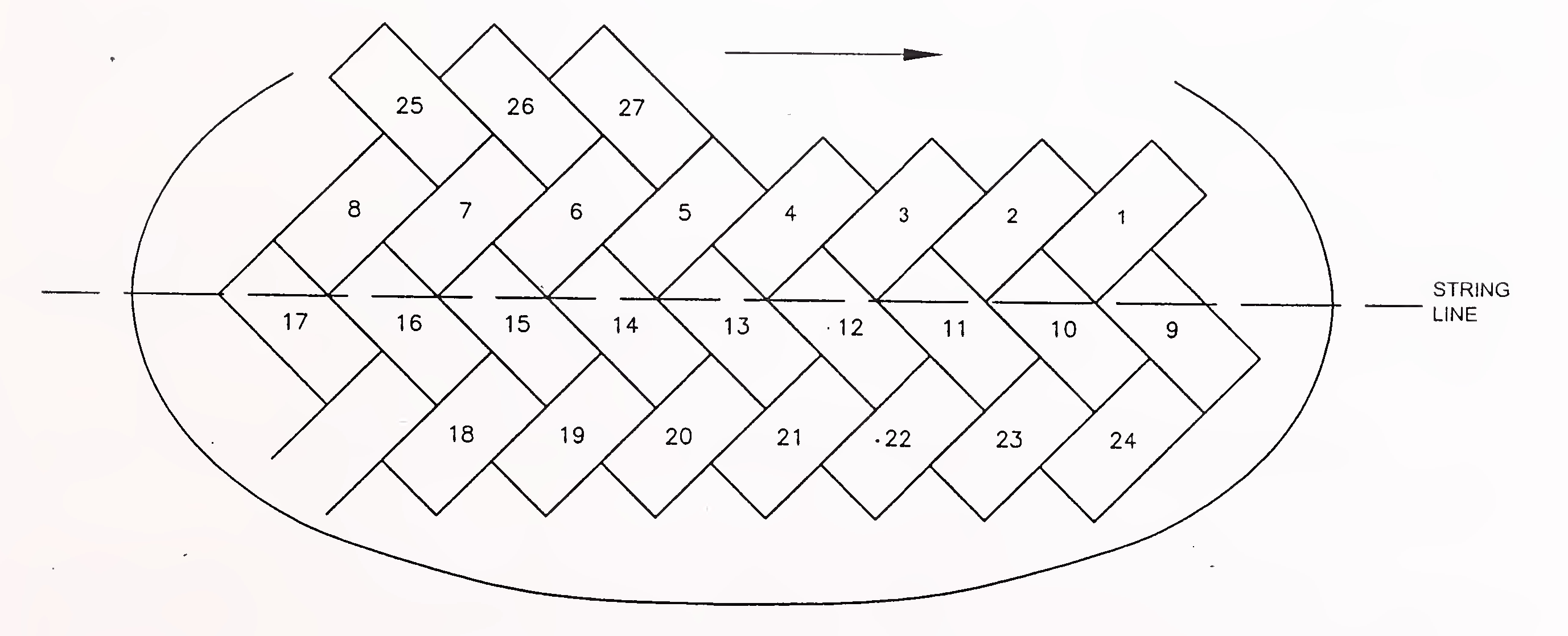
Fig. 13. Starting at irregular shaped edge restraint21
The blocks can be placed to different bonds or patterns depending upon requirement. Some popular bonds commonly adopted for block paving are:
The typical layout of these bonds are given in Fig. 14.
In relation to the starting line, the blocks should be placed at the correct angle to achieve the final orientation as required by the laying pattern. If the edge restraint is straight and suitably oriented, the first row of blocks can abut it. For irregular-shaped and unfavourably oriented edge restraints, a stringline should be established a few rows away to position the first row.
With the help of gauges, the joint width specification (2 to 4 mm) should be checked in the first few square metres, where it should be ensured that the block alignment is correct. The laying patterns and face should be established (Fig. 15) to permit fast and easy laying without the necessity of forcing a block between previously positioned blocks. To start with, full blocks should be used; only subsequently, cutting and in-filling at edges be permitted. Under no circumstances should the blocks be forced or hammered into the bedding sand at this stage of laying. For cutting paving blocks, hydraulic or mechanical block cutters, or power saws are used. Cut units less than 50 mm minimum dimension should not be used, as these are difficult to cut accurately and can be dislodged under traffic. Where space does not permit use of a larger segment, use premixed concrete or a sand-cement mortar instead.
The control over alignment, laying pattern and joint widths can be maintained by the use of chalked string lines, at about 5 m intervals.
In the traditional manual method, the sand is roughly screeded and a skilled worker (called a pavior) levels the sand and then embeds the block using a hammer; he works backwards so as to have a continuous view of the completed pavement in order to obtain a good finish. A pavior, along with an assistant, can lay 50 to 75 m2 of paving per day.
An alternative to the above method, the block layers (generally unskilled labourers) work on the completed surface, moving forward.
For optimum output, it is advantageous to select an easy fitting block shape, with the desirable size being that which can be easily accommodated in the worker's hand; in addition, the blocks should be chamfered for easy handling and their weight should preferably be less than 4 kg.22
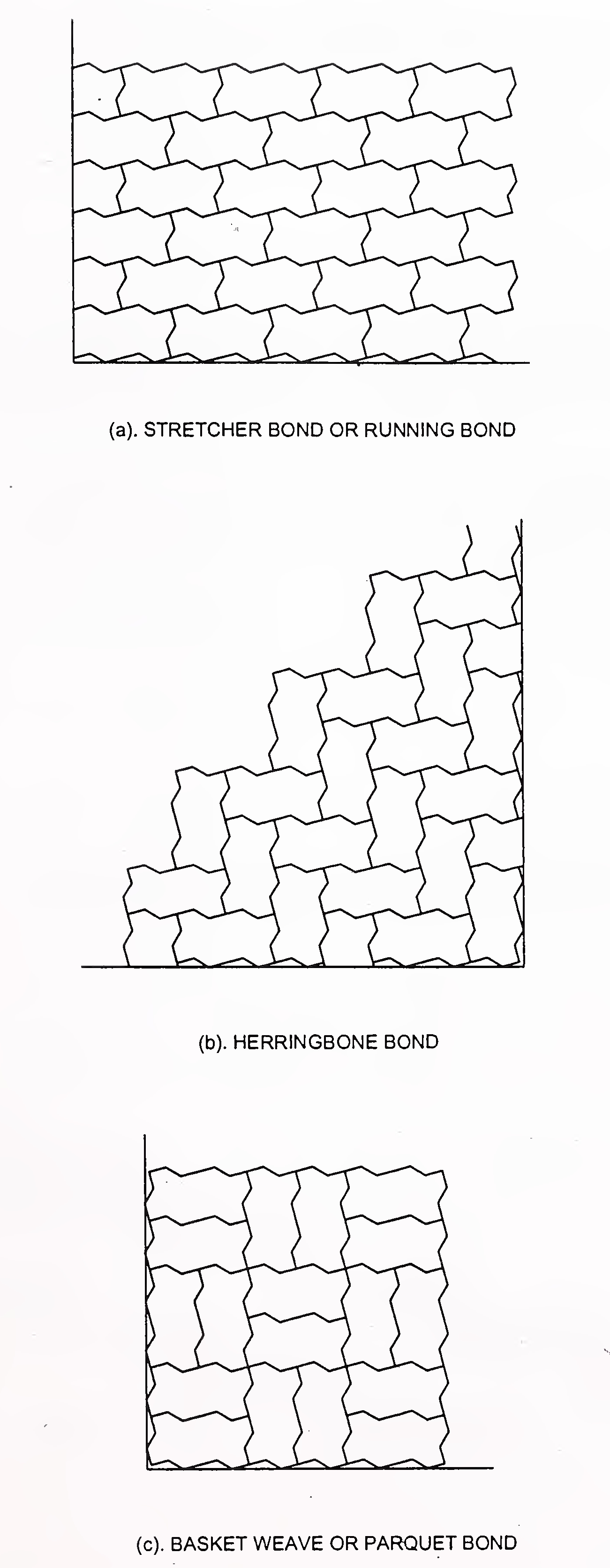
Fig. 14. Typical bond or laying pattern of bond23
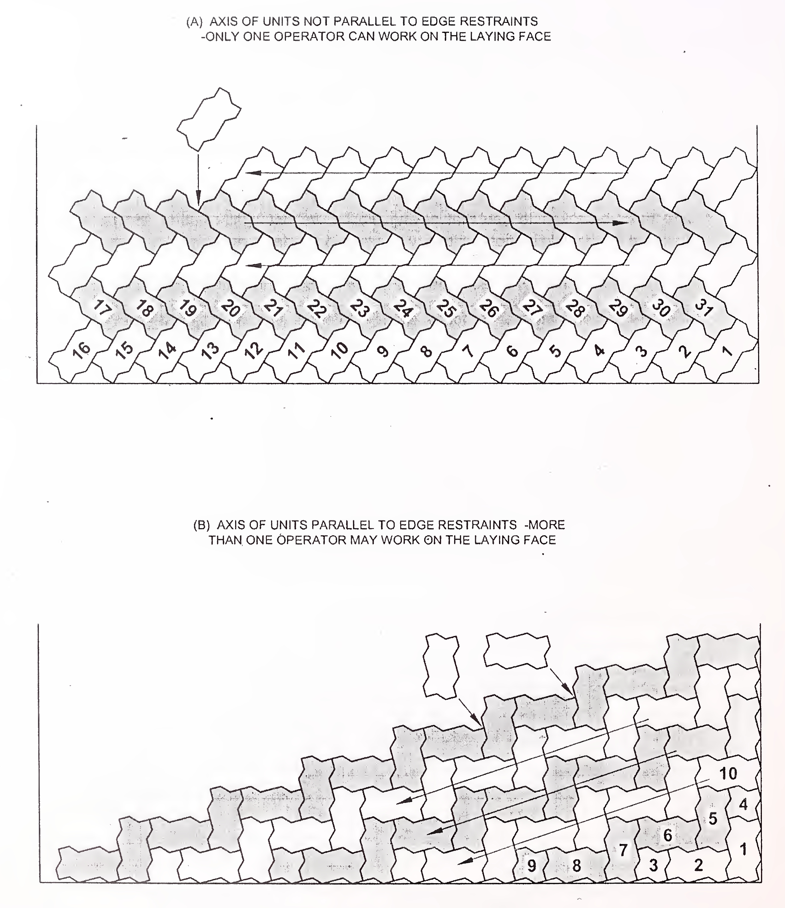
Fig. 15. Establishing laying face for blocks in herringbone bond24
The output of finished pavement varies widely with training of workmen, over a wide range from a low of 20 to a high of 120 m2/man-day; the higher outputs being for industrial hard standings where intrusion like manholes, etc. are minimal. To keep up the speed of work, it is important to maintain an adequate supply of paving blocks to the laying site for manual paving. Ordinarily, hand pushed trolleys are adequate for the purpose, but for large projects employing a number of laying teams, use of powered trolleys is preferable.
Care must be taken to see that paving blocks are not tightly butted against each other, otherwise there could be non-uniformity in the laying patterns and the blocks may spall or even crack. Joint widths of 2 to 4 mm can be maintained if, when laying a paving unit, it is held lightly against the face of an adjacent laid unit and allowed to vertically slide into position.
Since each workman may produce slightly different joint widths, it is desirable to rotate workmen along the workface, and also periodically interchange the personnel laying and transporting blocks.
The average joint width can be measured and checked, by determining statistically the representative values of average length and breadth of blocks at the project site and then obtaining average distance between joints, say 40 blocks apart; or it can be done by measuring joint widths directly, using a calibrated, hardened steel mandrel which is forced into joints at a series of randomly selected locations, to obtain a statistically representative figure.
Mechanised laying requires the use of specialised equipment for transporting and placing clusters of paving blocks. The size of paving block cluster suitable for paving, is usually 0.3 to 0.5 m2 in area for hand-operated equipment; for fully mechanised equipment, the cluster surface area can be upto about 1.2 m2. These clusters are designed to maintain a joint space of about 3 mm between blocks, when clamped together (Fig. 16).
Since the blocks are placed in separate clusters, there exists the possibility of damage if joints between adjacent clusters run uninterrupted throughout the pavement. To overcome this problem, clusters may be arranged so that the joints are periodically staggered both along and across the cluster axis or link blocks are installed by hand across these joints (Fig. 17).
Mechanised laying must be coordinated with the manufacturer, so that the blocks are delivered stacked on pallets in the required pattern; in some cases, spacing ribs may be cast on the sides of blocks to preserve the required joint spacings.
For compaction of the bedding sand and the blocks laid over it, vibratory plate compactors are used over the laid paving units; at least two passes of the vibratory plate compactor are needed. Such vibratory compaction should be continued till the top of each paving block is level with its adjacent blocks. It is not good practice to leave compaction till end of the day, as some blocks may move under construction traffic, resulting in the widening of joints and comer contact of blocks, which may cause spalling or cracking of blocks. There should be minimal delay in compaction after laying of the paving blocks to achieve uniformity of compaction and retention of the pattern of laying; however, compaction should not proceed closer than 1 m from the laying face, except after completion of the pavement.25
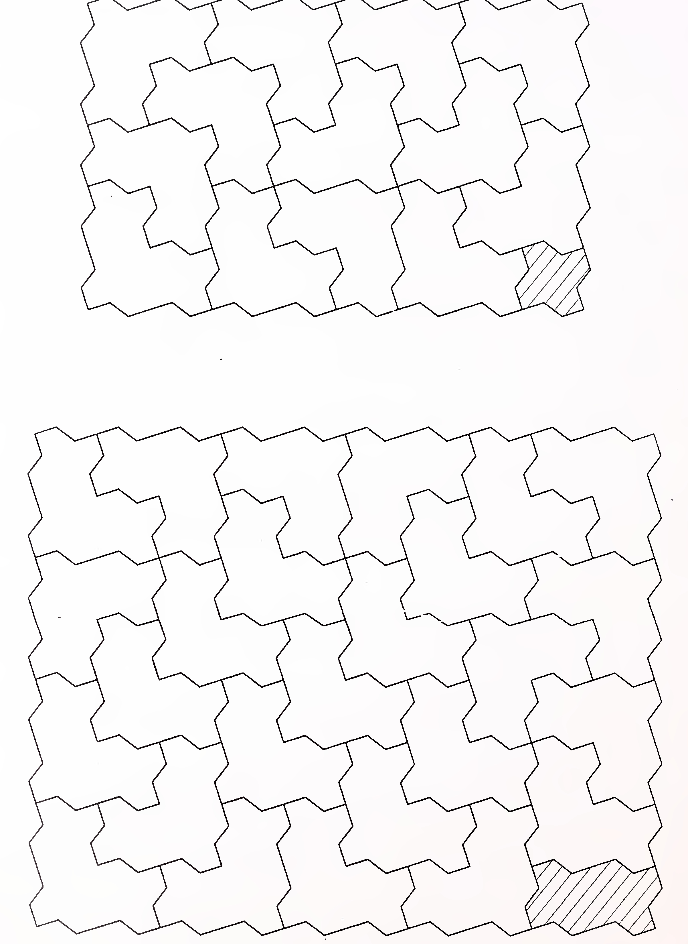
Fig. 16. Typical block cluster in mechanised laying26
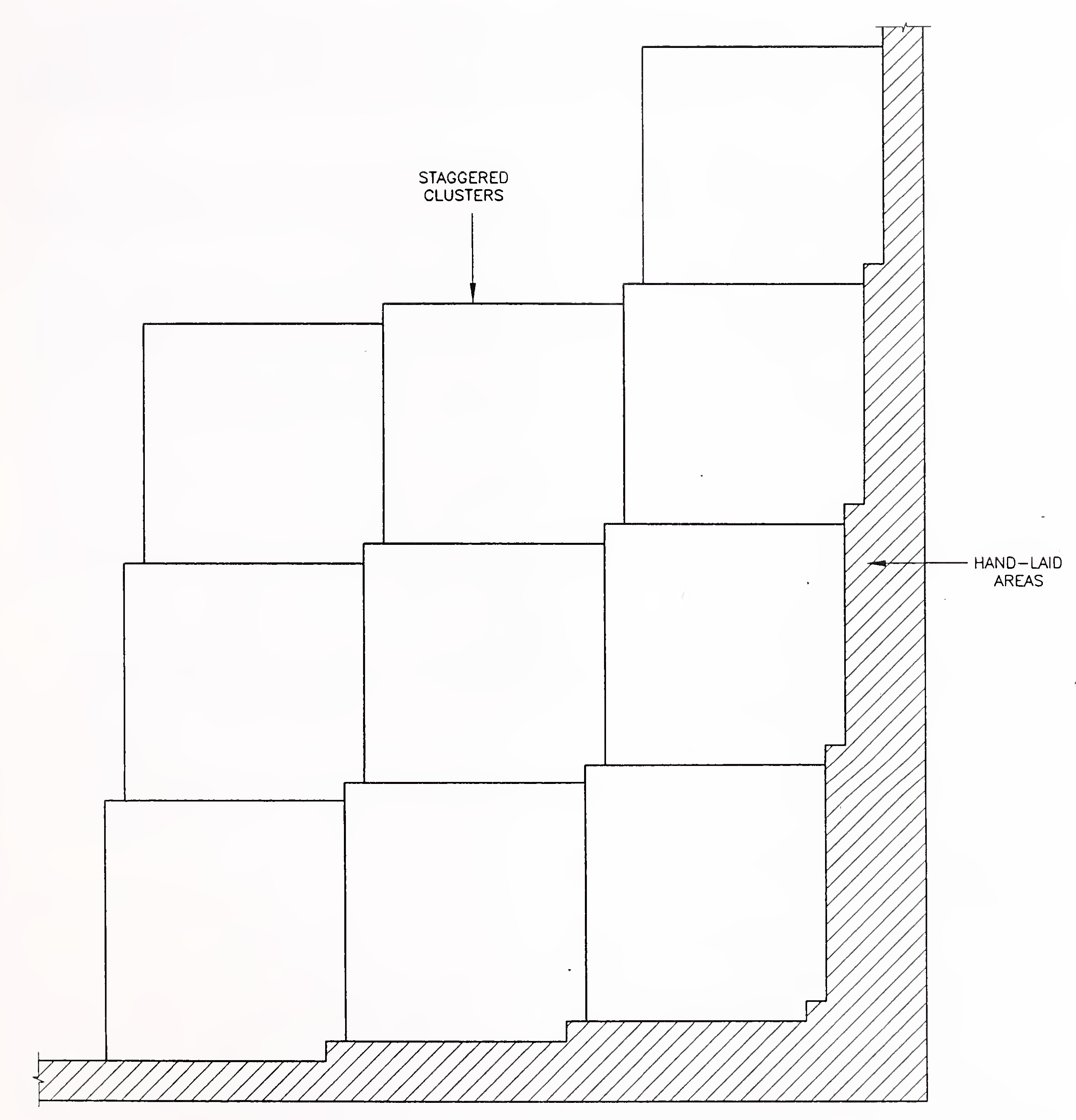
Fig. 17. Staggered installation of block clusters
During vibratory compaction of the laid blocks, some amount of bedding sand will work its way into the joints between them; the extent of sand getting worked up into the joints will depend on the degree of pre-compaction of sand and the force applied by the block compactor. Standard compactors may have a weight of about 90 kg, plate area of about 0.3 m2 and apply a centrifugal force of about 15 kN, while heavy duty compactors may weigh 300-600 kg, have a plate area of about 0.5-0.6 m2 and apply a centrifugal force of 30-65 kN. Where the bedding sand has been pre-compacted and for heavily27
trafficked block pavements, heavy duty compactors should be used. After compaction by vibratory plate compactors, some 2 to 6 passes of a vibratory roller (with rubber coated drums or those of static weight less than 4 tonnes and nominal amplitude of not more than 0.6 mm) will further help in compaction of bedding sand and joint filling.
The importance of complete joint filling cannot be over-emphasised. Unfilled or partially filled joints allow blocks to deflect, leading to loose blocks, possibly spalling the edges and a locally disturbing bedding sand layer, as shown in Fig. 18.
After the compaction of the bedding sand has been completed (and some bedding sand has been forced up in the joints between blocks), the joints should be completely filled with sand meeting the desired specifications, as given in Section 6. The joint filing sand should be stockpiled at suitable locations for convenience. There should be minimum delay in joint filling; the process should in any case, be completed by the end of the day's work.
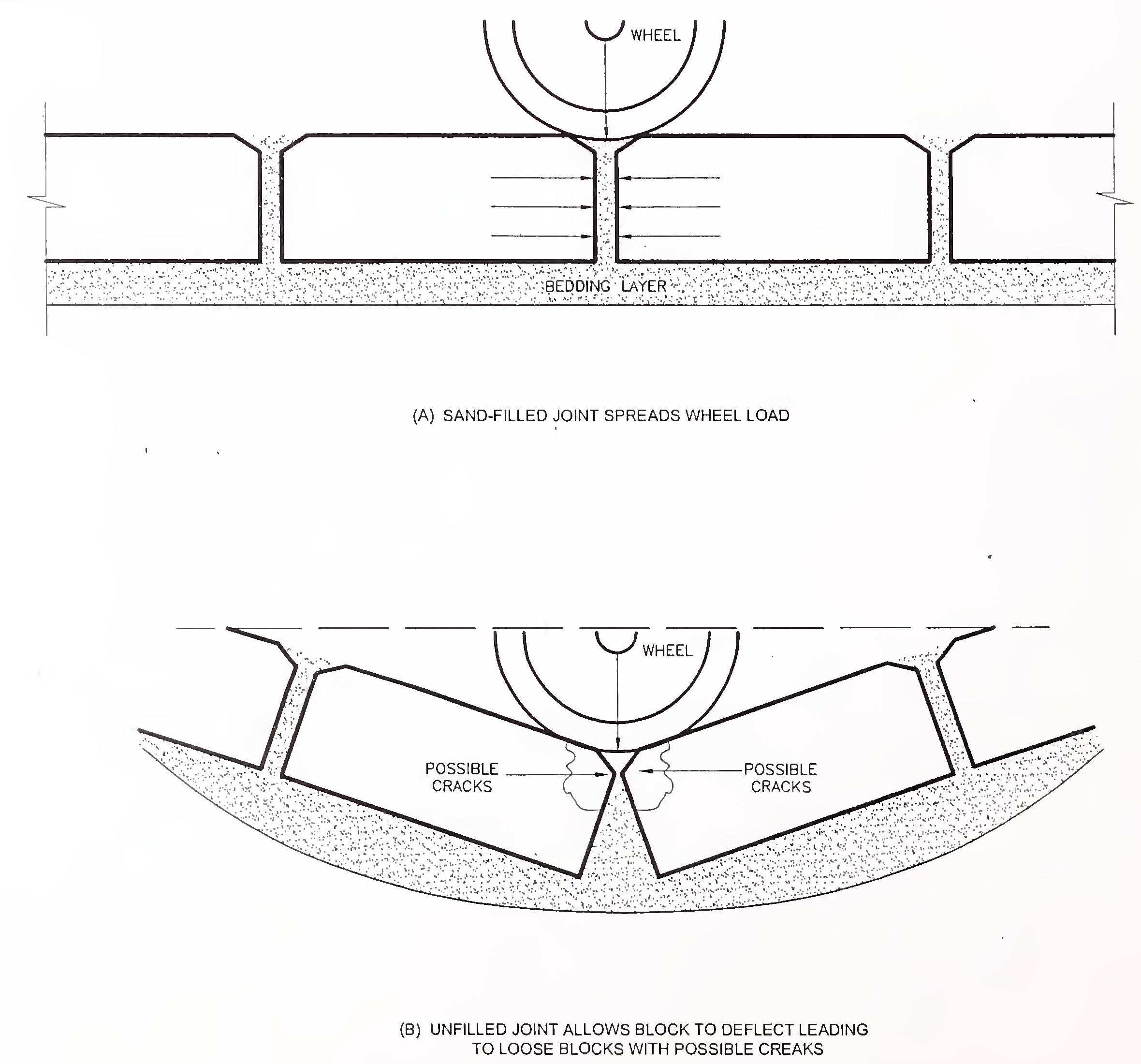
Fig. 18. Need for complete filling of joints28
The operation of joint filling comprises of spreading a thin layer of the joint filling sand on the block surface and working the sand into each joint by brooming. Following this, a far passes of heavy plate compactor are applied to facilitate fine sand to fill the joints. The sand should be broomed or spread over the surface with a small surcharge.
Dry sand and dry blocks are best for the filling of joint, as damp sand tends to stick at the very top of the joints; also, if the blocks is wet and the sand dry, the sand will again stick at the joint top. Hence, if either the blocks or sand are wet, one may get a false impression of the joints being full, but the next rain will reveal that they are actually hollow. If the weather does not allow sand and blocks to be dry, the joint filling sand should be washed in by light sprinkling of water. In this case, several cycles of application of sand, water-sprinkling and plate compaction will be necessary to completely fill the joints.
Until all the joints are completely filled, no traffic should be permitted over the block pavement. In case of lime or cement treated layers in the pavement, it must be ensured that these are given at least 14 and 7 days respectively to cure, before traffic is permitted. The block pavement should be inspected frequently, to ensure that any incompletely filled joints, exposed by traffic and/or weather are promptly filled. Such frequent inspection should be continued till dust and detritus from the roadway tightens the surface of the joints.
While the laying, the surface tolerances, given below may be observed:
| Layer/Item | Tolerance |
|---|---|
| Subgrade | +0, -25 mm of nominated level |
| Select subgrade/Sub-base | +0, -20 mm of nominated level |
| Base Course |
-0, +10 mm of nominated level 10 mm deviation from a 3 m straight edge |
| Plan deviation from any 3 m line from any 10 m line |
10 mm (maximum) 20 mm (maximum) |
| Vertical deviation from 3 m line at kerbs intrusions, channels, edge restraints elsewhere | +3 mm, -0 mm |
| Maximum difference in surface level between adjacent paving units | + 10 mm, -15 mm |
| Deviation of finished surface level from designated level | +10 mm, -15 mm |
| Joint width range | 2 mm to 4 mm |
| Percentage of joints outside range | 10% max. along 10 m line |
| Nominal joint width | 3 mm29 |
Essentially, there are three important aspects in detailing. These are :
It is necessary to cut the paving units to fit the edge restraints. Rectangular blocks of a similar or contrasting colour as an edging have been used to minimise the visual effects of small errors in block cutting. To avoid unsightly and potentially weak construction joints, it is often preferable to change the laying pattern at the curve. For example, as shown in Fig. 19, the curve itself can be installed in herringbone bond and yet the pavement can revert to stretcher bond on the approaches.
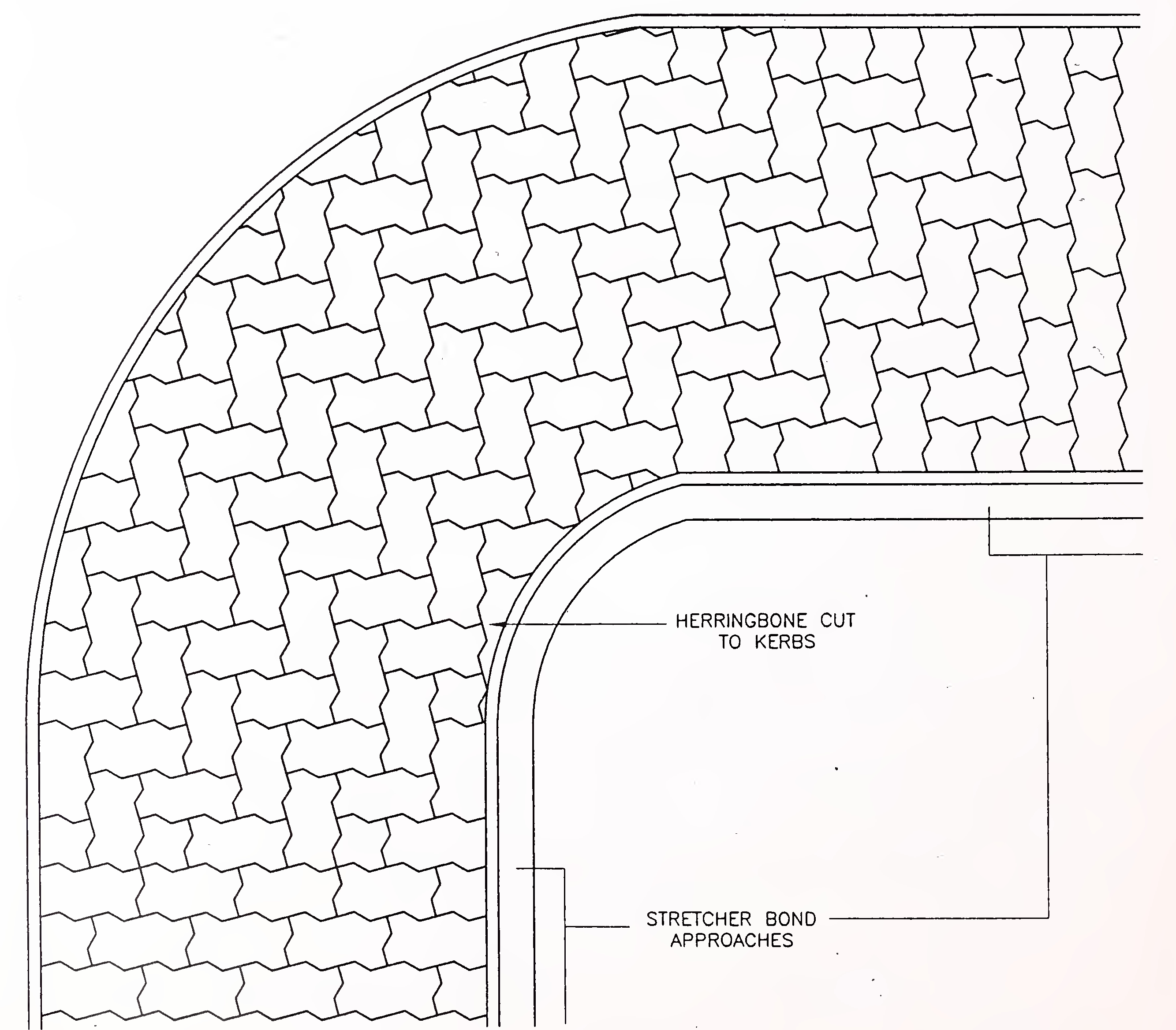
Fig. 19. Curve in herringbone bond and approaches in stretcher bond30
On some pavements, like in city streets, there could be several intrusions, like, manholes, drainage gulleys, etc. where mating these intrusions with the pavement is desirable. Fig. 20 shows how this should be done around a manhole.
Around intrusions, it is good practice to lay along both sides of the intrusion simultaneously so that closure is made away from the starting workface, rather than carrying the pavement around the intrusion to return to the original laying face (Fig. 20) to avoid accumulation of closing error.
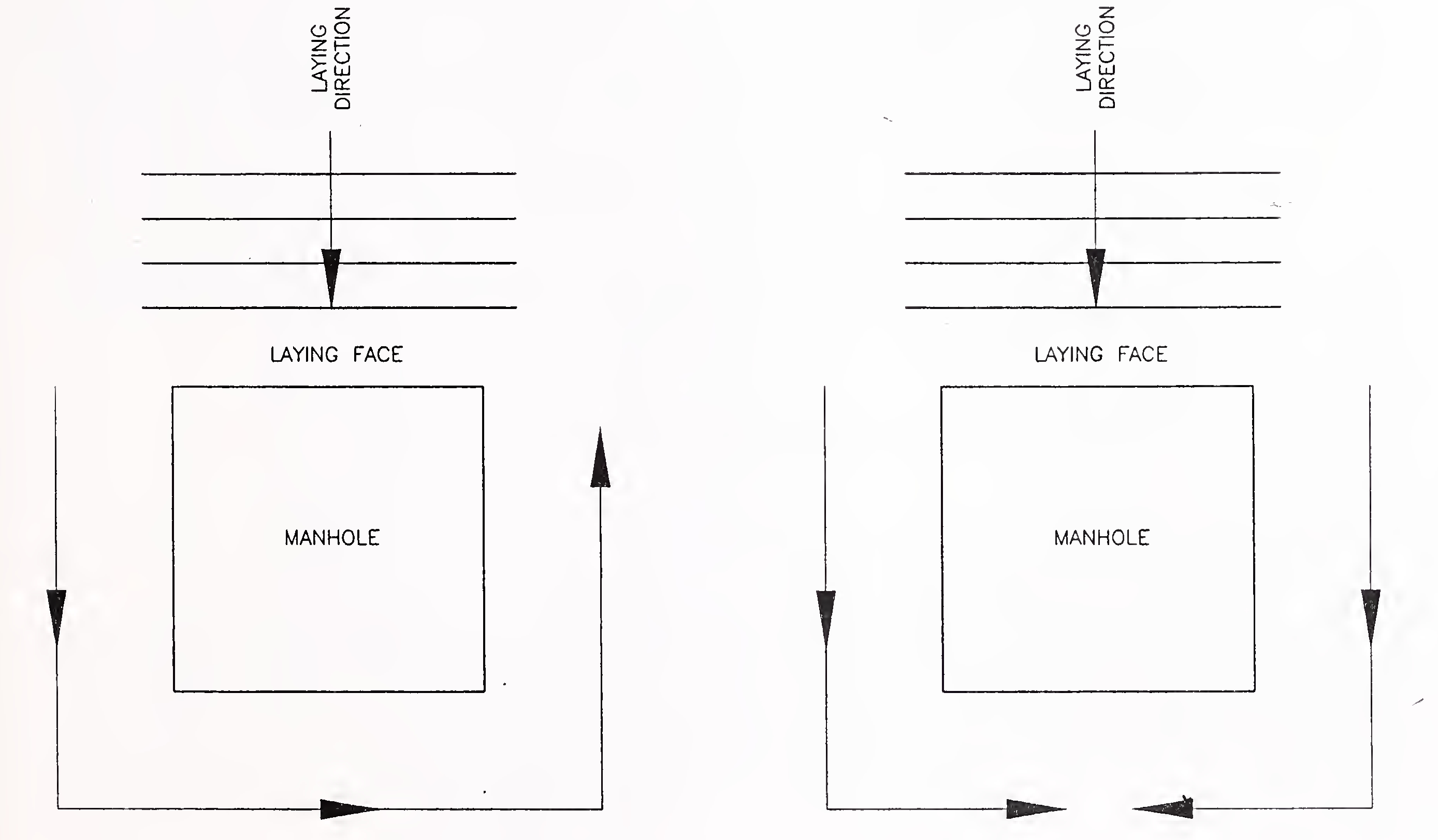
Fig. 20. Laying block paving around a manhole
Changes in alignment of a road pavement can some times be achieved by the use of special blocks. However, it is generally easier to choose a block that can be installed in herringbone bond and simply cut the blocks to fit the edge restraints. Where aesthetic requirements or shape of the paving unit dictate the use of stretcher bond, then only a 90° shape change in alignment can be achieved without cutting the blocks (Fig. 21). At intersections, if a herringbone bond laying pattern is adopted, the paving can proceed without the need for construction joints (Fig. 22). An alternative to this is to install a shoulder (support) course of rectangular paving units between the main roadway and the side streets; this permits different laying patterns to be used in the two roadways.
Annexure-1 gives the specifications for laying. The BIS Specifications for Precast Concrete Blocks for Paving (under publication) may be followed for the manufacture and testing of blocks.31
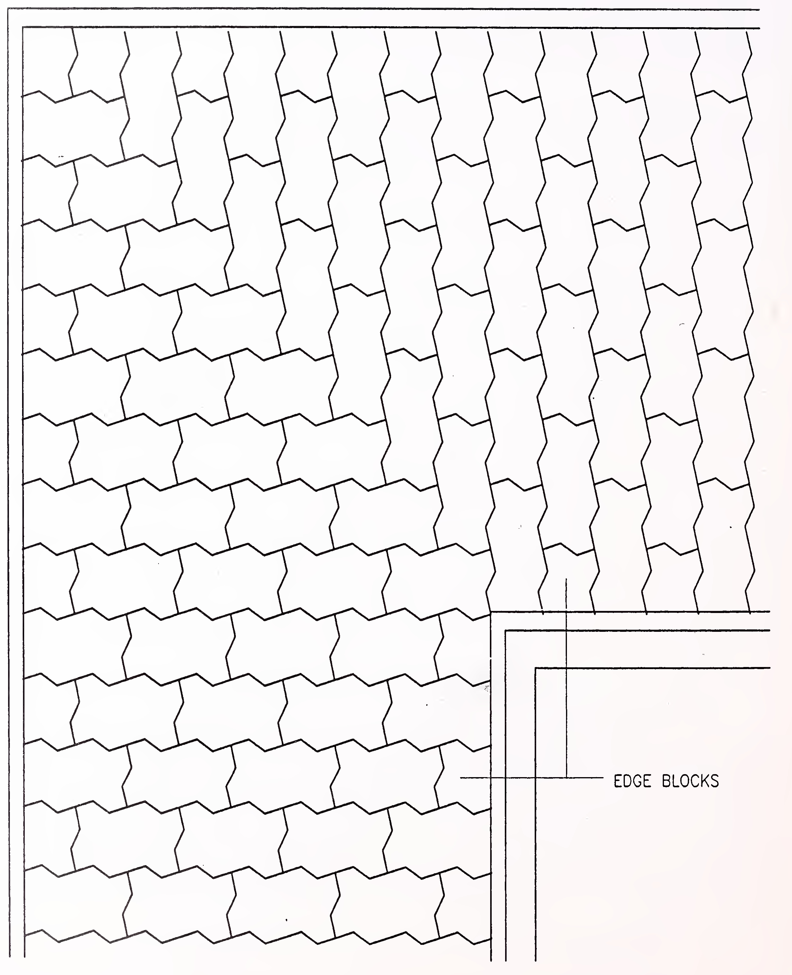
Fig. 21. 90° change in alignment using stretcher bond32
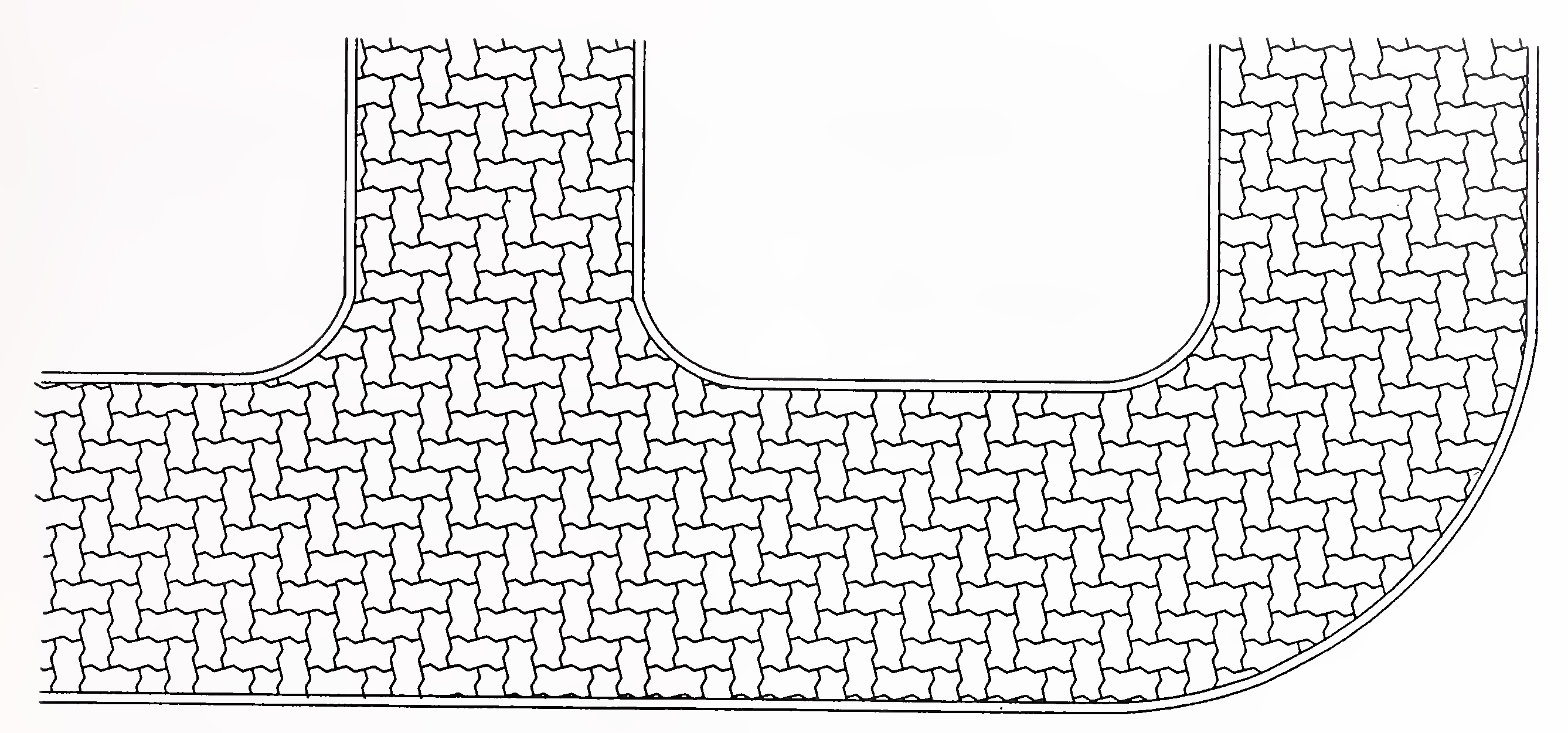
Fig. 22. Adaptation of herringbone bond to changes in alignment
Like any other road work, block pavement also should be maintained to give long service. The maintenance requirement of block pavement is minimal. The block pavement requires initial maintenance soon after its laying, say after a week or two for checking sand in the joints. Subsequently, the maintenance is in the form of replacing any damaged block/blocks or raising the settled section, if any. Repair especially after laying a cable duct is much simpler in the case of block pavements. The cut area can be reinstated without any blemish.
After about a week of laying the blocks there is a need to inspect the surface to check for any loss of sand at joints. Wherever sand level has dropped down it should be reinstated. This type of inspection should continue for two to three months till the sand level is stabilized and topping up is no more required. With time the joints receive fine dust and detritus thus making them waterproof. During rains these joints may allow weeds to grow but these normally should get eliminated with the traffic. In case it does not get eliminated these may have to be controlled by spraying herbicide or by manual removal. Annual inspection, however, will be required.
For the purpose of reinstating damaged blocks it is necessary to stockpile a small percentage of blocks from the lots used in the construction. The size and colour of the blocks may be difficult to obtain at a later date matching with the original blocks. For important projects, it is normal to stockpil blocks from 1 per cent to 3 per cent initial supply for subsequent use.33
As part of preventive maintenance, blocks can be sealed using compounds, like, silicone, acrylics and silica flourides for enhancing the colour, reducing absorptive nature of the blocks and for improving surface toughness. These coating have life of 1 to 3 years and hence they have to be repeated as per the requirement. The most durable of these chemicals is solvent-borne acrylics which are abrasion resistant and also minimize chemical effects of spillage even at 60°C.
Cleaning of block pavement can be done by mechanical brooms, compressors or even by manual means. For removing certain stains, chemicals, like, oxalic, acetic and phosphoric acids etc. are used. Sometimes it may be expedient to replace the blocks where stains have penetrated to a greater depth.34
Annexure
The Finished surface of the concrete base shall match the design profile of the concrete blocks within ±10 mm.
Compaction shall be done with vibratory roller. In restricted areas where normal rollers cannot operate, hand-held or plate vibrators should be employed.
The bedding sand layer shall be from either a single source or blended to achieve the following grading.
| IS Sieve Size | Per cent Passing |
| 9.52 mm | 100 |
| 4.75 mm | 95-100 |
| 2.36 mm | 80-100 |
| 1.18 mm | 50-95 |
| 600 micron | 25-60 |
| 300 micron | 10-30 |
| 150 micron | 0-15 |
| 75 micron | 0-10 |
Single sized, gap-graded sands or those containing an excessive amount of fines will not be used. The sand particles should preferably be angular type.
The joint-filling sand should pass a 2.35 mm sieve and be well graded. The following grading is recommended:
| Sieve Size | Per cent Passing |
| 2.36 mm | 100 |
| 1.18 mm | 90-100 |
| 600 micron | 60-90 |
| 300 micron | 30-60 |
| 150 micron | 15-30 |
| 75 micron | 0-10 |
The use of cement in the joint-filling sand is not recommended as a general practice as the cemented sand is likely to crack into segments which are easily dislodged.
Average thickness of this laying course shall be 20 to 40 mm.
The sand should be slightly moist, and the moisture content shall be about 4 per cent by weight.35
It should contain not more than 3 per cent by weight of clay and silt and the materials shall be free from deleterious salts or contaminates.
The finished surface of the bedding layer shall match exactly the design profile as indicated on the drawings.
Before placing the bedding layers, the surface of concrete should be cleared by sweeping.
Walking or driving on the finished surface of the bedding layer shall not be permitted.
Laying of the blocks shall be done, precisely at the indicated level and profile and in a way that a good surface draining to the gulley chambers is assured.
Around gulley chambers and inspection pits the pavement shall have a level of 5 mm higher than the above mentioned elements.
The blocks shall be laid to the pattern directed by the Engineer or the pattern recommended by the designer. The blocks shall be laid as tight as possible to each other. The maximum joint width shall be limited to 4 mm.
Laying of broken blocks is not allowed except along connections or edges. The maximum length of a purpose broken block is 100 mm. Breaking of the blocks shall be done with a “block splitter” or a mechanical saw.
Fine angular sand as per specification shall be brushed into the joints, and thereafter compaction shall be done with a vibrating plate compactor on a clean surface. After compaction, again fine angular sand shall be brushed into the joints.
Surface tolerance for finished surface shall be ±10 mm from the design level.
The surface tolerance for base course shall be in the range of 0 to +10 mm from nominated level and 10 mm deviation from a 3 m straight edge.
The surface tolerance for sub-base shall be within 0 to -20 mm of nominated level.