This library of books, audio, video, and other materials from and about India is curated and maintained by Public Resource. The purpose of this library is to assist the students and the lifelong learners of India in their pursuit of an education so that they may better their status and their opportunities and to secure for themselves and for others justice, social, economic and political.
This item has been posted for non-commercial purposes and facilitates fair dealing usage of academic and research materials for private use including research, for criticism and review of the work or of other works and reproduction by teachers and students in the course of instruction. Many of these materials are either unavailable or inaccessible in libraries in India, especially in some of the poorer states and this collection seeks to fill a major gap that exists in access to knowledge.
For other collections we curate and more information, please visit the Bharat Ek Khoj page. Jai Gyan!
IRC:SP:58-1999
Indian Roads Congress
Special Publication 58
Published by
THE INDIAN ROADS CONGRESS
Copies can be had from
The Secretary, Indian Roads Congress
Jamnagar House, Shahjahan Road,
New Delhi-110011
NEW DELHI 2001
Price Rs. 120.00
(plus packing and postage)
PERSONNEL OF HIGHWAYS SPECIFICATIONS AND STANDARDS COMMITTEE
(As on 22.8.2000)
| 1. | Prafulla Kumar (Convenor) |
Director General (Road Dev.) & Addl. Secretary to the Govt. of India, Ministry of Road Transport & Highways, Transport Bhavan, New Delhi-110001 |
| 2. | S.C. Sharma (Co-Convenor) |
Chief Engineer, Ministry of Road Transport & Highways, Transport Bhavan, New Delhi-110001 |
| 3. | The Chief Engineer (R) S&R (Member-Secretary) |
(C.C. Bhattacharya), Ministry of Road Transport & Highways, Transport Bhavan, New Delhi-110001 |
| Members | ||
| 4. | M.K. Agarwal | Engineer-in-Chief (Retd.), House No. 40, Sector 16, Panchkula-134113 |
| 5. | P. Balakrishnan | Chief Engineer (Retd.), Highways & Rural Works Department., No.7, Ashoka Avenue, Kodambakkam, Chennai-600024 |
| 6. | Dr. R.K. Bhandari | Head,International S&T Affairs Directorate, Council of Scientific & Industrial Research, Anusandhan Bhavan, 2, Rafi Marg, New Delhi-110001 |
| 7. | P.R. Dutta | Chief Engineer (Mech.), Ministry of Road, Transport & Highways, Transport Bhavan, New Delhi-110001 |
| 8. | D.P. Gupta | DG(RD) (Retd.), E-44, Greater Kailash Part-I Enclave, New Delhi-110048 |
| 9. | Ram Babu Gupta | Chief Engineer-cum-Officer on Spl. Duty with Public Works Minister, 9 Hathori Market, Ajmer Road, Jaipur-302001i |
| 10. | Dr. L.R. Kadiyali | Chief Executive, L.R. Kadiyali & Associates, C-6/7, Safdarjung Dev. Area, Opp. IIT Main Gate, New Delhi-110016 |
| 11. | J.B. Mathur | Chief Engineer, Ministry of Road Transport & Highways, Transport Bhavan, New Delhi-110001 |
| 12. | H.L. Meena | Chief Engineer-cum-Addl. Secy. to the Govt. of Rajasthan, P.W.D., Jacob Road, Jaipur-302006 |
| 13. | S.S. Momin | Chief Engineer, Maharashtra State Road Dev. Corpn. Ltd., Nappean Sea Road, Mumbai-400036 |
| 14. | Jagdish Panda | Engineer-in-Chief-cum-Secy. to the Govt. of Orissa, Works Department, Bhubaneswar-751001 |
| 15. | S.I. Patel | Chief General Manager, National Highways Authority of India, 1, Eastern Avenue, Maharani Bagh, New Delhi-110065 |
| 16. | M.V. Patil | Secretary (Roads), Maharashtra P.W.D., Mantralaya, Mumbai-400032 |
| 17. | K.B. Rajoria | Engineer-in-Chief, Delhi P.W.D. (Retd.), C-II/32, Moti Bagh, New Delhi-110031 |
| 18. | Dr. Gopal Ranjan | Director, College of Engg. Roorkee, 27th KM Roorkee-Hardwar Road, Vardhman Puram, Roorkee-247667 |
| 19. | S.S. Rathore | Spl. Secretary & Chief Engineer (SP), R&B, Block No. 14/1, Sardar Bhavan, Sachivalaya, Gandhinagar-382010 |
| 20. | K.K. Sarin | DG(RD) & AS, MOST (Retd.), S-108, Panchsheel Park, New Delhi-110017 |
| 21. | Dr. S.M. Sarin | Dy. Director, CRRI (Retd.), 2295, Hudson Lines, G.T.B. Nagar, Delhi-110009ii |
| 22. | H.R. Sharma | Associate Director (Highways), Intercontinental Consultants & Technocrats Pvt. Ltd., A-ll, Green Park, New Delhi-110016 |
| 23. | Dr. C.K. Singh | Engineer-in-Chief-cum-Addl. Commissioner-cum-Spl. Secy., Road Constn. Department, Ranchi (Jharkhand) |
| 24. | Nirmal Jit Singh | Chief Engineer (Plg.), Ministry of Road Transport & Highways, Transport Bhavan, New Delhi-110001 |
| 25. | Prabhash Singh | Chief Enginer, Zone-Ill, Delhi P.W.D., MSO Building, I.P. Estate, New Delhi-110002 |
| 26. | Dr. Geetam Tiwari | Transortation Res. & Injury Prevention Programme, MS 808 Main Building, Indian Institute of Technology, New Delhi-110016 |
| 27. | K.B. Uppal | Director, AIMIL Ltd., Naimex House, A-8, Mohan Co-operative Indl. Estate, Mathura Road, New Delhi-110044 |
| 28. | V.C. Verma | Executive Director, Oriental Structural Engrs.Ltd., 21, Commercial Complex, Malcha Marg, Diplomatic Enclave, New Delhi-110021 |
| 29. | P.D. Wani | Member, Maharashtra Public Service Commission, 3rd Floor, Bank of India Building, M.G. Road, Mumbai-400001 |
| 30. | The Engineer-in-Chief | (S.S. Juneja) H.P. Public Works Department, U.S. Club, Shimla-171001 |
| 31. | The Chief Engineer (B) S&R | (V. Velayutham), Ministry of Road Transport & Highways, Transport Bhavan, New Delhi-110001 |
| 32. | The Principal Secy. to the Govt. of Gujarat | (H.P. Jamdar), R&B Department, Sardar Bhavan, Block No. 14, Sachivalaya, Gandhinagar-382010iii |
| 33. | The Engineer-in-Chief | (V. Murahari Reddy), R&B Department, A&E AP, Errum Manzil, Hyderabad-500082 |
| 34. | The Engineer-in-Chief | (R.R. Sheoran), Haryana Public Works Deptt., B&R, Sector 19-B, Chandigarh-160019 |
| 35. | The Member | (R.L. Koul), National Highways Authority of India, 1, Eastern Avenue, Maharani Bagh, New Delhi-110065 |
| 36. | The Director & Head | (S.K. Jain), Civil Engg. Department, Bureau of Indian Standards, Manak Bhavan, 9, Bahadur Shah Zafar Marg, New Delhi-110002 |
| 37. | B.L. Tikoo | Addl. Director General, Dte. General Border Roads, Seema Sadak Bhavan, Ring Road, Delhi Cantt., New Delhi-110010 |
| 38. | The Director (R&D) | (Dr. A.K. Bhatnagar), Indian Oil Corporation Ltd., R&D Centre, Sector 13, Faridabad-121007 |
| 39. | The Director, HRS | (V. Elango) , Highways Research Station, P.B. No.2371, 76, Sardar Patel Road, Chennai-600025 |
| 40. | The Director General of Works | Engineer-in-Chief s Branch, AHQ, Kashmir House, Rajaji Marg, New Delhi-110011 |
| Ex-Officio Members | ||
| 41. |
President, Indian Roads Congress | M.V. Patil Secretary (Roads), Maharashtra P.W.D., Mantralaya, Mumbai-400032 |
| 42. |
Hon. Treasurer, Indian Roads Congress |
Prafulla Kumar Director General (Road Dev.) & Addl. Secretary to the Govt. of India, Ministry of Road Transport & Highways, New Delhiiv |
| 43. |
Secretary, Indian Roads Congress |
G. Sharan Chief Engineer, Ministry of Road Transport & Highways, New Delhi |
| Corresponding Members | ||
| 1. | Prof. C.E.G. Justo | Emeritus Fellow, 334, 25th Cross, 14th Main, Banashankari 2nd Stage, Bangalore-560070 |
| 2. | I.J. Mamtani | Chief Engineer, MOST (Retd.), G-58, Lajpat Nagar-III, New Delhi-110024 |
| 3. | N.V. Merani | Principal Secretary, Maharashtra PWD (Retd.), A-47/1344, Adarsh Nagar, Worli, Mumbai-400025 |
| 4. | Prof N. Ranganathan | Head of Deptt. of Transportation Plg., SPA (Retd.), Consultant, 458/C/SFS, Sheikh Sarai I, New Delhi-110017 |
| 5. | Prof C.G. Swaminathan | ‘Badri’ , 6, Thiruvengandam Street, R.A. Puram, Chennai-600028v |
* ADG(R) being not in position, the meeting was presided by Shri Prafulla Kumar, DG(RD) & Addl. Secretary to the Govt. of India, MORT&II
The Geotechnical Engineering Committee in its first meeting held on 15.7.97 requested CRRI (Shri A.V.S.R. Murty) to prepare draft for Use of Fly Ash in Road Embankments. The draft prepared by Shri A.V.S.R. Murty was discussed by the Committee in its meeting held on 15.5.98. During the meeting, few corrections/modifications suggested by the members were carried out. The Committee in its meeting held on 22.10.99 formed a Sub-group consisting the following to look into the draft. The Sub-group held its meeting on 26.11.99 and approved the draft for placing before the Geotechnical Engineering Committee (H-3):
| 1. | Sanjay Gupta | Member-Secretary/Coordinator |
| 2. | K.N. Agarwal | Member |
| 3. | A.P.S. Sethi | Member |
| 4. | S.K. Soni | Member |
| 5. | Deep Chandra | Member |
| 6. | U.K. GuruVittal | Member |
| 7. | A.K. Mathur | Member |
| 8. | Arun Kumar Sharma | Director (T), IRC |
The Geotechnical Engineering Committee (Personnel given below) in its meeting held on 6.12.99 approved the draft.
| Dr. Gopal Ranjan | Convenor |
| Sanjay Gupta | Member-Secretary |
| Members | |
| Dr. U.N. Sinha | Dr. A. Vardarajan |
| A.V. Sinha | S.I. Patel |
| Lt.Col. V.K. Ganju | A.K. Chakrabarti1 |
| Ashok Wasan | S.B. Basu |
| Sukomal Chakrabarti | Vinod Kumar |
| I.C.Goel | P.J. Rao |
| M.R. Dighe | CE(R) S&R, MORT&H (C.C. Bhattacharya) |
| Dr. V.M. Sharma CE, Hill Zone, Lucknow |
|
| Ex-Officio Members | |
| President,IRC (K.B. Rajoria) |
DG(RD) & Addl. Secretary, MORT&H (Prafulla Kumar) |
| Secretary, IRC (S.C. Sharma) |
|
| Corresponding Members | |
| Dr. M.R. Madhav | K.B. Rajoria |
| Dr. B.V.S. Viswanathan | |
The draft was discussed by the members of the Highways Specifications and Standards (HSS) Committee in its meeting held on 21.12.99. During the meeting, it was decided that the details of some recently completed projects should be removed and then the document be recirculated to this Committee. The draft was discussed in newly constituted HSS Committee members and was discussed during the meeting held on 22.8.2000. After detailed discussions, the draft was approved by the Committee and authorised the Convenor, Geotechnical Engineering Committee to modify the draft in light of the comments of members. The modified draft submitted by Convenor, Geotechnical Engineering Committee was approved by Convenor, HSS Committee and later by the Executive Committee in its meeting held on the 30thAugust, 2000. The draft was approved by Council in its 160th Meeting held at Kolkata on 4.11.2000.
The contributions from Central Road Research Institute and Fly Ash Mission, Department of Science and Technology, Govt. of India, are acknowledg2
Due to industrialisation and rapid economic growth, demand for electricity has risen tremendously. To meet this demand, a number of coal based thermal power plants have been set up. At present, in India thermal power plants produce about 90 million tonnes of fly ash per annum, and hardly 13 per cent of it is utilised.
When pulverised coal is burnt in the furnace of the power stations, about 80 per cent of the ash produced is very fine in nature. This part gets carried along with flue gases and is collected by using either electro-static precipitator or cyclone precipitator. This is called fly ash. The remaining ash sinters and falls down at the bottom of the furnance. This is known as bottom ash. Fly ash may be disposed in dry form (in ash mounds or through water slurry in a pond. When fly ash and bottom ash are mixed and disposed in the form of water slurry to ash ponds, it is called pond ash. For the purpose of embankment construction either pond ash, bottom ash or mound ash can be used. Fly ash being a very fine material is not recommended for embankment construction. However, it may be noted that the term "fly ash" is commonly used as a generic term to denote any type of coal ash. For the purpose of these guidelines the term fly ash would denote Pond Ash/Bottom Ash/Mound Ash, which are to be used for embankment construction.
Fly ash is causing environmental pollution, creating health hazards and requires large areas of precious land for disposal. Due to increasing concern for environmental protection and growing awareness of the ill effects of pollution, disposal of ash generated at thermal power plants has become an urgent and challenging task. Fly ash can be utilised in many ways as shown through extensive R&D efforts as well as field demonstration. But bulk utilisation is possible in the field of civil engineering applications especially construction of road embankments. Typically, in developed urban and industrial areas, natural borrow sources are scarce, expensive or inaccessible. The environmental degradation caused due to the use of topsoil for embankment construction is very high. Moreover, many power plants are situated in urban areas, and therefore, fly ash can provide an environmentally preferable alternative to natural borrow soil.3
The properties of fly ash vary depending upon type of coal, its pulverisation and combustion techniques, their collection and disposal systems, etc. Ash collected from the same ash pond may exhibit different physical and engineering properties depending on point of collection, depth, etc. Obviously, ash from two different thermal power plants can be expected to have different properties. These factors can be easily taken care during characterisation, design and quality control operations during construction. In spite of variations in its properties, fly ash possesses several desirable characteristics, such as, lightweight, ease of compaction, faster rate of consolidation, etc. Also, spreading and compaction of fly ash can be started much earlier in comparison to soil after a rainfall. Fly ash would be a preferred material for construction of embankments over weak subsoil.
These guidelines provide salient details regarding design and construction of road embankments using fly ash. The Indian Roads Congress (IRC) and Ministry of Road Transport & Highways (M/o. RT4H) specifications for earthen embankments can be broadly applied in general for construction of fly ash embankments. In case of any deviations, these specifications will take precedence.
The design of fly ash embankments is basically similar to design of soil embankments. The design process for embankments involves the following steps:
The design of embankment is an iterative process. It involves developing conceptual plans, which satisfy site needs, design4
requirements pertaining to slope stability, bearing capacity, settlement and drainage. These conceptual designs are finalised based on the engineering properties of fly ash and specific site conditions.
The following information concerning the site and surrounding areas must be collected:
For detailed procedure on carrying out site investigations, IRC:36-1970 may be referred.
The materials to be used in embankment construction should be characterised to determine their physical and engineering properties. In certain specific situations, chemical properties may be of relevance as detailed in sections 3.3.1.8 to 3.3.1.10. Suitability of the material and design parameters are obtained through characterisation tests.
The following information on the fly ash to be used, should be made available for the Engineer’s approval before5
commencement of work:
Once the Engineer has approved the above information, it shall form the basis for compaction. The density of fly ash is considerably lower than density of many types of soils. So, unlike soils, fly ash with low MDD value should not be rejected for using it as a fill material. However, in general, fly ash of density lower than 0.9 gm/cc may not be suitable for embankment construction. The design parameters should be rechecked, when fly ash of lower densities is encountered.
To determine engineering properties of fly ash, tests shall be carried out in accordance with the procedures laid down in IS:2720 (Method ofTests for Soils-relevant parts).
The design analysis of an engineered fill or embankment requires the shear strength of fill material to be determined. This is accomplished in the laboratory by conducting triaxial shear or direct shear test. Shear strength is affected by sample density and moisture content. To determine shear strength parameters ‘c and φ',6 laboratory shear strength tests should be conducted on samples compacted to densities equivalent to those expected to be attained in the field.
1 - IS :2720 (Part 4): 1985
2 - IS :2720 (Part8) : 1983
Fly ash gets consolidated at a faster rate and primary consolidation is completed very quickly. So it has low compressibility and shows negligible post construction settlements.
Liquefaction generally occurs when fly ash is deposited under loose saturated condition during construction. There is very little possibility of liquefaction to occur, when fly ash is used in embankment construction, as the material is compacted to maximum dry density at optimum moisture content, i.e., under partially saturated condition. In regions of moderate to high seismic activity, analysis of embankment stability should consider liquefaction potential of the ash fill. To avoid the possibility of any liquefaction to occur, the following precautions may be taken:
Typical values for different geotechnical properties of fly ash are given in Table 1 for guidance. In general fly ash with properties as given in Table 1 are acceptable for embankment construction.7
| Parameter | Range |
| Specific Gravity | 1.90 -2.55 |
| Plasticity | Non-Plastic |
| Maximum Dry Density (gm/cc) | 0.9 -1.6 |
| Optimum Moisture Content (%) | 38.0 - 18.0 |
| Cohesion (kN/m2) | Negligible |
| Angle of Internal Friction (φ) | 300 - 400 |
| Coefficient of Consolidation Cv (cm2/sec) |
1.75 x 10⁻⁵ - 2.01 x 10⁻³ |
| Compression index Cc | 0.05- 0.4 |
| Permeability (cm/sec) | 8 x 10⁻⁶ - 7 x 10⁻⁴ |
| Paritcle Size Distribution (% of materials) Clay size fraction 1-10 Silt size fraction 8-85 Sand size fraction 7-90 Gravel size fraction 0-10 | |
| Coefficient of Uniformity | 3.1- 10.7 |
The chemical characteristics of fly ash, which need to be evaluated, are pozzolanic property, leachability and self-handening characteristics. The pozzolanic property of fly ash would be of importance if stabilisers, like, lime are used. Selfhardening property of bituminous coal ashes is insignificant. Fly ash to be used as fill material should not have soluble sulphate content exceeding 1.9 gm (expressed as SO3) per litre when tested according to BS: 1377 Test 10 but using a 2:1 water-soil ratio. Otherwise, it shall not be deposited within 500 mm (or other distance prescribed by the Engineer) of concrete, cement bound materials and other cementitious material or metallic surface forming part of permanent works. Generally, Indian fly ashes are found to be safer on this parameter. For details, MOST Specifications for Road and Bridge Works, Section 305.2 may be referred.8
The primary environmental concern regarding use of fly ash for embankments would be contamination of ground and surface water due to heavy metal leaching. But it may be noted that most fly ashes are relatively inert. Moreover, coal used in Indian thermal power plants have high ash content. As a result, enrichment of heavy metals is lower compared to fly ash produced by thermal power plants abroad. Studies have shown that even though constituents in fly ash particle may dissolve initially but retention by weathered fly ash residues reduces the possibility of their migration into ground water.
The leaching problem can be minimised by controlling the amount of water, which infiltrates into fly ash embankment. Normally, percolation of water into the fly ash core will be minimum when sides and top are protected using good earth. Further, by providing impervious wearing course to the pavement constructed over the embankment seepage can be minimised. Side slopes should be properly benched and protected with soil cover with vegetation or soil cover with stone pitching. Monitoring of fly ash embankments has indicated that relatively little water tends to percolate through the complete embankment. Even in such a case, the alkaline nature of the fly ash-water solution restricts heavy metal leaching.
The fly ash embankments should be covered on the sides and top by soil to prevent erosion of ash. Good earth suitable for embankment construction can be adopted as cover material for fly ash embankments. Gravel may be used to construct granular cut-off at the bottom. These materials are to be tested as per MOST Specifications for fill materials used in embankment construction. The soil used for cover should not have maximum dry density less than 1.52 gm/cc when height of embankment is upto 3 m and in areas not subjected to extensive flooding, otherwise the maximum dry density of cover soil should not be less than 1.6 gm/cc when tested according to IS:2720 (Part 8)-1983. Subgrade/earthen shoulder material should9
have minimum compacted dry density of 1.75 gm/cc when tested according to IS: 2720 (Part 8)-1983. Plasticity index of cover soil should be between 5 to 9 per cent when tested according to IS: 2720 (Part 5)-1985. Chemical analysis or determination of deleterious constituents would be necessary in salt-infested areas or when presence of salts is suspected in the borrow material. Expansive soils should not be used for construction of cover, unless it is properly stabilised using lime.
The detailed design includes analysis for establishing structural features of the embankment at the selected site. The design of fly ash embankment is similar to earthen embankments. However, special emphasis is required with respect to provision of earth cover for fly ash embankments since ash is easily erodable. The thickness of side cover (measured horizontally) would be typically in the range of 1 to 3 m. Height and side slope of the embankment govern the thickness of earth cover. For embankment upto 3 m height, in general, the earth cover thickness of about 1 m would be sufficient. For high embankments and for embankments to be constructed in flood prone areas, the cover thickness may be increased. The side cover should be regarded as a part of embankment for design analysis. The embankment would, therefore, be designed as a composite structure with fly ash in the core and earth cover on the sides. Well-compacted fly ash attains sufficient shear strength so that the embankment can be constructed with 2 horizontal to 1 vertical side slope. This should be confirmed through stability analysis for each project.
The three most common types of failure of embankment are toe failure (occurring when foundation soil is stronger than fill material), slope failure (occurring in a layered embankment when a strong layer limits the extent of development of failure surface) and base failure (occurring when the foundation soils beneath the base of the embankment have low strengths). Regardless of the type of failure, the basic principle of stability analysis is to compare those factors contributing to instability to those resisting a failure. The design methods10
use limit equilibrium method for stability analysis of embankment. In this method, stability is considered along a failure surface. Generally in the slip circle method failure plane is assumed to be circular. A particular critical circle gives the minimum factor of safety. For more details on stability analysis, IRC:75-1979 may be referred.
Calculation of factor of safety of different circles until the critical circle is located is a very time consuming process. Computer programme provides quick solution. Using a computer, different types of embankment cross-section can be quickly analysed and proper cross-section can be selected. The software for stability analysis of high embankments available with the Indian Roads Congress, approved by Ministry of Road Transport & Highways, Government of India, can be used for design of fly ash embankments. This computer programme is based on the ‘Simplified Bishop Method’. The sliding earth mass is divided into a number of slices. The factor of safety is determined by comparing a sum of activating moments and resisting moments of all the slices.
It is recommended that factor of safety for embankments constructed using fly ash should not be less than 1.25 under normal serviceability conditions and when checked for worst combination under seismic and saturated conditions, it should not be less than 1.0.
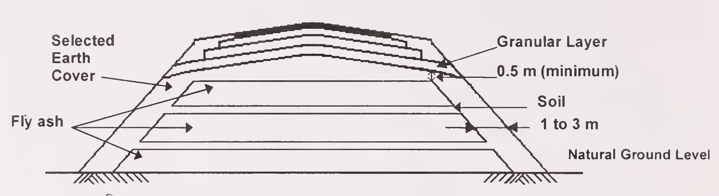
Intermediate soil layers are often provided in the fly ash embankment for ease of construction, to facilitate compaction of ash and to provide adequate confinement. Such layers minimise liquefaction potential also. Embankment with intermediate soil layers can be adopted in case height of the embankment is more than 3 m. The compacted thickness of intermediate soil layers shall not be less than 200 mm. One or more layers shall be constructed depending upon the design requirements. The vertical distance between such layers may vary from 1.5 to 3 m. The top 0.5 m of embankment should be constructed using selected earth to form the subgrade for the road pavement. Typical cross-sections of fly ash embankment with and without intermediate soil layers are shown in Figs. 1 and 2 respectively.11
Fig. I. Typical Cross-Section of Embankment with Alternate Layer of Fly Ash and Soil
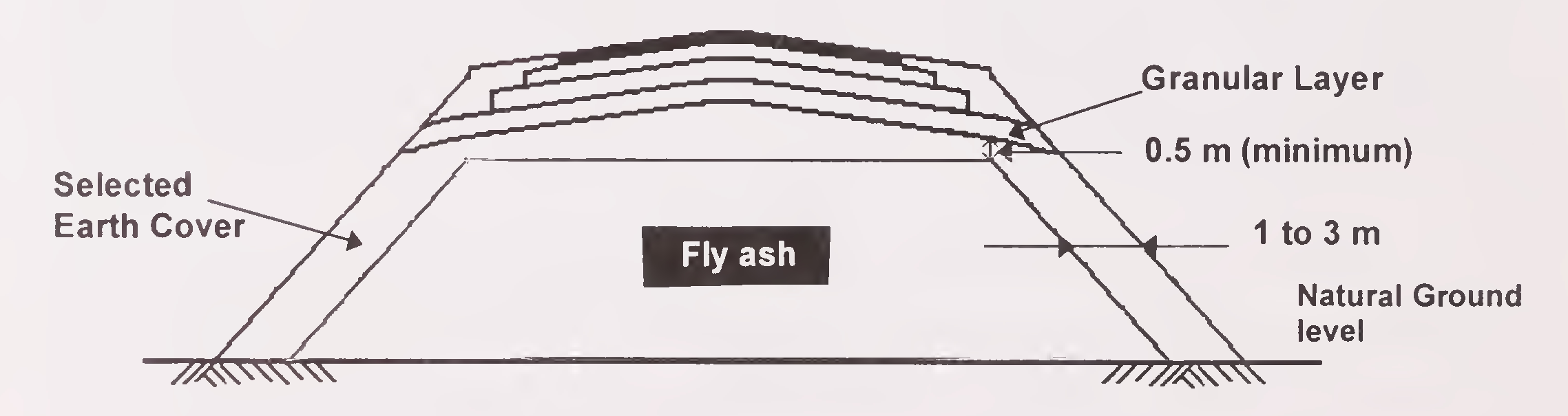
Fig. 2. Typical Cross-Section of Embankment with Core of Fly Ash12
Properly benched and graded slopes prevent the erosion of fly ash particles. Fly ash embankments should be benched at 4 to 6 m vertical intervals to drain surface water run-off to the ends of the embankment, rather than allowing full volume of the run-off to travel down the face of the embankment to the toe. Run-off from pavement surfaces should be collected and discharged into proper drainage system. For more details regarding drainage aspects, IRC:SP: 50-1999 may be referred.
This work consists of cutting, removing and disposal of trees, bushes, shrubs, roots, grass, rubbish, etc., from the alignment and within the area of road land which will accommodate road embankment, drains, and such other areas as specified on the drawings. During clearing and grubbing, the contractor shall take adequate precautions against soil erosion, water pollution, etc. All trees, stumps, etc., falling within fill area should be cut to atleast 500 mm below ground level and pits shall be filled with suitable material and compacted thoroughly so as to make the surface at these points conform to the surrounding area.
When constructing embankment using fly ash, the top soil from all areas to be covered by the embankment foundation should be stripped to specified depth not exceeding 150 mm and stored in stock piles of height not exceeding 2 m, for use in covering the fly ash embankment slopes, cut slopes and other disturbed areas where re-vegetation is desired. Top soil should not be unnecessarily trafficked either before stripping or when in stockpiles. Also, these shall not be surcharged or otherwise loaded and multiple handling should be kept to minimum.13
After the site has been cleared, the limits of embankment should be set out true to lines, curves, slopes, grades and sections as shown on the drawings. The limits of the embankment should be marked by fixing batter pegs on both sides at regular intervals as guides before commencing the construction. The embankment should be built sufficiently wider than the design dimensions so that surplus material may be trimmed, ensuring that the remaining material is of the desired density and in position specified, and conforms to the specified slopes. Bench marks and other stakes should be maintained as long as in the opinion of the engineer, they are required for the work.
If the foundation of the embankment is in an area with stagnant water, and in the opinion of the Engineer it is feasible to remove it, the same should be removed by pumping or any other means as directed by the Engineer, and the area of the embankment foundation should be kept dry. Care should be taken to discharge the drained water so as not to cause damage to works, crops or any other property. Construction of embankments underwater logged conditions shall be governed by provisions of IRC:36-1970.
Where necessary, the original ground should be levelled, scarified, mixed with water and then compacted by rolling so as to achieve minimum 97 per cent of MDD determined as per IS:2720 (Part 8)-1983 for the foundation soil. At locations where water table is high and the soil has potential for rapid and relatively great migration of moisture by capillarity, a granular layer, impervious membrane or a barrier of approved medium shall be inserted so that moisture is not able to rise to the subgrade level. Sand blanket of adequate thickness over full width of embankment can be adopted as an effective capillary cut-off. Medium grained sand can be used for this purpose. This will provide a working platform for the construction of fly ash fill and function14
as capillary cut-off. Provision of geotextile separating layer between drainage blanket and fly ash will help the drainage blanket to function efficiently and prevent intrusion of fly ash into drainage blanket. Drainage blanket can be nominally compacted with or without vibration. Bottom ash can also be used for construction of drainage blanket. Its grain size distribution is generally compatible with the grain size distribution of medium grained sand. Further guidance regarding capillary cut off design and its provision can be obtained from IRC:34-1970, 'Recommendations for Road Construction in Water Logged Areas'.
Where so directed by the Engineer, any unsuitable material occurring in the embankment foundation shall be removed and replaced by approved materials laid in layers, to the required degree of compaction. Any foundation treatment specified for embankment especially high embankments, resting on suspect foundations as revealed by borehole logs should be carried out in a suitable manner to the depth required. The depth of boreholes should be related to the height of embankment to be constucted.
Pond ash is typically delivered to the site in covered dumper truck to minimize loss of moisture and dusting. Pond ash generally contains enough moisture to prevent dusting and may even contain excess moisture to create road spillage during transport. In such cases, periodic inspection and lifting of ash from relatively dry areas of the pond would be needed.15
The fly ash may require on site temporary stockpiling if the rate at which the ash is supplied to the project site is more than the contractor’s demand for an efficient rate of placement. Such cases should be avoided to the extent possible, and in case stockpiling at site is inevitable, adequate precautions should be taken to prevent dusting by spraying water on stockpiles at regular intervals. Otherwise, the surface of the fly ash stockpile may be covered with tarpaulins or a thin layer of soil or other granular material not subject to dusting. Traffic movements may be restricted to those areas which are kept moist, to prevent tyres of passing vehicles dispersing ash into the air.
The side soil cover of required width shall be provided along with the core and mechanically compacted as the embankment progresses upwards. The addition of side cover subsequent to the construction of the core is prohibited. The fill material should be spread by mechanical means, finished by motor grader. The motor grader blade shall have hydraulic control so as to achieve the specified slope and grade. The most efficient lift thickness is a function of roller weight and vibratory energy. Smaller vibratory rollers with dead weights of 10 to 15 kN perform well on loose layer thickness of the order of 100-150 mm. Medium weight vibratory rollers with dead weights in the range 60-100 kN, provide satisfactory compaction for loose layer thickness of about 250 mm. When vibratory roller of dead weight 80100 kN are used, loose layer thickness upto 400 mm can be adopted if site trials as explained in section 4.7.3 show satisfactory compaction. When compaction is carried out using only static roller of80-100 kN weight, loose layer thickness shall not exceed 200 mm. The cover soil and fly ash should be laid simultaneously before compaction, to ensure confinement of fly ash. Clods or hard lumps in cover soil shall be broken to have a maximum size of 50 mm.16
Moisture content of the fill material shall be checked at the site of placement prior to commencement of compaction. Moisture content of fly ash laid for compaction shall normally vary from OMC (determined as per IS: 2720 (Part 8): 1983 to OMC ± 2 per cent. The moisture content limits can be varied depending on the weather conditions, by the Engineer-in-charge, provided specified compaction is achieved as revealed through actual site trials and there is no dust problem. It may be noted that grain shape and particle size of fly ash make the upper layers difficult to compact. At moisture contents higher than the appropriate range, fly ash may liquefy and would be difficult to handle and compact. Moisture content of cover soil shall be maintained at its OMC. Where water is required to be added to the fill material, it shall be sprinkled from a water tanker fitted with a sprinkler capable of applying water uniformly without any flooding. The water shall be mixed thoroughly by blading, discing or harrowing or by suitable means until uniform moisture content is obtained throughout the depth of the layer. If the material delivered to the construction site is too wet, it shall be dried by aeration and exposure to sun, till the moisture content is acceptable for compaction.
Fly ash can be compacted using vibratory or static rollers. Towed or self-propelled vibratory rollers are recommended. Regardless of the equipment used, fly ash must be compacted as early as possible after spreading. The contractor shall demonstrate the efficacy of the equipment he intends to use by carrying out compaction trials. The procedure to be adopted for these site trials shall be first submitted to the Engineer for approval. The use of test strips to develop compaction method specifications (optimum compaction procedure to satisfy density requirements) for the construction of the embankment is advisable. Typically several test areas are developed where a series of compaction trials can be conducted. In such trials, usually one parameter (such as, lift thickness, moisture content, etc.) is varied at a time while the others remain constant.17
Each layer of fly ash shall be thoroughly compacted to the specified density. When vibratory roller is adopted for compaction, two passes without vibration followed by 5 to 8 passes with vibration would be sufficient to compact individual layers. Mass per metre width of roller is recommended to be 2300-2900 kg/m and frequency range 1800-2200 rpm. The construction of fly ash core and earth cover on the sides should proceed simultaneously.
Each compacted layer shall be finished parallel to the final cross-section of the embankment. The following end product specifications as given in Table 2, have been suggested for construction of fly ash embankments.
| Minimum dry density after compaction as percentage of MDD IS:2720 (Part 8)-1983 | 95 % |
| Minimum dry density after compaction when used in bridge abutments - for embankment length equal to 1.5 times the height of the embankment | 100 % |
At locations where compaction of the ash fill/earth is impracticable using rollers, such as, fill portions adjacent to masonry structures/steep abutments or around concrete drainpipes embedded in embankment, hand held vibratory tampers shall be used for compaction. The required moisture contents and compaction requirements shall be same, as for the rest of the embankment, however, compacted layer thickness should not exceed 100 mm in such cases.
The Engineer may permit measurement of field density according to agreed procedure. Subsequent layers shall be placed only after the finished layer has been tested for its density requirements. The contractor shall maintain record of all such tests. When density measurements reveal any soft areas in the embankment, further18
compaction shall be carried out as directed by the Engineer. In spite of that if specified degree of compaction is not achieved, the material in the soft areas shall be removed and replaced by approved material, moisture content brought to permissible limits and recompacted to the required density.
Embankment shall be constructed evenly over their full width and the contractor shall control and direct construction plant and other vehicular traffic uniformly across the width. Damage by the construction plant or other vehicular traffic shall be made good by the contractor with material having the same characteristics and strength as it had before it was damaged. Embankments shall not be constructed with steeper side slopes or to greater width than those shown in the drawings. Whenever embankment construction is to be taken up against the face of natural slope or sloping earth works face including embankments, cuttings, and excavations which are steeper than 1:4 (Vertical:Horizontal), such faces shall be benched immediately before placing the subsequent fill. A less permeable capping layer of selected earth should be constructed on the top of fly ash embankment, which would form the subgrade for the road pavement. The thickness of this layer should not be less than 500 mm.
The sulphate content in fly ash should be within the limits specified in section 3.3.1.8. The sulphate content of fly ash may sometimes cause concern about possibility of sulphate attack on adjacent concrete structures. While no reported failures have occurred, certain precautions are advisable, in case sulphate attack on concrete structures is suspected. These consist of painting the adjacent concrete faces with bitumen or compounds, which offer moisture protection to concrete. Corrosion of cast iron, lead, copper, PVC or terra cotta19
pipes would be minimum due to contact with fly ash. There have been reported failure of aluminium conduit materials buried in fly ash. If protection of pipes is necessary, polythene sheeting, bituminous coating or embedding and backfilling with inert materials, like, suitable soil of minimum cushion thickness of 500 mm shall be adequate.
Where significant volumes of seepage are encountered, pipes should be used to drain the water out of the embankment area. Perforated pipe is usually placed in the vicinity of seep. One-third solid wall pipe with two-third slotted portion can be used to drain the water out of embankment area. PVC or ABC pipe materials are preferred because of their long-tenn performance. Analysis should be performed to confirm that they provide adequate wall strength to support the expected embankment loads. To prevent the internal erosion of the fill, filter protection should be provided around the pipes.
Finishing operations shall include the work of shaping and dressing the shoulders/verge/road bed and side slopes to conform to the alignment, levels, cross-sections and dimensions shown on the drawing or as directed by the Engineer subject to the tolerance. Both upper and lower ends of side slopes shall be rounded off to improve appearance and to merge the embankment with the adjacent terrain. In case turfing is proposed, top soil should be provided so that after seeding, a dense cover can develop. The depth of top soil should be sufficient to sustain plant growth, the usual thickness being 75 to 100 mm. Slopes shall be roughened and moistened slightly before the application of top soil in order to provide satisfactory bond. Embankments constructed in flood prone areas should be protected by stone pitching as per the provisions of IRC: 89-1985.20
Quality of compacted material shall be controlled through periodic checks on the compaction process or the end product, singly or in combination as directed. The end product must conform to the specifications.
If fly ash from more than one source is being used at the project site, monitoring must be done to identify the ash type being placed. The tests required to be conducted on fly ash to be used as borrow material for embankment are indicated below. The frequency of testing indicated refers to the minimum number of tests to be conducted. The rate of testing must be stepped up as found necessary, depending on the compaction methods employed at the project.
The samples collected for testing moisture content should be representative of the material being placed. Because fly ash may air dry relatively rapidly, samples should not be taken from the surface of the lift, but should represent the overall moisture content.
Control shall be exercised on each layer by taking at least one measurement of density for each 1000 square metres of compacted area, or closer as required to yield the minimum number of test results for evaluating a day’s work on statistical basis. The determination of density shall be in accordance with IS:2720 (Part 28)-1974. Test locations shall be chosen by random sampling technique. The number of tests to be conducted and acceptance criteria shall be as outlined in MOST Specifications for Road and Bridge Works, Section 900.21
REFERENCES
1. IS:2720 (Part 2)-1973, Methods of Test for Soils - Determination of Water Content, Bureau of Indian Standards, New Delhi.
2. IS:2720 (Part 4)-1985, Methods of Test for Soils - Grain Size Analysis, Bureau of Indian Standards, New Delhi.
3. IS:2720 (Part 5)-1985, Methods of Test for Soils-Determination of Liquid and Plastic Limits, Bureau of Indian Standards, New Delhi.
4. IS:2720 (Part 8)-1983, Methods of Test for Soils - Determination of Water Content-Dry Density Relation Using Heavy Compaction, Bureau of Indian Standards, New Delhi.
5. IS:2720 (Part 28)-1974, Methods of Test for Soils - Determination of Dry Density of Soils in Pace, by Sand Replacement Method, Bureau of Indian Standards, New Delhi.
6. IS:2720 (Part 29)-1977, Method of Test for Soils - Determination of Dry Density of Soils in Pace, by Core Cutter Method, Bureau of Indian Standards, New Delhi.
7. BS: 1377-1975, Methods of Tests for Soils in Civil Engg. Proposes.
8. IRC:34-1970, Recommendations for Road Construction in Water Logged Areas, Indian Roads Congress, New Delhi.
9. IRC:36-1970, Recommended Practice for the Construction of Earth Embankments for Road Works, Indian Roads Congress, New Delhi.
10. IRC:75-1979, Guidelines for the Design of High Embankments, Indian Roads Congress, New Delhi.
11. IRC:89-1985, Guidelines for Design and Construction of River Training and Control Works for Road Bridges, Indian Roads Congress, New Delhi.
12. IRC:SP:50-1999, Guidelines on Urban Drainage, Indian Roads Congress, New Delhi.
13. IRC Highway Research Board Special Report 16, ‘State-of-the-Art: Reinforced Soil Structures Applicable to Road Design and Construction, Indian Roads Congress, New Delhi, 1996.
14. Ministry of Surface Transport, (now Ministry of Road Transport & Highways), Government of India, ‘Specifications for Road and Bridge Works’, 1995.
15. Fly Ash Mission, Department of Science & Technology, Government of India, Technical Reports on Characterisation of Indian Fly Ashes, (Prepared by IISc, Bangalore), 2000.
16. Electric Power Research Institute, California, ‘Fly Ash Design Manual for Road and Site Applications’ (Prepared by GAI Consultants), 1992.
17. CRRI Project Reports on Okhla Flyover Project and Second Nizamuddin Bridge Approach Embankment, Central Road Research Institute, New Delhi, 1999.22