This library of books, audio, video, and other materials from and about India is curated and maintained by Public Resource. The purpose of this library is to assist the students and the lifelong learners of India in their pursuit of an education so that they may better their status and their opportunities and to secure for themselves and for others justice, social, economic and political.
This item has been posted for non-commercial purposes and facilitates fair dealing usage of academic and research materials for private use including research, for criticism and review of the work or of other works and reproduction by teachers and students in the course of instruction. Many of these materials are either unavailable or inaccessible in libraries in India, especially in some of the poorer states and this collection seeks to fill a major gap that exists in access to knowledge.
For other collections we curate and more information, please visit the Bharat Ek Khoj page. Jai Gyan!
Indian Roads Congress
Special Publication 40
Published by
The Indian Roads Congress
Copies can be had from
The Secretary General, Indian Roads Congress
Jamngar House, Shahjahan Road
New Delhi-110011
NEW DELHI 1993
Price Rs. 200/-
(Plus Packing & Postage)
MEMBERS OF THE BRIDGES SPECIFICATIONS AND STANDARDS COMMITTEE
(AS ON 31.10.92)
| 1. | Ninan Koshi (Convenor) |
... | Addl. Director General (Bridges), Ministry of Surface Transport (Roads Wing), New Delhi |
| 2. | M.K. Mukherjee (Member-Secretary) |
... | Chief Engineer (B), Ministry of Surface Transport (Roads Wing), New Delhi |
| 3. | C.R. Alimchandani | ... | Chairman & Manaing Director, STUP (India) Ltd., Bombay |
| 4. | A. Banerjea | ... | A-5/4, Golf Green Urban Complex, Phase-1, 10th Street, Calcutta |
| 5. | L.S. Bassi | ... | Addl. Director General (Bridges) (Retd.), Hat No.42, NGH Society, New Delhi |
| 6. | P.C. Bhasin | ... | 324, Mandakini Enclave, Greater Kailash-II, New Delhi-110019 |
| 7. | M.K. Bhagwagar | ... | Consultng Engineer, Engg. Consultants Pvt.Ltd., New Delhi |
| 8. | P.L. Bongirwar | ... | Chief Engineer, B-9, Camp Amravati (Maharashtra) |
| 9. | A.G. Borkar | ... | Secretary to the Govt. of Maharashtra, P.W.D., Bombay |
| 10. | S.P. Chakrabarti | ... | Chief Engineer (B), Ministry of Surface Transport (Roads Wing), New Delhi |
| 11. | S.S. Chakraborty | ... | Managing Director, Consulting Engg. Services (India) Ltd., Nehru Place, New Delhi |
| 12. | Dr. P. Ray Chaudhuri | ... | 148, Sidhartha Enclave, New Delhi |
| 13. | B.J. Dave | ... | Chief Engineer (Retd.), 702, Sampatti, Maharashtra Society, Mithakal, Ahmedabad |
| 14. | Achyut Ghosh | ... | Director, METCO, Calcutta |
| 15. | M.B. Gharpuray | ... | 838, Shivaji Nagar, Poona |
| 16. | D.T. Grover | ... | Chief Engineer (Retd.), D-1037, New Friends Colony, New Delhi |
| 17. | H.P. Jamdar | ... | Secretary to the Govt. of Gujarat, R&B Department, Gandhinagar |
| 18. | C.V. Kand | ... | Consultant, E-2/136, Mahavir Nagar, Bhopal |
| 19. | A.K. Lal | ... | Engineer-in-Chief-cum-Spl. Secretary, PWD, Road Constn. Deptt., Patna |
| 20. | P.K. Lauria | ... | Secretary to the Govt. of Rajasthan, P.W.D., Jaipur |
| 21. | N.V. Merani | ... | Principal Secretary, Govt. of Maharashtra (Retd.), A-47/1344, Adarsh Nagar, Bombay-400025 |
| 22. | Dr. A.K. Mullick | ... | Director General, National Council for Cement & Building Materials, New Delhi |
| 23. | A.D. Narain | ... | Chief Engineer (Bridges), Ministry of Surface Transport (Roads Wing), New Delhi |
| 24. | James Paul | ... | Bhagiratha Engg. Ltd., Hemkunt House, 6, Rajindra Place, New Delhi |
| 25. | Papa Reddy | ... | Managing Director, Mysore Structurals Ltd., 12, Palace Road, Bangalore |
| 26. | S.A. Reddi | ... | 72, Zenia Abad, Little Gibbs Road, Bombay |
| 27. | Dr. T.N. Subba Rao | ... | 18E, Dhanraj Mahal, C.S.M. Marg, Bombay |
| 28. | G. Raman | ... | Deputy Director (General), Bureau of Indian Standards, New Delhi |
| 29. | T.K. Sen | ... | Chief Technical Consultant, M/s. Gilcon Project Services Ltd., Calcutta |
| 30. | K.B. Sarkar | ... | Chief Engineer (Bridges), Ministry of Surface Transport (Roads Wing) New Delhi |
| 31. | N.C. Saxena | ... | 1/36, Vishwas Khand-I, Gomti Nagar, Lucknow |
| 32. | M. Shivananda | ... | Engineer-in Chief-cum-Project Co-ordinator, Mysore (Karnataka) |
| 33. | P.N. Shivaprasad | ... | Chief Engineer (B). Ministry of Surface Transport (Roads Wing), New Delhi |
| 34. | R.P. Sikka | ... | Addl. Director General (Roads), Ministry of Surface Transport (Roads Wing), New Delhi |
| 35. | Mahesh Tandon | ... | Managing Director, Tandon Consultant Pvt.Ltd., New Delhi |
| 36. | Dr. M.G. Tamhankar | ... | Deputy Director, Structural Engg. Research Centre, Ghaziabad |
| 37. | P.B. Vijay | ... | Chief Engineer, Vigyan Bhavan Project, CPWD, New Delhi |
| 38. | The Director | ... | Highways Research Station, Guindy, Madras |
| 39. | The Director Std/B&S (Arvind Kumar) |
... | RDSO, Lucknow |
| 40. | The President, IRC (L.B. Chhetri) |
... |
Secretary to the Govt. of Sikkim, Rural Dev. Deptt., Gangtok - Ex-Offico |
| 41. | The Director General | ... | (Road Development) & Addl. Secretary to the Govt. of India - Ex-Offico |
| 42. | The Secretary (Ninan Koshi) |
... | Indian Roads Congress - Ex-Offico |
| Corresponding Members | |||
| 43. | Dr. N. Rajagopalan | ... | Indian Institute of Technology, P.O. IIT, Madras |
| 44. | Dr. V.K. Raina | ... | United Nations Expert in Civil Engg. (Bridge & Structural), RIYADH (Saudi Arabia) |
| 45. | Shitla Sharan | ... | Adviser Consultant, Consulting Engg. Services (I) Pvt.Ltd., New Delhi |
| 46. | Dr. D.N. Trikha | ... | Director, Structural Engg. Research Centre, Ghaziabad |
Many of the old bridges constructed in the past are showing signs of weakness and require rehabilitation. The performance of some of the reinforced and prestressed concrete bridges built in the last few decades has also not been entirely satisfactory. One of the major thrust areas in bridge development in future will be the strengthening of weak bridges and rehabilitation of distressed bridges. The Indian Roads Congress constituted a Committee on Bridge Maintenance and Rehabilitation with a view to bringing out guidelines on various aspects of bridge management. Guidelines on ‘Inspection and Maintenance of Bridges’ (IRC:SP:35) and ‘Evaluation of Load Carrying Capacity of Bridges’ (IRC:SP:37) finalised by the Committee have already been published. The Committee has now finalised ‘Guidelines on the Techniques for Strengthening and Rehabilitation of Bridges’ which has received the approval of the IRC Council for publication.
Strengthening and rehabilitation need expert knowledge and specialisation. These guidelines cover common procedures for assessment of distresses in bridges, selection of techniques and materials as also approach to remedial measures and formulation of suitable repair plans.
They also include mention of some of the State-of-the-Art techniques for testing and repair which are yet to be adopted in India. The bibliography at the end is also a departure from the format of normal guidelines and indicate to the user the scope for further enquiry in the concerned areas.
Rehabilitation of bridges is an emerging area of activity which is bound to gain in importance in the coming years. This publication is the first document of its kind giving all the required information at one place. However, it is to be looked upon as a living document of suggested good practice which will need periodic review. Any comments or suggestions for future revision would be appreciated.
These guidelines fulfil a genuine need of the bridge engineering profession in this country and I am confident that their application will help practising engineers both in the design office and in the field in carrying out bridge rehabilitation works effectively and efficiently.
Director General (Road Development)
Government of India
Ministry of Surface Transport
(Roads Wing)
NEW DELHI, May, 1993
GUIDELINES ON TECHNIQUES FOR STRENGTHENING AND REHABILITATION OF BRIDGES
The Indian Roads Congress constituted a Committee on Bridge Maintenance and Rehabilitation (B-10) in January, 1988 in order to look into the various aspects, policies and guidelines for the general subject of bridge maintenance and rehabilitation. The Committee has already finalised “Guidelines for Inspection and Maintenance of Bridges” and “Guidelines for Evaluation of Load Carrying Capacity of Bridges” and these have already been published as IRC:SP-35 and IRC:SP-37 respectively. The present guidelines on ’Techniques for Strengthening and Rehabilitation of Bridges’ is the third in the line. The Bridge Maintenance and Rehabilitation Committee was reconstituted in January, 1991 and the Personnel of the reconstituted Committee are given below: (as on 31.10.92)
| N.V. Merani | ....Convenor |
| A.G. Borkar | ....Member-Secretary |
| Members | |
| P.C. Bhasin | S.A. Reddy |
| S.S. Chakraborty | Dr. N.S. Rangaswamy |
| S.P. Gantayet | N.C. Saxena |
| C.V. Kand | S.R. Tambe |
| P.Y. Manjure | M.K. Saxena |
| A.D. Narain | Surjit Singh |
| M.G. Prabhu | N.G. Thatte |
| Dr. T.N. Subba Rao | Maj. V.K. Verma |
| M.V.B. Rao | Director, H.R.S. |
| Ex-Officio | |
| President, IRC (L.B. Chhetri) D.G. (R.D.) | |
| Secretary, IRC (Ninan Koshi) | |
| Corresponding Members | |
| S. Sengupta | Dr. M.G. Tamhankar |
| Dr. Anil Kumar | M.R. Vinayak |
| Mahesh Tandon | |
The Committee had appointed a Sub-committee for preparing the draft of the document for the present guidelines. The Sub-committee comprised Shri A.G. Borkar (Convenor), S/Shri P.S. Gokhale, P.Y. Manjure and D.K. Kanhere. At the stage of finalisation Shri N.G. Thatte was also associated. The Committee held two meetings and finalised the guidelines in the meeting held on 7th September, 1991. The guidelines are to be looked upon as document on suggested "good practices" and not as "mandatory specifications". The Guidelines are meant to be a living document needing on-going review periodically. The guidelines approved by Committee were considered and approved by the Bridges Specifications and Standards Committee in their meetings held at Jaipur on 29-11-91 and at New Delhi on 21/22-10-92 subject to certain modifications. Later on the modified guidelines were approved by the Executive Committee and the Council in their meetings held at New Delhi and Patna on 11th November, 1992 and 28th November, 1992 respectively.
The deterioration of bridges is a world-wide phenomenon and the causes for this are also well known, such as inadequate design and construction, overloading,lack of adequate maintenance, atmospheric effects, unforeseen events like abnormal floods, earthquakes etc., and lack of knowledge of the durability and long term behaviour of structural concrete. Increasing number of bridges in the country would require major repairs for rehabilitation/strengthening. The problems faced are loss of traffic safety or reduction of structural strength with the resultant necessity for load limitations and in some cases premature bridge deterioration needing replacement. These could be avoided if adequate funds are devoted for timely repairs. Attention in the next few decades, therefore, is likely to be focussed on the preservation of integrity of large number of bridges built over the previous decades, through systematic maintenance and timely repairs.
The scope of these guidelines is as under :
A list of areas requiring further research and development has also been added in the end for information.
Though in the separate guidelines for inspection and maintenance of bridges the definitions of various operations have been given, for the convenience of the users the same are reproduced below :
This is defined as the work needed to preserve the intended load carrying capacity of the bridge and ensure the continued safety of road users. It excludes any work leading to improvement of the structure, whether by strengthening to carry heavier loads, by widening or by vertical realignment of the road surface. The maintenance operations begin with the opening of the bridge to traffic. (In fact a bridge member starts ageing the day its concrete is poured). It excludes repairs of any damage caused by exceptional causes like landslides, earthquakes, cyclones, fire etc., but it includes preventive maintenance.
These activities also meet the above definition of maintenance, but are larger in scope and cost, than maintenance. Rehabilitation operations aim at restoring the bridge to the service level it once had and has now lost. In some cases this consists of giving the bridge the service level which was intended, but which has never been attained, because of the deficiencies in the original design or construction.3
These aim at upgrading the level of service of a structure. The basic parameters to be taken into account in such improvements are :
Load carrying capacity and
Geometric parameters (width of carriageway, footpaths, vertical clearance etc.)
These works are required to be carried out when the whole structure or atleast its major components are required to be replaced, being beyond the economic level of repairs/ rehabilitation.
Rehabilitation or Strengthening of bridges may become necessary under various conditions, such as :
The bridge structures must, during their service life, have a specified level of safety and serviceability under the design working loads and the anticipated conditions of use. To achieve this purpose, a good bridge management system is essential. Management system as well as the maintenance policy have been dealt with in the "Guidelines on Inspection and Maintenance of Bridges" IRC:SP-35. In this Chapter, it is proposed to elaborate the same specifically for rehabilitation/strengthening of bridges.4
Road networks and bridges thereon are regarded as permanent installations. The bridges, however, generally deteriorate with passage of time and the society’s needs and requirements in regard to established road networks also change continuously. The former leads to need for rehabilitation and the latter to strengthening, widening of existing bridges. Regardless of whether it is a question of construction of a new bridge (s) or the rehabilitation / strengthening of an existing bridge, the work cannot be accomplished satisfactorily unless there is a reasonable understanding of society’s needs with respect to bridges as well as the requirements, needs and changes the present and future bridge stock may impose on the Bridge Authority. The following factors, therefore, need to be considered :
Both in developing countries and highly developed countries, the traffic volumes and axle weights have been observed to grow continuously, more so in developing countries. The gross weight of vehicles and the axle loads have also had a strong upward trend during the recent decades. As the cost of pay-load-ton transportation falls with gross vehicle load, the tendency is to carry as much load as possible on a single vehicle. The reason for increasing axle loads is thus an economic reason. Another important factor to be considered in traffic loads is the size of exceptionally heavy vehicles. The growth in traffic volumes and axle weights have thus to be considered for determining the strengthening measures.
As the awareness of environmental damages increases in the public mind, there will be more demands from them for protection against environmental damages.
The more complex the design of bridges, the more difficult it is to strengthen or rehabilitate the structure. The higher cost related to repairs and rehabilitation of such structures can sometimes make replacement more economical.5
These relate to the continuous changes in public values in regard to willingness to pay the additional cost for traffic safety and serviceability.
The increased importance of strengthening and rehabilitation of bridges can be characterised by -
The individual decision considerations will vary in accordance with the size and importance of bridge in question. For rehabilitating/strengthening major bridges,elaborate analytical techniques for evaluation of various solutions may be applied but an ordinary rehabilitation and strengthening work of minor bridges may be carried out in accordance with the general principles. In all cases, however, it should be ensured that available funds are allocated in accordance with the Authority’s overall objectives and policies. The general policy must take into account the number of parameters already described in para 2.2 above. In principle,the decision - which may vary from no action, some degree of temporary action, full rehabilitation or strengthening to, a replacement - could be reached through a cost-benefit analysis. However, such an approach may prove to be laborious in day-to-day operations and perhaps unjustified in majority of cases. A simple operational and robust framework for decision making is, therefore, advisable, as given below.
The bridges may be divided into elements, with relatively short-life-spans such as pavements, water- proofings, expansion joints, paint etc., and the bridge elements with long-life spans such as structural elements in bridge decks, columns, piers, foundations etc. Such division between6
short-life and long-life bridge elements is useful because of the stronger economic motivation to rehabilitate and strengthen long life elements than short life elements. A division between ordinary bridges and major or important bridges is also warranted while considering difference in technology and economy. On traffic considerations a division between bridges on rural roads, state highways, national highways and expressways also appears necessary. Similarly division on environmental considerations may also be necessary.The general policy for rehabilitation/strengthening of bridges must, therefore be based on the following factors :
Note. : Important bridges shall be those bridges which are on vital links or on links of strategic importance and all major bridges on national highways and major arterial State Roads. This definition is purely for the purpose of this guideline.
Apart from the factors given above, the policy decisions will have to be within certain parameters such as:
The best strategy can only be determined in the light of
The various steps involved in working out a plan for rehabilitation/ strengthening could be as below :
(a) Evaluation of the Structure from Documented Data Base and Inspections
These have been described in the Guidelines for Inspection and Maintenance of Bridges (IRC : SP-35).
(b) Locating Damages /Defects/Distresses
The deterioration of a structure can often be found visually through visible signs of damage. Therefore visual inspection by an experienced engineer is a vital step in the chain of further follow-up actions. A routine or principal inspection provides a detailed description of some of the damages where an assessment of the structure may become necessary.
The use of various testing methods may become necessary to complement the results of the visual inspection of the structure. Testing techniques and equipment should be determined relative to the extent and type of deterioration or damage and to the importance of structure (consequences of failure).To the extent possible, non-destructive test methods should be used. If necessary, the results of these tests may be8
supplemented and/or calibrated by sampling procedures in accordance with the small step principle, that is, when deficiencies are discovered from a minimum number of specimens (a small sampling) the investigation may require a more detailed analysis. These procedures are standardised.
(c) Analysis of, Causes of Damages/Defects and Distresses
The purpose of an evaluation of a distressed structure is not only to determine the effect of damage to the structure’s life expectancy/load carrying capacity, but also, and perhaps more importantly, a determination to the possible extent, of its cause so as to intelligently determine an effective retrofit. Before repair plan is implemented, the cause of the damage has to be removed or the repair measures have to be designed to accommodate the cause and protection against it in future. Otherwise the risk of repetition of damage will continue to exist.
(d) Evaluation of Results of Structural Assessment
Data resulting from the investigation of a damaged structure including monitoring of its distress, form the basis for the decision as to what corrective action must be undertaken. This depends on type and extent of the damage.
An initial concern should be as to whether or not there is a risk of failure to the damaged structure. If this risk is present,the first course of action must be to immediately provide an adequate auxiliary support mechanism and to reduce the loads to remove the risk. Where minor damage exists a determination must be made as to whether the damage is stable or will propagate with subsequent service loading. This is often a difficult and subjective assessment made on the basis of a visual examination until it can be verified with calculations. The elements of time and/or the harshness of the environment become important parameters when either the load carrying capacity is being diminished by deterioration (corrosion etc.) or when the load carrying capacity has to be increased (increased traffic load). Some evaluations will relate to whether or not an economically effective repair plan9
can limit or contain damage and thus can enhance the effective life of a structure. In some instances, an evaluation will be concerned with the degree of urgency required to implement a repair plan because of the advanced stage of damage.
The urgency of repairs, strengthening or replacement must be evaluated in a technical sense along with realistic cost estimates so that proper priorities can be established in budget planning. The question of urgency must also consider an estimation of remaining life expectancy. Although assumptions in a time dependant damage process are at best subjective, their evaluation will make an assessment of the degree of urgency less complex. Approximate estimations of life expectancy are valuable where damage is related to time dependent deterioration, e.g. corrosion of reinforcement. However, because of inherent uncertainties, the estimate will have to be presented in terms of upper and lower probability limits.
In some cases, it may be necessary to evaluate the load carrying capacity of the bridge. Guidelines for this evaluation have been issued separately (IRC : SP-37). Derating and/or regulated traffic options need also to be examined in these cases.
(e) Design of Repairs for Rehabilitation/Strengthening Works :
The most important step in the design of repairs for rehabilitation and/or strengthening work is a careful assessment of the existing structure. The purpose of this assessment is to identify all defects and damages, diagnose their causes and to evaluate the present and likely future adequacy of the structure.
Generally the structural design for repairs shall conform to the relevant IRC Codes. However, it must be recognised that the repairs for rehabilitation/ strengthening is a special type of work and many a time accurate structural analysis may not be possible both for the assessment of the existing strength as well as for the repairs for rehabilitation/strengthening. At the10
same time, the design in some cases may have to account for effects of secondary stress and composite actions. When the structural system is complex for accurate analysis, specifications more conservative than IRC specifications may have to be adopted. On the other hand, in certain special cases consciously permitting overstress may become unavoidable due to construction difficulties and thus calculated risk may have to be considered. The designer of the rehabilitation/ strengthening measures has, therefore, to be very judicious in his approach.
The technique to be chosen will depend on the needs, access, duration of lane closures for traffic, atmospheric conditions, etc..
(f) Proposals and Estimation of Costs :
The complexity and magnitude of the repair procedure will depend on whether
There are several options to be considered in evaluation of restoration of the functionality of a damaged structure such as:
The degree of restoration will depend on whether or not it is required to restore to the original or greater load carrying capacity. If for technical and/or economical reasons it is not feasible to achieve a complete restoration to original capacity and at the same time total11
replacement is not an acceptable option, a reduction of the applied
live load becomes mandatory. (Ref. IRC:SP-37).
The Bridge Authority in reaching a decision as to the course of action will have to evaluate not only the technically feasible options available,but also the costs of each option, time of execution, political considerations (economical impact on communities served by the facility), life expectancy associated with the various options available, any historical significance of the structure, any risks that may be involved with any changes in safety level or reduction in load carrying capacity etc.. The rehabilitation and/or strengthening of major bridges is a complete task requiring many a time inputs from several specialists. The bridge engineer, therefore, has to consult the experts in different fields to work out the appropriate repair plan.
Introduction
The types of road bridges built in India and usual distresses observed in each type of bridge are discussed in this Chapter. Special types of bridges like suspension bridges, cable stayed bridges, etc. have not been considered.
The following types of road bridges are known to have been built in India:
These again have the following forms
For the purpose of avoiding too many ramifications, further sub-divisions of forms and materials are not considered.
The most common defects noticed in such bridges are :
The most common distresses in R.C.C. bridges are as follows :
(a) Cracking: Cracks could be of different types. The significance of cracks depends on structure type,location of the crack, its origin and whether the width and length increase with time and load. These cracks can be due to several reasons like (1) plastic shrinkage,and plastic settlement, (2 )drying shrinkage, (3)settlement, (4) structural deficiency, (5) reactive aggregates, (6) corrosion of reinforcement, (7) Early thermal movement cracks, (8) Frost damage, (9) Sulphate attack and (10) Physical salt weathering.
Plastic shrinkage cracks occur within first few hours after initial set due to excessive bleeding and rapid early drying and result into loss of bond to bars and exposure of reinforcement. Thermal contraction cracks occur within first few weeks in thick walls and slabs due to excessive heat generation. Drying shrinkage cracks occur in walls and slabs and take a few weeks to years for development due to loss of moisture. They create path of seepage and leakage. Cracks due to corrosion in reinforcement take several months or years and lead to rapid deterioration of concrete. Alkali aggregate reaction can be a cause of cracks on account of internal bursting force caused by expansive reaction of certain aggregates in high alkali content situations while frost damage can occur at any age in porous concrete. Cracks due to sulphate attack may take several years to develop mostly near or below ground level on account of sulphate salts in damp ground reacting with the hydrated cement constituents. Physical salt weathering requires many months to many years for development of cracks in the inter tidal and splash zone or just near ground level in desert terrain, leading to deposition of salts and volume changes and final disintegration.
Plastic shrinkage and drying shrinkage cracks result into loss of bond and could be cause of path for seepage and leakages. Thermal14
contraction cracks could result into exposure of reinforcement, seepage and leaking. The settlement cracks due to movement must be recorded and the cause established. Such cracks can be critical and affect the load carrying capacity of the bridge. Structural cracks may occur due to overstressing which in turn can be due to the overloads or due to under-designed members or due to deficiency in construction. These cracks must be evaluated depending on the location, size and apparent cause. Corrosion induced cracks are located directly above or below the reinforcement. Rust stains may be visible and such cracks can indicate loss of load carrying capacity with time. Cracks caused by chemical reaction, alkali silica reaction can lead to serious damages to the concrete and loss of strength and capacity.
(b) Scaling : Scaling is the manifestation on the surface of loss of concrete in patches. If the process continues, coarse aggregates can get exposed and become loose and disintegrated and may eventually get dislodged. Kerbs and parapet walls are particularly susceptible to scaling.
(c) Delamination : Delaminations are separations along a plane parallel to the surface of the concrete. These can be caused by corrosion of reinforcement. Bridge decks and corners of concrete beams,caps and columns are particularly susceptible to delamination and delaminations ultimately can cause spalling of concrete.
(d) Spalling : Spalling of concrete is generally recognised to be a serious defect as it can cause local weakening, expose reinforcement, impair riding quality of deck and with time can cause structural failure.Spall is a depression caused by separation and removal of surface concrete. Major causes of spalling are corrosion of the reinforcement, overstresses, etc.
(e) Leaching : Leaching is the accumulation of salt lime deposits white in colour on the concrete surface. These are noticed normally on the underside of concrete decks and along cracks on vertical faces of abutment walls,wing walls etc. These indicate porous or cracked concrete. Where salts (NaCl or Sulphates) are present, the migration of moisture associated with leaching may initiate severe early deterioration.15
(f) Stains : Most significant stains is that due to rust which indicates presence of corrosion. But absence of rust is not necessarily indicative of no corrosion.
(g) Hollow or Dead Sound : If tapping with a hammer or rod produces a ’dead’ sound, this is indication of low quality concrete or delamination.
(h) Deformations : These are the effects of distress which may show in the form of deflection, spalling, delamination, scaling, cracks etc.. Swelling or expansion of concrete is usually an indication of reactive materials. However, localised swelling may be caused by compressive failure of the concrete. Twisting of substructure or superstructure units may be evidence of a settlement of foundation problem.
(i) Excessive Deflections : This could be due to deficiency in the structural capacity of the superstructure or due to passage of abnormal loads. Time dependent stresses also can cause such deflections if the estimated values of creep are different from the actual values.
(j) Holes in Deck Slab : This could be due to local weaknesses in concrete or other causes.
Most of the forms of distresses in prestressed concrete are similar to those in RCC. However, certain special features are as under :
(a) Cracking : Cracking in prestressed concrete is an indication of a potentially serious problem. Horizontal cracks near the ends of prestressed members may indicate a deficiency of reinforcing steel, to cater for bursting stresses. Vertical cracking in the lower portion of the member not near the support could be due to serious overstressing or loss of prestress. Vertical crack in the bottom of the unit and at the support may be a result of restricted movement in bearings. Vertical cracks in precast members above the neutral axis of a prestressed member can be due to mishandling during transportation or erection but these cracks close when dead load of the deck is applied.16
(b) Leaching : Leaching is also evidenced in prestressed bridges and the associated moisture movements will aggravate any corrosion risk. Particular attention needs to be paid to the concrete or mortar adjacent to joints in prestressed concrete e.g. box girders.
(c) Stains : Rust stains in prestressed concrete indicate corrosion of prestressing cables and should be considered a serious threat to structural integrity of the member. No rust stain does not necessarily mean no corrosion.
(d) Spalling : Spalling in prestressed concrete is a serious problem and can result in loss of prestress.
(e) Excessive Deformations : In prestressed members, the abnormal deflections could also occur due to loss of prestress with time.
(f) Abnormal Vibrations : These could be due to slender members or combination of various reasons.
The defects in steel bridges will be :
Deterioration of Steel
(A more detailed scale of rusting will be found in DIN 53210 and ISO 4628/1-1978.)
Abnormal Deformations or Movements :
Fracture and Cracking:
The distresses are normally the same as those for the concrete and/or steel bridges. However it is usually observed that the distresses like cracks are more common at the interface between two materials due to horizontal shear, the shear connectors being either absent or being of insufficient capacity.19
Some of the normally observed distresses are:
Distresses in bearings and expansion joints manifest themselves in various forms and have been dealt with separately.
Although the normally observed distresses have been listed above, the bridge engineer should keep an open mind to observe any new type of unusual distress/behaviour during inspection or monitoring.
Most of the road bridges built in India in the past few decades, have been constructed in concrete. Similarly, in the next few decades also, concrete will continue to be the main material for bridges to be constructed. Considerable investigations and research have been done on the properties of concrete and the science of testing it and the diagnosis of distresses in it has been developed over these years although a lot still remains to be done. This chapter on testing and diagnosis is, therefore, devoted to’Concrete Bridges’.
A review of available drawings to identify vulnerable details should be done before investigation. Investigation is to be carried out at three levels, namely a visual survey to assess the overall integrity of the bridge,a general survey including a limited amount of physical testing to plan more detailed investigation and possible rehabilitation and finally a detailed survey to determine the extent and precise location of deterioration or damage for the purpose of evaluating the capacity of the structure. Careful planning is required20
to identify the required information on the human and technical resources which must be carried out under the supervision of an expert engineer, who can modify the procedures as the investigation progresses, depending upon the needs.
Broadly speaking, the visual methods are very useful to detect cracking, scaling, wear and abrasion; the electrical and the chemical methods are of some help for corrosion detection; ultrasonic methods are more suitable for crack detection, while the thermography and radar techniques are suitable for detecting delamination and scaling beneath bituminous surfacings. Radiography and air permeability techniques have only a limited applicability to detect corrosion and voids in grout.
Visual inspection by an expert who has previously handled similar situations is the essential preliminary step. The degradation processes are likely to become apparent (though not true for all prestressed concrete structures) much before the load bearing capacity gets seriously reduced as many advanced warning signs like spalling, rust stains would be available and corrosion and other types of defects like cracks, excessive deflections, excessive vibrations, loss of camber, malfunction of joints and hinges, deformation, performance of bearing, drainage system, water-proofing etc., should be observed. It is necessary to provide proper access to various components of the bridge to ensure a thorough inspection. But for sensitive details which cannot be inspected visually, drawings should be examined.
A variety of non- destructive testing methods have been developed and are under development for investigating different properties of concrete in addition to the vital visual inspection described earlier. Tests are aimed at assessment of strength and other properties and to locate and obtain comparative results indicating permeable regions, cracks or laminations and areas of lower integrity than the rest. It is essential to emphasise here, that it is not necessary to carry out all the tests in each case except the most relevant ones. Facilities for a number of tests are still not available in India, but have been mentioned as they might become available later. Also, not much may be achieved by spending time and money on carrying out other than the most essential tests in many cases. In fact, in some cases, engineering judgements could help decisions faster. The tests can be broadly21
classified under different groups as shown in the Table 4.1. Table 4.2 gives abstract of test for investigating potential corrosion of reinforcement in R.C. and prestressed concrete structures.
(i) Carbonation : The carbonation of concrete on the surface results in loss of alkaline protection of the cover over the steel against corrosion. Carbon-dioxide of atomosphere reacts with hydrated cement compounds causing reduction in alkanity of concrete and the process is referred to as Carbonation. The depth of the carbonation is measured by spraying on the freshly broken surface of concrete with 0.10 per cent solution of phenolphthalein. The concrete undergoes, a colour change (from purple red to colourless) when pH value is below 10. The colour of the concrete surface after the spraying indicates the depth of carbonation.
(ii) Sulphate attack : The concrete attacked by sulphate has a characteristic white appearance. The quantity of sulphate is estimated by the precipitation of barium sulphate and sulphate confined by identification of Calcium Sulpho Aluminate by X-ray or microscopy.
(iii) Chloride content : This test should be done under expert guidance and proper sampling procedures need to be evolved due to high variability of laboratory test results. The chloride content in concrete is measured in laboratory by Mohr’s method using potassium chromate as indicator in a neutral medium or by Volhard’s volumetric titration method in acidic medium. The presence of acid soluble chlorides in concrete beyond the permissible limit is considered as a corrosion hazard in concrete structures. Rapid tests for in-situ chloride determination are being developed.22
| Method | Principal applications | Principal Properties assessed | Surface damage | Type of Equipment | Remarks |
|---|---|---|---|---|---|
| 1 | 2 | 3 | 4 | 5 | 6 |
| Pull out test (cast-insert) |
Quality Control (in-situ-strength) |
Strength related | Moderate/ minor | Mechnical | Preplanned usage, surface zone test |
| Pull-out test (drilled hole) |
In-situ strength measurement | Strength Related | Moderate/ minor | Mechanical | Drilling difficulties on vertical surfaces of soffits. surface zone test |
| Break-off test | In situ-measurement | Flexural tensile Strength | Substantial/ moderate | Mechanical | High test variability, surface zone test, very good to check repair bond |
| Penetration resistance | In situ-measurement | Strength related | Moderate/ minor | Mechanical | Specific calibrations required, limits on minimum members size, surface zone test. |
| Surface-hardness | Comparative Surveys | Surface hardness | Very minor | Mechanical | Greatly affected by surface texture and moisture, surface test, unpresentative on concrete more than 3 months old, strength calibration affected by mix properties. |
| Initial surface absorption | Surface permeability assessment | Surface absorption | Minor | Hydraulic | Difficult to standardize in situ moisture conditions and to obtain watertight seal to surface, comparative test. |
| Surface permeability | Surface permeability assessment | Surface permeability | Minor | Hydraulic | Surface zone test, water or gas23 |
| Resistivity measurements | Durability survey | Resistivity | Minor | Electrical | Surface zone test, related to moisture content, indicates potential of reinforcement corrosion in zones of high risk |
| Half-cell potential measurements | Survey of reinforcement corrosion risk | Electrode potential of reinforcement | Very Minor | Electro-Chemical | Indicates only the probability of corrosion. Quality of results depends on moisture content. Placement of half cell has to be done carefully |
| Ultrasonic pulse velocity measurement | Comparative surveys | Elastic modulus | None | Electronic | Two opposite smooth faces preferably needed, strength calibration affected by moisture and mix properties, some surface staining possible |
| Acoustic emission | Monitoring testing | Internal crack development | None | Electronic | Increasing load required, not fully developed for site use. Not very reliable |
| Dynamic response techniques | Pile integrity | Dynamic response | None | Mechanical/ Electronic | Cannot yield bearing capacity |
| Electromagnetic measurement | Location and depth of reinforcement | Presence of embedded steel | None | Electromagnetic | Affected by magnetic- aggregates and unreliable for congested steel. |
| Radar | Location of voids or reinforcement | Relative density | None | Radioactive source or radiations generator | Some safety precautions, limit on member thickness |
| Radiography | Location of voids or reinforcement | Relative density | None | Radioactive source or generator | Extensive safety precautions, limit on member thickness. Essential for prestressed ducts24 |
| Radiometry | Quality control | Density | None | Radioactive source or generator | Safety precautions and limit on member thickness for direct method and back scatter method, surface zone test. |
| Neutron moisture measurement | Comparative moisture content | Moisture content | None | Nuclear | Surface zone test calibration difficult. Not of much use so far. |
| Depth of carbonation | Durability survey | Concrete Alkalinity | Moderate/Minor | Chemical | Good indication of extent of carbonation if area is well sampled. |
| Resonant frequency | Quality control | Dynamic elastic modulus | None | Electronic | Specially cast specimen required. Not very useful |
| Strain measurements | Monitoring movements in structure | Changes in strain | Minor | Optical, Mechanical, Electronic | Attachment & reading requires skill can only indicate changes in strain. |
| Movement measurements at joints | Monitoring movements | Changes in strain | None | Mechanical | Requires skill to read. |
| Crack movement demec gauges | Monitoring crack widths | Changes in strain | None | Mechanical | Requires skill to read. |
| Spall survey | Corrosion risk | Indicates extent of corrosion damage | None | Physical recording of all spalls, depth of rebar, thickness of corrosion and spalled concrete for chlorides and carbonation25 |
| Techniques | Direct | Indirect | Non-Destructive | Semi- Destructive | Destructive | Corrosion | Remarks | ||
|---|---|---|---|---|---|---|---|---|---|
| Rate | Defect | Cause | |||||||
| 1 | 2 | 3 | 4 | 5 | 6 | 7 | 8 | 9 | 10 |
| Visual Inspection | X | X | X | Essential | |||||
| Weight Loss | X | X | X | Limited use | |||||
| Pit depth | X | X | X | Limited use | |||||
| Electrical Resistance Probe | X | X | X | Useful | |||||
| Linear Polarisation | X | X | X | Limited use | |||||
| Half Cell Potential | X | X | X | Useful | |||||
| Carbonation | X | X | X | Essential | |||||
| Covermeter | X | X | X | Essential | |||||
| Chloride Analysis | X | X | X | Essential | |||||
| Cement Content | X | X | X | Limited use | |||||
| Moisture Content | X | X | X | Limited use | |||||
| Resistivity | X | X | X | Useful | |||||
| Water Absorption | X | X | X | Limited usel | |||||
| Concrete Strength | X | X | X | Useful26 | |||||
| Delamination | X | X | X | Useful | |||||
| Ultrasonic Method | X | X | X | Limited use | |||||
| Hammer | X | X | X | Useful | |||||
| Gamma Radiography | X | X | X | For Prestressed Concrete only | |||||
| X-Ray Photography | X | X | X | -do- | |||||
| Winder Probe | X | X | X | Limited use | |||||
| Coring | X | X | X | limited use27 | |||||
(i) Schmidt hammer and other tests : These are used to measure hardness of concrete surface which can be related to its strength. The instrument used is very handy. The pull-out methods and penetration resistance techniques are also adopted for estimation of strength of concrete and assessment of its overall quality.
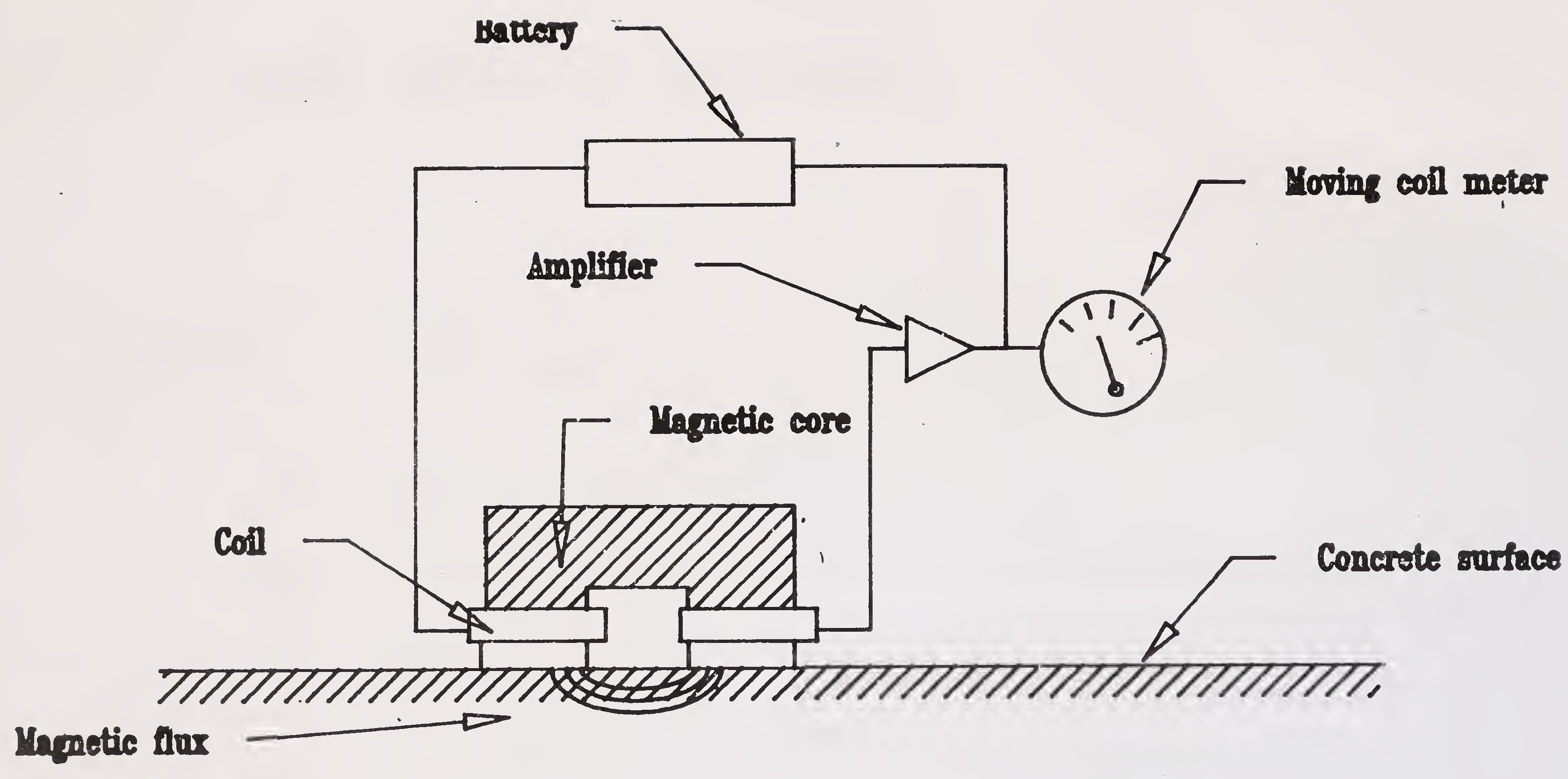
(ii) Magnetic methods : These are methods used to determine the position of reinforcement with reference to the surface of concrete and thus adequacy or otherwise of the cover over the reinforcement can be assessed. Pachometers detect position of reinforcement and measure the depth of cover. A battery is used to generate magnetic field which gets distorted where there is steel in the vicinity of the probe. Portable battery operated cover-meters (Fig.4.1) can measure the cover with an accuracy of 5 mm upto a depth of about 75 mm.
(iii) Radar technique : A high frequency pulsed radar can be used to detect deterioration in concrete decks. The echos produced from the pavement surface and the interface of the bridge deck concrete, in case of bituminous surfaced bridge decks, are very distinct so that thickness can be measured accurately, (Fig. 4.2). Short duration pulses of radio-frequency energy are directed into the deck portion and are reflected from any interface and the output is displayed on an oscilloscope. The interface can be any discontinuity or differing dielectric, such as, air to surfacing to concrete or cracks in concrete. A permanent record can be stored on magnetic tape and the unit is normally mounted on a vehicle and data are collected as the vehicle moves slowly across the deck.
(iv) Radiography : Radiographic techniques are applied on the prestressing cables to detect defects in the cable and to examine the quality of grouts within the ducts. Most applications involve transmission of wave energy rather than the reflection or refraction methods. The emerging radiation is detected by photographic emulsion or by a radiation detector. The former is called radiography and the latter radiometry. The back-scatter techniques based on reflected28
Fig.4.1 Simple covermeter29
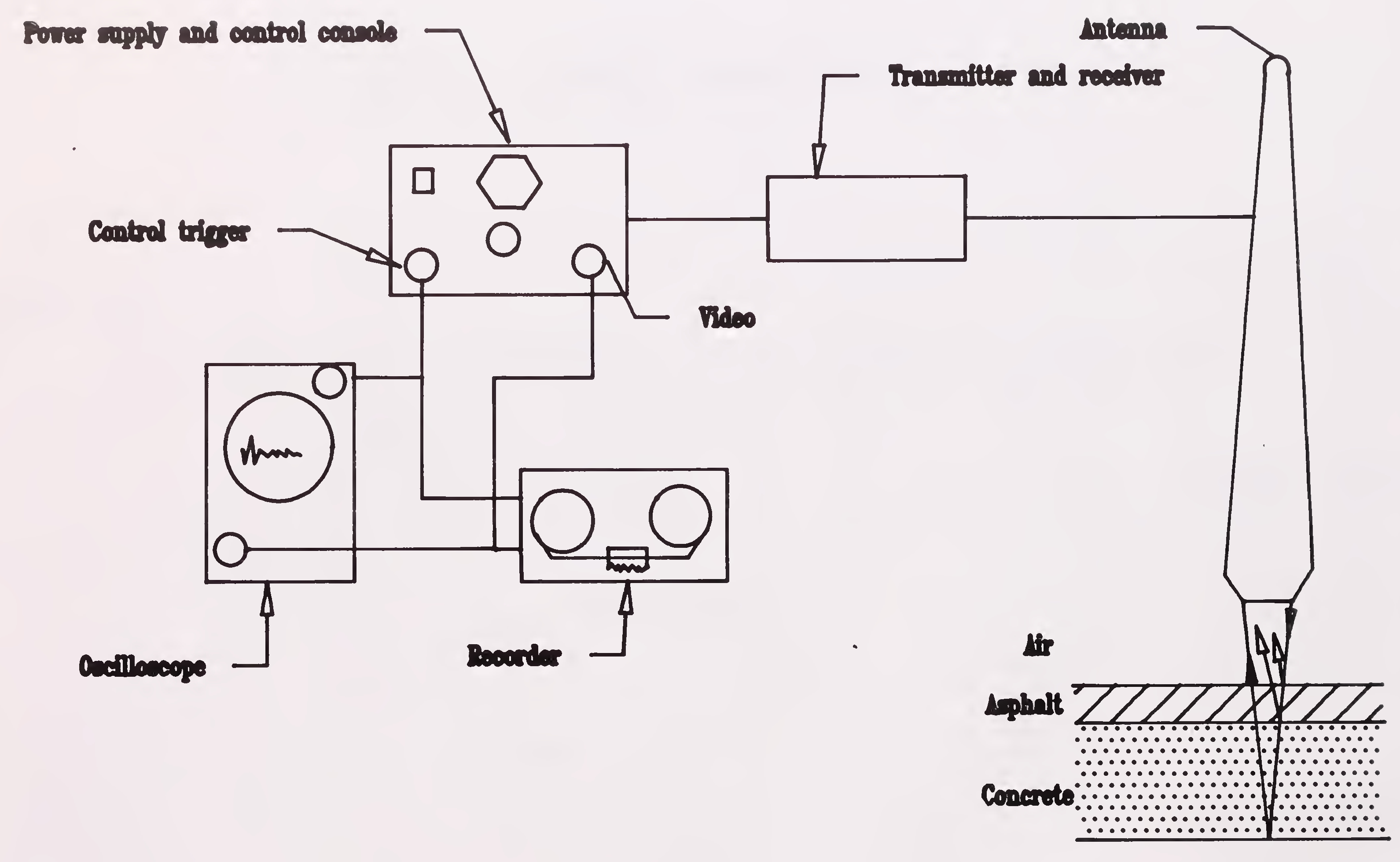
Fig.4.2 Elements of a radar system30
intensity of X-rays can be used to detect the voids in grout and testing strands or wires which are broken or are out of position. However, small amounts of corrosion will not be detected and the technique is suitable only for isolated cables without any other obstruction in the path of the wave.
(v) Thermography : Infra-red thermography is a method of detecting delamination in bridge decks and columns exposed directly to sun. The method works on the principle that discontinuity within the concrete, such as delamination, interrupts the heat transfer through concrete. The differences in surface temperature are measured by sensitive infra-red detection systems which consist of infra- red signal, control unit and a display screen. The images get recorded on photographic plates or video tapes. The equipment can be truck-mounted permitting a lane width to be scanned by a single pass. The main disadvantage of thermography is that while a positive result is valid, a negative result may not be always reliable because it relates to results under conditions prevailing at the time of tests. Nevertheless, the method itself has a considerable promise as a rapid screening tool for determining whether a more detailed investigation is required.
(vi) Nuclear and radioactive method : The density of concrete upto 100mm depth can be assessed by using the gamma-ray back scatter device. The concrete is irradiated from a portable neutron source and absorption of neutrons by chloride ions simulates emission of gamma radiation of a particular energy. The presence of moisture can be similarly detected by measuring the simulated emission of gamma radiation by hydrogen atoms. However, the readings would not give depth of penetration of chloride ions. The test is a highly specialised one.
(vii) Ultrasonic pulse velocity measurement : The quality of concrete can be assessed by passing through concrete the ultrasonic pulse and measuring the velocity, (Fig.4.3). Measured values may be affected by surface texture, moisture content, temperature, specimen size, reinforcement and stress. Co-relations with strength are difficult to make and will be31
influenced by types and proportions of mix constituents and maturity. Calibration on tested cores is essential.
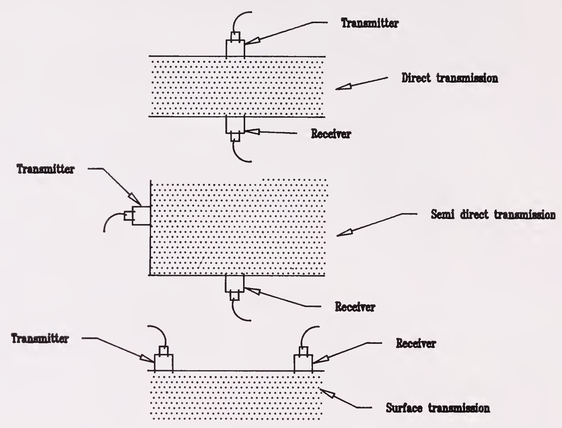
Fig.4.3 Methods of measuring pulse velocity through concrete
(i) Pull-out strength of hardened concrete : It is possible to assess the comparative strength of hardened concrete by co-relating it to the pulling force (required to pull the metal devices inserted in concrete). A large number of such tests need to be carried out.
(ii) Coring : This is a somewhat destructive method of assessment under which core of concrete from the structure is drilled with the help of a coring machine. The core is then analysed in a laboratory for various properties including its strength. Core drilling machines of the size of brief-case are available commercially.
(iii) Endoscopy consists of usually flexible viewing tubes which can be inserted into holes drilled in the bridge components or32
into a cable duct of the prestressed concrete. A light is provided by optical fibres from external source. The endoscopes are available with attachments for a camera or a TV Monitor and are used for detailed examination of parts of the bridge structure which cannot otherwise be assessed. They are useful in detecting voids in the grout, concrete, corrosion in steel etc. This test if required, should preferably be done in association with radiographics and should be done under expert guidance.
(iv) Other methods : Electrical corrosion detection device : The electrode (half-cell) potential of reinforcement embedded in concrete provides a measure of the corrosion risk and indicates whether electro- chemical reaction has taken place on the electrode surface. The electrical potential difference between the steel and electrode (concrete) is measured with copper/copper sulphate half-cell or copper calomel electrode or silver chloride electrode, (Fig.4.4). The pathfinder and potential wheel, marketed recently, are refined versions of copper/copper sulphate electrode for better scanning. However, this method does not give information on the rate of corrosion, and also it gives only the probability of activity of corrosion. However, it has been recently reported that C.E.C.R.I. Karaikudi has succeeded in giving quantitative indications of corrosion in steel by electrical devices (vide Appendix 1).
(v) Response to vibration : The objective of vibration testing is to relate the defects in the bridges to the changes in its dynamic characteristics. The vibration analysis of a structure carried out over a period of time measures loss of stiffness and not the loss of strength, although the former seldom implies loss of strength. However, a serious loss of strength in an individual member may occur before there is a measurable loss of stiffness in the overall structure. Sometimes, accelerometers are temporarily attached to the bridge and the traffic/wind induced vibrations are recorded. The modes of vibration and damping can then be determined by computerised analysis. Sometimes, a variable frequency sinusoidal force is applied at a point in the bridge the response at other points is measured which depends mainly on the fixity and stiffness of33
connections. With proper application, the cracks can also be detected by this method. The vibration methods show considerable promise although the methods of interpretation of results in terms of the type of defects and its cause are yet to be developed.
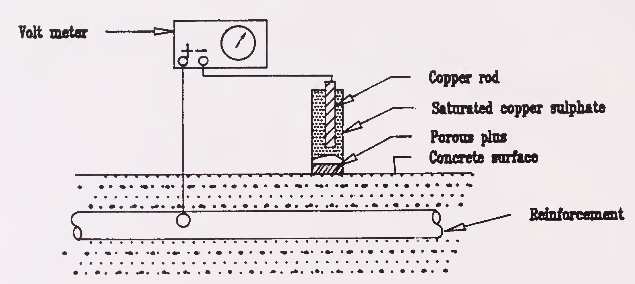
Fig.4.4 Electrical potential measurement of reinforcement
The various non-destructive and other evaluation methods have several limitations as there are various parameters influencing each test and many a time combination of different methods have to be used during investigations.
Recently, in-situ permeability testing equipment has also become available for assessing die quality of concrete although doubts are being expressed about the reliability of results.
A general summary of the capabilities of the various test methods to detect different forms of defects or deterioration is given in the Table 4.3. This Table provides comparison amongst the methods and can be used in planning an investigation.34
| Technique | Capability of Defect Detection | ||||
|---|---|---|---|---|---|
| Cracking | Scaling | Corrosion | Wear and Abrasion | Voids in | |
| Visual | G | G | P/G | G | N |
| Sonic | F | N | G | N | N |
| Ultrasonic | F | N | N | N | N |
| Magnetic | N | N | F | N | N |
| Electrical | N | N | G | N | N |
| Chemical | N | N | G | N | N |
| Thermography | N | Gb | N | N | N |
| Radar | N | Gb | N/P | N | N |
| Radiography | P | N | P | N | G/F |
| Air permeability | N | N | F | N | F |
| Water permeability. | N | F | F | P | F |
| G = good; F = fair; P = poor; N = not suitable; b = beneath bituminous surfacings. | |||||
The above techniques present possibilities of making an assessment of the overall condition of the bridge or changes in the condition and of detecting faults. But, it is often difficult to analyse the effects or defects or deterioration on the overall performance of the bridge or on the stresses in individual components. A full scale load test can, therefore, be useful. Load tests can be expensive and on larger bridges they require considerable planning, involve many people and demand the use of sophisticated equipment. Testing in remote locations can present additional difficulties. Particular care is needed for bridges with brittle failure modes. However, load testing can often be justified where the effect of defects and/or deterioration on load capacity cannot be determined by analysis alone. However, a decision to carry out full scale load testing should not be undertaken without a serious thought.The actual procedure for load testing for rating of bridges and interpretation of tests have already been described in IRC:SP:37. So the procedure for load testing is not described here; but principles and instrumentation and equipment used in load testing are given below :
(a) Bridge testing is both an art and a science. In its simplest form, load testing involves measuring the response of the bridge to a known applied load. Considerable experience is required to know where to locate gauges and to determine load increments and the maximum load to be applied to prevent damage to the35
bridge. The load is applied, usually by vehicles although occasionally by dead load or through cables, to induce maximum effects. Where measurement of stress at a given location under known load is all that is required, data processing may not be a major consideration. In other cases, the amount of data recorded is often extensive such that automatic data recording and analysis is highly desirable. It is also preferable that this be done on site as the test progresses so that deviations from anticipated behaviour are known and the necessary changes in procedure or equipment can be made. Because concrete properties are required to define stress values (from strain measurements), samples must be taken from the structure.
(b) Several types of strain gauges can be used in conjunction with load testing bridges and jacks can be used to determine reactions at the supports.
(c) Comparators are mechanical, electrical or electronic instruments used to measure the distance between studs attached to the structure. The distance between the studs is usuallty in the range of 50 to 200mm and the sensitivity of the instruments is typically 0.01 to 0.05 mm. The main application of comparators is to measure the change in width of a crack under load or over time.
(d) Resistance wire strain gauges are cemented directly to the material under investigations. Dummy gauges are incorporated in the electrical circuit to compensate for temperature effects. Strains, which are measured by the change in the electrical resistance of the gauges, can be determined very accurately, generally between 1 and 3 micro-strain. The interpretation of the result is, however, often difficult because of the small size of the gauges and the non-homogenous nature of concrete. Several gauges must therefore be attached to the structure in the area of interest in order to identify anomalous results. Resistance wire gauges are not suitable for use on cracked concrete because a change in strain may stress them beyond their linear range.36
(e) Rosette gauges, which contain three resistors set in a known angle (generally 45 degrees or 60 degrees), can be used to calculate the direction and magnitude of the principal stresses.
(f) Vibrating wire gauges consist of a metal wire stretched inside a tube which is embedded in the concrete. The wire is vibrated by an electromagnet and the frequency of vibration is measured, from which the strain in the concrete can be calculated. Since the gauge is about 150mm long, the results are not affected by localised heterogenetics in the concrete, but cracks cause the same kind of problems as with resistance strain gauges.
(g) Jacks can be used to measure the reactions at the supports of the structure. This may be required for such purpose as assessing the impact of thermal gradients, or the re-distribution of stresses due to creep, settlement or faulty construction. The technique consists of measuring the force and movement as the structure is raised. A relationship such as that shown in (Fig. 4.5) is obtained, from which the reaction at the support can be determined. This type of test is expensive and, in addition to the requirement for suitable jacking points,
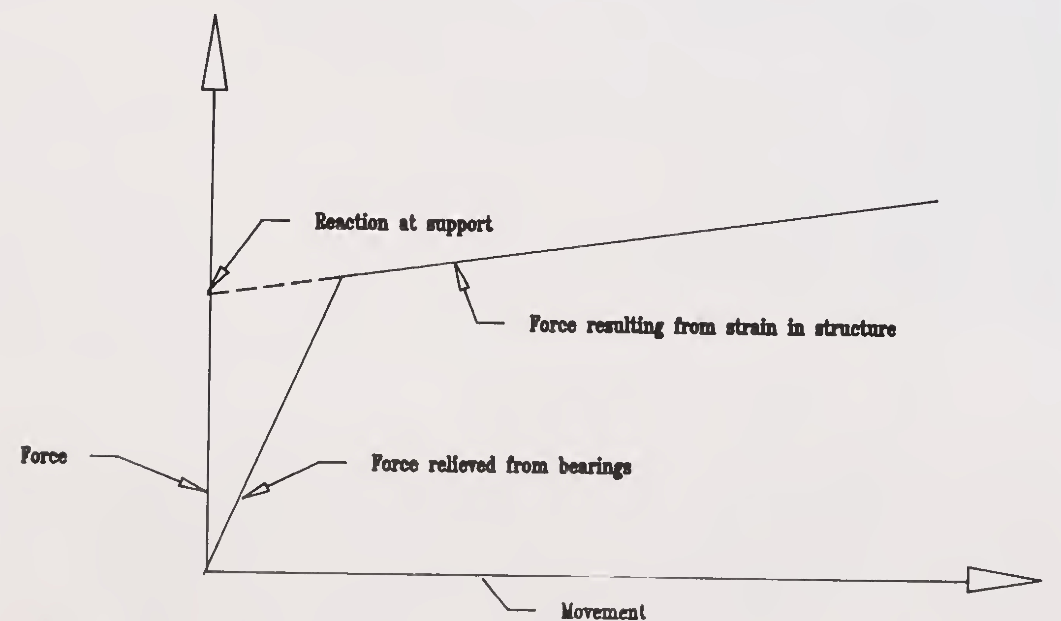
Fig.4.5 Tipical force-movement relationship resulting from jacking a support37
the deck joints must be removed together with any other feature which might interfere with the free movement of the jack. Using good quality, properly calibrated equipment, an accuracy of 0.3 to 1.0 per cent is attainable, with load cells. It may however be noted that even calibrated jacks are about ±5% accurate if only the hydraulic pressure is monitored.
It is intended to cover in this chapter only the more important techniques and materials used for bridge repairs and strengthening. The maintenance techniques described in the separate guidelines for inspection and maintenance of bridges are not repeated. The criteria for selection of materials and techniques for repairs and strengthening could be :
It is not possible to evolve a general method for repairs and/or strengthening of foundations. Each case has to be analysed individually and may require special investigations. Most repair works for foundations are in the category of protection and strengthening. Some examples are given below:
Note : Foundation movements can substantially increase the loads and moments in some parts of the superstructure by redistribution. This must always be checked for.
It is not possible to list causes of deficiency of underwater structures as they are too numerous. The same, also, applies to the combinations of conditions requiring repairs. Given the wide range of materials and repairs techniques the choice of the most appropriate technique is difficult. Table 5.1 gives a list of possible remedial measures according to the nature of the problems. Some of the repair works carried out for foundations are described below for information and guidance though, as already mentioned, each case has to be decided on its merit. Guidance could be obtained from IRC:89-1985 "Guidelines for Design and Construction of River Training and Control Works for Road Bridges".
(1) Erosion problems : Stone rip-rap is placed on a mattress at or beneath the channel bed level. The weight of the mattress sha11 be designed keeping in view the maximum velocity of flow but preferably shall not be less than 150 kg. per sq.m. The slope of the protective rip-rap should be between 1 in 3 ana 1 in 3.5. Heavier stones should be used for rip rap in case steeper slope is necessary.39
| Type of Repairs (Underwater & in splash zone) | Scour | Deterioration | Structural Damage | Structural Failure | Foundation Distress | ||||||||
|---|---|---|---|---|---|---|---|---|---|---|---|---|---|
| Concrete | Steel | Timber | Concrete | Steel | Timber | Concrete | Steel | Timber | Concrete | Steel | Timber | ||
| 1 | 2 | 3 | 4 | 5 | 6 | 7 | 8 | 9 | 10 | 11 | 12 | 13 | 14 |
| Replacement of Material | X | ||||||||||||
| Steel Piling | X | ||||||||||||
| Modification of Structure | X | ||||||||||||
| Training Works | X | ||||||||||||
| Cement/Epoxy injection | X | X | X | X | X | X | X | X | |||||
| Quick Setting Cement | X | X | |||||||||||
| Cement/Epoxy/ Polymer modified Mortar | X | X40 | |||||||||||
| Placing Concrete Underwater | |||||||||||||
| a) Underwater Bucket | X | X | |||||||||||
| b) Tremie Concrete | X | X | X | X | X | X | X | X | X | ||||
| c) Pumped Concrete | X | X | X | X | |||||||||
| d) Protective Coatings | X | X | |||||||||||
| e) Cathodic Protection (Experimental) | X | X | X | ||||||||||
| f) Splicing New Steel Section | X | X | X | ||||||||||
| g) Pile Jacket | X | X | X | X | X | X | X | X | X | ||||
| h) Wood Treatment | X41 | ||||||||||||
(2) Protection against scour : Excessive scour is one of the more frequent factors that may cause or lead to structural failure or distress of the foundation. The degree of damage depends on factors such as the stream bed material, the intensity of discharge, the silt charge, obliquity of stream flow and the shape of the structure.
For deciding the extent and type of repair arising out of excessive scour, ascertaining the causative factors, such as change in the alignment of the stream, an inadequate waterway or the presence of debris, is of great help. Determining the most effective solution to a scour problem is often difficult and may require model studies to be carried out.
Spur dykes, jetties, deflectors and other devices may be constructed to direct water away from a fill, bridge pier, or abutment. Caution is needed because only correctly designed and constructed training works are helpful in controlling scour and erosion. Repair of damages caused by channel scour may vary from simple solutions such as replacement of displaced material to complicated solutions like redesigning the footing, construction of training works or sheet piling, or other modifications of the structure or channel.
At sites, where soil erosion has occurred because of stream or tidal action, it is a common practice to place rock or rip-rap material in the void or to protect the replaced soil with rip-rap, bagged concrete rip-rap or grouted or wire enclosed boulders. Piers and abutments may be protected or repaired by placing sheet piling to keep material in place or to prevent further scour. Sheet piling should be driven to a depth where non-erodible soil conditions or rock exist. The overhead clearance required or under substructures may be a major disadvantage in using sheet piling. If supporting material has been removed from under a large area of the footing, consideration should be given to redesigning the foundation, including filling the void with concrete. In some cases, the footing may be extended by using sheet piling as forms for the extension and as stay-in-place protection against further scour. If scour has exposed supporting piles, it may be necessary,42
particularly if they are short, to drive supplemental piles that are part of the extended footing.
To restrict scour around piers it is also common to utilise what is known as ‘garlanding technique’. In this, very heavy concrete blocks or stones of designed weight are placed around the pier foundations below the bed level by excavation. The size of the garland and the weight should be properly designed.
It is advisable to consult experts before deciding/undertaking the solution of a serious repair problem.
(3) Foundations on soft rock subject to erosion can be protected by reinforced concrete curtain walls enclosing the footing or piles.
(4) Increasing the bearing capacity of the soil by injecting cement or chemical grout taking care that grout pressure does not exceed the overburden pressures.
(5) Rock or ground anchors are often used for abutments where protective slope had to be removed for say widening of navigable channel, road, etc. Normally a protective sheet pile wall is driven first in the case of ground anchors. Design and execution of rock ground anchors requires great care and should take into account all factors likely to affect the bearing capacity and durability of the anchoring system. Now a days, prestressed anchors are also used.
(6) Extension of existing foundations : This would be necessary while widening an existing bridge.
(7) Liquefaction of foundation soil : Some foundation failures during earthquakes could be the result of excessive soil movements especially due to liquefaction. There are two approaches to retrofitting that will mitigate these types of failures :
Some methods are available for stabilising the soil at the site of the structure. Each method should be individually designed making use of established principles of soil mechanics to ensure that the design is effective and that construction procedures will not damage the existing bridge. Possible methods for soil stabilisation include :
At a site subjected to excessive liquefaction,methods to improve the structure may be ineffective unless coupled with methods to stablilise the site.
(8) Underwater work : While dealing with underwater work, it will be relevant to refer to underwater inspection also. Inspection of underwater portions of the structures is very difficult because of the harsher environment, poor visibility, deposition of marine organisms etc. To do an effective underwater inspection, it is necessary to deploy properly trained and equipped supervisory personnel. The quality of inspection underwater should be equal to the quality of inspection above water. Clearing the marine growth from underwater portions of a bridge is almost always necessary. Visual inspection is a primary work of detecting underwater problems. In turbid waters, the inspector should use tactile examination to detect flaws, damage or deterioration. In some cases sophisticated techniques, ultra-sonic thickness gauges, computerised tomography or TV monitors may be required. After the initial identification of a trouble spot of the damage, for the purpose of detailed examination and carrying out repairs it may be necessary either to expose the member by means of a cofferdam and dewatering or by providing a small air-lock as described later.44
Normally, inspection of under water components of a bridge is carried out with the use of divers who are usually non-qualified as bridge inspectors. It would be useful to train some of the engineers in diving techniques so that they as qualified divers can interpret the observations in a more scientific way. Underwater photographic techniques are also available wherein damages are detected by divers who can then take photos of affected areas. Similarly, underwater cameras (mounted on diver’s head gears) can be used to scan the various components of submerged portions of the structure continuously and signals can be read on a TV monitor kept on the bridge deck.
A new technique using acoustic microscopy* measurements has been developed abroad for underwater study. In this, measurement of small electrical potential differences caused by corrosion current in sea water is combined with acoustic inspection to determine the crack width and depth. Computerised tomography is yet another recent method to locate voids and steel reinforcement in underwater concrete. A gamma ray source is collimated to form a flat fan of rays which are attennuated as they pass through the approach to a set of detectors. The source detector apparatus is rotated to obtain a series of projections through the same cross sections (Fig.5.1). It is, however, reported that this technique is not yet well developed and is reliable in laboratory conditions only. But, Sonar procedures for mapping scour are useful.
Placing of concrete under water can be carried out with the help of conventional underwater bucket or tremie concrete, although under certain conditions placing of pre-packed concrete or bagged concrete or pumped concrete may be more suitable. In all such underwater repairs the surfaces of the pile or well or pier have to be cleaned of the dirt and other foreign material and after removing the cracked and unsound concrete the surface is to be prepared for receiving new concrete. Suitable priming coat by materials like moisture compatible epoxy resin is helpful to ensure proper bonding. The piles or columns are substantially deteriorated through actions of corrosion or other factors can be provided with integral jackets which may or may not be reinforced depending on the thickness of the jacket. It is often useful to provide temporary cofferdam which can be fixed to the pile at the base and the water can be pumped out. Joint of the jacket at its ends has to be properly detailed out and treated with epoxy. Grouting with quick setting cement or epoxy can also be carried out where necessary.
* Not yet introduced in India45
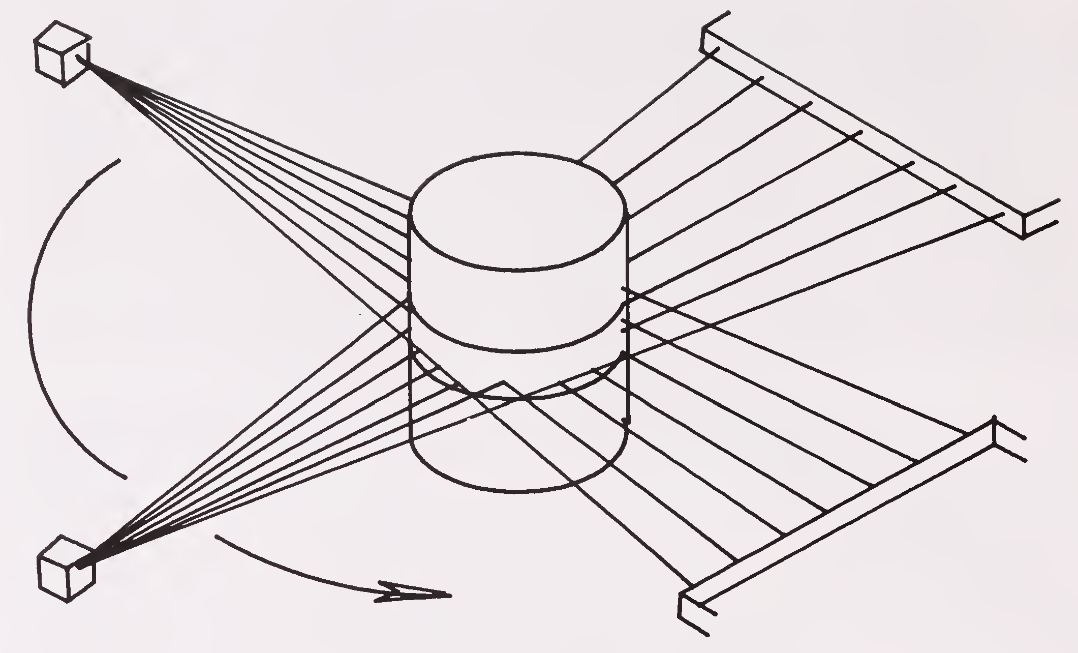
Fig.5.1 Scanning procedure for computerised tomography
Methods used by divers to perform underwater sealing and repairing of cracks by epoxy injections are similar to methods used above water, except that the epoxy surface sealer takes several days to harden sufficiently to withstand injection pressure. For underwater use, epoxies must be water insensitive. Before the application of epoxy surface sealer, cleaning is necessary. If oil or other contaminants are present in the cracks, and the epoxy is used for restoring the strength of the cracked concrete pier or pile instead of simply blocking the free entry of water in the crack, bonding will be improved by mixing detergents or special chemicals with a water jet to clean the crack interiors. After all cracks are prepared and sealed and the nipples positioned the low viscosity epoxy adhesive is injected under pressure into the crack network. A surface-mounted, positive-displacement pump is used to dispense the two components of the adhesive to the submerged injection sites where the components are mixed in the injection head as it is pressure-pumped into concrete.Water temperatures must be above 4 degrees centigrade. The adhesive cures to full strength in about 7 days. Cracks upto 2mm width may be sealed with straight epoxy resin (without filler). For wider cracks, the46
addition of a filler is generally required. Now-a-days, for underwater repair works, devices called ’Habitat’ are used. Habitat is a multi- cell metal unit open at the bottom with water- tight joints. This is installed around the member to be repaired. With compressed air, the Habitat is kept dry so that the divers can undertake repairs (Fig.5.2).
Various methods are currently used to prevent the corrosion of steel piling in sea water, including application of protective coatings, encasement of the steel in concrete or a combination of these procedures. Cathodic protection can also work well for this.
Existing masonry bridges are sometimes considered as historical landmarks and need preservation. Strengthening and widening will, therefore, mean maintaining the same appearance. Widening is usually not possible but strengthening can often be done. Strengthening of Masonry Bridges ensuring pleasant appearance is a delicate task and needs advice from experts in these fields.The following gives an idea of the general defects and remedial measures for such arch bridges in stone or brick masonry.
(i) Loss of Bond for the Crown stone: Flat jacks have been successfully used for pushing the stone back to its original position. Generally, low pressure cement grouting is done to strengthen the old mortar. The mortar is sometimes replaced by epoxy mortar also, though epoxy is not ideal.
(ii) Longitudinal cracks along the direction of traffic : It is possible to rake mortar joints and refill with cement mortar. However it must be mentioned that the depth of penetration is important as usually it is not possible to suspend traffic. If possible, the portion of earth fill could be removed to ensure that penetration is limited to masonry only. Fine cement grouting (injection) can be adopted for remedial measures. Generally it is cheaper and better to grout the cracks with cement than with epoxy.
(iii) Transverse Cracks : Injection of cement will provide a good bond between stones and brick masonry.47
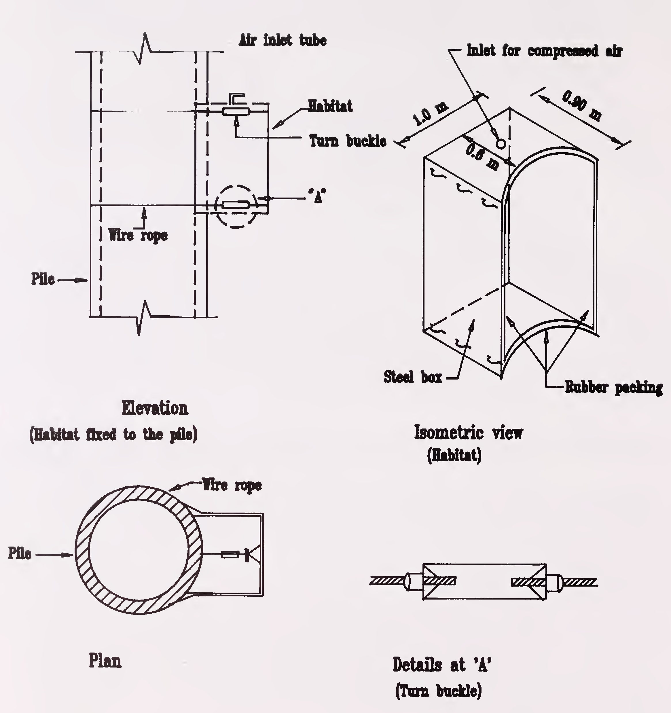
Pig. 5.2 Typical habitat for under-water repairs48
(iv) Strengthening of Arch Rings : The arch ring can be strengthened in two ways - by adding material to the intrados or to the extrados. Adding to the intrados causes the least disturbance but is more difficult to complete successfully. Also it results in a reduction in headroom or clearance which is often restricted and will, in most cases be the cause of new damage to the intrados as experienced on many bridges even where the headroom/clearance satisfies legal limits. Extra material may be placed by shuttering and pumping concrete (which is difficult to compact at the crown) or by fixing a mesh to the intrados and spraying concrete. In both cases, any shrinkage of the new concrete will tend to make the old and the new material separate radially. Also these impervious rings prevent natural drainage between the stones or brick work of the arch so that special provision must be made to deal with water or under severe climatic conditions,such as inmountainous regions, with ice. Sprayed-on concrete will in any case change the appearance of an arch constructed of stone, brick or a combination of the two.
A more effective, but at times a more expensive, treatment is to remove the fill and cast the extra required thickness on the extrados of the arch. Usually, a full ring is cast but occasionally only the end quarters are strengthened to act as cantilevers and reduce the effective span of the arch. Normal concrete placing techniques are satisfactory. Replacement backfill may be with normal or lightweight concrete. The latter will reduce dead load on the foundations but may also reduce the factor of safety for stability of the substructure.
Another expedient which is satisfactory where the increase in load carrying capacity is relatively small, especially for small span bridges, is to cast slab at road level to act as an auxiliary deck which spreads the wheel loads.
For cracks in arches, grouting with cement, at pressure 4 to 6 Kg/Sq.cm is sometimes quite effective, though care should be taken to see that pressure will not damage the surrounding masonry.49
Since the majority of bridge structures will be of concrete, RCC as well as Prestressed Concrete, the techniques are described in a separate Chapter VI.
Comparatively very few defects have been reported with well designed and fabricated shear connectors. Problems with concrete decks in composite structures are essentially of the same kind and order of magnitude as those found in concrete decks in regular structure. It is likely that some early structures are seriously inadequate with regard to shear connectors for the heavier design loads now specified. The same can be also said for the main load carrying structural steel components.
Difficulties may be encountered with deck replacement or even major deck rehabilitation and strengthening operations in those composite bridges in which residual relieving stresses have been introduced by sophisticated erection procedures combined with an elaborate casting sequence for the bridge deck. Such cases would be very few in this country.
In reconstructing deck slabs, use of very high pressure water jetting say 10,000 psi, to remove the concrete around shear connectors is considered preferable to jack hammers so as to minimise damage.
Many of the old bridges (usually truss or arch bridges)have either warped steel plates with a bituminous surfacing or a concrete deck. Due to insufficient waterproofing the steel plates are often corroded.
Bridge decks can be replaced by new concrete decks or by new orthotropic steel decks, though these have not been used in India so far. Usually,when a reduction in dead load or additional widening (adding cycle or pedestrian lanes) are necessary, replacement by an orthotropic steel deck is preferred. Bolting is the preferred method of connecting the new deck system to existing structural members.
Depending on the type of bridge and the load carrying capacity of its structural components, the new concrete deck is placed as a non-composite50
element, as a partially composite element (e.g. in composite action with the stringer and/or cross beams) or as a totally composite element (i.e. in composite action with all main load carrying elements).
The use of light weight concrete is often preferred in such cases where reduction in dead load is an important factor. Sometimes to save weight, a type of steel grid decking is used where the grids can be either left open or filled with concrete.
Strengthening usually involves more conventional techniques such as installing new diaphragms to existing double compression members (increasing buckling strength), strengthening or replacement of diagonals. Plate girders may be strengthened by external prestressing cables, anchored and fixed on the web in the required parabolic curvature acting in a similar way as in prestressed concrete.
Strengthening is sometimes concerned with compression failure and has involved the addition of stiffeners to flanges, webs, and diaphragms.
Cracks can be due to any one or a combination of the following reasons :
Crack repair methods depend on the root cause of crack initiation. The structure and especially those components which influence the overall safety of the structure should be analysed.51
Repairs can be made by techniques such as drilling holes at the crack tip (this should only be done in less sensitive locations), cutting out the cracked material and bolting plates in place, cutting out the crack and rewelding with a higher class weld (e.g. increasing the size and penetration of a fillet weld),52
strengthening the connection by introducing stiffening and by changing the structural action so that loads are supported in a way that prevents high stress range from developing.
Arc welding has become an accepted procedure in underwater construction, salvage and repair operation. Underwater welds made on mild steel plate under test conditions carried out in developed countries, have consistently developed over 80 per cent of the tensile strength and 50 per cent of the ductility of similar welds made in air. The reduction in ductility is caused by hardening due to drastic quenching action of the surrounding water. Structural-quality welds have been produced by means of special equipment and procedures that create small, dry atmosphere in which the welding is performed. However, this process is expensive.
Gas welding under water is not considered to be a feasible procedure.
A word of warning appears appropriate. Although arc welding and gas cutting are now common underwater techniques, electric shock is an ever present hazard. This hazard can only be minimised through the careful application of established procedures.
This can be used to strengthen old truss bridges. The strengthening scheme consists of superimposed arches, hangars and additional floor beams. The concept of combining a truss with an arch is by no means a new system. The idea is that a light arch can carry a significant load if properly supported laterally. In this case, the truss with its cross-beams provides the lateral support while the arch in combination with the hangars and additional floor beams provides the increased load carrying capacity. Additional floor beams and hangars are used for two reasons :
The scheme of strengthening by a steel arch superposition is illustrated in Fig. 5.3.53

Fig.5.3 Steel arch superimposition to strengthen old truss bridge
The thrust of the arch can be resisted by one of the following means:
The arch superposition scheme can be considered as an overall strengthening measure. The load carrying capacity of the entire structure is upgraded, thus allowing the live load to be increased. There is no need for temporary shoring or jacking for the installation of the superpositioned elements. The increase in dead load can be expected to be in the order of approximately 15 per cent to 20 per cent. The slender arch contributes only modest amounts of additional stiffness to the truss.
These can be overcome by suitable structural alterations and increased damping for which a specialist in dynamic behaviour of structures may have to be consulted.54
Except for giving treatment to wood, there are no special techniques for repairs of timber structures. The distressed members could be either replaced or strengthened with steel plates.
Table 5.1 gives a summary of some typical items of repairs for some problems. Appendix ‘2’ is a summary of commonly employed techniques and materials for components of bridges of various types and distresses.
It may be categorised as below :
The details are given in subsequent para :
In all cases where concrete surfaces are repaired, the condition of the existing concrete in the exposed damaged area is of primary importance in the durability of the repair. The latter can be seriously compromised if there is a poor adhesion between the fresh concrete of the repair and the existing concrete surface. Therefore, it is important that the contact surface is in sound concrete and that all foreign materials are removed that might affect or otherwise impair the repair. In general, damaged and fractured concrete must be removed to a sound surface which must be properly treated and for this several methods are available :
The choice of a suitable method depends on the situation, especially on the extent and thickness of the layer which has to be removed, as well as on the type, location and position of the damage in the structure. The thermal and chemical methods are rarely used and are restricted to special circumstances and hence have not been described here.
(i) Mechanical Methods
In general, Mechanical equipment is preferable, as it is more intensive, reliable and speedy. When choosing and applying mechanical methods, it must be ensured that the sound concrete and the reinforcement are not damaged by them. If necessary, trials should be carried out under realistic circumstances. During a mechanical removal of concrete,dust will always occur. However, the surface must be made free of dust on completion of the work. Normally used methods are milling, chipping, sand blasting, water or steam blasting and compressed air cleaning.
(ii) Hydraulic Methods
Hydraulic methods such as use of water jetting are also in use and are considered preferable to jack hammers for preventing damage. A water jet with 10 to 40 MPa pressure at the jet will remove loose particles, scaled concrete or remove vegetation coatings. This method is not applicable for roughening of solid concrete surface. In high pressure water-jet method, the pressure at the jet is 40 to 120 MPa. This is most efficient for removal of soft areas of the concrete surface. In hydro-jet method, the jet pressure is kept at 140 to 240 MPa. In this, the water-jet is capable of a deep penetration into the concrete or even cutting grooves in it. Such high pressure water-jets need careful handling or else things could be hazardous. This method is essentially free of vibrations, but there will be deep penetration of moisture into the concrete.56
(a) General
Bonding agents are recommended to improve the bond between old concrete and the new repair concrete. There are two different types of bond mechanisms:
In most cases, both types of bonding exist in combination. There are several types of bonding agents explained in the following paragraphs.
(b) Cement paste
This bonding agent consists of a cement paste with a low water/cement ratio which is brushed into the surface to be repaired.
(c) Cement slurry
Another bonding agent is cement mortar, which can be of high or low viscosity, consisting of equal parts of cement and sand along with water. It can, however, also consist of the repair mortar itself, from which the coarse aggregate has been removed.
(d) Bonding systems of polymer modified cement
Generally, in these systems, the polymer is mixed into the cement paste or cement mortar via the mixing water. Dispersions free of plasticizers with certain portions of solid substances such as vinyl-propionate-copolymers or acrylic resin dispersions or poly- vinylacetate-dispersions may be added to the mix. In some instances, emulsions may be used. The effect depends on the type of resin being used. These additives are often used not only to improve the bond strength, but also to improve the workability and water retention capacity.57
(e) Resins
There are two basic types of bonding agents made of two component resins: emulsifiable agents and normal agents. The first case consists of a combination of a water emulsifiable epoxy resin, a polyamide resin hardener and a filling material. The epoxy resin and the hardener are initially mixed together before placement. Filler may be permitted in a suitable designed ratio. If required, the mixture may be diluted with water. In the two component resin bonding agents, a pure resin-hardener-mixture is used, with or without fillers. Resins with filling materials are used in practice for the following reasons :
In the latter case, the influence of possible heat development should be considered.
While considering the epoxy resin as bonding agent, it is essential to investigate the following aspects :-
(f) Evaluation and limitations :
At this stage of development, the evaluation of the use of bonding agents with regard to their effectiveness and durability is still very difficult. There is doubt as to whether positive properties, presented in various publications, are valid under conditions occuring in practice. Strengths of some bonding agents are reported to vary, under influence of water or some other factors also. Also, long term tests have shown much less strength of some bonding agents, than with short term tests.
There does not exist, within the current state-of-the-art, any promising method of transforming penetrated chlorides into insoluble compounds so as to passivate a potential for corrosion. Current possible methods (Not yet Introduced in India) of chloride removal are as follows :
It should be pointed out that the efficiency of the first three methods has not yet been proven, but ongoing research and tests may provide answers in the future.
A concrete surface exposed to climatic effects will change its structure and physical appearance with time. Therefore, the durability of a structural element cannot be assessed only from the physical appearance of its surface.
Due to the techniques used during construction, the composition of the surface layers of the concrete are different from the interior of the structural element, in particular the cement content increases towards the surface. The59
concrete surface itself is formed by a "cement film". It has no aggregates and depending on external influences, can be eroded. In addition, when these boundary layers are removed for aesthetic or visual reasons, changes due to climatic effects at the uncovered surfaces are to be expected in the course of time. However, alterations to the concrete surface, for desired aesthetical reasons to improve appearance, need not affect the durability of the structural element. If the concrete is of a proper composition.
If the concrete composition does not correspond to the external influences and further development of an already existing weathering is of concern, measures need to be taken to minimise or stop this process.
In both cases, the following surface protection measures can be used:
The protection provided by these measures increases in the order given above.
The difference exists in how protection is achieved between impregnation systems and sealers and/or coating systems. Protection is achieved in the impregnation system through a prevention of a capillary absorption of water by the concrete. Depending on the material used, this effect will be achieved by a hydrophobation of the pores at the walls or by a narrowing of the capillary ducts, which result from a film formation on these walls. Sealers or coatings lead to a closed thin film on the surface.
(a) Impregnations, hydrophobations :
The materials used for impregnations are:
(i) Silicon organic impregnation materials are :
(ii) Resins :
In contrast to the silicon organic impregnation materials, the protection provided by the resins is mainly derived from a film formation on the surface of the pores and a narrowing of the capillaries. Types of materials used are:
(iii) Oils :
Low molecular, organic compounds in the form of oils may be used for impregnation. Most experience available is that associated with linseed oil. Linseed oil may be used in the following forms :
(iv)Technique of application :
(a) The efficiency of an impregnation basically depends on the preparation of the surface and on the required depth of impregnation. Requirements for impregnation material are small molecular size and low viscosity. The absorption is accomplished via the capillary voids of the concrete. The proportion of capillary voids increases with increasing water/cement ratio. The impregnation liquid must be placed on the concrete surface in an amount to fill the voids. The application may be accomplished by means of a brush, lambskin roller or by spraying. Depending on the absorptive capacity of the surface, several repetitions may be necessary. For solvent containing61
impregnation systems, the concentration of the solution during the first application may require thinning to achieve a deeper penetration. Penetration depth is especially important where traffic wear is expected. Therefore, impregnation protection systems are only suitable where the concrete surface will not be removed by abrasion, damaged or locally disturbed by the formation of cracks.
While impregnation with resins may be successfully used on horizontal surfaces, hydrophobizing impregnations are not suitable for horizontal surfaces where water will stay on the surface. Therefore, the primary field of application of hydrophobizing impregnations is on vertical or sloped surfaces, where the water can flow off easily.
(b) Sealers : In contrast to impregnations, a sealer forms a film on the concrete surface. This can be achieved by increasing the applied quantity of an impregnation agent, which tends to form a film, or through the choice of suitable resins. The following plastics are commonly used :
Sealers can also serve as a primer for coatings :
(c) Coatings : Coatings as compared to sealers provide an additional protection against mechanical influence. Consideration should also be given to the fact that coatings, as compared to sealers, have an increased resistance to the diffusion of internal moisture. A differentiation should be made between thin and thick coatings. Thin coatings, will follow the contour of any unevenness of the surface. Thick coatings should form as much as possible a plain surface with a thickness of 1mm or larger. Therefore, a thick coating will smooth out any unevenness of the surface.
Requirements of coating materials are as follows :
Plastic modified cement systems and resins are suitable for coatings. Thick coating of resin mortars, upto thickness of 3mm can be produced by repeated wet-in-wet application of thin layers. Other coatings suitable for protection at concrete surfaces are epoxy resin, bituminous compound linseed oil, silicon preparation, rubber emulsion or even mere cement coating.
Coatings should also have the capability to bridge cracks. This requires a high elasticity of the coating material. The epoxy systems are known to change their properties with variations in temperature and exposure to sunrays. For thinner layers bridging of cracks can only be achieved when a limited debonding of the coating adjacent to the crack is possible. With such coatings, it is possible to bridge cracks upto 0.2mm in width. Bridging of larger crack widths can be achieved by the insertion of a fibre material into the coating, e.g. in the form of textile fabrics. Recently, two component liquid sealers have been developed which can be sprayed onto the concrete surface. They have the ability to bridge larger cracks as a result of their low modulus of elasticity and their improved elongation. Some systems, however, are not sufficiently resistant to mechanical effects and weathering influences (mostly UV-rays) and they may require an additional protection layer. They may also be used as a membrane underneath asphalt overlays.
If the deterioration process has reached a level where a shallow surface repair is not desirable, a replacement of the missing concrete section should be considered. The technical choice of the repair material depends on volume to be replaced, the depth of the repair, the loading effects to be expected and the conditions of application on site. In all cases, an appropriate pre-treatment of surface is required.
The various measures for damage repair may, in addition, require surface protection measures to provide for the durability of the repair.63
The following materials for the replacement of a substantial depth loss of the concrete surface should be considered :
Shotcrete (gunite):
Shotcrete is suitable for the repair of surface damages, concrete replacement and for the strengthening of structural elements.
Pre-treatment of the surface is of prime importance when using shotcrete. Sand blasting has proved to be an efficient surface treatment procedure. However, environmental protection regulations should be verified before use. The surface should be sufficiently pre- moistened. No bonding agent is necessary because at the interface surface, a mortar enrichment occurs as a result of aggregate rebound.
Shotcreting in multiple layers requires that the preceding layer achieves a sufficient degree of hardness. Minimum reinforcement may be required for thicknesses larger than 50mm. This reinforcement should be fixed in position in such a manner that it remains stiff and keeps its positon during shotcreting operations and to ensure adequate cover in the finished works.
Curing may be accomplished by an evaporation protection, e.g. plastic sheet, to prevent a rapid drying out. If a freeze- thaw/salt resistant concrete is required, air entrainment admixtures may have to be added to the concrete mix. Also, surface protection measures may become necessary.
There are two basic shotcrete processes :
Shotcrete suitable for normal construction requirements can be produced by either process. However, differences in cost of equipment,64
maintenance and operational features may make one or the other more attractive for a particular application.
Properly applied shotcrete is a structurally adequate and durable material and is capable of excellent bond with concrete, masonry, steel and some other materials. However, these favourable properties are contingent on proper planning, supervision, skill and continuous attention by the application crew.
In general, the in-place physical properties of sound shotcrete are comparable to those of conventional mortar or concrete having the same composition.
Special variants of shotcretes result form the addition of fibre or of synthetic resins. Steel, glass (boron- silicate-glass) and plastics are used for the fibres. The ratio of the fibre to cement will be larger in the initial mixture than in the rebound material. In the case of steel fibres, corrosion protections must be considered, unless the fibres are protected from corrosion. The last layer must not contain steel fibres.
Removal and Replacement of Concrete :
This is considered necessary when the concrete is found to be delaminated by sounding with hammer or chloride ion content is critical or micro cracks are found on a chipped surface or concrete is carbonated upto reinforcement. The removal of damaged concrete is usually done with electrically powered or compressed air ensuring that the reinforcement is not damaged. Rat chisel is normally used to minimise micro crack formation which can cause repair failures. For a complete removal of a structural element larger equipment such as sawing, cracking, thermal lancing and blasting may also be adopted. Special care needs to be taken while removing concrete in prestressed concrete structures. Hydro demolition is the latest method where water is sprayed on to the concrete in thin jets at a very high pressure and enables removing of concrete in a more efficient and precise manner without damaging reinforcement and in a better working environment.
The replacement of concrete in larger continuous areas should proceed in the same manner as during the construction of the concrete structure. However, certain features resulting from the combination of old and new concrete should be considered.65
Placing concrete in the area to be repaired should be accomplished in such a manner as not to impede concrete flow and to avoid the entrapment of air, thus avoiding voids in the concrete. Therefore, the formwork must be sufficiently rigid and tightly fitted to the existing concrete in a manner to minimize leakage of cement paste. The surface of the existing concrete will require adequate preparation, careful cleaning and pre- moistening.
The replacement concrete should have final properties that match the existing concrete as closely as possible (strength, modulus of elasticity, creep co-efficient, etc.) To avoid temperature and shrinkage cracks, especially in the transition area, the type of cement, cement content and the water/cement ratio should be carefully evaluated.
The use of plasticizers is recommended. Recompaction/revibration may be required to improve the contact to the old concrete, however, care should be exercised to avoid a retempering of concrete after an initial set. Trial repairs on non-critical structures are essential before the main work is undertaken.
For larger concrete volumes, minimizing the temperature difference between old and new concrete may require special procedure (cooling of new concrete and/or heating of old concrete). Type and duration of curing should be evaluated on a case by case basis.
Before deciding the most appropriate
methods/material for repairing/sealing cracks a determination should be made on the cause of the cracks and whether they are active or dormant. Crack activity (propagation or breathing) may be determined by periodic observations with Demec or other movement gauges, optical crack gauges, fitter gauges or tell tales. A classification of cracks in accordance with its primary cause is given in the FIP Guide to Good Practice "Inspection and Maintenance for Concrete Structures". The repairs techniques generally applicable for the various types of damages, particularly in case of deterioration of concrete are as follows :
| (a) | Active cracks | : | Caulking, jacketing, stitching, stressing, injection.66 |
| (b) | Dormant cracks | : | Caulking, coatings, dry pack, grouting, jacketing, concrete replacement, penumatically applied mortar, thin resurfacing. |
| (c) | Crazing | : | Grinding, coatings, sand blasting, pneumatically applied mortar. |
| (d) | Alkali aggregate | : | Injection, concrete replacement, total replacement. |
| (e) | Holes & honey | : | Total replacement, combing pneumatically applied mortar, prepacked concrete, replacement. |
| (f) | Cavitation | : | Coatings, pneumatically applied mortar, concrete replacement, jacketing. |
| (g) | Excessive Permeability | : | Coatings, jacketing, pneumatically applied mortar, prepacked concrete, total replacement, grouting. |
Repair of cracks becomes necessary when :
It is always desirable to attempt repairs to cracks at as early a stage as possible.
Basically, a crack resulting from one time load application and which has ceased to propagate can be repaired by pressure injection with epoxy resins67
such that stability is restored and any adverse influence on the life expectancy of the structure is eliminated or minimized.
In the case of cracks which are the result of time-dependent constraints such as shrinkage or settlement, the repair should be delayed as much as possible, compatible with the use of the structure, such that the effect of further deformation is minimized. Pressure (not too high to cause damage) injection of epoxy/cement can still be effective even for an active crack (a cyclic opening and closing resulting from temperature changes or cyclic loading) where the objective is primarily corrosion protection of the reinforcement. However, if the crack is of a nature to adversely effect the structural integrity of the structure strengthening will be required prior to crack repair.
The material used for crack repair must be such as to penetrate easily into the crack and provide a durable adhesion to the crack surfaces. The larger the modulus of elasticity of the material, the greater will be the obtainable adhesion strength. The interface of the material and the crack surfaces should be such as not to allow infiltration of water and to resist all physical and chemical attacks. Currently, the following fluid resins are used for crack injection :
The formulation of commercially available injection resins vary widely in their properties, therefore, care must be exercised in making the proper selection. Important properties of any injection resin is its resistance to moisture penetration and alkaline attack from the cement. Where tensile strength is a requirement, the tensile strength of the resin should approach that of the concrete as closely as possible. Therefore, a stiff and highly adhesive resin is desirable. These properties are available in epoxy or unsaturated polyester resins. After hardening of the injection material, the "stiffness" of the crack will be dependent upon the elasticity of the resin.
A polyurethane or acrylic resin is recommended where moisture resistance is a requirement. Epoxy based low viscous resins will penetrate to68
the crack root where the crack width at the surface is larger than 0.1mm. Comparable results are obtainable from unsaturated polyester and polyurethane resins. Acrylic resins are capable of sealing fine cracks because of their low viscosity. However, in all cases, this requirement can only be obtained with an appropriately long reaction time. Fast reactive systems will only close the crack at its surface.
Although cement paste is relatively inexpensive, its use is limited to crack widths of approximately 3mm or larger because of their limited viscosity. However fine ground cements allow injection of cracks with widths down to 0.3mm. Cement glues and mortars are of importance in such applications as injection of voids (honeycombing), sealing of ducts, etc. For these applications the use of appropriate additives are recommended to improve viscosity and reduce the tendency for settlement. Improvement of workability will be obtained if the cement suspension is introduced into the mix with high speed mixers.
As a rule, the following steps are necessary during injection :
(i) Packer
Packers are auxiliary means by which the injection material is injected into the crack. Depending on the method of installation, they may be classified as an adhesive packer, drilling packer or a jet- packer.
Adhesive packers are pasted into the crack. The hose to the injection device is connected to the nozzle of the adhesive packer. In the case of drilling packers, holes are drilled in the plane of the crack or may be inclined to the crack plane. The packer consists of a threaded metal tube which is encased in69
a rubber like sleeve and equipped with a nut. After insertion into the drill hole, the rubber sleeve is compressed by screwing down the nut. In this manner, the drill hole is sealed. A nipple, equipped with a ball valve to which the injection hose is attached, is screwed into the packer opening. The valve opens itself when subjected to the injection pressure.
(ii) Injection equipments
Injection equipments are differentiated as one- component or two-component equipments. In the case of one-component equipment, the resin is mixed first and subsequently injected into the crack. Typical representative one-component equipments are a hand grease gun, treadle press, air-pressure tank, high-pressure tank and a hose pump. With these equipments, rather high pressures can be applied. However, the influence of the applied pressure on the packer, the tamping and the crack itself should be considered. The pot life of the material is an important parameter in the application of one-component equipments. Therefore, the length of crack that can be injected is subject to the volume of material being used and its pot life.
In the case of two-component equipments, resin and hardener are separately transported to the mixing head by means of fully automatic dispensing equipment. Therefore, pot life is only of secondary importance. Errors in mixing two-component resins can have significant effect on the hardening of the resin. Therefore, the use of pre-packaged batches prepared by the manufacturer is recommended. Generally, in the case of two-component automatic dosing devices errors will not be discovered in sufficient time to apply corrective measures.
(iii) Injection
A distinction must be made between low-pressure injection (upto approximately 2.0 MPa) and high pressure injection (upto 30 MPa). The penetration speed of the injection resin does not increase proportionately with increasing pressure. The viscosity of the resin strongly influences the rate of injection, especially for small crack widths and in the area of the crack root.
The injection of a crack is completed when either the resin or hardener has been consumed from either of the containers or a back pressure has built up in such a manner that no further material can be injected into the crack.
For the low pressure process, the resin has a relatively greater amount of time to penetrate gently into the crack. Because the injected resin may flow70
from the main crack into fine capillaries, a post-injection procedure may become necessary. This will be especially true for high- pressure injection. Therefore, it must be accomplished prior to hardening of the previously injected resin.
Row capacity and hardening reaction of the resin is dependent on temperature. This factor must be considered for cold structural elements and for declining ambient temperatures. High resin temperatures shorten the processing time in one- component equipments. For crack widths up to 0.2mm, a thick sealing at the cracked surface with a resin is usually sufficient. It will be absorbed by capillary action in the crack. For epoxy injection of cracks see Fig.6.1.
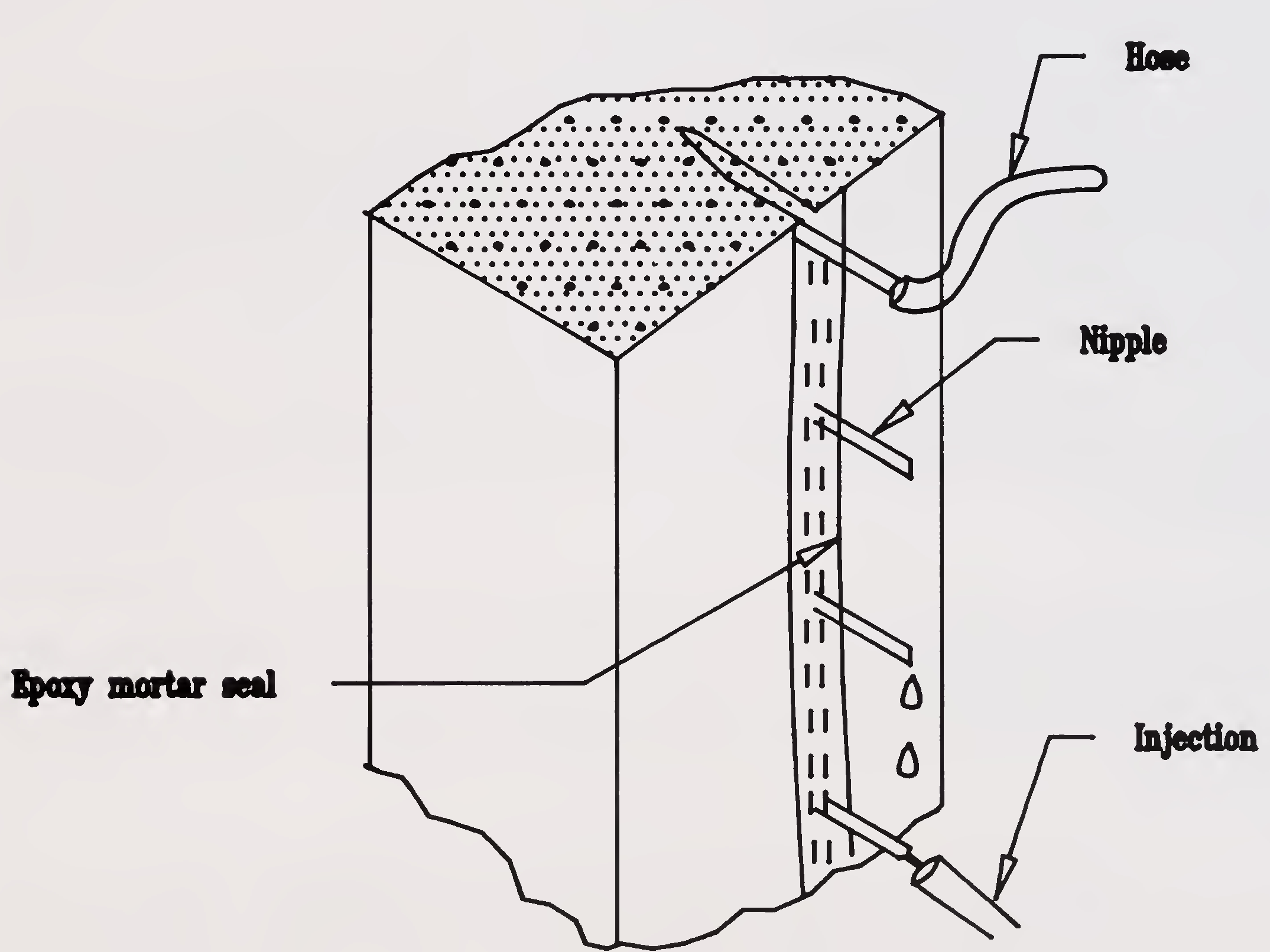
Fig.6.1 Epoxy injection of cracks71
The usual testing methods are drill core removal and ultrasonic testing. In special cases, efficiency can be determined by measurement of steel extension or the deformation of the structural element before and after injection under selected test loads or by determining the influence line.
(i) Coring
The success of an injection operation can be determined by a relatively simple procedure of removing cores taken through the crack plane. Because of the unavoidable damage to the structural element such evaluations should only be used in exceptional cases. However, they are meaningful as preparatory evaluation, e.g. determining crack depth.
(ii) Ultrasonics
With ultrasonic measuring, the efficiency of the groutng operation can only be evaluated when the propagation of sound is oriented approximately normal to the crack surface. It is recommended that during ultrasonic testing, data be gathered not only with regard to the elapsed time for the sound to pass through the member, but also to variations in sound intensity.
The measurement with the existing equipments and methods is however not easy to be carried out and the results cannot be interpreted yet reliably.
Adequate materials, equipment and experience of the operating personnel are a essential requirement for the successful injection of cracks. Appropriate certification is necessary to determine the qualifications of operating personnel.
A system of quality control of the resin should be implemented to guarantee a consistent quality for each new application. These are : the determination of the infrared composition (IR- Spectrum), the pot life, the viscosity, the density, the glass transition temperature as well as the development of the tensile strength during hardening and the hardened material. To avoid such expensive routine controls,some resin manufacturers have contracted with independent institutions to provide testing on a statistical sampling basis as a monitoring control. After successful testing,the resin batches are provided with a stamp of the testing institute as well as with information regarding durability. Stringent regulations for the use of resins72
crack repair, especially where they must resist tensile stresses, is required to insure the behaviour of structural elements and to avoid additional damage that might be caused by the utilization of inadequate materials and procedures. Studies have shown that injection with epoxy resins can be successfully accomplished.
No reliable data or appropriate evaluations are currently available for polyurethane and acrylic resins, that might be used as a crack repair material. This partially results from clients requiring epoxy resins even when other resins might be more appropriate.
A reduction of adhesive strength will occur when the concrete surface of a crack is excessively moist. There is also a risk of a reduction in the quality of epoxy resins when they are used for the repair of structural elements at extreme temperatures. Current experience indicates that epoxy resins can be succesfully utilized when the temperature of the structural element is not less than 8°C. Because of the lack of experience with other resins (e.g. PUR) the 8°C limit should be maintained. Acrylic resins are an exception, they harden at temperatures below the freezing point.
For relatively hot structural elements, as compared to normal temperatures, a considerable reduction in the workability time of the resins may result. In these cases, the temperature of the structural element in relation to its influence on the pot life should be considered and previous testing may be appropriate.
In many cases, only one side of the structural element to be injected is economically accessible. Experience has shown that one-sided injection of a through crack in a large structural element or deep cracks are not always uniformly filled.
An effective epoxy resin injection can still be accomplished when there is a cyclic width variation, as a result of traffic loading, during injection and hardening, provided this variation does not exceed 0.05mm. Appropriate traffic limitations, upto maximum of the first three days depending on temperature should be implemented if larger cyclic crackwidth variations are anticipated. In the case of large crack width, variations resulting from temperature injection should be co-ordinated such that hardening commences at maximum crackwidth opening. Thus, the filled crack will be subjected to a compressive stress, atleast for temperature variations. Experience indicates73
that there is no difference in behaviour between an alkaline or carbonized concrete.
The deformability of the resin, as a rule, is not sufficient to close active cracks tightly and durably in case these movements cannot be stopped. Under these circumstances the feasibility of expanding the crack and forming a permanent expansion joint should be explored.
Other methods are :
(a) Stitching - Stitching across the cracks by in-situ reinforced concrete is done either along the cracks or as a series of bands around the members. Reinforcement is placed across the cracks in suitable grooves which are suitably packed with wet concrete gunited. Alternatively, if geometry permits, bars grouted in holes could be used for stitching.
(b) Jacketing : This involves fastening of external material over the concrete to provide the required performance characteristics and restoring the structural value. The jacketing materials are secured to concrete by means of bolts and adhesives or by bond with existing concrete. Fibre glass reinforced plastics, ferrocement and polypropelyne can also be used for jacketing.
For PSC members, the simple methods adopted are sealing and coating to fill out the cracks, grouting of cracks, repairing corrosion locations, and vacuum grouting using specially formulated resins to fill voids in the ducts. Some of the latest techniques include use of special chemical material formulations to satisfy the requirements like high tensile strength, special thermal properties etc. Some of the methods are common to those for RCC and the relevant details given earlier may be referred..
The embedment of reinforcing steel in concrete normally provides adequate corrosion protection due to the alkalinity of the concrete surrounding the steel. Because of its alkalinity, concrete forms a passivating film on the surface of the encapsulated steel as a result of the presence of a saturated lime74
solution in the cement gel. Moist concrete typically has a pH value in excess of 12 which maintains the passivating film. This film is however de-passivated when the pH level is reduced below a value of approximately 10 to 11, or when a sufficiently high chloride concentration of about 0.4% chloride by weight of cement is present.
In case the alkaline passivation film is destroyed or carbonization has reached the reinforcement or if moisture and oxygen are present, corrosion of the reinforcement will occur. In the absence of moisture (i.e. dry concrete) the corrosion process is inhibited, even if the concrete is carbonated, wetting and drying cycles increase corrosion.
When reinforcement corrodes to a certain extent, the surrounding concrete cover tends to crack and spall or split. The cracks are caused by internal bursting stresses developing in the concrete as a result of a net increase in volume by the formation of corrosion products. Spalling of the concrete cover will then permit the entry of water and other corrosion accelerating agents and the rate of corrosion accelerates. Non-expansive black rust associated with severe pitting and rapid corrosion can occur in low oxygen wet high chloride conditions in salted bridge decks, substructure and marine structures.
N.B. When the deterioration is localised in steel it is worth repairing it. But once overall deterioration sets in, it is better to replace or strengthen when safety is at risk.
(i) Preparation prior to protection
The decision on the necessity of removal of chloride contaminated concrete cover, where commencement of the corrosion process is imminent, will depend upon the amount of chloride content, availability of moisture and degree of carbonation. This decision requires a case by case evaluation. If the corrosion protection of the reinforcing steel requires removal, the reinforcement will have to be exposed completely.
The removal of rust from the uncovered reinforcing steel is generally accomplished by sand-blasting devices, needle hammer and wire brushing. The removal of rust from the remote side of the bar is a difficult operation. A careful check and a repeated treatment of the individual bars is essential.75
(ii) Restoration of the protection
A corrosion protection should be applied to the cleaned reinforcement prior to restoration of the concrete cover. If possible, the reinforcing bar should be encapsulated in an alkaline coating. i.e. cementatious bond coat. This can be achieved best by a cement-bond repair mortar. In addition, measures have to be implemented such that this active corrosion protection will not be compromised again by carbonization, spalling or by corrosive agents reaching the level of the reinforcement.
The restoration of the corrosion protection system of the reinforcing steel can be accomplished by the following means :
The choice of the system depends on the thickness of concrete cover. Concrete or cement mortar can be used if the concrete cover can be achieved in accordance with appropriate regulations. In cases where less than adequate thickness of cover is obtainable, polymer modified materials give adequate resistance. The Central Electro Chemical Research Institute (CECRI) at Karaikudi has developed a process for protecting the rebars from corrosion and the same has been described in IS 9077-1979. The Director, CECRI, Karaikudi could be approached for more details. Development of fusion bonded epoxy coated reinforcement is also in progress.
(iii) Preventive corrosion protection
In the case where concrete cover is thin it may be desirable to seal the surface with an epoxy resin and solvent containing acrylic resins to prevent carbonization or corrosion.
(iv) Cathodic protection
The cathodic protection (CP) technique has been adopted in developed countries to protect steel pipe lines and tanks from corrosion. In recent years it has been applied experimentally for the protection of reinforcing steel in concrete.76
Corrosion of steel in concrete proceeds by the formation of an electro-chemical cell. With the concrete acting as coupling electrolyte, an anodic reaction occurs at some points on the steel surface and cathodic reactions consume the dissolved electrons on the remaining portion of the steel surface.
The presence of chloride ions will produce a local de- passivation. By means of an externally applied small direct current (DC) the electric potential between the steel and concrete is shifted to a non-critical level. Thus, the electrons impressed in the steel force the steel to act as a cathode in the electro-chemical cell. The potential shift produced by the DC is critical to the cathodic protection. Because of the high resistivity of the electrolyte concrete, a uniform distribution of the protection current throughout the structure is necessary. But difficulties in achieving this and high costs have prevented cathodic protection being widely used in bridge decks and superstructures. However, research continues.
It is accepted that there is still research required to be done before cathodic protection can be safely applied to prestressing steel. (Table 6.1)
This section deals only with the possible repair of protection to prestressed reinforcement. It should, however be noted that the repair of the concrete and the normal reinforcement of a prestressed concrete structure will also require attention. In most cases, the prestressing force is still active and the stresses transferred to the concrete must be carefully considered, especially when repairing concrete in the anchorage zones.
Repair of the corrosion protection systems for bonded tendons
In the case of bonded tendons, the prestressing steel should be protected by the concrete cover and the cement grout in the ducts.
(a) Vacuum-procedure
Where the ducts are not completely filled with cement grout, subsequent grouting is necessary. This can be accomplished by vacuum grouting techniques. The advantage of this procedure is that the regrouting of a duct requires only one drilled hole for each void. Such holes may be pre-existing in the form of the drilled holes used for tendon inspection or for obtaining samples for chloride content evaluation. Only a diameter adjustment77
| Rehabilitation Method | Advantage | Disadvantages |
|---|---|---|
| Concrete Overlay | Structural component of deck slab. Relatively impermeable. Relatively long service life. Well-suited to repair of badly spalled or scaled decks. Increases cover to reinforcing steel. | Less suited to decks with complex geometry. Cannot bridge active cracks. Extra dead load will result. Difficult to provide adequate texture on low-slump concrete surface. Unlikely to stop active corrosion. |
| Water-proofing membrane with bituminous concrete wearing course | Bridges active cracks Relatively impermeable. Provides good riding surface. Applicable to any deck geometry. Many qualified contractors | Performance highly variable. Will not stop active corrosion. Not suited to rough deck surfaces. Service-life limited by wearing course. Non-structural component of deck slab. Not recommended for grades in excess of 4% where heavy vehicles make turning or braking manoeuvres. Could be substantially expensive. |
| Cathodic protection | Can stop active corrosion in top mat of deck rebar only. Can be used on decks with active cracks. Provides good riding surface. Applicable to any deck geometry. | Presence of wearing course without water-proofing may accelerate deterioration of the concrete. Non-structural component of the deck slab. Periodic monitoring required. Service life limited by wearing course. Specialized contractor and inspection required. Electrical Power source required. It is expensive. There is some concern about protection by Cathodic protection as there might be some risk of failure by hydrogen embrittlement. |
may be required. A comparison between the assessed volume of the void and the amount of grout consumed will provide a control measure as to the success of the operation. Where discrepancies occur further borings will be required. A careful drilling procedure is required to avoid damaging of the prestressing steel. Special devices and techniques have been developed for this purpose, such as : slow drilling speed, special drill head, small impact force, drilling without flushing, sucking away of drilling dust and automatic switch off when the drill bit reaches the duct. The repair must be accomplished as quickly as possible after opening of the duct to avoid corrosion.78
After grouting, a pressure has to be applied to expel residual air from the voids. There is a risk that for large air cushions, setting water will be displaced towards defects and produce paths which will impair the corrosion protection. Therefore, mortar with low setting characteristics should be used. Special cements are available for this purpose.
In special cases, surplus water in the duct can be evacuated. However, this process requires special equipment and knowledge.
(b) Grouting of the ducts with special resins
Where ducts filled with water cannot be drained through drilling or the vacuum process and drying is not possible, the water can be displaced by use of viscous epoxy resins with a long pot life and high specific weight.
Repair of corrosion protection systems for external tendons
The prestressing steel of external tendons is protected by a tight envelope of plastic pipe or painted steel pipe and the internal void of the pipe is filled with cement grout or suitable greases. If an inspection indicates deterioration of the protection system, measures must be taken for its reestablishment. Such measures may be re-painting of steel ducts and protective caps over the anchorages, replacing of plastic pipes, tapping of local pipe damage, filling of voids inside the pipes etc.
Any materials used in the repair procedure must be compatible with the existing protection materials and with the prestressing steel. Some paintings, coating materials and. special grouting mortars might contain substances that can produce stress corrosion and should, therefore not be used.
There are two methods of sealing : either the porous parts of the concrete are replaced by sound, watertight concrete or the porous zones are injected with a sealing material. First, all the porous zones of the structure must be carefully removed. Then they are replaced by fully compacted concrete or mortar with a water/cement ratio not exceeding 0.4. This procedure cannot be used where there is a continuing inflow of water. In this case, sealing can be accomplished by injection.79
Strengthening of structural members can be achieved by :
The new load bearing material will usually be :
The main problem in strengthening is to achieve compatibility and a continuity in the structural behaviour between the original material/structure - and the new material/repaired structure.
It may be noted that these strengthening measures improve the strength but not necessarily the durability of the original structure.
The strengthening of structures should be designed and constructed in accordance with appropriate codes. If special codes for strengthening exist, they will of course be of assistance to the designers and contractors. However, this is seldom the case, and many problems in connection with strengthening are not dealt with in the codes. Typical problems of this kind are the transfer of shear forces between the old80
concrete and the new concrete applied for strengthening reinforcement,and the post-tensioning of the existing structure which in some respects is different from the post-tensioning of a new structure,etc.
Satisfactory interaction between existing concrete and new concrete is generally required in strengthening and repair. As a rule, the aim is to get the structural parts, composed of different concretes, to act as a homogeneously cast structural component. To achieve this, the joint between the old concrete and the new concrete must be capable of transferring shear stresses without relative movements of such a magnitude that the static behaviour is significantly affected. Furthermore, the joint must be durable for the environment in question. i.e., the composite structural component must not change its mode of action with time.
When using large concrete volumes, the possibility of additional stresses as a result of hydration heat has to be taken into account. Temperature differences can be limited by special measures, e.g., pre-heating of the old structural element and/or cooling of the fresh concrete.
Differences in creep and shrinkage properties between old and new structural elements will require careful evaluation. Cracks may develop as a result of potential increases in constraint forces. Therefore it becomes necessary to correctly detail and anchor the reinforcement. To implement the strengthening measures, it will be necessary to employ suitable mortars or concretes with low creep and shrinkage properties as well as minimal development of hydration heat. At the same time, an effort should be made to match, as closely as possible, the strength and modulus of elasticity of the new material with that of the old material. These requirements will be influenced to a large extent by the composition and treatment of the new material.
Vibrations due to traffic during hardening of the new concrete will have either negative influence or positive influence on its strength and its bond characteristics to the old concrete. This will depend on whether the vibrations are just sufficient to harden the concrete or too severe to disturb the components of hardened concrete and its bond. In case it is observed that vibrations do not have any negative influence then the traffic could be permitted in a controlled manner while the repairs are in progress. However, if the vibrations due to traffic have negative influence then stoppage of traffic or speed limits may have to be considered during the hardening phase as necessary. The critical phase may be 3 to 14 hours after making the concrete. The formwork should81
be so detailed that no relative movement occurs between old & new concrete. The reinforcement has to be sufficiently fastened so as to keep relative displacement small.
The strengthening of reinforcement subject to tensile forces can be achieved by :
In the simplest case, a strengthening of the concrete tension zone is possible by the addition of reinforcing steel. Reinforcement should be added after reducing locked up stresses to the extent possible and after the concrete cover has been removed or after recesses have been cut in the cover to accommodate the added reinforcement. Afterwards the concrete cover must be re- established. An effective anchoring of the ends of tile reinforcing steel is required. This can either be done by providing sufficient anchorage length for the steel in the concrete, or by steel plates and bolts with anchoring discs.
In special cases, severly damaged reinforcing bars must be replaced. After unloading of the structure, the damaged sections of the corroded bar can be removed and the new reinforcing bar joined to the ends of the old ones by lapped splices, welding, or coupling devices. Transverse reinforcement is needed to assure a ductile behaviour of the splice.
Staggering of lapped splices is recommended unless the distance of the bars is greater than twelve times the diameter of the bars.
Lapped splices in a structural element can produce problems (congestion, interference with the proper compaction of concrete etc.) These difficulties may be overcome by the use of welded splices or couplers.82
The strengthening of concrete structures by means of bonded plates is a technology adopted in many countries.
(a) Short-term behaviour
The load carrying capacity of this type of strengthening depends on the strength of the reinforcement, the concrete and the adhesive. At yielding of the reinforcement the adhesive will fail. Utilization of high strength reinforcement is limited by the dimensions, concrete strength, etc. Concrete strength has a large influence on the efficiency of the strengthening since the failure plane is located within the concrete.
Theoretically, higher bond stress is to be expected from an increase in the elasticity of the reinforcing element and a decrease in the elasticity of the adhesive.
Geometrical influences are primarily the dimensions of the reinforcing elements. Their length, thicknesses and widths are decisive. The length of these elements has an influence on the bond stress intensity, which decreases with length.
The bond stress will at the same time be influenced by the thickness. Therefore, glued on reinforcing elements behave differently from deformed bars which can be designed using the same permissible bond stress for all diameters. There is no proportionality between the width of the glued element and ultimate load, as an increase of width results in a reduction of bond strength. For a certain ratio of width to thickness the glued surface becomes a minimum.
With increasing width, there is a risk of defects in the adhesive. Therefore, the width of the reinforcing element should be limited to a maximum of 200mm.
The thickness of the adhesive coat, within a range of 0.5 to 5mm., has no significant influence on ultimate load. With increasing thickness of adhesive the slip between the reinforcing element and the concrete becomes greater. The concrete dimensions, according to previous tests, do not appear to have any decisive effect. The surface condition of the steel is an important parameter. Suitable conditions can be achieved by sand blasting. Oil and grease should be removed by means of an organic solvent. As cleaned surfaces corrode rapidly, a primer coating should be applied immediately. This primer serves as a corrosion protection and as an adhesive base for an epoxy resin83
adhesive. It is a specially formulated solvent containing epoxy resin. Priming with zinc dust or hot-dip galvanizing is not suitable for glued on reinforcing elements.
For the pre-treatment of the concrete surface, the procedures discussed earlier apply. Blasting with fine grained blasting materials has proven to be effective (minimum pull-off strength 1.5 N/sq.mm.). Coarse grained blasting materials will achieve a deeper roughening of the concrete surface, which results in an increased consumption of adhesive, but not necessarily in an improvement of bond strength.
(b) Long-term behaviour
The question of long term behaviour is of particular importance for these materials, the properties of which are highly time- dependent. Of considerable importance are:
(i) Creep
The creep of epoxy resin adhesives is considerably greater than for concrete. In accordance with the current state-of-the-art, it can be assumed that the creep deformation abates relatively quickly. The adhesives may have very different creep ratios. In thin adhesive layers upto 3mm the influence of creep is restricted by the cohesion of the adhesive.
(ii) Ageing
Ageing is a change of properties resulting from mechanical, physical and chemical influences; e.g. air humidity, radiation, heat, weathering and water. Ageing varies widely between various adhesives. For strengthening of metal elements, ageing reduces strength such that the long-term strength is only approximately 50% of the short-term strength. For strengthening of concrete, a more favourable relationship exists, as the adhesive coating will be loaded considerably less.84
Epoxy resin adhesives have a certain porosity, which will allow the penetration of water and other solutions. Exposure to water over long periods of time can cause epoxy resin adhesives to lose strength. Water sensitivity varies widely between various adhesives.
(iii) Fatigue strength
Preliminary tests show that the fatigue strength is approximately 50% of the short- term strength. This indicates that concrete with glued on reinforcement shows a more favourable behaviour than those for glued metal structures, for which the dynamic strength for 10 millions load cycles is only 10% of the static strength. After a dynamic load has been applied, the static ultimate strength of the concrete structure with glued on reinforcement increases. This can be explained through a reduction of the bond stress peaks as a result of dynamic load.
(c) Behaviour at failure
The slip between the reinforcing element and concrete under tensile load has an approximately linear elastic behaviour upto about half of the ultimate strength and will be influenced by the dimensions of the reinforcing element and the adhesive layer. A further increase in the load leads to a progressive increase of the relative displacement. The elastic deformations result from the deformation of the adhesive layer. This slip starts at the loaded end of the reinforcing element and moves, with increasing load, to the centre of the element. In the plastic range, a slip deformation in the concrete sub-surface also occurs. The slip in the concrete develops some millimeters below the adhesive coat. A failure occurs suddenly, by abrupt elongation of the slip interface upto the end of the reinforcing element.
In correctly designed structures with bonded plate reinforcement, a ductile failure with yielding reinforcement can be attained. Bolting on of plates to prevent pealing failures is now normally accepted in some countries.
It should however, be kept in mind that strengthening with steel plates with epoxy is a very workmanship sensitive method and so operations have to be under expert guidence only.85
(a) General
In many cases, strengthening by means of supplementary prestressing is a highly effective method. Both reinforced concrete and prestressed concrete structures can be strengthened by this method. The influence of the supplementary prestressing on serviceability and ultimate limit states can be varied within wide limits by selecting different methods of introducing the tensioning force and using different alignments of the tendon.
(b) Choice of system for supplementary prestressing :
For supplementary prestressing, so far only post- tensioning systems have been developed. As for normal applications in prestressed concrete, posttensioning systems should comply with the requirements of the IRC codes for Acceptance and Applications of Post-Tensioning Systems. Both unbonded and bonded tendons can be used. If short prestressing elements are required, a post- tensioning system with minimal slipping in the anchorage (anchor set) should be chosen. Short prestressing elements can be sensitive to deviations due to construction tolerances (eccentricity, inclination and tolerance of the anchorage elements, the prestressing jack, etc..)
The use of lower strength higher ductility threaded bars for partial prestress could be considered as a more robust, simple and durable approach to avoid the very high local anchorage loads and durability problems with prestressing tendons.
At deviation points (saddles) excessively small radii of curvature in the tendon should be avoided
(c) Special design considerations
The strengthening by means of post-tensioning can normally be designed as an ordinary prestressed member. When calculating prestress losses, however, it should be noted that the effect of creep and shrinkage may generally be less than in normal design, due to the age of the old concrete. The stress in an unbonded tendon in the ultimate state will be only slightly larger than that after prestress losses.86
(d) Protection against corrosion and fire
The post-tensioning tendons should be protected against corrosion and fire to the same extent as in a newly built structure.The requirements for concrete cover are the same as for ordinary prestressed concrete structures.
(e) Anchorages and deflectors
Since the post-tensioned tendons are not embedded in the structure in the conventional manner special attention must be given as to how the force is introduced. The space requirements of the anchorage and the prestressing device should be taken into consideration. When strengthening an existing structure, it is not generally possible to provide spalling or bursting reinforcement behind the anchorages in the same manner as for a prestressed concrete structure. Spalling can be prevented by means of transverse prestressing. This prestressing has the further function of creating contact pressure between new and original concrete, such that the necessary shear stresses can be transferred through the joint. To ensure full interaction between the tendons and the rest of the structure, the same method can be used along the enure beam.but the required shear stress is often so small that it can be dealt with by means of non-tensioned reinforcement. Another method could be to locate the anchorages in compressive zone and design the anchor plates for a suitably reduced bearing stress. There arc several methods available for the attachment of supplementary prestressing:
(i) Anchorage at girder ends (abutment) (Fig 6.2).
The advantage of this system is that introduction of concentrated local forces into the existing structure apart from the abutment is avoided. But it has the disadvantage that all tendons have to run from one abutment to the other.
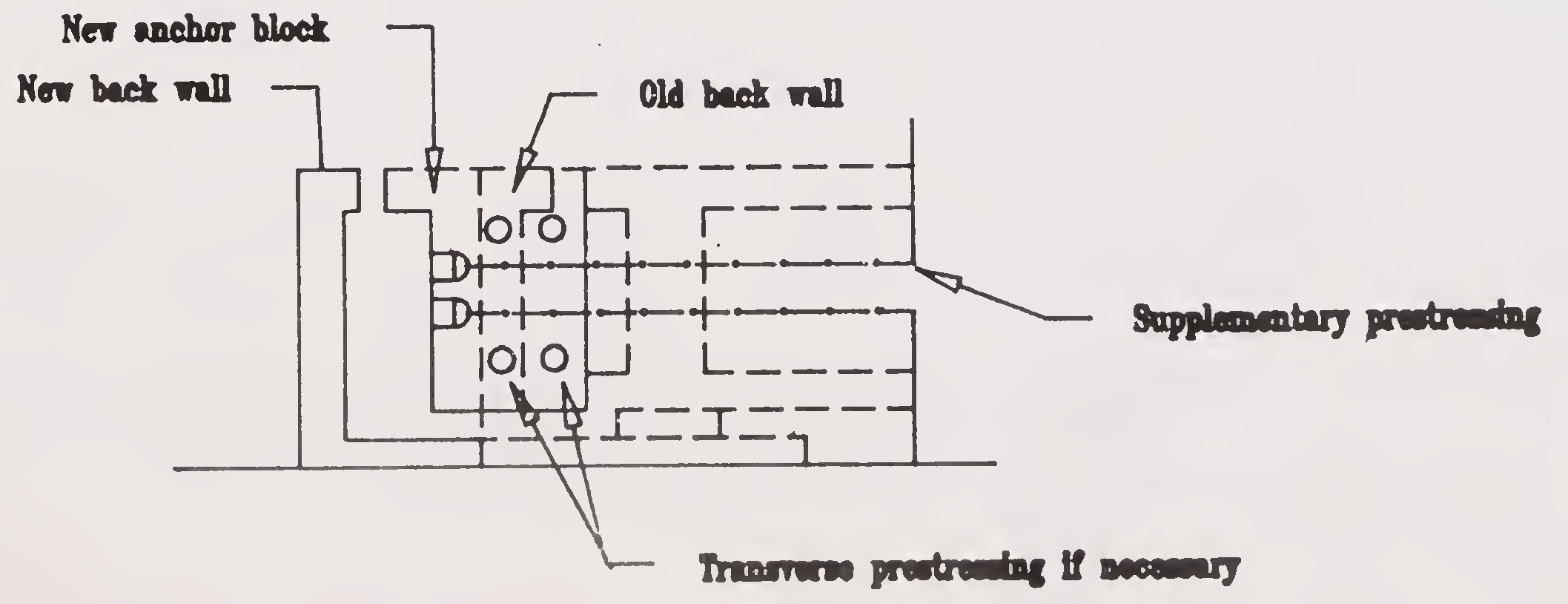
Fig. 6.2 Anchorage of supplementary prestressing elements at the end of the girder87
(ii) Additional supports,either in concrete or steel, fixed to the web of the box girder, (Fig 6.3).
This method provides a good distribution for the force in the supplementary tendons, but creates high stresses locally where the prestressing force is introduced. Because of the very short transverse dowels the fixation • of the tendon supports or brackets can be a problem.
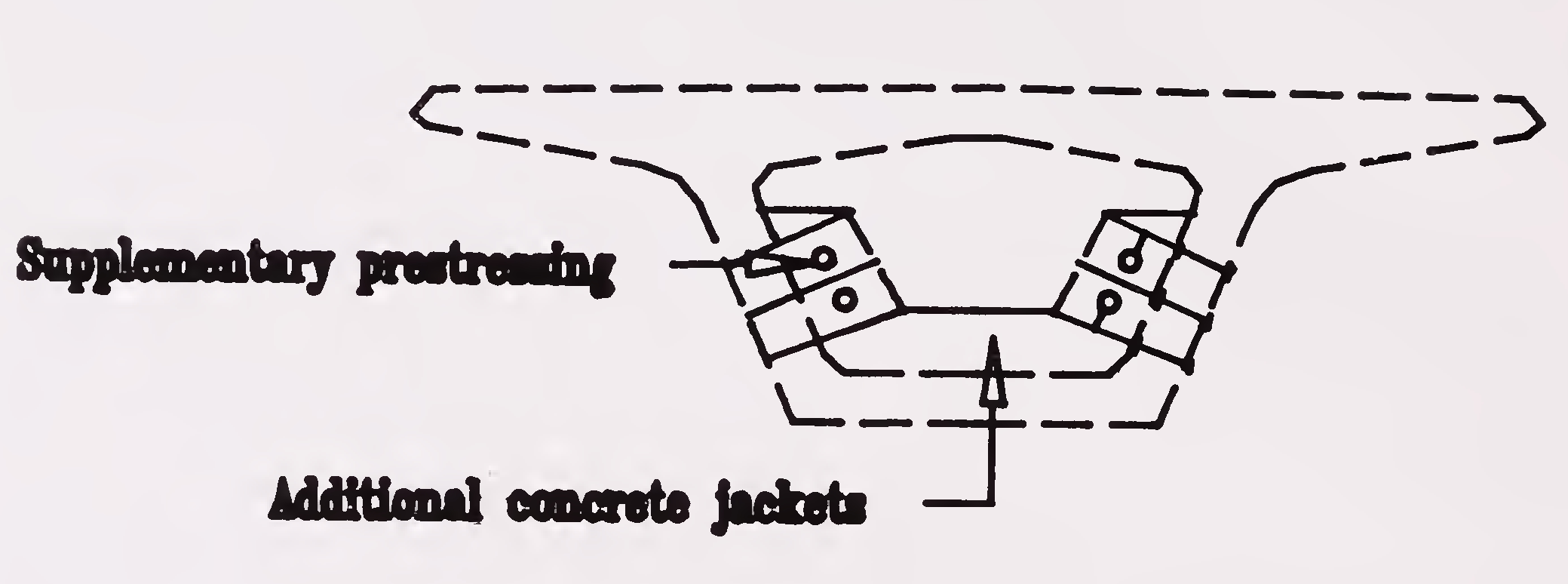
Fig. 6.3 Additional Supports
(iii)Anchorages at existing diaphragms, (Fig. 6.4 & 6.5).
Existing diaphragms require extensive coring such that the tendon can pass through the diaphragm and be anchored at the backside. If the diaphragm does not have sufficient capacity to transmit the prestressing force, it may be necessary to provide a structural steel frame to transfer the longitudinal prestressing force (Fig.6.6).
(iv)Deflectors or deviation saddles (Fig.6.7).
Where a polygonal profile is used, deviation saddles or deflectors have to be provided to achieve the profile. These devices can be either concrete or steel. They are attached to the existing webs or flanges by short perestressing bolts or other type of anchors. These short bolts or dowels are very sensitive to anchorage seating losses. A large radius of tendon curvature should be used.88
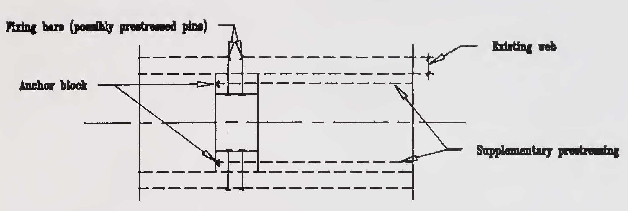
Fig. 6.4 Anchorage of supplementary prestressing elements with additional supports
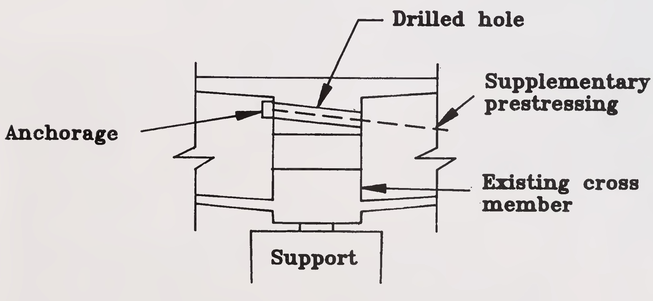
Fig. 6.5 Anchorage of supplementary prestressing at existing diaphragms89
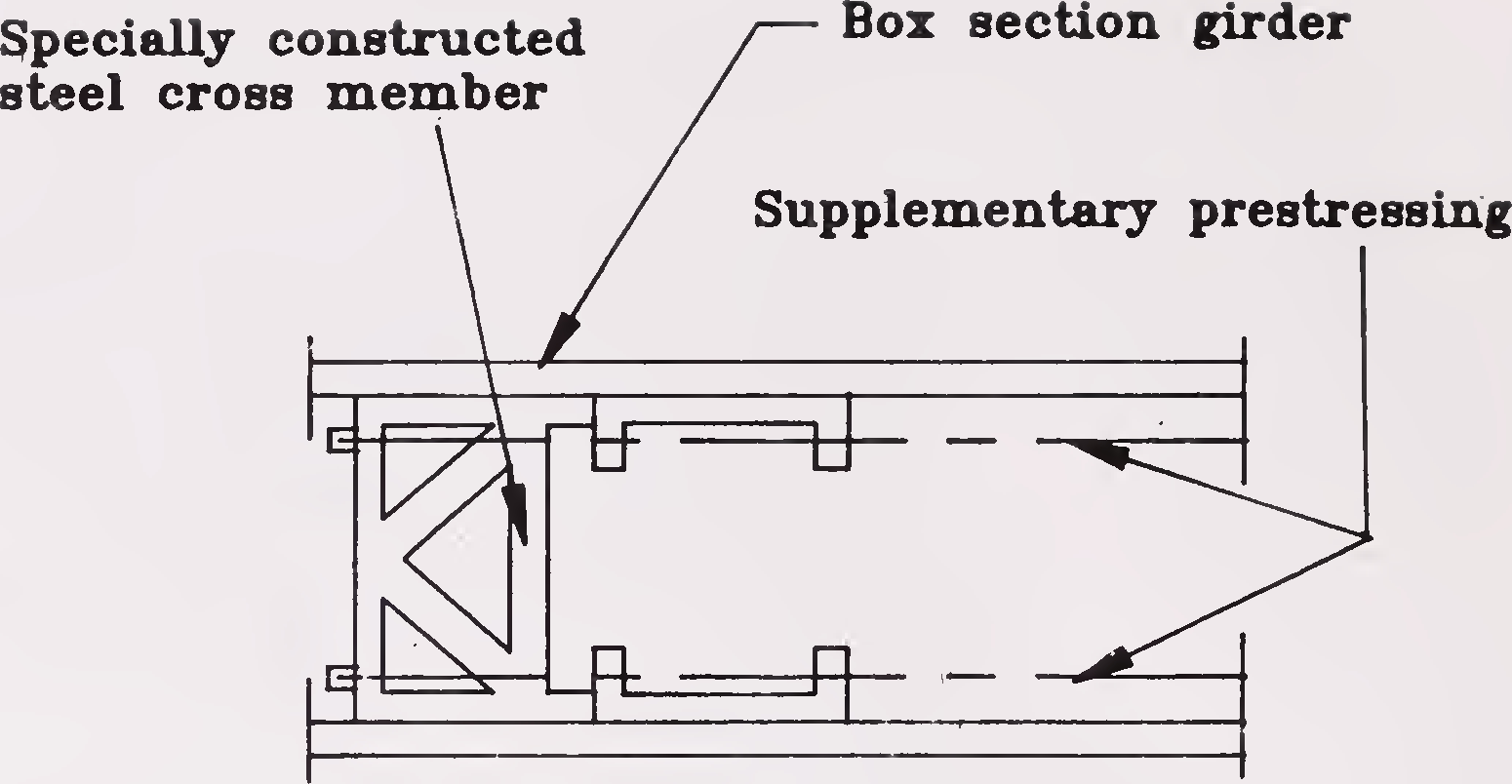
Fig. 6.6 Anchorages with auxiliary steel frames
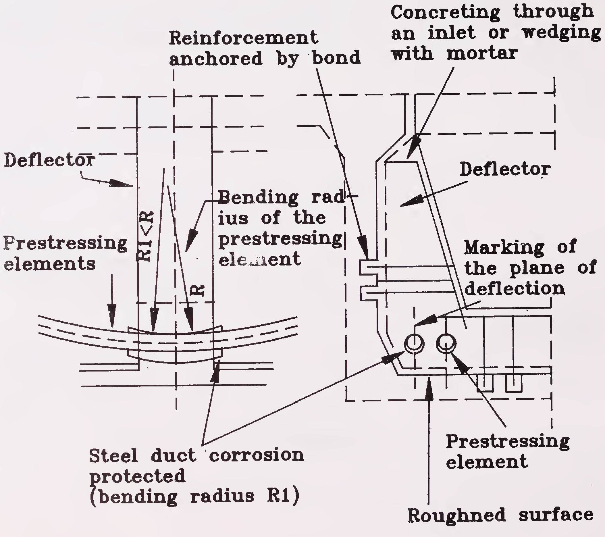
Fig. 6.7 Deflector for supplementary prestressing elements
Vertical or inclined tendons are normally used to increase shear resistance. Typical arrangement is shown in Fig.6.8.90
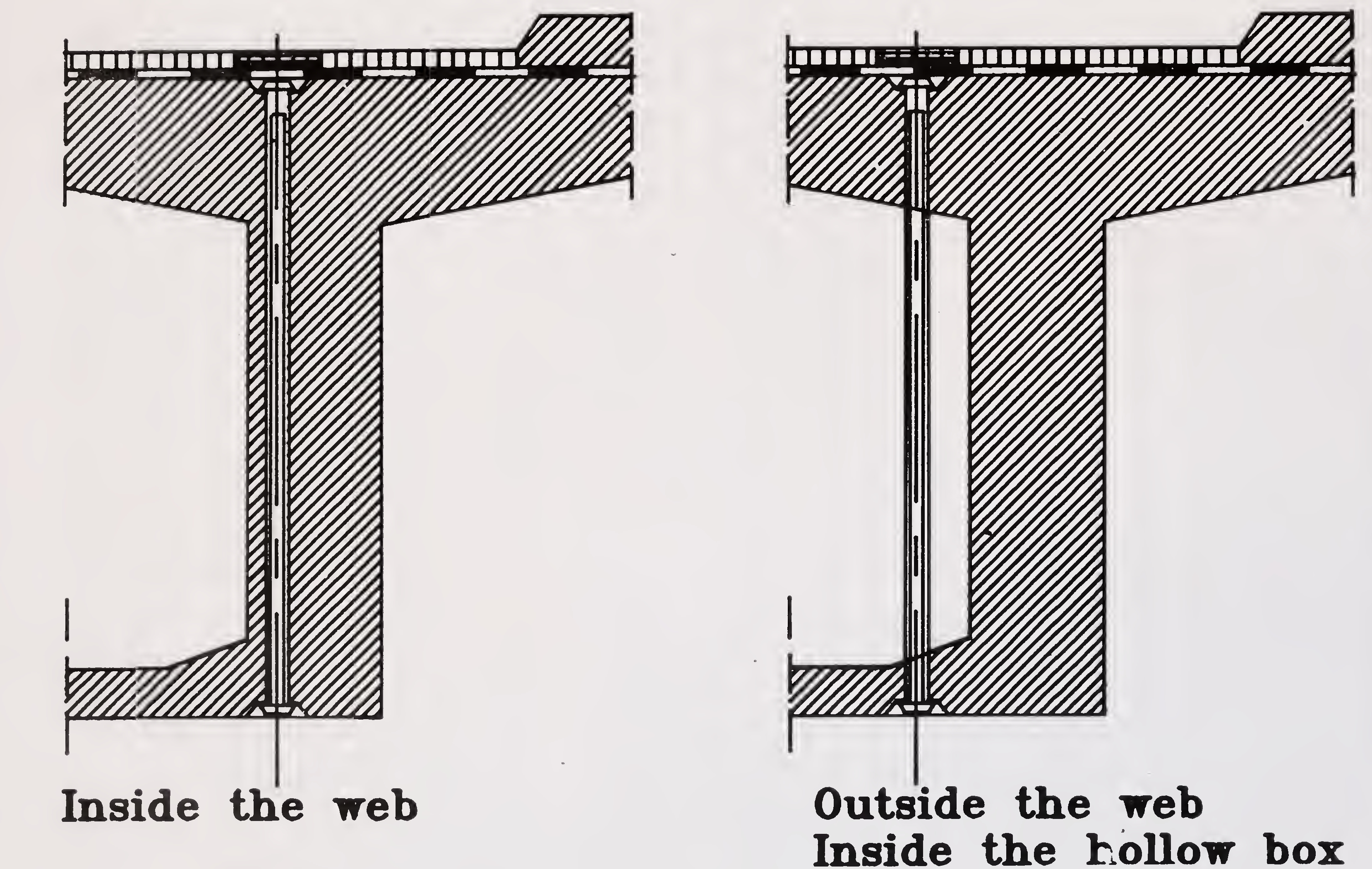
Fig. 6.8 Supplementary prestressing using straight tendons91
Strengthening is also possible by adding precast elements. This method will require a destressing (unloading) of the original cross section. The composite cross section of precast elements and the original concrete is then restressed (loaded). This provides an improved transmission of prestress force throughout the composite section. With time a re-distribiution of permanent load will occur as a result of creep and shrinkage.
This strengthening method requires bond between the two structural elements at their interface. As a rule, a resin modified cement bond mortar layer is utilized. An epoxy resin mortar can also be used.
For treatment of the contact surface of the structure, the same operations as described earlier are necessary.
In the fabrication of the precast elements, consideration should be given to the texture of the contact surface so as to provide increased bonding and shear characteristics at the interface. A sufficiently rough surface of the precast element can be obtained when the formwork of the contact surface is treated with a retarder. By early removal of the formwork and cleaning with water, a washed concrete surface can be achieved. A reduction of the largest grain size in the concrete on this surface is beneficial. Sufficient curing prevents micro-cracks between mortar and aggregates resulting from shrinkage. To roughen the surface, sand blasting is also suitable.
If no special measures are taken during fabrication, the contact surfaces of the precast elements have to be treated like that of the original structure.
By means of imposed deformation, overstressed sections of a structure can be partially relieved. With this the load carrying capacity of the whole structure is improved. A self-equilibrated stress condition can be induced in the structure by relative displacement (raising and/or lowering) of the supports or by the introduction of new intermediate supports.
It is important to note that relieving some sections of the structure will increase action effects (bending moment, shear, torsion) in other sections. A strengthening of these sections may be required. Another important factor is time: relative settlement of the supports, shrinkage and creep of the old92
structure and the new supporting elements will influence the distribution of the actions-effects in the structure.
Concrete slabs or beams or columns (piers) can be strengthened by providing reinforced concrete jackets or overlays. Normally, thickness of new concrete layer should be less than about l/3rd of the thickness of existing concrete. Proper attention to bonding and detailing of shear connections needs to be given.
Replacement of structural system or addition of new systems to the existing structure are also sometimes adopted to rehabilitate or strengthen a structure. In such cases, the existing internal stresses in the members must be carefully analysed.
Structural alterations could also be considered to reduce excessive vibrations.
An indicative decision matrix for selection of a deck rehabilitation method is given in Table 6.2. The table is not exhaustive.
| Criterion | Concrete overlay | Waterproofing membrane & paving | Cathodic protection | Rationale |
|---|---|---|---|---|
| Delamination and spalls exceeding 10% of the deck area. | No | No | Where extensive patching is required, it becomes more economical and more durable to construct a concrete overlay in short term and then rebuild. | |
| Corrosion potential more negative than 0.35 V. over more than 20% of the deck area. | No | Patch repairs and waterproofing rarely reduce corrosion activity and may accelerate it.93 | ||
| Moderate or heavy scaling exceeding 10% of the deck area. | No | No | The amount of patching becomes too expensive and consequently uneconomical. | |
| Active cracks in deck slab. | No | Cracks active under live load or temperature change are reflected in a concrete overlay. | ||
| Remaining life of structure less than 10 years. | No | No | Additional cost of a concrete overlay or cathodic protection is not justified. | |
| Concrete not properly air entrained. | No | Application of a bituminous surfacing (without waterproofing) may accelerate deterioration of the concrete. | ||
| Complex deck geometry. Skew exceeding 45, curvature exceeding 10, of changing | No | Concrete finishing machines (especially those used for low slump concrete)have difficulty in accommodating complex geometry. | ||
| super-elevation. Limited load capacity of structure | No | No | Bituminous overlay is a non- structural component. Concrete overlay can be especially useful where the span/thickness ratio of deck slab exceeds 15.. | |
| Electrical power not available | No | Power required for rectifier (unless mains solar, wind or battery power can be provided economically.94 | ||
| Epoxy injection repairs previously performed and will not be removed. | No | Epoxy insulates underlying reinforcement from cathodic protection. | ||
| Capacity after rehabilitation must be verified. Additional strengthening may be necessary. Source : Reinforced Concrete Repairs Integrated with Cathodic Protection - by Wood and Wyatt. |
||||
Operational life of expansion joints, bearings, footpaths and railings is usually shorter than that of the bridge. The expansion joints, bearings, railings, parapets etc., need special attention for repairs and replacements or renewal. The strength and efficiency of bearings may be a limiting factor in situations where it is required to increase the load carrying capacity of a bridge.
The expansion joints are not expected to last throughout the life of the bridge. It is, therefore, recommended that joints be replaced on a regular cycle. Maintenance as well as replacement of the joints will have to continue in future as well. However, there are indications that the elastomeric joints presently being installed perform better and give more satisfactory service than the previous generation joints. The need for further improvement is generally acknowledged.
It is vital to keep the joints watertight in order to prevent the ill-effects of moisture including corrosion on the beam ends, bearing shelves and substructure. Leaks must not be tolerated. It is not uncommon for joints to be watertight under the roadway but allow water to leak through at the kerb. Any95
replacement joint should be watertight across the full width of the deck, kerb, footpath, central verge, etc.
Where water tight joints cannot be provided, or where frequent failure is likely, adequate means of draining the water passing through the joints shall be provided. As far as possible, the water should be kept out of contact with the concrete and the bearings. This is sometimes difficult to realise. If these measures fail, regular maintenance of the bearings and pedestals will atleast prevent water from damaging the concrete. Joints may be filled with a sealant or filler. The filler material must be designed to ensure water tightness. Debris may prevent joint movement if the filler fails and may damage the joint sides or joint material, it may spall the sides of jointed slabs or cause over-stress in other bridge elements. Debris also tend to retain moisture and hence contribute to the deterioration of adjacent bridge component.
Some early bridges may not have adequate clearances for extreme temperature ranges.
Damage to finger type joints may manifest in the form of bent, cracked or broken fingers, as a result of traffic damage, closure of gaps and jamming due to traffic or movement of bituminous wearing course, poor alignment, loose anchorage etc. The fingers may also cave in or project up due to unacceptable deformation of the deck or differential settlement of foundation. Cracking and spalling of the pavement or deck in the area adjacent to the joint may cause subsequent failure of the joint by loosening the joint side support material. Joints can also get closed in balanced cantilever type bridges due to excessive deflection of cantilever or excessive hogging of main span.
Movement of abutment must also be considered when inspecting joints. Such movement may either increase or decrease the joint opening or may even close the joint opening completely, preventing free expansion of the bridge.
All damaged joints should be replaced. The sealant filler shall be replaced periodically. Cracked concrete in the zone of anchoring the joints shall be replaced. Periodic cleaning and removal of debris is a must.96
Most bearings will not outlast the bridge. Hence replacement of defective or damaged bearings shall be provided for. However, careful inspection and periodic maintenance of bearings can extend their service life.
Defective bearings may be due to :
The type of defect may be one or more of the following :
Appropriate corrective action shall be taken after detailed • investigation of the defects. Repair or replacement of bearings requires traffic restrictions or even temporary suspension of traffic.
Excessive tilts in bearings like segmental bearings should be corrected in time. This can be done by lifting the superstructure, shifting the bottom or top plates or extending the plates and lowering the superstructure. The cracked or excessively deformed elastomeric bearings also need to be97
replaced. This requires lifting of the superstructure. Lifting is normally done with flat jacks, but where superstructure is very heavy, cranes may have to be used. In all events of lifting, checking the design of superstructure for stresses induced due to lifting is obligatory. These specialised activities shall only be undertaken by specialist agencies.
As per the prevailing practice until recently, the footpaths have been constructed either in-situ or using precast slabs with a gap between the top of deck slab and soffit of the footpath slab. The common distress noted in either case during the service life is in the form of cracks. In addition many other precast slab components are also found displaced or missing. The kerb line, footpath/deck joint area is particularly sensitive to deterioration and should be checked.
The cracks shall be repaired by injecting either cement grout or epoxy as appropriate after detailed investigations. The broken/missing precast panels shall be replaced with panels of better designs and strength. It may also be appropriate to provide a mastic topping over the cracked precast slabs.
Where major replacements of precast planks is envisaged, it may be desirable to revise the design and provide for solid in-situ footpath slab.
The repair measures for these will be same as are to be done for similar items of which these railings or parapets are made of. A decision to repair or replace these items should be taken keeping in view the economics and importance of appearance of the bridge.
Corrosion of holding down bolts on railing is a particular problem that should be watched.
This Chapter has been introduced mainly to focus attention of the bridge engineers on this major cause of frequent damages to bridges. Due to inadequate knowledge and uncertainties about many aspects of bridge hydraulics and river behaviour in general, it is not possible to lay down98
guidelines which can claim to have a general validity of application. Some of the most common hydraulic deficiencies which could occur are as under :
The causes for occurance of these and other similar deficiencies have to be explored, examined and thereafter suitable remedial/rehabilitation measures may be adopted so as to ensure safety and serviceability of the bridge structure.
An attempt has been made to mention a few examples of the common rehabilitation measures for damages caused by floods.
A bridge structure can substantially get damaged by floods. There are cases where rehabilitation of bridges become necessary on account of changes in the hydraulic parameters as manifest during flood conditions. The damages can be caused due to (1) abnormal floods, (2) normal floods, if the design of the bridge does not cater adequately to the normal design floods and/or (3) as in a few cases, due to man-made changes in catchments of watercourse, e.g. the flood levels may exceed the original design levels substantially due to back water effect of a storage constructed downstream requiring raising of the bridge superstructure.
Floods can damage both the bridge structure as well as the approaches and the protective measures. The bridge engineer is advised to refer to IRC: 89-1985 "Guidelines for Design and Construction of River Training and Control Works for Road Bridges."99
If either due to inadequacy of original hydraulic design or due to the requirements of traffic as in a submersible bridge, the bridge level has to be raised, the same can be done by raising the superstructure with the help of jackets and extending the sub-structure in suitable stages by successfully resting them on the precast concrete pads which can then be embedded in the raised height of the piers. Where, however, the bridge deck is not to be raised but the bridge has to be protected from floods higher than the design floods, then designing the bridge as a submersible one and strengthening the same may have to be explored. At the same time suitable corrective measures may have to be adopted for decking and approaches, like provision of air-vents between the girders, protection of embankment, strengthening of piers by jacketting etc.
When the velocity and consequentially calculated scour in the stream is expected to increase and the substructure is found to be unsafe under such conditions, a solution of paving the bed with suitable aprons upstream and downstream can be considered to prevent the scour around the piers and the piers may also be strengthened by jacketting. If partial submergence of the bridge is unavoidable and if the live load on the bridge is found to cause excessive stresses, then it may be necessary to provide spilling section in the approaches so that the live load is automatically cut off when the water level exceeds a specific limit.
If damages to the bridge and approaches are of frequent nature then after careful investigations it may be necessary to extend the length of the bridge to provide adequate waterway. If the floods attack one side of the bridge, then additional spans could be provided on the affected side. Sometimes such situation can be handled by adequately designed spurs or groynes. In some cases, the returns beyond the abutments get damaged and may require replacement by returns on deeper foundations. Where a pier gets damaged beyond repairs, the span lengths could be changed either by locating a pier in between or if possible, by doubling the spans with suitable strengthening of the remaining substructure.
Bed protection can get damaged due to excessive turbulent floods or disturbance of stone protection. Surfaces of concrete or masonry can get eroded by high velocity of stream and sometimes cavitation can occur.
The bridge hydraulics is a highly specialised subject and so the treatment of the damages must be designed and carried out after consulting a specialist. Even the IRC general guidelines may have to be modified and supplemented according to subjective and objective judgement of the engineer100
to cater for such river and specific requirements of a bridge. Use of hydraulic model studies for specific problems is also of considerable help in arriving at a proper solution.
After the rehabilitation/strengthening of the structure is completed, it is essential that the bridge structure is kept under observation and its condition monitored regularly so that any distresses are located promptly and corrective measures taken well in time. It is essential that the form of monitoring is specified and inspections are carried out according to a calendar which should be prescribed. The various methods of monitoring the bridge structures are given in the succeeding paragraphs.
During the distressed stage of a bridge and after the distressed bridge has been rehabilitated or strengthened, it is necessary to carefully monitor its behaviour for a certain period of time to ascertain its performance and the efficacy of the measures adopted. The monitoring would involve carrying out certain laboratory and field tests as well as condition surveys and measurements to detect even small strains, movements, changes in reaction and deformations.
The first and the foremost requirement is to carry out principal inspections at more frequent intervals than for normal structures, say immediately after distress is noticed and on completion of the remedial measures and, during the use of the structure, at the intervals of 6 months or 1 year thereafter for a period of 2-3 years. These need to be repeated often after carrying out some of the investigative tests particularly, when any signs of arousing suspicion are discovered. Use of mobile inspection units to have an access to each and every part of the bridge is a must for the principal inspections. The techniques of underwater inspection described earlier may also be adopted.101
The usual methods adopted for monitoring the behaviour of a structure are :
(a) Observing deflections by periodically taking levels. Deformations can be also monitored by water levels in tubes connected to tank filled with water. The movements of bridge can be measured at the joints using slide gauges for maximum/minimum movements and reference pins for routine check.
(b) Visual observations (looking for cracks, deflections, overall integrity, profile, functioning of bearings and hinges, corrosion stains, etc.) Particular note must be made of the cracking pattern, their width and length and whether cracks can be due to plastic shrinkage, settlements, structural deficiency, reactive aggregates, corrosion etc. Signs of delamination, spalling, hollow or dead sound when tapped with hammer, honeycombing and expansion of concrete should also be observed. Frequency and levels of inspections have to be specified depending on individual circumstances.
(c) The change in the width of the cracks with the passage of time needs to be observed through tell-tales and Demec gauges to know whether the cracks are static or live.
(d) Plumb bobs are used to measure deviation from verticality for vertical members ; Special tilt meters or inclinometers also could be used; (N.B Datum readings at the time of construction are essential).
(e) Opening of joints, particularly, near the hinges, expansion joints, etc., need to be observed.
(f) Redistribution of support reactions may also be measured in some cases.
The use of permanent electrodes for accurate measurement of the corrosion potential of steel in concrete is also made. Use of current density or rebar probes and the use of corrosion rate monitoring probes can be made to meet the particular requirements. Careful selection of permanent monitoring equipment is required. The locations should be minimum and should be at the area of most active corrosion rate.102
Relatively thin steel wires are embedded in the structure near the reinforcement with permanent electrical connections to the tale- tells so that electrical resistance can be measured. Corrosion of tale- tells would cause an increase in the electrical resistance. Certain devices can be permanently embedded in the concrete for facility of later measurements of the extent and the rate of corrosion in future years. However, the evaluation of such instruments is yet to be perfected. A new probe has been recently developed for evaluation and control of steel corrosion in marine concrete structures to provide information about the corrosion condition for both the embedded and externally exposed steel. The probe gives information on the passsivity of the embedded steel, electrical resistivity and the oxygen available as well as the corrosion rates.
The measurement of strains at critical sections or joints is another method of monitoring the behaviour of critical bridge elements. Electronic strain gauges are fixed at predetermined points. Sometimes dial gauge type strain gauges are also provided. However,it is the experience that these gauges do not work efficiently in outdoor atmosphere.
Application of lasers in structural monitoring is finding increasing use in developed countries. In its simplest form the system consists of threading a laser beam through series of apertures in the plates fixed along the length of the beam,say along the soffit of a girder or soffits of series of adjoining girders, (Fig 9.1). Simililarly, a laser beam can also be directed vertically along the bearings or a column. The beam after passing through a series of apertures in plates thus fixed along this path reaches the light sensitive receivers at the farthest end. The failure of the beam in reaching the receiver requires further investigation because it could be due to some structural deformations of the members supporting the plates or due to some other reasons. A system of series of such laser beams can be provided in a structure and arrangement made to sound an alarm in case of blockage of light of any laser beam.
Further refinement of the system could be made by attaching detectors to the structure along the path of the laser beam whereby any movement of the structure at the location of each detector would be continuously tracked by the latter relative to the laser beam and the actual overall behaviours of the structure at each detector location can be measured, recorded and analysed with the help of computers controlling timing and the operational sequence of the various detectors. Readings to the accuracy of even 0.1 mm are possible and103
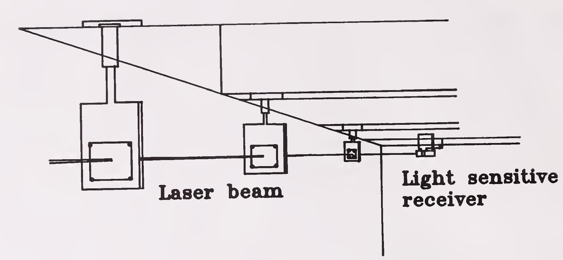
Fig.9.1 Laser monitoring of deck girders
continuous and constant 24 hours-a- day monitoring of a structure for its integrity and soundness is possible.
Measurements for vibration characteristics of a structure can also be adopted in some cases to monitor the continued structural integrity and strength in the long run. However, a specialist’s guidance should always be obtained
Instrumentation has to be provided for proper monitoring of long span bridges to study their behaviour during their service life. The measurement may include concrete strain at critical points, temperature effects, deflections, movement of hinges, etc.
Monitoring of distressed bridges as well as rehabilitated bridges requires a great deal of skill and specialisation. The engineers maintaining and inspecting such bridges therefore will need to be trained for such jobs.
Monitoring also requires setting up a data bank as a reference frame. This should be initiated at the time of construction.
Testing, measurements and analysis of data are important to monitor the condition of the bridges. The sampling frequency of testing,104
therefore, has to be decided with the help of an expert. In the beginning, an extensive random sampling could be adopted to study the variability of the results. Later, after studying the variability of the results limited target sampling may be decided. Both in selecting the sample size and the interpretation of the results, expert guidance is absolutely essential.
Repairs and rehabilitation is as much an art as it is a science which is not yet fully developed and has quite a few imponderables. Some techniques and materials are still under development. These limitations should be well understood. This chapter, though strictly not a part of the Guidelines, has been added only for information to indicate some areas requiring research and development. Needless to say that the list is not complete.
This Chapter should be read in conjunction with the recommendations for research given in Chapter 6 of IRC: SP: 35. In seeking to devise improved ways to rehabilitate and strengthen bridges, it is necessary to meet the criteria of practicality as below:
The goals for future research and development will have to be (a) to establish durability oriented technology for design and construction of bridges to be accomplished by developing standards, codes, specifications and9105
detailing and (b) to increase the service life of the existing bridges by improving methods of investigation to quantify the level and rate of deterioration and by containing the future deterioration.
Different areas which call for intensive research and development effort to achieve better rehabilitation and strengthening of bridges are :
There are certain important aspects of rehabilitation and strengthening of bridges involving measures other than technical which deserve due attention at various stages by concerned authorities. These are :
After completion of every such job of rehabilitation of a bridge, an engineer must prepare a document to enable drawing lessons for the future so as to improve the bridge technology. Provisions must be made in structures at the design stage itself for the possibility of future interventions like rehabilitation, strengthening, replacement of some components etc. A number of fruitful lessons can be learnt from the adverse experiences on the bridges and the consequent improvement of bridge technology.108
REFERENCES
| (1) | OECD Road Research - "Bridge Inspection OECD" Paris, 1976. |
| (2) | OECD Road Research - "Evaluation of Load Capacity of Bridges" OECD, Paris, 1979. |
| (3) | OECD Road Research - "Bridge Maintenance" OECD Paris, 1981. |
| (4) | OECD Road Tran sport Research - "Bridge Rehabilitation and Strengthening" OECD, 1983. |
| (5) | OECD Road Transport Research "Durability of Concrete Bridges", 1989. |
| (6) | Transportation and Research Board - "Underwater Inspection and Repair of Bridge Structures Programme - Synthesis of Highway Practice 88", Washington DC 1981. |
| (7) | Ministry of Transportation and Communication - "Cathodic Protection for Concrete Bridge Deck Restoration", 1981. |
| (8) | FIP Guide to Good Practice - "Inspection and Maintenance of Reinforced and Prestressed Concrete Structures", 1986. |
| (9) | FIP Guide to Good Practice - "Repair and Strengthening of Concrete Structures", 1989. |
| (10) | "Sea Water Corrosion" - Published Search, U.S.Department of Commerce, National Technical Information Service (NTIS) |
| (11) | "Detection of Flaws in Reinforcing Steel in Prestressed Concrete Bridge Members (1981)", U.S.Department of Commerce (NTIS). |
| (12) | Special Report 84-25 - U.S.Army Corps of Engineers. - "Salt Action on Concrete" (1984). |
| (13) | "Guidelines for Evaluation and Repair of Prestressed Concrete Bridge Members" (Dec. 1985) - U.S.Department of Commerce (NTIS). |
| (14) | "Durability and Behaviour of Prestressed Concrete Beams Report 6" (1984) - Department of the Army, U.S.Army Corps of Engineers. |
| (15) | "Repair of Concrete Damaged by Reinforcement Corrosion" - Concrete Society, London (1984), U.S.Department of Commerce (NTIS). |
| (16) | Wood, R.G. and Wyatt, B.S. "Reinforced Concrete Repairs Integrated with Cathodic Protection." |
| (17) | Gabriel, David A. "Application of Lasers in Structural Monitoring". |
| (18) | Merani, N.V. "Investigation and Rehabilitation of Distressed Concrete Bridges" -I.R.C. Vol.51-3 (Nov. 1990).109 |
| (19) | "Guide to Assessment of Concrete Strength in Existing Structures" B.S.6089 - 1981. |
| (20) | British Standard Testing Concrete - Part 201. "Guide to the Use of Non-destructive Methods of Test for Hardened Concrete".
- B.S. 1881 : Part 201 : 1986 - Section I and Section II - Part 203 - 1986 - "Recommendations for measurements of velocity of Ultrasonic pulses in concrete". |
| (21) | "Guidelines for Design and Construction of River Training and Control Works for Road Bridges" - I.R.C.: 89 - 1985. |
| (22) | "Guidelines for Inspection and Maintenance of Bridges" -I.R.C. SP: 35 -1990. |
| (23) | "Guidelines for Evaluation of Load Carrying Capacity of Bridges" - IRC: SP: 37 - 1991. |
| (24) | Relevant Papers published in IRC Journal and Bridge and Structural Engineering.110 |
APPENDIX-1
QUANTITATIVE MEASUREMENT OF CORROSION OF STEEL IN CONCRETE
Recently a few electrochemical techniques have been experimented with good degree of correlation with the actual corrosions. In all the techniques, one electrical terminal is taken from the reinforcement network at some convenient point. A probe sensor is then moved on the concrete surface along the rebar network profile. Corrosion current flowing at different locations between the sensor on the concrete surface and the steel rebar just below the sensor in that location is measured.
Galvanostatic pulse technique :- A short time anodic current pulse (typically some seconds) is imposed on to the reinforcement galvanostatically from a small probe on the concrete surface and the resulting change in potential is recorded with a recorder for further calculations. Battery powered galvanostats are used.
Polarisation resistance technique :- Main instruments required are a potentiostat and a wave analyser. Using a suitable sensor, the potential of the steel rebar at any location is shifted by a small amount and the resulting current is recorded. From the slope of the curve, corrosion current is calculated. Contribution from the concrete resistance is deduced through A.C., impedance measurement at higher frequency and deducted to get the true polarisation resistance. From polarisation resistance values, the corrosion current is determined.
A.C. Impedance:- A Frequency Response Analyser is employed. A small amplitude voltage sine wave is applied and the current response is obtained as modulus of impedance and phase shift for various frequencies.
In all the above techniques, the measured value relates to polarisation resistance 'Rp' or 'Rt'.
Corrosion rate ‘X’ in um/year is obtained as follows :
 where
where
K is conversation constant
B is stem-Geary constant
A is surface area (sq.cm)111
Harmonic Analysis :The method is relatively quick and easy to perform on site with a portable frequency response analyser which has suitable harmonic facilities. Direct reading of corrosion rate is possible.
It is to be pointed that polarisation resistance technique is a practical and simple on-site corrosion-rate-measurement technique provided a suitable probe and instrumentation are used.112
APPENDIX -2
SELECTION OF TECHNIQUES AND MATERIALS
Adoption of a particular technique will be governed basically by the end requirements of structural repairs. Choice of materials shall also depend on various factors such as compatibility with the structure, availability of the equipment etc. While tackling structural repairs, several situations may be encountered. Choice of different techniques and materials as given in the table below is after considering such situations. The list given in the table is not exhaustive but only indicative of some commonly adopted techniques and it is possible to use these techniques/materials in combination with other methods.
Detailed description will be found in earlier chapters. In this, only summary is attempted.
| Sr. No. | Type of Material of the Bridge | Component of the Bridge | Type of distress of damage | Suggested Remedial Measures | |
| Repairs/Rehabilitation | Strengthening | ||||
| I | Masonry Bridges | (A) Foundations | Undermining, Scouring Settlement | River Training Protection by Sheet Piling | — |
| Settlement | — | Modification of the foundation, jacketting etc.113 | |||
| (B) Sub-structure | Leaching of mortar in joints surface deterioration | Epoxy mortar painting and injection of epoxy surface protection. | Guniting, Jacketting | ||
| (C) Super-structure | Cracking, loosening of Stones/bricks | Treatment by epoxy resin and mortar | Bonding of steel plates, Guniting | ||
| Leaching of joints, surface deterioration | Protective coating | Adding material to the intrados or extrados in case of Arch Bridges | |||
| II | RCC Bridges | (A) Foundation | Deterioration, Structural Damage, Sinking of foundation, Erosion | Protection and replacement of material. River Training by sheet piling, garlanding etc. | Modification of the foundation, jacketting etc. |
| (B) Sub-structure | Spalling, Cracking, Disintegration, Sealing, Corrosion of reinforcement | Repair to concrete surface by cement mortar or resin systems. Injection of epoxy, Surface protection, Replacement of reinforcement. | Guniting with treatment to reinforcement and using bonding agent, jacketting. | ||
| (C) Superstructure | Surface deterioration spalling honey combs cracks disintegration, corrosion of reinforcement | Surface preparation by mechanical or chemical means with the use of sand blasting-Demolition of concrete by jack hammers, chisels explosives etc. | Strengthening by external reinforcement such as bars or epoxy bonded plates.114 | ||
| Bonding agent such as cement mortar/paste Impregnation with silicon, organic solutions, resigns or oils Replacement of concrete section -careful pretreatment of surface and building up the section by resin system or cement mortar with plastic modification. Repair of cracks by proper selection of epoxy polyurethene resips. Acryl resins etc. and with suitable injection equipment. Shotcrete Gunite Protective coating. Removal of Chloride contamination - physical removal of affected concrete (wherever possible) and rebuilding the section115 |
Strengthening by post-tensioning-Using external prestressing cables suitably anchored at the end of the girder. | ||||
| III | Prestressing Concrete Bridges | (A) Foundation | Details given under PSC bridges, and as | "RCC Bridges" are also applicable to these components of such not repeated. | |
| (B) Substructure | -do- | -do- | |||
| (C) Superstructure | Surface deterioration, Cracking, Spalling, Damage, Corrosion of reinforcement | Repair methods suggested under "RCC Bridges" can be applied here also. | Strengthening by external Cables. Epoxy bonded plates. |
||
| Corrosion of cables | Cleaning of prestressing cables and re-grouting | ||||
| Loss of Prestress | Complicated solution involved. | ||||
| IV | Steel Bridges | (A) Foundation | — | — | — |
| (B) Substructure | Weakening of members | Replacement of weak or defective members | Introduction of extra load carrying elements. | ||
| (C) Superstructure | Decrease in load carrying capacity | Splicing | External prestressing of the beams and similar members. | ||
| Cracking | Introducing new members116 | ||||
| Corrosion, pitting Fatigue, Loosening of Bolts and rivets etc. | Protective coating, Replacement of bolts and rivets. | Addition of Stiffeners to flanges webs and diaphragms. | |||
| Abnormal deflections. Buckling, working or kinking of elements necking, yielding | |||||
| V | Composite Bridges |
(A)Foundation (B)Sub-structure | Details given in I to IV be applicable in pertinent particulars | I to III above shall be applicable in pertinent particulars117 | |
| (C) Superstructure | Not many references are available. Defects in concrete or steel shall be dealt as per manner described under s.No. II to IV. | ||||