 4
4This library of books, audio, video, and other materials from and about India is curated and maintained by Public Resource. The purpose of this library is to assist the students and the lifelong learners of India in their pursuit of an education so that they may better their status and their opportunities and to secure for themselves and for others justice, social, economic and political.
This item has been posted for non-commercial purposes and facilitates fair dealing usage of academic and research materials for private use including research, for criticism and review of the work or of other works and reproduction by teachers and students in the course of instruction. Many of these materials are either unavailable or inaccessible in libraries in India, especially in some of the poorer states and this collection seeks to fill a major gap that exists in access to knowledge.
For other collections we curate and more information, please visit the Bharat Ek Khoj page. Jai Gyan!
IRC:SP:11-1984
(Second Revision)
Published by :
INDIAN ROADS CONGRESS
Jamnagar House, Shahjahan Road,
New Delhi 110011
1984
Price ₹ 300
(Plus packing & postage)
Quality control of construction materials and product is an essential requirements for obtaining improved and uniform standard of roads. Towards this end, a three-day Symposium on ‘Quality Control in the Construction of Roads and Runways,’ was organised under the joint auspices of the Indian Roads Congress and the Central Road Research Institute in New Delhi from 27th to 29th February, 1968. At the concluding Session of this Symposium, the following resolutions were adopted :
In pursuance of Resolution No. 4, a Committee consisting of the following members was constituted for drafting the Handbook:
| (1) Shri S.N. Sinha | Convenor |
| (2) Shri M.K. Chatterjee | Member |
| (3) Shri J. Datt | " |
| (4) Dr. M.P. Dhir | " |
| (5) Dr. R.K. Ghosh | " |
| (6) Shri T.K. Natarajan | " |
| (7) Dr. M.L. Puri | " |
| (8) Shri R.P. Sikka | " |
| (9) Dr. Bh. Subbaraju | " |
| (10) Prof. C.G. Swaminathan | " |
| (11) Dr. H.L. Uppal | " |
The above Committee, in turn, constituted four Subcommittees to prepare drafts of various Sections. Later, the Committee decided that, before finalising the Handbook, its main tentative recommendations regarding the quantum of testing, control tests, acceptable tolerances and method of interpretation of results, in a summarised form, be placed before the National Seminar on Roads and Bridges at Bombay in October, 1968 for wider discussion. For this purpose, a Working Group consisting of Dr. M.L. Puri, Dr. M.P. Dhir and Shri R.P. Sikka was entrusted with responsibility of preparing the required summary for circulation to the delegates attending the National Seminar.
The Recommendations of the National Seminar were discussed by the Committee and in light of the discussions, a drafting Subcommittee comprising Prof. C.G. Swaminathan, Shri T.K. Natarajan and Dr. M.L. Puri was formed to complete the draft.
The draft prepared by the Subcommittee was discussed by the Committee in a series of meetings and a Working Group consisting of Shri R.P. Sikka, Dr. M.P. Dhir and Dr. M.L. Puri processed the same. It was then considered by the Executive Committee of the Indian Roads Congress, in its meeting held at Gandhinagar on 25-11-72. Thereafter, the Council of the Indian Roads Congress at its meeting held at Gandhinagar on the same day finally approved the draft of this Handbook of Quality Control for being published as a Special Publication of the Indian Roads Congress.
The Manual was revised in 1977 (First Revision) to incorporate the new standards on surface evenness approved by the I.R.C. Council at its Meeting held in Madras on 28.8.76. The second revision includes the prescribed equipment for different laboratories and the forms to be used for recording the results of observation/test results by the field officers.
Quality control is an essential part of any production process and highway constructions are no exception. Quality control is an important requirement for highway construction for ensuring quality and for creating durable national assets. The need for quality control on these constructions has increased considerably in recent times due to a significant increase in traffic intensities, and the level of service expected of highway facilities. Improved level of service of the highways will result in considerable savings in vehicle operating cost and in favourable road user reaction and public opinion. Quality control in the form of sensory checks which are intrinsically subjective and qualitative is grossly inadequate for present-day needs and must instead be based on proper objective and quantitative measurements.
It is common knowledge that quality control, besides leading to constructions of improved quality and uniformity, and ensuring a more economical utilisation of materials, also affords a significant reduction in user costs, in terms of lower costs of vehicle operation, transportation and maintenance. The extra cost of exercising quality control being only a fraction of the resulting benefits, is a highly economical proposition, in as much as on an average project it is estimated that the cost of exercising quality control would be just 1½ to 2 per cent of the construction cost. On the other hand, the direct and indirect economic return from quality control could be of the order of 5 to 10 per cent of the total construction cost and even more.
The pre-requisites for effective control of highway constructions are :
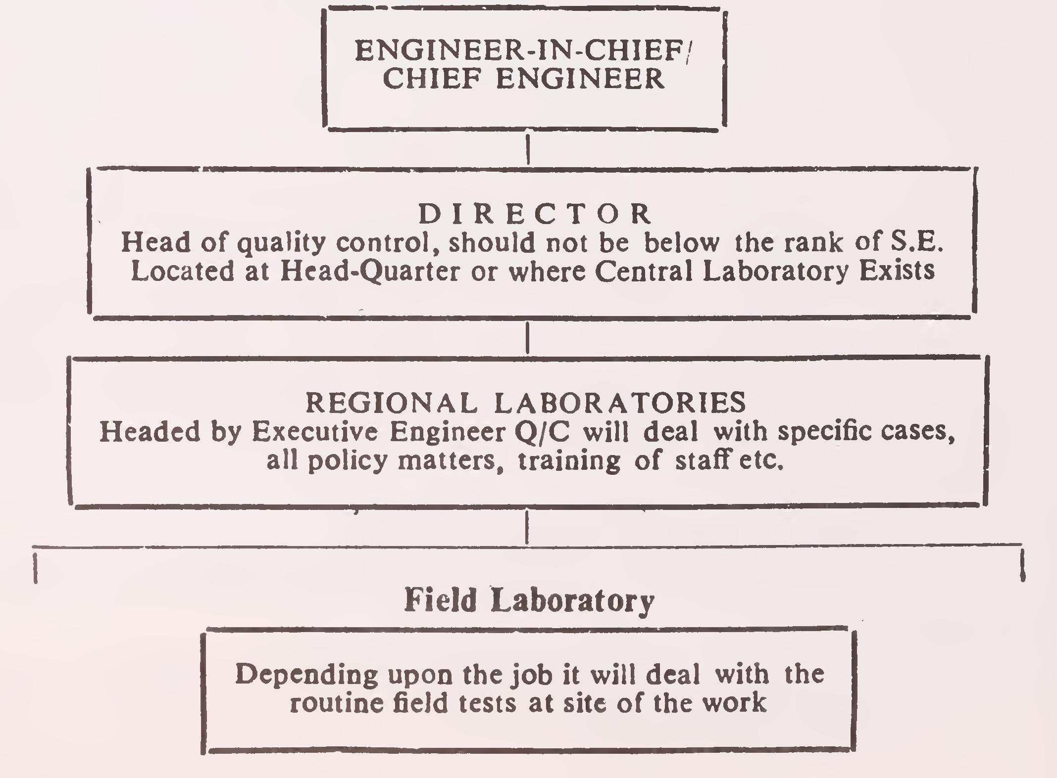
The requirements of a quality control organisation will obviously vary on different projects depending on the departmental set-up of the concerned highway agency. For. example, the organisation of quality control work at a single centrally situated large project will need to be on quite different lines than at average sized scattered projects. In this chapter only the broad guidelines for the organisation of quality control work at road projects are discussed. The actual set-up may be evolved in the background of various factors involved. For the suggested pattern of quality control set-up in this handbook a typical Organisational set-up has been drawn up and shown below:
Organisational Chart of Quality Control Set-up
4
In any organisational set-up, the central agency has an important role as regards implementation of quality control standards by way of drafting and constant review of the quality control criteria included in the construction specifications. The implementation of quality control in the field would normally involve three sub-agencies viz. the construction staff of the Engineer-in-Charge, the constructing agency and the quality control team. The construction staff and quality control teams must have distinctly defined functions and inter-relationships so as to avoid possible conflicts. The quality control team may consist of staff of regional laboratories and field laboratories working under the technical direction of the Central Laboratory.
As far as the field laboratories are concerned, the periodic quality control data collected by them should be promptly fed to the site engineer, as the latter is responsible for ensuring quality and speed of construction. In addition, the data will also be submitted to the Superintending Engineer/Chief Engineer as well as to the Head of the Central Laboratory; to the former with a view to ensure continuity as well as compatibility of the specifications in practice, and to the latter for purpose of feedback. This may be regarded as a tentative recommendation, subject to review and modification, as and when experience accumulates.
The expenditure on quality control may be charged to the works and the staff as well as equipment shifted from project to project depending upon the requirements. The quality control staff should not be on work-charged basis but form part of regular staff and be properly trained for the work they are required to handle, for which suitable training facilities should be afforded by the department, either in their own Central Laboratory or any other Laboratory. To provide for the cost of quality control, it is suggested that this may be included as a distinct item in the various work estimates.
Over the years, two types of methods have emerged for exercising quality control during the construction of works. One is generally known as 'Process control' and the other as ‘End5
result’ type of control. In the former, the designer makes the decisions regarding the type of equipment, the procedure of construction and the amount of work required to obtain the desired result. In the 'End result' type of control, the construction agency, which may be a private contractor, has a free hand in the selection of construction methods and equipment to achieve the desired end product.
The choice of either type of control is largely a matter of judgment, depending on the magnitude of the job, different environmental factors involved and the available facilities. In India, gradually the trend is towards ‘End result’ type of working on highway pavement and embankment construction jobs. But in several situations, for example on small jobs, or where input type of tests like material gradation and purity of lime are to be carried out, expediency would be in adopting ‘Process type’ of control. Because of circumstances, a combination of the ‘Process’ and ‘End result' types of control will continue to be adopted in India, depending on the nature and size of the job.
In the ‘End result’ type of specification, the field engineering personnel carry out tests on finished work at regular intervals to evaluate whether it meets the specification requirements or not. On the other hand, in ‘Process type' control, the responsibility of field personnel is to make sure that the work in its different phases is executed in the manner predetermined and laid down in specifications.
The details given in this Handbook arc for a combination of ‘Process’ and 'End result' types of quality control which is generally being practised in this country.
The handbook draws heavily upon the existing Standards/ Specifications of Indian Roads Congress by way of abstracting essential requirements of construction for the various items of work. Reference is given to the relevant Standards at appropriate places in the Handbook. A complete list of all the standards referred to with their full title is included at Appendix 1.6
The quality control tests on materials indicated in the subsequent chapters, are intended essentially to be carried out on the material brought to site. However, at times, from practical and other considerations, some testing could be done advantageously at the material source. In these circumstances, The Engineer-in-Charge may do additional testing at site as may be found necessary to ensure that the materials being incorporated in the construction are of specified quality.
All the materials brought to the site shall be stacked and stored as specified so as to prevent deterioration or intrusion by foreign matter and to ensure the preservation of their quality and fitness for work. Materials which have been improperly stored or have been stored for long periods shall be re-tested where their suitability for incorporation in the work is in doubt.
The procedure for testing of different materials and work shall be in accordance with the relevant standards of Indian Bureau of Standards where these are available. Reference has been drawn to these standards at appropriate places in the Handbook. A consolidated list of the standards with their full title is at Appendix 2.
Where specific procedure of testing is not indicated, the tests shall be carried out as per the prevalent accepted engineering practice to the direction of the Engineer-in-Charge.
The frequency and extent of testing indicated in the Handbook is the minimum considered necessary for normal conditions. It is envisaged that additional testing shall be carried out for abnormal conditions where variations may be excessive or where circumstances so warrant otherwise.
Acceptance Criteria for different items of work where sufficient experience was available have been setforth in the Handbook in respective chapters. For other items, acceptance7
may be based on minimum values or statistical analysis as is considered judicious.
For effective control on quality of materials and work, it will usually be necessary to lay down the acceptance criteria in the contract documents.
Range of equipment required for a central, regional and field testing and control laboratories is indicated in Appendix 3 for guidance. The list includes such equipment as will normally be required for quality control operations spelt out in the Handbook. Individually, quality control units could be suitably equipped with the help of this list depending on the type and volume of work to be controlled. Special equipment as given in the appendix can be procured depending upon the requirement.
Testing facilities should comprise Laboratories at Central, Regional and Field levels. The Central laboratory located at headquarterswill (a) provide testing facilities for tests of specialized nature, (b) act as regional laboratory for works circle (s) at headquarters, (c) act as the nodal laboratory for Research schemes in the State and Central sectors,
(d) bring out manuals for testing procedures. The Central laboratory headed by the Director, may have for quality control work, scientists from Geology, Chemistry and Physics disciplines. The list of suggested equipment to be provided in Central laboratory are avilable at Appendix 3.
The Regional laboratories located at circle level will be headed by Executive Engineers (Quality Control) assisted by scientists from Geology, Physics and Chemistry disciplines. Regional laboratories will provide testing support to the (a) Engineers working in the circles and (b) Research teams from Central and State Highway R & D institutions. In addition they shall provide all facilities for training of all the Quality Control staff in the Region. The list of suggested equipment to be provided in Regional laboratories is given at Appendix 3.
It is neither feasible nor advisable to send samples for routine8
tests all the way to the Regional laboratories and delay the work for want of test results. Setting up facilities for basic tests at the level of Junior Engineer/Engineering subordinate is therefore necessary. Some other equipments may have to be provided at sub Divisional/Divisional level. A list of equipment suggested to be provided at Site/Sub divisional/Divisional level can be seen at Appendix 3.
The tests shall be carried out in accordance with the standard procedures and the results shall be recorded in the proformae given at Appendix 4. It is desirable that of the total tests, 70 per cent are carried on by the Junior Engineer, 20 per cent by the Assistant/ Deputy Engineer and the remaining 10 per cent by the Executive Engineer. The test result record registers shall be presented with every third running bill so that the payments get linked with the assured quality of work.
In order to bring awareness in the officers of department and to up date their knowledge of methods of testing, regular workshops on quality control should be held. To make the participants aware of basic necessities like specifications, required test acceptance criteria, frequency of testing and methodology of tests for understanding the quality control system and operation of regional/field laboratories. The training could be imparted by known road research institutes or through on job training.
This Handbook is intended to be a handy reference for the general work of quality control at various highway constructions. It is not in any way meant to be a substitute for the relevant departmental specifications for construction and materials, but only as a guide to complement these. For certain items, where need was felt, broad guidelines on salient construction features have been included in the Handbook. These are for guidance only and should not be taken to constitute specifications.
Even though the Handbook is intended mainly for highway constructions, it will be found equally advantageous for a number of facets of runway constructions as well.9
It is the responsibility of the field engineer to ensure that the density assumed by the designer is achieved at the expected moisture content. The way to ensure this is to test samples for moisture and density and to take appropriate corrective measures, as necessary. The rate of testing on a given project would depend on several factors, such as the homogeneity or otherwise of the material from the borrowpits, the nature and quantum of machinery or manual labour employed, and terrain conditions, so that the number of particular tests to be conducted for say 1000 cubic metres of the material involved, would entirely be a matter of engineering judgment. Therefore, the frequency of testing indicated at the end of this chapter should be regarded as indicative of the minimum number of tests to be conducted with full realisation of the fact that the rate of testing would have to be increased if circumstances so warrant.
Discussion of other aspects such as the minimum densities to be obtained, selection of rolling equipment, thickness of layer, etc., are considered to be outside the scope of this chapter. For guidance in this respect, reference should be made to the relevant specifications, IRC : 36-1970 “Recommended Practice for Construction of Earth Embankments for Road Works”.
The soil to be used for making up the embankment shall be free from stumps and root rubbish which might affect the stability of the embankment.
The selection of materials for construction of the embankment shall be made after conducting necessary soil surveys and laboratory investigations, as set out in IRC : 36-1970.
Only approved materials should be utilised in the body of the embankment.
To obtain adequate compaction, the embankment shall be constructed in uniform layers. Due care shall be exercised to ensure that loose thickness of each layer does not exceed the specified limits. Successive layers of embankment shall not be placed until the layer under construction has been thoroughly compactedto satisfy the specified requirements.
After adjusting the moisture content whether at the road side or at borrow area, (making due allowance for evaporation losses), the soil shall be processed by means of graders, harrows, rotary mixers, other suitable equipment or even manually if no equipment is available until the moisture distribution is reasonably uniform. Clods or hard lumps of earth where present shall be broken down to sizes preferably of the order of 5 cm but under no circumstances shall the maximum size of clods exceed 15 cm when soil is being placed in the body of the embankment and 6 cm when it is being placed in the top 50 cm of the embankment.
Unless otherwise specified, the moisture content of each layer of soil at the time of compaction except in the case of highly expansive soils should be at optimum moisture content subject to the permitted tolerances. Highly expansive soils such as black cotton soil should be compacted at the specified moisture content which is usually on the higher side of the optimum moisture content. The tolerance limits for variation of moisture content from the specified moisture content are normally + 1 per cent and — 2 per cent.
Densities to be aimed at in the compaction process shall be chosen with due regard to factors such as soil type, height of embankment, drainage conditions, position of the individual layers and type of plant available for compaction.
Each compacted layer shall be tested in the field for density and accepted before the operations for the next layer commence.14
In situations where no previous record or experience concerning the needed number of passes with a particular rolling equipment relating to a particular soil type is available, it may be desirable to conduct field trials on compaction so as to obtain data which would serve as an aid to planning of compaction operations.
A test area about 20 m long and 5 m wide is prepared after removing the top soil. The fill material to be used is spread over this area, the depth of the loose layer being 25 cm. The mositure content of the soil should be as specified subject to the tolerance limits indicated.
The test layer is then compacted with the type of compaction plant decided upon, and the mean dry desnsity to the full depth determined over the range of about 4 to 16 passes. The number of passes required are dependent upon the weight and type of rollers employed. The dry density shall be determined in accordance with IS: 2720 (Part-XXVIII) and the mean of 5 determination should be obtained for each compaction condition. The mean dry densities are plotted against the number of roller passes. From this graph, the approximate number of passes required for the compaction equipment to obtain the specified dry density is determined.
Quality of fill material and its compaction shall be controlled through exercise of checks on the borrow material, compaction process, or the end-product, singly or in combination as directed. However, in every case, the end-product must conform to the construction specifications.
Details of control tests on borrow materials and compaction are dealt with in Clauses 2.5. and 2.6.
The particular type of tests required to be conducted on the borrow material and their frequency would depend on interplay of several factors such as the nature of plant or machinery employed on the project, the quantum of manual labour in-15
volved, the nature of specifications to be followed whether they call for particular tests on borrow materials, the uniformity or otherwise of materials coming out of borrowpits, terrain conditions, etc. The recommended frequencies indicated in the succeeding paragraphs and in Table 2.1. are therefore only to be taken as applicable to routine cases. These tests are meant to verify during execution of the work that the material coming to site conforms to specifications. for borrow material and should be regarded as distinct from the test referred to in Clause 2.2.2. which relate to the initial selection of soils for embankment construction. All the tests would not be applicable on all projects. Depending upon site conditions, etc., only particular tests may be found necessary for a particular project. The frequency of testing indicated releates generally to the minimum number of tests to be conducted. The rate of testing would have to be stepped up much more than is herein indicated, depending upon the heterogeneity of the material and the compaction technique adopted in any particular project.
At least, one test for each kind of soil. Usual rate of testing, 1-2 tests per 8,000 m3 of soil. The test would be necessary only if specifications call for checks using gradation or grain-size distribution as a criterion for selecting the soil. However, sand content determinations should be carried out invariably, at the rate of 1-2 tests per 8000 m3
At least, one test for each kind of soil. Usual rate of testing 1-2 tests per 8000 m3 of soil.
This test is performed to ensure that soil of requisite quality is coming out of borrow areas as also to provide information on optimum moisture content and maximum laboratory dry density. Usual rate of testing, 1-2 tests per 8000 m3 of soil.
The soil shall be free of harmful salts like sodium sulphate and organic matter (permissible limits) of 0.2 and 1 per cent respectively. The tests will be done as and when required.16
One test for every 250 m3 of soil. The natural moisture content of the soil coming out of the borrowpits will have to be determined in order to evaluate how far the natural moisture content tallies with the optimum value and whether further addition or reduction of water content would be necessary.
Table 2.1. gives a summary of the tests for borrow materials discussed above along with minimum desirable frequencies.
Compaction control mainly involves two operations, namely, control of moisture content just before compaction and density of compacted layer.
Moisture content determinations for compaction control shall be in addition to those on borrow material spelt out in Clause 2.5.6. This test is necessary for ensuring proper moisture content at the time of compaction which significantly influences the density results. Usual rate of testing should be 2-3 tests per 250 m3 of soil.
Except when otherwise directed, at the last one measurement of density shall be made for each 1000 m2 of compacted area. Test locations shallbe chosen only through predetermined random sampling techniques. Control shall not be based on the result of anyone test but on the mean value of 5-10 density determinations. The number of tests in one set of measurements shall be 5 as long as it is felt that sufficient control over borrow material and the method of compaction was being exercised. But if there be any doubt about this control, or considerable variations are observed between individual density results, the number of tests in one set of measurement shall forth with be increased to 10. The acceptance of results shall be subject to the condition that the mean dry density equals or exceeds the specified density and the standard deviation for any set of results is below 0.08 gm per cc.17
In general, the control at top subgrade layers of the formation shall be more strict than stated above with density measurements being carried out at the rate of 1 test per 500-1000 m2 of compacted area. Further, for the determination of mean density and standard deviation (refer Chapter 8), the number of tests in one set of measurements shall not be less than 10. Acceptance of the work shall be subject to the same conditions as stipulated in Clause 2.6.3.
Table 2.2. sets out the minimum desirable frequency of tests for compaction control.
| S.No. | Test | Test method | Minimum desirable frequency |
|---|---|---|---|
| 1. | Gradation*/Sand- content | IS: 2720 Part IV-1965 | 1-2 tests per 8000 m3 of soil |
| 2. | Plasticity index | IS: 2720 Part V-1970 | —do- |
| 3. | Standard Proctor Test | IS: 2720 Part VII-1965 | —do— |
| 4. | CBR on a set of 3 specimens** | IS: 2720 Part XVI-1965 | One test per 3000 m3 |
| 5. | Deleterious constituents | IS: 2720 Part XXVII-1968 | As required |
| 6. | Natural moisture content | IS: 2720 Part II-1973 (Second Revision) | One test per 250 m3 of soil |
| *If specifications call for such tests. | |||
| **For purposes of design only unless otherwise specified.18 | |||
| S. No. | Test | Test method | Minimum desirable frequency |
|---|---|---|---|
| 1. | Moisture content just before compaction | IS: 2720 Part II—1973 (Second Revision) | 2-3 tests per 250 m3 of loose soil. |
| 2. | Dry density of compacted layer | IS: 2720 Part XXVIII—1966 | Generally, one test per 1000 m2 of compacted area for the body of the embankment to be increased to one test per 500x1000 m2 of compacted area for top subgrade layers, i.e. top 500 mm portion of the embankment.19 |
The following sub-base courses are dealt with in this Chapter :
Stone soling, as a rule, is gradually becoming outmoded as a sub-base owing to its inferior load spreading properties as well as the liability to sink into poor or slushy subgrades. However, where it is still used, control on the materials and works should be exercised as described hereunder.
Before incorporation in the work, the materials for stone soling shall be checked for specification requirements either at the quarry or at the site.
The stones shall be granite, limestone, sandstone, etc., as specified, reasonably free from laminations, foreign matter, unsound and weathered fragments and be in a clean condition.
The filler material shall be sand or any other granular material having a plasticity index of not more than 6.
The subgrade shall be checked for line, grade and cross-section as spelt out in Chapter 7. All irregularities beyond the permitted tolerances shall be rectified. Soft and yielding places and ruts shall be corrected and rolled until firm.
The following points shall be kept in view during execution:
Quality control tests on materials and work as well as their minimum desirable frequency shall be as shown in Table 3.1.
| S. No. | Test | Test method | Minimum desirable frequency |
|---|---|---|---|
| 1. | Aggregate Impact Value/Los Angeles Abrasion Value | IS: 2386 (Part IV) 1963 | One test per 200 m3 |
| 2. | Plasticity index of filler material | IS: 2720 (Part V)—1963 | One test per 25 m3 |
| 3. | Control of grade, camber, thickness and surface finish | Vide Chapter 7 | Regularly24 |
Irregularities present in the finished surface beyond the tolerances specified in Chapter 7 shall be rectified in the following manner :
When the finished surface is too high or too low, the soling shall be dismantled to the full depth and reconstructed as specified. In no case shall the filling of depressions with filler material be permitted.
Bricks for soling works may be laid in one or more layers either flat or on edge.
The quality of bricks shall be checked for specfica-tion requirements before their incorporation in the works. Bricks to be used shall be of full size and brickbats shall not be used.
The filler shall be sand or any other material having a plasticity index of not more than 6.
Clause 3.2.3.1. shall apply.
The following points shall be kept in mind while executing the work :
Quality control tests on the materials and the work and their minimum desirable frequency shall be as indicated in Table 3.2.25
| S. No. | Test | Test method | Minimum desirable frequency |
|---|---|---|---|
| 1. | Crushing strength of bricks | IS: 3495 (Part I to IV)- 1973 First Revision |
5 bricks to be tested for every 50,000 bricks |
| 2. | Water absorption of bricks |
IS: 3495 (Parts I to IV)—1973 First Revision | —do— |
| 3. | Plasticity index of filler material | IS: 2720 (Part V)—1970 First Revision | One lest per 25 m3 |
For use as sub-base water bound macadam shall be constructed with oversized aggregates of 40-90 mm size. The materials used and the work shall conform to the requirements of IRC: 19-1977 and their quality shall be controlled on the same lines as outlined in Chapter 4 for water bound macadam base course.
This type of sub-base is constructed using moorum, soil-gravel mixtures and similar naturally occurring low-grade materials.
The materials shall be in accordance with the specifications as laid down.
Clause 3.2.3.1. shall apply.
*Moorum is the name usually given to naturally occurring materials formed by disintegration of rock.26
The following points shall be kept in mind during execution of the work :
Quality control tests on materials and work with their minimum desirable frequency are indicated in Table 3.3.
| S. No. | Test | Test method | Minimum desirable frequency |
|---|---|---|---|
| 1. | Gradation | IS : 2720 (Part IV)—1965 |
One test per 200 m3 |
| 2. | Plasticity | IS : 2720 (Part V)—1970 |
-do- |
| 3. | Natural moisture content | IS : 2720 (Part II)—1973 (First Revision) |
One test per 250 m3 |
| 4. | Deleterious constituents | IS: 2720 (Part XXVII) |
As required |
| 5. | Moisture contents prior to compaction | IS : 2720 (Part II)-1973 (Second Revision) |
One test per 250 m2 |
| 6. | Density of compacted layer |
IS : 2720 (Part XXVIII)—1966 |
One test per 500 m2 |
| 7. | Control of grade, camber thickness and surface finish |
Vide Chapter 7 | Regularly |
| 8. | CBR test* (on a set of 3 specimens) |
IS : 2720 (Part XVI)—1965 | As required |
| * This test, unless specified otherwise in the Specifications, is for the purpose of design only.27 | |||
Where surface irregularities of the finished sub-base layer fall outside the specified tolerances given in Chapter 7, the same shall be rectified. If the surface is too high, it shall be trimmed and suitably compacted. If it is too low, the deficiency shall be corrected by adding fresh material. The degree of compaction and the type of material to be used shall conform to the specification requirements.
Mechanical stabilization is mainly of three different types, namely, stabilization of sandy soils with admixture of clay, stabilization of clayey soils with admixture of sand and stabilization with soft aggregates.
The blending/grafting materials used for mechanical stabilization shall be checked for specification requirements.
Clause 3.2.3.1. shall apply.
The following Points shall be kept in mind while executing the work :
Quality control tests on materials and work with their minimum desirable frequency shall be as indicated in Table 3.4. Specific tests and their frequencies on soft aggregates where required to be used are also included in Table 3.4. Where for any test, the procedure of testing is not indicated, the same shall be performed as per accepted engineering practice.
Where surface irregularity of the stabilized layer falls outside the tolerances mentioned in Chapter 7, the same shall be rectified. If the surface is too high, it shall be trimmed and suitably compacted. If it is too low, the deficiency shall be corrected by adding fresh material. The degree of compaction and the type of material to be used shall conform to the specification requirements.29
| S. No. | Test | Test method | Minimum desirable frequency |
|---|---|---|---|
| 1. | Aggregate impact value* | IS : 2386 (Part IV)—1963 |
One test per 200 m* |
| 2. | Water absorption* of aggregates | IS : 2386 (Part III)—1963 |
One test per 200 m3 |
| 3. | Degree of pulverisation | — | Regularly |
| 4. | Plasticity index of mixed material | IS: 2720 (Part V)—1970 (First Revision) |
One test per 1000 m2 |
| 5. | Sand content of mixed material | IS : 2720 (Part IV)—1965 |
—do— |
| 6. | Moisture content prior to compaction | IS : 2720 (Part II)-1973 (Second Revision) |
One test per 250 m2 |
| 7. | Dry density of compacted layer | IS : 2720 (Part XXVIII) —1966 |
One test per 500 m2 |
| 8. | Control of grade, camber, thickness and surface finish | Vide Chapter 7 | Regularly |
| 9. | CBR test on material** mixed at site (a set of 3 specimens) |
IS : 2720 (Part XVI)—1965 | One test per 3000 m2 |
| 10. | Deleterious constituents | IS : 2720 (Part XXVII) —1968 |
As required |
|
* Where applicable. ** This test is for the purpose of design only unless otherwise specified. | |||
Besides lime stabilized soil, this sub-section covers constructions involving stabilization with lime of materials like moorum.
Lime, at delivered at site, shall be checked for purity and available calcium oxide content as specified. The quantity of lime for incorporation in the soil related to its calcium oxide content, shall be expressed as per cent by weight of the dry soil. The lime content shall be predetermined on the basis of laboratory tests.30
Clause 3.2.3.1. shall apply.
The following points shall be kept in mind while executing the work :
Quality control tests on materials and work with their minimum desirable frequency are indicated in Table 3.5. Where for any test the procedure of testing is not indicated, the same shall be performed in accordance with accepted engineering practice.
Where the surface irregularity of the stabilized layer falls outside the specified tolerances given in Chapter 7, the same shall be rectified.
Where the surface is top high, the same shall be suitably trimmed while taking care that the material below is not disturbed by this operation.
However, where the surface is too low, the same shall be corrected as described hereafter. When the time elapsed between detection of irregularity and the time of mixing of the material is less than 3 hours, the surface shall be scarified to a depth of 50 mm, supplemented with freshly mixed material as necessary and recompacted to the requirements. Where the elapsed time is more than 3 hours, the full depth of the layer shall be removed from the pavement and replaced with fresh material as specified.32
| S. No. | Test | Test method | Minimum desirable frequency |
|---|---|---|---|
| 1. | Purity of lime and available calcium oxide | IS: 1514-1959 | One test for each consignment subject to minimum of one test per 5 tonnes of lime |
| 2. | Lime content immediately after mixing | IS: 1514-1959 | One test per 250 m2 |
| 3. | Degree of pulverisation | — | Regularly |
| 4. | Moisture content prior to compaction | IS: 2720 (Part II)-1973 (Second Revision) |
One test per 250 m2 |
| 5. | Dry density of compacted layer |
IS: 2720 (Part XXVIII)-1966 |
One test per 500 m2 |
| 6. | Control of grade, camber, thickness and surface finish | Vide Chapter 7 | Regularly |
| 7. | CBR test on materials* mixed at site (a set of 3 specimens) |
IS: 2720 (Part XVI)-1965 |
One test per 3000 m2 |
| 8. | Deleterious constituents of soil |
IS: 2720 (Part XXVI)-1973 (First Revision) | As required |
@This test method is inconvenient for wide application in the field. As such, it will be desirable to exercise close control over material quantities and their processing. *Unless otherwise specified, this test is only for the purpose of design. |
|||
Cement modified soil is envisaged to be with lower -cement content for use as sub-base, as distinct from soil-cement intended to be used for base courses.
Soil proposed for cement stabilisation shall not have a sulphate content of more than 0.2 per cent. The cement used shall be checked for compliance with the requirements of IS: 269-(1967), 455-1967 (Second Revision) or 1489-1967 (First Revision) as applicable. The quantity of cement for incorporation shall be expressed as a percentage by weight of dry soil. This shall be predetermined on the basis of laboratory tests.33
Clause 3.2.3.1. shall apply.
The operations involved in processing and construction of cement-modified soil are the same as those for lime stabilized soil except that the stabilizing material will be cement instead of lime. As such, Clause 3.7.3.2. shall apply but for the maximum time interval between mixing of cement with soil and compaction which shall be 2 hours in this case.
Quality control
tests on the materials and the work and their minimum desirable frequency shall be as indicated in Table 3.6. Where for any test the procedure of testing is not indicated, the same shall be carried out as per the prevalent engineering practice.
| S. No. | Test | Test method | Minimum desirable frequency |
|---|---|---|---|
| 1. | Deleterious constituents | IS : 2720 (Part XXVII)-1968 | As required |
| 2. | Quality of cement | IS : 269/455/1489 | —do— |
| 3. | Cement content immediately after mixing | One test per 250 m2 | |
| 4. | Degree of pulverisation | — | Regularly |
| 5. | Moisture content prior to compaction | IS : 2720 (Part 10)-1973 (Second Revision) | One test per 250 m2 |
| 6. | Dry density | IS : 2720 (Part XXVIII)-1966 | One test per 500 m2 |
| 7. | Control of grade, camber thickness and surface finish | Vide Chapter 7 | Regularly |
| 8. | CBR test on materials* mixed at site (a set of 3 specimens) | IS : 2720 (Part XVI)-1965 | One test per 3000 m2 |
@Under finalisation with ISI. This test method is inconvenient for wide application in the field. As such, it will be desirable to exercise close control over material quantities and their processing. *This test unless otherwise specified is for the purpose of design only.34 |
|||
Clause 3.7.5.
shall apply except that the time criterion spelled out in Clause 3.7.5.3. shall be 2 hours in this case.
Sand-bitumen can be used both as subbase and base, the composition being designed accordingly.
Sand shall be non-plastic. The per cent fraction finer than 75-micron sieve shall be within the range of 5 and 10.
Binder shall be as specified. The per cent binder content in the sand-bitumen mix shall be predetermined in the laboratory.
Clause 3.2.3.1. shall apply.
The following points shall be attended to while executing the work :
Quality control tests on the materials and the work and their minimum desirable frequency shall be as indicated in Table 3.7.
| S. No. | Test | Test method | Minimum desirable frequency |
|---|---|---|---|
| 1. | Sand fraction finer than 75 micron sieve | IS : 2720 (Part IV)—1965 |
As required |
| 2. | Plasticity index of sand IS : 73—1961 IS : 217—1961 | IS : 2720 (Part V)—1970 (First Revision) |
As required |
| 3. | Quality of binder | IS : 73/217 | —do— |
| 4. | Binder content of mix | Method, vide Appendix-4 | One test per 50 m3 subject to a min. of 2 tests per day |
| 5. | * Stability of sand -bitumen mix by Hubbard-Field method | ASTM-D-1138 | One test for 50 m3 |
| 6. | Density of compacted mix |
IS : 2720 (Part XXVIII)—1966 |
One test for 500 m2 |
| 7. | Control of grade, camber, thickness and surface finish | Vide Chapter 7 |
Regularly |
| *To be performed only when stability has been specified as an acceptance criterion. | |||
Where the surface irregularity of the sand-bitumen layer sub-base is outside the specified tolerances as given in Chapter 7, it shall be rectified. The rectification shall be done while the mix is still workable. Where the surface is too high, the same shall be suitably trimmed while taking care not to disturb the material below. Where the surface is too low, the depressed areas shall be filled up with sand-bitumen mix and rolled according to specification.36
The following base courses are dealt with in this Chapter :
Water bound macadam may be used as a base course under a surfacing or as a wearing course without any surfacing. In either case, the construction shall generally be in accordance with IRC: 19-1972.
All materials used in WBM construction, viz., coarse aggregates, screenings and binding material shall be checked in advance of their incorporation in the works for specification requirements, either at the quarry or at site.
This shall be checked for line, grade and section in accordance with Chapter 7. Ruts or soft yielding places shall be corrected suitably and rolled until firm. Arrangement of lateral confinement of aggregate shall be checked before starting to spread of materials. If necessary, the surface shall be scarified and reshaped to the required grade and camber.
The following points shall be carefully attended to while executing the work :
Quality control tests on the materials and the work and their minimum desirable frequency shall be as indicated in Table 4.1.
| S. No | Test | Test method | Minimum desirable frequency |
|---|---|---|---|
| 1. | Los Angeles Abrasion Value/ Aggregate Impact Value | IS: 2386 (Part IV)—1963 |
One test per 200 m3 |
| 2 | Grading of aggregate and screenings | IS: 2386 (Part I)—1963 |
One test per 100 m3 |
| 3. | Flakiness index of aggregate | IS: 2386 (Part I)—1983 |
One test per 200 m3 |
| 4. | Plasticity of binding material | IS: 2720 (Part V)—1970 |
One test per 25 m3 |
| 5. | Control of grade, camber, thickness and surface finish |
Vide Chapter 7 | Regularly |
Where the surface irregularities of water-bound macadam base are outside the tolerances mentioned in Chapter 7, the same shall be rectified by removing to full depth the aflected area, which should not be less than 10 m2, and relaying with fresh materials. In no case shall depressions be filled up with screenings or binding material.
Construction of bituminous penetration macadam base shall in general be carried out in accordance with IRC: 20-1966. Control over the quality of materials and work shall be exercised as set forth hereunder.41
The aggregates should be checked for conformity with the requirements stipulated in IRC: 20-1966.
The type and grade of bituminous binder shall be as specified. The binder shall be checked for its quality before and during construction as may be required.
Clause 4.2.3.1. shall apply.
The following points shall be given proper attention during construction:
Quality control tests on the materials and the work and their minimum desirable frequencies shall be as indicated in Table 4.2.42
| S. No. | Test | Test method | Minimum desirable frequency |
|---|---|---|---|
| 1. | Los Angeles Abrasion Value /Aggregate Impact Value | IS: 2386 (Part IV)—1963 |
One test per 200 m3 |
| 2. | Aggregate gradation | IS: 2386 (Part I)—1963 |
One test per 100 m3 |
| 3. | Flakiness index | IS: 2386 (Part I)—1963 |
One test per 200 m3 |
| 4. | Stripping value | IS: 6241-1971 | One test per 200m3 |
| 5. | Quality of binder | IS: 73/215/217/454 | As required |
| 6. | Rate of spread of binder | Method vide Appendix 4 | Regularly |
| 7. | Rate of spread of key aggregates | -do— | Regularly |
| 8. | Temperature of binder at application | — | Regularly |
| 9. | Control of grade, camber, thickness and surface finish | Vide Chapter 7 | Regularly |
Vide Clause 4.2.5.
Construction of built-up spray grout shall generally be done in accordance with IRC : 47-1972. The quality of materials and work shall be controlled on the same lines as outlined in Clause 4.3. for bituminous penetration macadam.
Construction of bituminous macadam premix base shall generally be done in accordance with IRC : 27-1967. For ensuring the requisite quality of materials, and work, the important points to be kept in view and the control tests to be carried out are set forth below.43
The aggregates shall be checked for the requirements spelt out in IRC:27-1967.
Clause 4.3.2.2. shall apply.
Clause 4.2.3.1. shall apply. In addition, the surface shall be thoroughly cleaned, first with wire brushes and finally by dusting with sacks.
Proper attention shall be paid to the following points during construction :
Quality control tests on the materials and the work and their frequencies shall be as indicated in Table 4.3.
| s. No. | Test | Test method | Minimum desirable frequency |
|---|---|---|---|
| 1. | Quality of binder | IS: 73-1961 (Revison) |
As required |
| 2. | Los Angeles Abrasion Value/ Aggregate Impact Value | IS: 2386 (Part IV)-1964 |
One test for 50-100 m3 of aggregate |
| 3. | Flakiness index of aggregate | IS: 2386 (Part I)—1963 |
—do— |
| 4. | Stripping value of aggregate | —do— | |
| 5. | Mix grading | IS: 2386 (Part I)—1963 |
Two tests per day on both the consituents and mixed aggregate from the dryer |
| 6. | Control of temperature of binder and aggregate and of the mix at the time of laying | — | Regularly |
| 7. | Control of binder content and aggregate gradation in the mix | Method vide App. 4 | Periodic, subject to minimum of two tests per day per plant |
| 8. | Control of grade, camber, thickness and surface finish | Vide Chapter 7 | Regularly45 |
Where the surface irregularities of the bituminous premix macadam base course are outside the tolerances given in Chapter 7, these shall be rectified as per procedure given in Clause 4.2.5.
As distinct from cement modified soil, this construction is envisaged to be of base course quality with mix designed as per strength and durability considerations.
Clause 3.8.2. shall apply except that the materials shall be proportioned to achieve the specified compressive strength.
Clause 3.2.3.1. shall apply.
Clause 3.8.3.2. shall apply.
Quality control tests on materials and work and their minimum desirable frequency shall be as indicated in Table 4.4. Where for any test, the procedure of testing is not indicated, the same shall be carried out as per prevalent engineering practice.
The strength of the material mixed at site shall be controlled by carrying out cube strength tests. It shall be ensured that in a set of ten test results, the average strength shall be equal to or more than the specified strength and that not more than one test shall give a value less than the specified value by more than 10 per cent.
Clause 3.8.5. shall apply.46
| S. No. | Test | Test method | Minimum desirable frequency |
|---|---|---|---|
| 1. | Deleterious constituents of soil | IS : 2720-1968 (Part XXVII) |
As required |
| 2. | Quality of cement | IS: 269/455/1489 | —do— |
| 3. | Cement content | @ | One test per 250 m2 |
| 4. | Degree of pulverisation | — | —do |
| 5. | Moisture content prior to compaction | IS : 2720 (Part II)-1973 |
—do— |
| 6. | Dry density |
IS : 2720 (Part XXVIII)-1968 | One test per 500 m2 |
| 7. | Control of grade, camber, thickness and surface finish | Vide Chapter 7 | Regularly |
| 8. | Cube strength of materials mixed at site (a set of 2 specimens) | IS: 516-1959 | One test for 50 m3 of m x |
| @ Under finalisation with IS!. This this method is inconvenient for wide application in the field. As such, it will be desirable to exercise close control over material quantities and their processing. | |||
This type of construction is suitable as a base both for flexible and rigid pavements.
All materials, viz. cement, sand, coarse aggregates and water used in construction shall satisfy the relevant specification requirements. The mix proportions for lean concrete shall be predetermined in the laboratory so as to obtain the specified compressive strength at 28 days.
Preparation of sub-grade/sub-base/base : Clause 3.2.3.1. shall apply. In addition, where the lean concrete is to be47
laid over an absorbent subgrade/sub-base/base, the latter shall be kept moist so as to prevent absorption of water from the concrete mortar.
Attention should be paid to the following points while carrying out the work :
Quality control test on the materials and the work and their minimum desirable frequency shall be as indicated in Table 4.5.
| s. No. | Test | Test method | Minimum desirable frequency |
|---|---|---|---|
| 1. | Quality of cement | IS:269—1967/455—1967/ 1489—1967 | As required |
| 2. | Los Angeles Abrasion Value/Aggregate Impact Value | IS: 2386 (Part 1V)-1963 | One test per 200 m3 |
| 3. | Aggregate Gradation | IS: 2386 (Part 1)—1963 | One test per 100 m3 |
| 4. | Aggregate moisture content | IS: 2386 (Part III)-1963 | As required |
| 5. | Wet analysis of mix | IS: 1199—1959 | As required |
| 6. | Control of grade, camber, thickness and surface finish | Vide Chapter 7 | Regularly |
| 7. | Strength of cubes (2 specimens for each age of 7 and 28 days) | IS: 516-1959 | One test for 50 m3 mix |
The finished surface shall be checked for line, level, grade and surface finish as in Chapter 7. The checking and rectification should be effected when the mix is still plastic. Surface irregularities left in hardened layer will have to be removed by cutting out sufficiently large patches and relaying to specification.
This type of construction is suitable as a base both for flexible and rigid pavements.
All materials, viz., lime-puzzolana mixture, sand, coarse aggregate and water used in construction shall satisfy the relevant specification requirements. The mix propor-49
tion for the concrete shall be predetermined in the laboratory so as to obtain the specified compressive strength at 28 days.
Clause 3.2.1. shall apply.
The procedure of mixing, transporting, placing, compacting, curing and strength control shall be the same as that for lean concrete vide Clause 4.7.3.2.
Quality control tests on the materials and the work and their minimum desirable frequency shall be as indicated in Table 4.6.
| S. No. | Test | Test method | Minimum desirable frequency |
|---|---|---|---|
| 1. | Quality of lime-puzzolana mix | IS: 4098-1967 | As required |
| 2. | Los Angeles Abrasion Value/Aggregate Impact Value | IS: 2386 (Part IV)-1963 | One test per 200 m3 |
| 3. | Aggregate gradation | IS: 2386 (Part I)— 1963 | One test per 100 m3 |
| 4. | Aggregate moisture content | IS: 2386 (Part III)— 1963 | As required |
| 5. | Control of grade, camber, thickness and surface finish | Vide Chapter 7 | Regularly |
| 6. | Strength of cubes (2 specimens for each age of 7 and 28 days) | IS: 516—1959 | One test for 50 m3 |
Clause 4.7.5.1. shall apply.
Clause 3.9. shall apply.50
The following bituminous surface courses are dealt with in this Chapter :
Construction of bituminous surface dressing in single or two coats shall generally follow the specifications laid down in IRC: 17-1965 and IRC:23-1966 respectively.
The materials, namely, aggregates and binder should be checked for specification requirements stipulated in IRC: 17-1965 and IRC:23-1966 as applicable.
All depressions or potholes in the base on which surface dressing is to be laid shall be properly made up and compacted to the required lines, grade and section. Any fat patch on the existing surface shall be corrected. The surface shall be thoroughly cleaned of any caked earth and other matter before the binder is applied. Where the base is an old bituminous surfacing, the extent and manner of rectification will be as indicated. Where specified, bituminous prime coat shall be applied and cured before laying the surface dressing. The edges of the surface to be treated shall be properly defined The prepared base shall be checked for line, grade and section in accordance with Chapter 7 and all irregularities beyond the permitted tolerances corrected.
While executing the work, the following points shall be kept in mind :
Quality control tests on the materials and the work and their desirable frequency shall be as indicated in Table 5.1.54
| S. No. | Test | Test method | Minimum desirable frequency |
|---|---|---|---|
| 1. | Quality of binder | IS : 73-1961 215-1961, 217-1961 or 454 as applicable | As required |
| 2. | Los Angeles Abrasion Value/Aggregate Impact Value | IS : 2386 (Part IV)-1963 | One test per 50 m2 |
| 3. | Stripping value of aggregate | IS : 6241—1971 | —do— |
| 4. | Flakiness index of aggregate | IS : 2386 (Part I)—1963 | —do— |
| 5. | Water absorption of aggregate | IS : 2386 (Part III)—1963 | —do— |
| 6. | Grading of aggregate | IS : 2386 (Part I)—1963 | One test per 25 m3 |
| 7. | Temperature of binder at application | — | Regularly |
| 8. | Rate of spread of binder | Tray test vide Appendix 4 | One test per 500 m2 |
| 9. | Rate of spread of aggregate | Tray test vide Appendix 4 | One test per 500 m2 |
Surface dressing by itself cannot remove any undulations present in the base or the surface on which it is applied. It is therefore essential that all operations of rectifications to meet the requirements set out in Chapter 7, be carried out on the receiving surface before the work of surface dressing is begun.
Construction of bituminous surface dressing with pre-coated aggregates shall generally be carried out in accordance with IRC : 48-1972. The construction is similar to conventional surface dressing except that the cover aggregates are lightly pre-coated with binder. As such the quality of materials55
and work shall be controlled on the same lines as set out in Clause 5.2. with additional checks on the following aspects :
Thin bituminous premix carpet may be constituted from open graded or closely graded mixes as specified. Where the mix is open graded, the carpet is generally provided with a seal coat. The construction for open-graded premix surfacing shall be in accordance with IRC: 14-1970.
The materials, namely, aggregates and binder should be checked for specification requirements (IRC : 141970 or other relevant specification).
Clause 5.2.3.1. shall apply.
The following points shall be properly attended to during construction of this type of surfacing :
Quality control tests on materials and work with their desirable frequency are indicated in Table 5.2.
Premix carpets can improve the evenness of an existing surface only in a limited way. Therefore, if there are large irregularities in the surface these should be rectified just prior to laying of the carpet. Where the surface irregularities of the finished carpet are outside the tolerances given in Chapter 7, these should be rectified in the manner described here. If the surface is too high, it shall be cut out and replaced by fresh materials laid and compacted to specifications. Where the surface is too low, the depressed portion shall be filled up by fresh material laid and compacted to specifications. At times, it would be found advantageous/necessary to have an enlarged area for the patch.
Asphaltic concrete surfacing shall, in general, be constructed in accordance with requirements of IRC 29-1968.57
| S. No. | Test | Test method | Minimum desirable frequency |
|---|---|---|---|
| 1. | Quality of binder |
IS: 73—1961, 215-1961, 217 - 1961 or 454—1961 as applicable | As required |
| 2. | Los Angeles Abrasion Value/aggregate Impact Value | IS: 2386 (Part IV)—1963 |
One test per 50 m3 |
| 3. | Stripping value of aggregate | IS: 6241—1971 | -do- |
| 4. | Flakiness index of aggregate | IS: 2386 (Part I)1963 | -do- |
| 5. | Water absorption of aggregate | IS: 2386 (Part III)—1963 | -do- |
| 6. | Grading of aggregates | IS: 2386 (Part I)-1963 | One test per 25 m3 |
| 7. | Temperature of binder at application | — | Regularly |
| 8. | Binder content | Method vide Appendix-4 |
Two tests per day |
| 9. | Rate of spread of premix | — | Regular control through checks on materials and layer thickness |
All materials, viz., bituminous binder, filler and fine and coarse aggregates, shall satisfy the specification requirements laid down in IRC : 29-1968.
Provisions of Clause 5.2.3.1. shall apply. If necessary, a bituminous levelling course shall be laid to make up undulations.
While carrying out this type of construction, the following points shall be properly attended to :
and surface finished with suitable pneumatic and tandem rollers. The final rolling shall continue till the mix is fully compacted and little or no roller marks are left on the surface. The density shall not be less than 95 per cent of the laboratory density. During rolling, the roller wheels shall be kept moist to prevent the mix from adhering to the wheels and being picked up but in no case shall the use of fuel/lubricating oil be permitted for this purpose.
Quality control tests on the materials and the work and their frequency shall be as indicated in Table 5.3.
| S. No. | Test | Test method | Minimum desirable frequency |
|---|---|---|---|
| 1. | Quality of binder | IS: 73-1961 | As required |
| 2. | Los-Angeles Abrasion Value/Aggregate Impact Value | IS: 2386 (Part IV)—1963 |
One test per 50-100 m3 of aggregate |
| 3. | Stripping value of aggregates | IS: 6241-1971 | -do- |
| 4. | Water absorption of aggregates | IS: 2386 (Part III)— 1963 | -do- |
| 5. | Flakiness index of aggregates | IS: 2386 (Part I)— 1963 | For each size, one test per 50-100 m3 of aggregate |
| 6. | Sieve analysis for filler | -do- | One test for each consignment subject to a minimum of one test per 5 m3of filler |
| 7. | Mix-grading | IS: 2386 (Part I)— 1963 | One set of tests on individual constituents and mixed aggregates from the dryer for each 100 tonnes of mix subject to a minimum of two sets per plant per day60 |
| 8. | Control of temperature of binder in boiler, aggregate in the dryer and mix at the time of laying and rolling | — | Regularly |
| 9. | Stability of mix | ASTM: D-1559 | For each 100 tonnes of mix produced, a set of 3 Marshall specimens to be prepared and tested for stability, flow value, density, and void content subject to a minimum of two sets being tested per plant per day |
| 10. | Binder content and gradation in the mix | Method vide Appendix-4 | One test for each 100 tonnes of mix subject to minimum of two tests per day per plant |
| 11. | Thickness and density of compacted layer | Method vide Appendix-4 | One test per 500 m2 |
Where the surface irregularities of the asphaltic concrete are out side the tolerances given in Chapter 7, these shall be rectified as per the procedure given in Clause 5.2.5.61
Construction of concrete pavements shall in general follow the guidelines given in IRC : 15-1981 entitled “Standard Specifications and Code of Practice for Construction of Concrete Roads.”
For tools, equipments and appliances required for the work and for the proper upkeep thereof, reference should be made to IRC : 43-1972 entitled “Recommended Practice for Tools, Equipments and Appliances for Concrete Pavement Construction”.
All materials, viz., cement, coarse aggregates, fine aggregates and water shall be checked for specification requirements in advance of their incorporation in the work.
Proportioning of different aggregate fractions shall be so controlled that the combined aggregate grading falls within the specified limits of gradation. In case of non-compliance, the proportioning of the various aggregate fractions shall be suitably adjusted based on actual gradation of the different fractions. Statistical approach to this problem is explained in Chapter 8.
Mix proportions for concrete shall be predetermined on strength basis using representative samples of materials proposed to be actually utilised in the work. While proportioning, adequate allowance should be made for the expected strength variations so as to ensure the specified minimum strength in the field, subject to the permitted tolerances. Guidance in this regard can be had from IRC : 44-1972 and IRC : 59-1976 for continuously and gap graded mixes respectively.
Where cement from more than one source is to be used, proportions for the mix shall be determined for each cement. In such cases, cement from different sources shall be
stored and used separately and a record of the type or brand used shall be maintained.
All materials required for the work shall be stored and handled in a manner so as to prevent deterioration or intrusion of foreign matter and to ensure the preservation of its quality and fitness for the work (Ref. IRC : 15-1981).
Quality control tests on the materials as well as their frequencies shall be as indicated in Table 6.1.
| Material | Test | Test method | Minimum desirable frequencies |
|---|---|---|---|
| 1. Cement | Physical and Chemical Tests | IS: 269—1967 445 -1964 1489- 1967 8112 |
Once for each source of supply and occasionally when called for in case of long and/or improper storage |
| 2. Coarse and fine aggregates | (i) Gradation | IS: 2386 (Pt. I)—1963 |
One test for 15 m3 of each fraction of coarse aggregate and fine aggregate |
| (ii) Deleterious constituents | IS 2386 (Pt II)-1963 |
—do— | |
| (iii) Moisture content | IS: 2386 (Pt. 1II)-1963 |
Regularly as required subject to a minimum of one test/day for coarse aggregate and two tests/day for fine aggregate | |
| (iv) Bulking of fine aggregate (for volume batching) | —do— | Once for each source for deriving the moisture-content bulking relationship | |
| 3. Coarse aggregate | (i) Los Angeles Abrasion Value/Aggregate Impact Test | IS: 2386 (Pt. IV) — 1963 |
Once for each source of supply and subsequently when warranted by changes in the quality of aggregate |
| (ii) Soundness | IS: 2386 (Pt. V) -1963 |
As required | |
| (iii) Alkali-aggregate reactivity | IS: 2386 (Pt. VII)—1963 |
—do— | |
| 4. Water | Chemical tests | IS: 456-1964 | Once for approval of source of supply, subsequently only in case of doubt66 |
Unless special precautions as specified are taken, concreting shall not be done during extreme weather conditions, e.g., during monsoon months, and when atmospheric temperature in shade is above 40°C or below 4°C. For guidelines for construction of cement concrete pavements in hot weather, reference may be made to IRC : 61-1976.
The base to receive the cement concrete shall be checked for line, grade and cross-section as spelt out in Chapter 7. All irregularities beyond the permitted tolerances shall be rectified as specified.
Where concrete is to be laid over an absorbent surface, the latter shall be kept moist in saturated surface dry condition or covered over by a water-proof kraft/polyethylene sheeting as specified so as to prevent absorption of water from the concrete mortar.
Where required, the strength of the base shall be checked for 'k' value by carrying out plate bearing test.
The formwork shall be of correct shape, free from bends and kinks and sufficiently rigid to maintain its shape and position under the weight and working conditions of the laying and compacting equipment. It shall be set to true lines and levels and securely fixed in position to prevent any subsequent disturbance during compaction. Trueness of the formwork from the specified profile shall be checked and any deviation greater than 3 mm in 3 m rectified. No deviation shall, however, be permitted at the joints.
Unless otherwise permitted, the coarse and fine aggregates shall be proportioned by weight in an approved weigh batching plant. The weighing mechanism shall be regularly checked for accuracy, once daily before the work starts, over the full working range by means of a standard set of weights.67
Cement may be measured either by weight or by bags. Where cement is used in full bags, frequent checks shall be made to see that the bags contain the full specified weight of cement and any shortage of weight made good. Alternatively, 10 per cent of the bags in a consignment shall be weighed in advance and batch-weight of materials adjusted on the basis of average weight for the consignment. Water may be measured by volume using standard measures. The designated water-cement ratio shall be strictly adhered to and due adjustments made in the water to be added on account of free moisture content in the aggregates. Suitable adjustment in the weights of aggregates, due to moisture in them, shall also be made.
Where volume batching is permitted, every effort should be made to minimise variations in batching by following a standard filling procedure. Also the volume of fine aggregates in a batch shall be duly corrected for bulking.
Mixing of concrete shall be done in a power driven batch mixer of approved type that will ensure a uniform distribution of materials throughout the mass. The minimum mixing time shall be fixed in relation to the mixer type and capacity and adhered to strictly.
Workability of concrete shall be checked as specified by performing “slump test” or “compacting factor test” in accordance with IS: 1199. Frequency of testing shall be as indicated in Table 6.2. The permissible tolerances from the specified value for workability shall be :
| Slump | ... | ± 12 mm |
| Compacting factor | ... | ± 0.03 |
Necessary adjustment in water content, keeping the same water-cement ratio, shall be made where variations beyond the permitted tolerances are observed so as to bring workability within the specified limits.
Immediately after mixing, the concrete shall be transported for placement in such a manner that segregation or loss of constituent materials is avoided in transit.68
Concrete shall be placed on the prepared base between the formwork in such a manner as to avoid segregation and uneven compaction. Concrete shall not be dropped from a height greater than 90 cm and shall be deposited within 20 minutes from the time of discharge from the mixer. It shall be laid in a horizontal layer as near to the final position as possible thereby avoiding all unnecessary rehandling.
Adequate surcharges of concrete shall be given over the desired finished level. The amount of surcharge shall be determined in the field by actual trial. The surcharge shall be uniform over the entire area and the concrete as spread shall be to the same camber and slope as the required finished surface.
The concrete shall be compacted fully using vibrating screeds and/or internal vibrators as specified. The vibrating screeds and internal vibrators shall conform to IS : 2506 and IS : 2505 respectively. Compaction shall be so controlled as to prevent excess mortar and water working on to the top due to overvibration.
During compaction, any low or high spots shall be made up by adding or removing concrete.
After longitudinal floating has been completed but while concrete is still plastic, the slab surface shall be tested for trueness with a 3 m straight edge in accordance with the procedure set forth in Chapter 7. Any depressions or high spots showing departure from the true surface shall be immediately rectified. High spots shall be cut down and refinished. Depressions shall be enlarged to about 8-10 cm and filled up with fresh concrete, compacted and finished. All the above operations shall be completed within 75 minutes (60 minutes in hot weather) of mixing.
After correcting the surface for profile but just before the concrete becomes non-plastic, the surface shall be finished by belting, brooming and edging as specified.
Where the slab is to be laid in two layers, the second layer shall be placed within 30 minutes of compaction of the lower layer.69
The strength of concrete shall be ascertained either from cube or beam specimens as specified For this purpose, during the progress of work, cube/beam samples shall be cast for testing at 7 and 28 days. Sampling and testing shall be in accordance with IS: 1199 and 516 respectively. Frequency of testing shall be as indicated in Table 6.2.
| S. No. | Test | Test method | Minimum desirable frequency |
|---|---|---|---|
| 1. | Workability of fresh concrete | IS : 1199-1950 | One test per 10 m3 |
| 2. | Concrete strength | IS : 516-1959 | 3 cube/beam samples as specified for each age of 7 days and 28 days for every 30 m3 of concrete |
| 3. | Core strength on hardened concrete (see clause 6.4.2.) | IS : 516—1959 | 2 cores for every 30 m3 of concrete |
A progress chart indicating the strength values of individual sets of specimens shall be maintained. The statistical parameters, viz., mean strength and upper and lower control limits shall be calculated per set of 15 test specimens and indicated appropriately on the progress chart. These parameters and procedure for statistical analysis are explained in Chapter 8. Where the average strength of concrete shows a consistent increase or decrease from the field design strength, the mix shall be redesigned.
Acceptance of the work shall not be based on a single test result but on statistical basis, such that the lower control limit calculated for a tolerance level of 1 in 15, for sets of 15 test results, shall not be lower than the specified minimum strength. The lower control limit is given by the mean value of the set of tests minus 1.61 times the standard deviation. The work shall be taken to meet the specification requirements when the lower control limit is above the specified strength. Where the above require-70
merits are not met with or where the quality of concrete or its compaction is suspected, the actual strength of the hardened concrete in the pavement shall be checked as set forth in Clause 6.4.
All materials required for the joints, viz., tie bars, dowel bars, expansion joint filler boards and joint sealing compound shall be checked for specification requirements before their incorporation in the work. The sealing compound shall conform to IS: 1834.
Dowel bars shall be placed parallel to each other and parallel to the surface and centre line of the pavement. The permissible tolerances in this regard shall be :
| ± | 1 mm in 100 mm for dowels of 20 mm and smaller diameters; |
| ± | 0.5 mm in 100 mm for dowels of diameter greater than 20 mm. |
The dowel assembly shall be firmly secured in place to prevent dislocation during concreting. Bulkheads in pairs with tight fitting holes for dowels may be used for this purpose.
All joint spaces and grooves shall conform to the specified lines and dimensions.
During concreting special care shall be exercised at dowels and in the vicinity of joints. Care shall also be taken to ensure that joints do not cause any discontinuity in the riding surface.
At the end of the curing period before opening to traffic, the joint grooves shall be cleaned thoroughly and sealed as specified in IRC: 57-1974. Care shall be taken to see that the sealing compound is not heated beyond the specified temperature.
Curing shall commence soon after the finished pavement surface can take the weight of the wet burlap, cotton or jute mats normally employed for initial curing, without leaving71
any marks thereon. The mats shall extend beyond the pavement edges at least by 0.5 m and be constantly wetted. Initial curing shall be for 24 hours or till the concrete is hard enough to permit labour operations without damage.
Final curing, after the removal of the mats, etc., shall be carried out by wet earth, ponding of water or other means specified. Where water is used for curing, it shall be ensured that the entire pavement surface is kept well saturated throughout the specified curing period. Where water is scarce or pavement is on a steep gradient, impervious membrane curing shall be adopted as per details specified.
Soon after the initial curing period (see Clause 6.3.7.), the surface of the hardened concrete shall be checked for surface regularity in accordance with the procedure set forth in Chapter 7. Surface irregularities beyond the permissible tolerences shall be rectified as indicated in IRC : 15-1981.
Where the strength of concrete tested vide Clause 6.3.5. falls below the specified limits or where the quality of concrete or its compaction is suspected, the actual strength of the hardened concrete shall be ascertained by carrying out tests on cores cut from the hardened concrete. Frequency of testing shall be as indicated in Table 6.2. Crushing strength tests on cores shall be corrected for height—diameter ratio and age for obtaining the corresponding cube strength at 28-days in accordance with the procedure given in IRC : 15-1981. The corrected test results shall then be analysed for conformity with the specification requirements on the lines of Clause 6.3.5.
Reinforcing steel, where required to be provided, shall be checked for specification requirements before incorporation in the pavement. Reinforcement shall be placed as specified. Due care shall be taken to ensure that the reinforcement is not displaced during concreting operations.72
All works shall be constructed to the specified lines, grades, cross-sections and dimensions. The objective is to achieve a well built pavement conforming to the required horizontal and vertical profile, design thickness of different pavement courses, and stipulated standards of riding quality.
Given here are the procedures for checking and permissible tolerances in different cases.
The checking of horizontal alignment shall be done with respect to the centre line of the road as shown on the plans. It involves checking the geometry of the roadway as well as edges of the various pavement layers vis-a-vis the design centre line. Horizontal alignment can be controlled properly only if the centre line.of the road has been marked in the field by means of reference pillars on both sides of the centre line located at frequent intervals along the straights and at all changes of horizontal curvature. Manner of doing so is explained in IRC: 36-1970. To ensure compliance with plans, edges of each pavement layer should be delineated with respect to the centre line before placement, with the help of pegs, strings or other tools.
Except for hill roads the allowable tolerances in respect of horizontal alignment are recommended to be a follows :
| (i) | Carriageway edges | ± 25 mm |
| (ii) | Edges of the roadway and lower layers of pavement | ± 40 mm |
For hill roads, the tolerances shall be as specified by the Engineer-in-charge.
Surface levels of pavement courses calculated with respect to the longitudinal and cross profiles shown on the drawings shall be checked through grid levelling/spot levelling, etc., from the subgrade upwards for each successive layer. Actual levels of the different courses shall not vary from the design levels beyond the tolerances indicated below :
| Subgrade | ± 25 mm |
| Sub-base | ± 20 mm |
| Base course | ± 15 mm |
| Bituminous wearing course (of premix type) and cement concrete | ± 10 mm |
Care shall be taken that the negative tolerance for wearing course indicated in Clause 7.3.1. is not permitted in conjunction with the positive tolerance for base course if the thickness of the former is reduced by more than 6 mm.
Even though checks on surface levels of pavement courses provide an indirect control on the layer thickness, additional measures may be necessary to establish that the thickness of constructed course is in accordance with specification. These measures could be in the form of thickness blocks, or cores as may be applicable. Control on the spread of materials also provides an indirect check on the layer thickness. Whereas small deviations in thickness may be unavoidable, larger deviations would unduly vitiate the pavement designs.
In general, the average thickness should not be less than the specified thickness. In addition, the spot reduction in thickness should not exceed 15 mm in the case of bituminous macadam and 6 mm in the case of asphaltic concrete and cement concrete.
The criteria for surface evenness, both for longitudinal and transverse profile, have been reviewed and the latest recommendations approved by the Indian Roads Congress in August 1976 (Published in IRC: Special Publication 16:1977 “Surface76
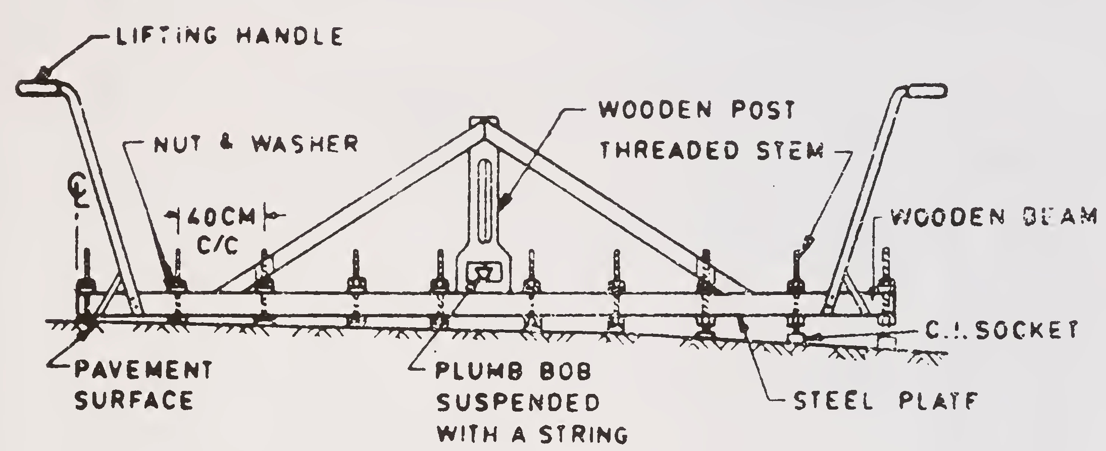
Fig. 1. One design of template adjustable profile
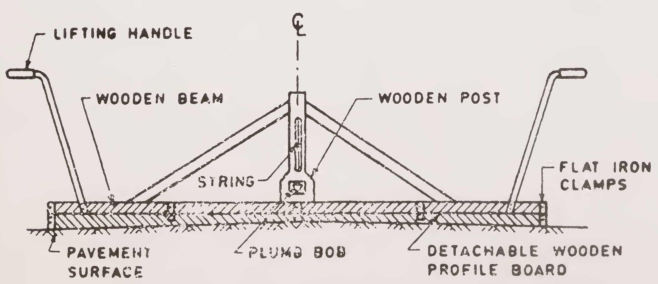
Fig. 2. Another design of template with adjustable profile77
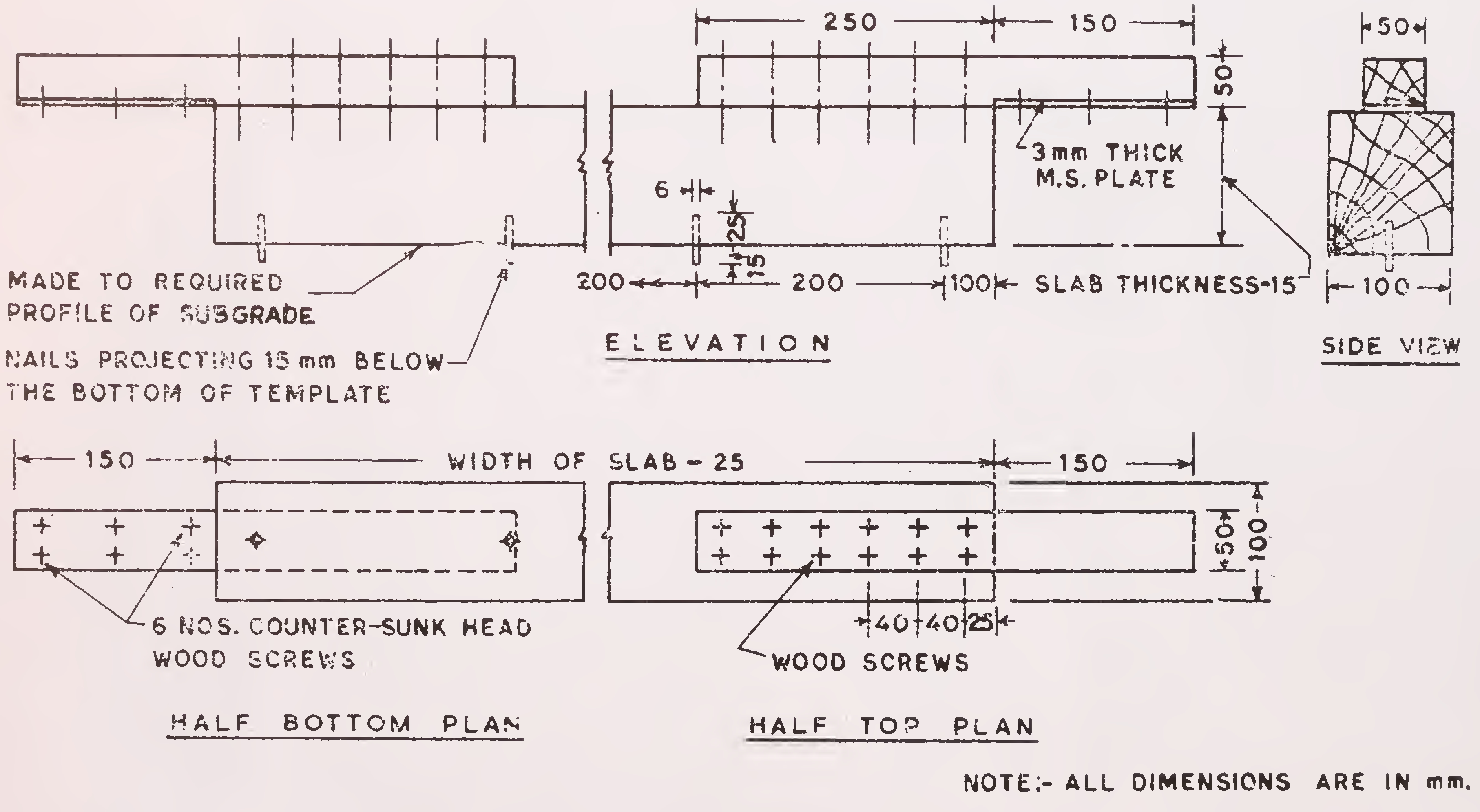
Fig. 3. Design of scratch template78
Evenness of Highway Pavements”) are indicated in Table 7.1. The various existing standards of the Indian Roads Congress are being revised on the basis of these recommendations. During construction, the surface evenness should be controlled as explained in paras 7.6. and 7.7.
| SI. No. | Type of Construction | Longitudinal Profile with 3 metre straight-edge | Cross Profile | |||||
|---|---|---|---|---|---|---|---|---|
| Maximum permissible undulation, mm | Maximum number of undulations permitted in any 300 metre length, exceeding mm | Maximum permissible variation from specified profile under camber template, mm | ||||||
| 18 | 16 | 12 | 10 | 6 | ||||
| 1 | 2 | 3 | 4 | 5 | 6 | 7 | 8 | 9 |
| 1. | Earthen subgrade | 24 | 30 | — | — | — | — | 15 |
| 2. | Stone soling Brick soling | 20 | — | 30 | — | — | — | 12 |
| 3. | Stabilised soil | 15 | — | — | 30 | — | — | 12 |
| 4. | Water Bound Macadam with oversize metal (40-90 mm size) | 15 | — | — | 30 | — | — | 12 |
| 5. | Water Bound Macadam with normal size metal (20-50 mm and 40-63 mm size), Penetration macadam or BUSG ** |
12 | — | — | 30 | — | 8 | |
| 6. | Surface dressing (two coat) over WBM (20-50 mm or 40-63 mm size metal), Penetration macadam or BUSG | 12 | — | — | — | 20 | — | 8 |
| 7. | Open graded premix carpet 20-25 mm thick | 10 | — | — | — | — | 30 | 6 |
| 8. | Bituminous macadam | 10 | — | — | — | — | 20@@ | 6 |
| 9. | Asphaltic Concrete | 8 | — | — | — | — | 10@@ | 4 |
| 10. | Cement Concrete | 8 | — | — | — | — | 10@@ | 4 |
|
Notes :
| ||||||||
The checking of transverse profile should commence right from the subgrade level and continued for each successive layer upto the top. Checking is done with the help of camber boards/templates, a few typical designs of which are shown in Figs. 1,2 and 3.
The template in Fig. 1, has adjustable reference pods so that the template can be pre-set for any desired profile. Fig. 2, shows a template in which the bottom piece for checking is replaceable to correspond to the specified profile. These designs are meant usually for checking the profile over a single-lane width. For two-lane or multi-lane roads, generally the checking operations will require to be carried out individually for each lane. Fig. 3, depicts a design of the scratch template used for checking the regularity of the base for concrete pavements.
For obtaining correct transverse profile on the finished surface of a layer, it is necessary that the spread material (before compacting/finishing) should conform to the desired profile as far as possible. Therefore, the profile of the spread material should be continuously regulated with template/camber boards (placed perpendicular to the road centre line). Normally, a set of three templates should be used in series at an interval of about 10 metres. Checking of the finished surface subsequently should be on the same lines. Additional checks may be made where visual appearance suggests an excessive variation.
The longitudinal evenness is specified in terms of the maximum permissible irregularity under a 3 metre straight-edge. Typical designs for a metallic straight-edge and measuring wedge are given in, Fig. 4. The checking of surface evenness must also commence right from the subgrade level.
The procedure to be followed for making surface unevenness measurements with a straight-edge is given at Appendix 6.
Straight-edge measurements are slow and rather tedious. Travelling and rolling type of straight-edges as well as other80
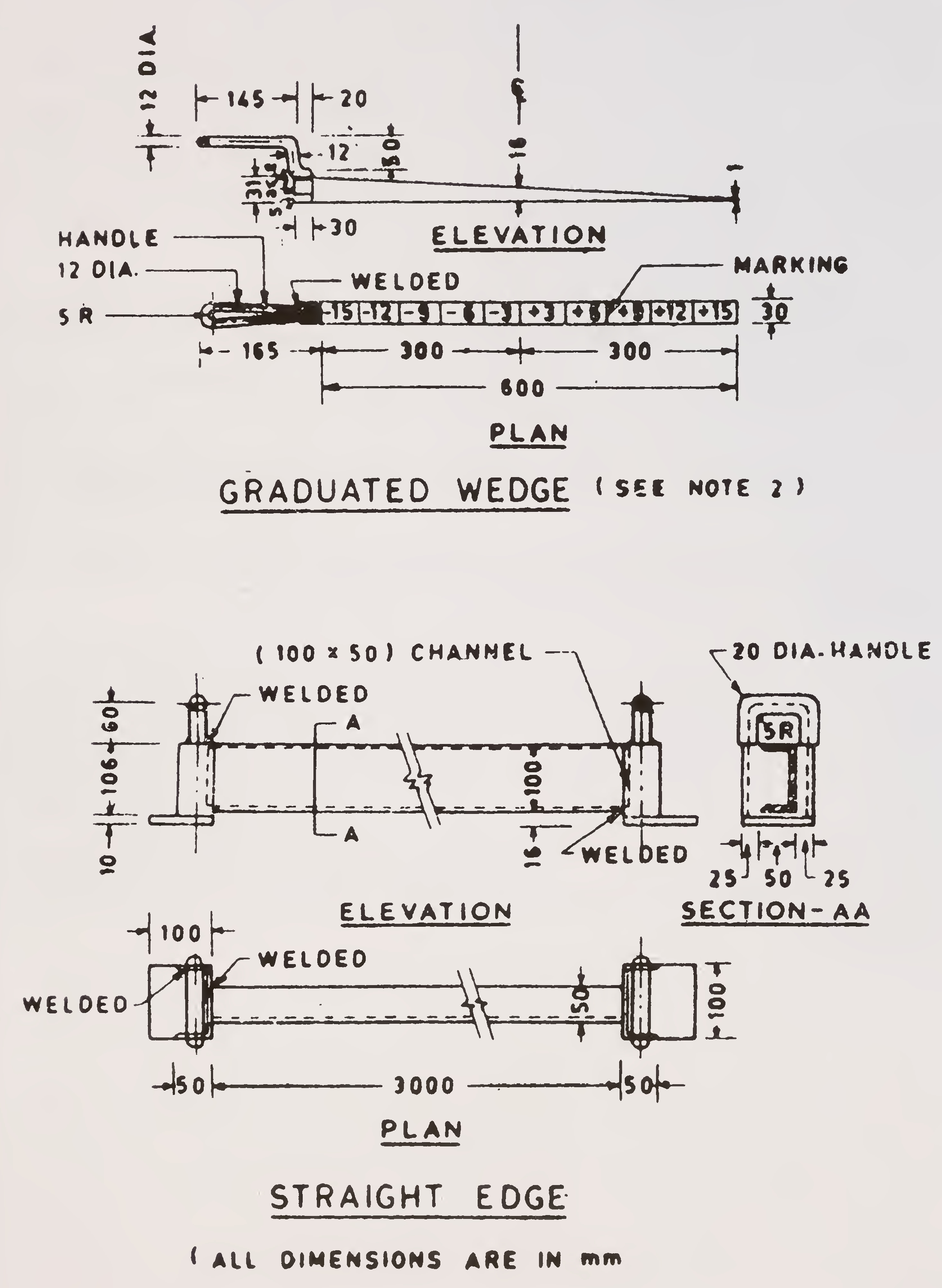
Note : In this design of the wedge, graduations are marked upto 15 mm. For measurements on subgrade and sub-bases, where variations are larger, a modified wedge with graduations upto 25 mm should be employed.
Fig. 4. Typical design of straight edge and wedge81
improved devices have been developed in some other countries for facilitating the work on control of surface evenness. A device available in India for this purpose is the Unevenness Indicator developed at the Central Road Research Institute. This is a travelling straightedge type of device which, when pre-set according to the specification for the surface under check, performs the following functions on being run by two workmen along the lines of measurement at a walking speed of about 5 km per hour :
The unit is simple to operate and is now readily available in the market. This should be used wherever possible.
The criteria in columns 4 to 8.........of Table 7.1. are meant to ensure that there are not too many irregularities of a size one lower than the permissible maximum. This check is exercised by counting the related irregularities as they occur and then seeing whether there is excessive occurrence over any 300 m length. Each depression/hump is to be counted only once. Both straight-edge and Unevenness Indicator methods are amenable to exercising of this control.82
It is to be appreciated that the road and runway construction, like most other construction process, has certain amount of variability inherent in the materials and methods involved. It will thus be prohibitively expensive and rather impracticable to have acceptance criteria for quality in such absolute terms as would imply the rejection of a piece of construction or a material on the basis of single sub-standard sample. Because of the inherent variability, the aim of quality control is to limit this variability as much as practicable. The acceptance criteria are thus required to be based on statistical evaluations so that they are not only realistic, but restrictive and as required by the design and performance requirements of the structure.
The statistical evaluations of the quality data provide a scientific analysis of the entire production process with respect to quality. They not only point out the general trends in the quality variations but also many a time go to expose the unsuspected causes of variation and thus lead to a striking improvement in constructional quality.
Arithmetic mean (also referred to as the average) is the sum of observations (strength results, say) divided by their number:

Standard deviation is an average of the deviations of the observations from their mean. This is defined as the square root of variance which is the mean square deviation from the true
mean value. Standard deviation is given by :

A more convenient formula, as given below is, however, generally used :

Co-efficient of variation is the standard deviation expressed as a percentage of the mean :

Range is the difference between the largest and the smallest values of the observations in the set :

| Notations: | |||
| X | = | any value in the set | |
| n | = | number of values of observations in the set | |
| x̄ | = | arithmetic mean | |
| j | = | standard deviation | |
| i | = | coefficient of variation | |
| R | = | range | |
Normal Distribution Curve and Control Limits
It has been established that when values from a large number of tests are considered for any of the tests on concrete in general, and its strength in particular, they conform to the Normal Gaussion Distribution Curve, Fig. 5, the spread of which, for all practical purposes, may be taken as 3 times the standard deviation on either side of the mean value.
The value which will have only a specified number (1 in N) or percentage (p%)—termed as tolerance level—of test data falling below it, is given by xmin—(x—rj), where r is a factor dependent upon the specified tolerance level.
The values of r for various tolerance levels are given in Table 8.1.86
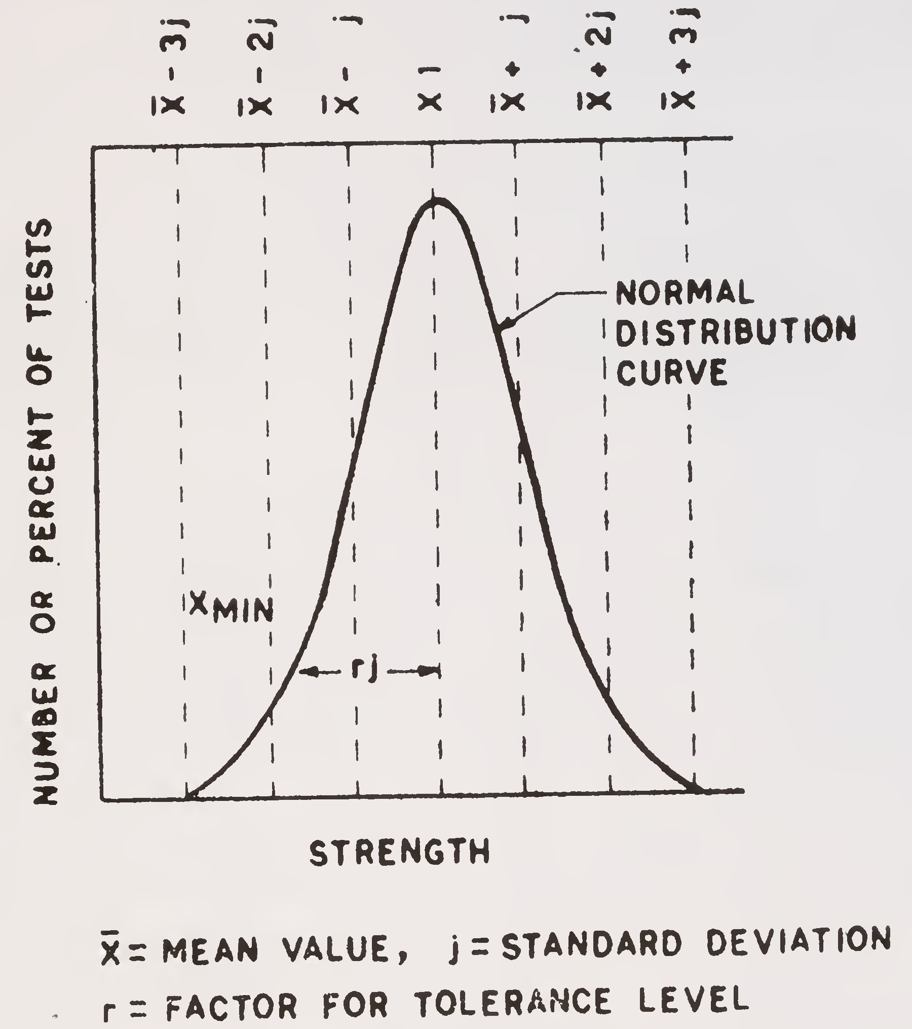
Fig. 5. Normal distribution curve
Conversely, for a specified minimum strength requirement xmin with a given tolerance level (and hence r), the average value x̄ for mix design strength has to be at least x̄=xmin+rj. The magnitude of standard deviation j is a function of the extent of uniformity achieved in quality of the product.
While the desired quality of the product is defined by xmin and r, the level of quality achieved is assessed from a knowledge of x̄, j and r. (x̄—rj) and (x̄ + rj) are termed as the lower control limit (L.C.L.) and the upper control limit (U.C.L.) respectively. When the stipulated specification requirements are satisfied L.C.L.⋟xmin.
A quality control progress chart (see Fig. 6 for a specimen) is the progressive plot of the desired test values, e.g.,87
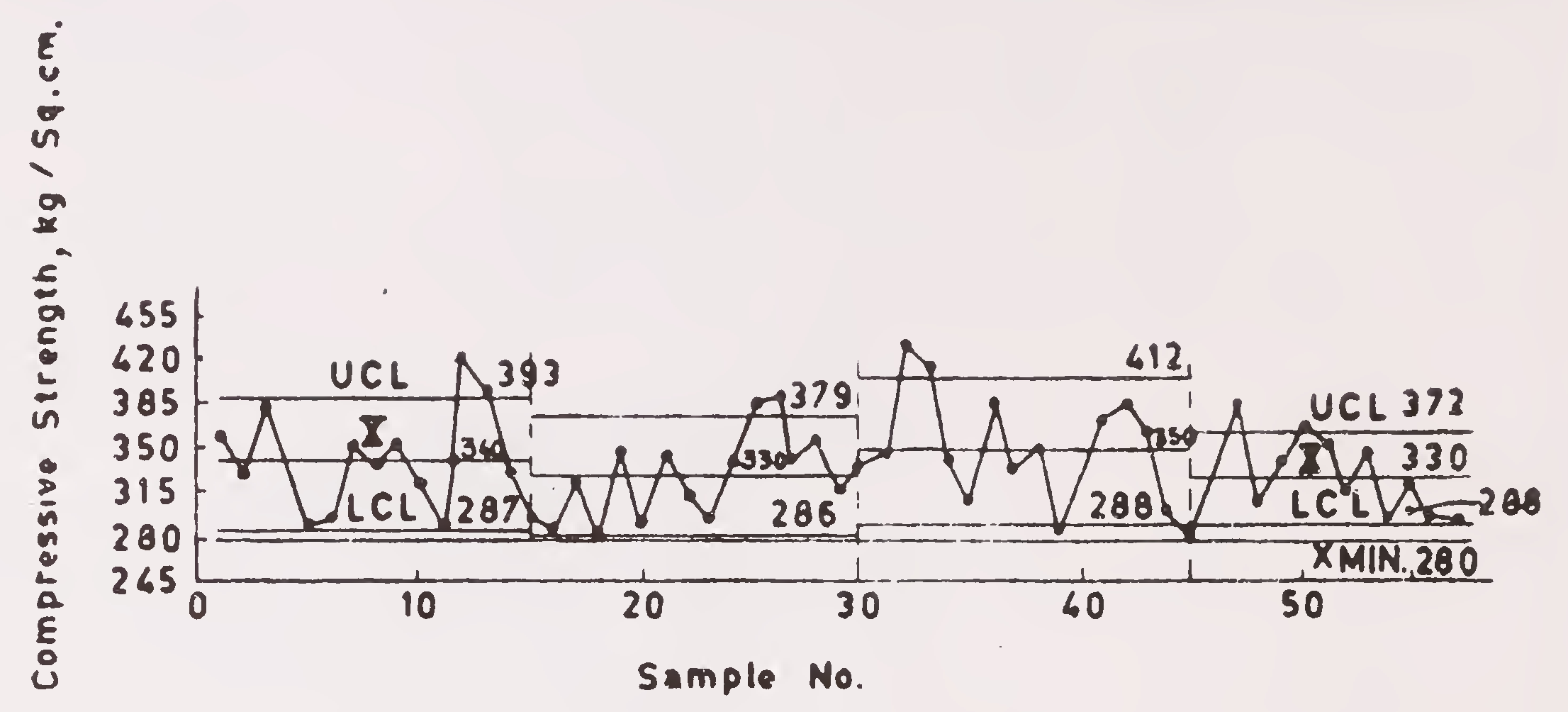
Fig. 6. Progress chart for strength test data
strength, against the serial number of sample tested. To obtain a general idea of the average variation in quality, the moving average of five tests which for any sample is the average of the five consecutive tests (including the sample under reference and four immediately preceding it) is also plotted on the chart. The x, U.C.L. and L.C.L. for stipulated number of samples as well as the specified xmin are also drawn. The progress chart enables seeing at a glance whether the desired quality is being achieved or not.
| Confidence level in terms of extent of test values that can be tolerated below the specified minimum value | r* |
|---|---|
| 1 in 3.20 (31%) | 0.5 |
| 1 in 6.25 (16%) | 1.0 |
| 1 in 10.00(10%) | 1.28 |
| 1 in 15.40 (6.5%) | 1.5 |
| 1 in 40.00 (2.5%) | 2.0 |
| 1 in 100.00(1.0%) | 2.33 |
| 1 in 666.00 (0.15%) | 3.00 |
| *Corresponds to infinite number of samples and appropriate for application to major concreting jobs. For small number of samples r value could be found in standard reference books, for example IRC: 44-1972. | |
The data for the 28 day compressive strength of concrete cubes from a construction project are given in Table 8.2.88
(columns 1 and 2). The minimum specified concrete strength xmin on the project was 280 kg/sq. cm, with a tolerance level of 1 in 10 (r= 1.28).
| S. No. | Compressive strength kg/sq. cm
x |
Moving average of 5 consecutive strength results kg/sq. cm | Deviation (x—x̄) kg/sq. cm |
(x—x̄)2 |
|---|---|---|---|---|
| 1 | 2 | 3 | 4 | 5 |
| 1. | 360 | 20 | 400 | |
| 2. | 330 | —10 | 100 | |
| 3. | 385 | 45 | 2025 | |
| 4. | 340 | — | — | |
| 5. | 290 | 330 | —50 | 2500 |
| 6. | 295 | 310 | -45 | 2025 |
| 7. | 350 | 330 | 10 | 100 |
| 8. | 340 | 320 | — | _ |
| 9. | 350 | 330 | 10 | 100 |
| 10. | 320 | 330 | —20 | 400 |
| 11. | 280 | 330 | —60 | 3600 |
| 12. | 420 | 340 | 80 | 6400 |
| 13. | 400 | 350 | 60 | 3600 |
| 14. | 330 | 350 | — 10 | 100 |
| 15. | 295 | 350 | —45 | 2025 |
| 16. | 290 | 350 | —50 | 2500 |
| 17. | 325 | 330 | —15 | 225 |
| 18. | 275 | 3.00 | -65 | 4225 |
| 19. | 350 | 310 | 10 | 100 |
| 20. | 280 | 300 | -60 | 3600 |
| 21. | 345 | 320 | 5 | 25 |
| 22. | 315 | 310 | —25 | 625 |
| 23. | 295 | 320 | -45 | 2025 |
| 24. | 340 | 310 | — | _ |
| 25. | 385 | 340 | 45 | 2025 |
| 26. | 400 | 350 | 60 | 3600 |
| 27. | 340 | 350 | — | _ |
| 28. | 360 | 370 | 20 | 400 |
| 29. | 315 | 360 | —25 | 625 |
| 30. | 340 | 350 | — | _ |
| 31. | 345 | 340 | 5 | 25 |
| 32. | 440 | 360 | 100 | 10000 |
| 33. | 420 | 370 | 80 | 6400 |
| 34. | 340 | 370 | — | _ |
| 35. | 310 | 370 | —30 | 900 |
| 36. | 385 | 380 | 45 | 2025 |
| 37. | 330 | 360 | —10 | 100 |
| 38. | 350 | 340 | 10 | 100 |
| 39. | 280 | 330 | -60 | 3600 |
| 40. | 330 | 340 | — 10 | 100 |
| 41. | 370 | 330 | 30 | 900 |
| 42. | 385 | 340 | 45 | 202589 |
| 43. | 365 | 350 | 25 | 625 |
| 44. | 300 | 350 | —40 | 1600 |
| 45. | 280 | 340 | -60 | 3600 |
| 46. | 330 | 330 | —10 | 100 |
| 47 | 385 | 330 | 45 | 2025 |
| 48. | 300 | 320 | —40 | 1600 |
| 49. | 340 | 330 | — | — |
| 50. | 370 | 340 | 30 | 900 |
| 51. | 360 | 340 | 20 | 400 |
| 52. | 315 | 330 | -25 | 625 |
| 53. | 345 | 340 | 5 | 25 |
| 54. | 295 | 330 | —45 | 2025 |
| 55. | 320 | 330 | -20 | 400 |
| 56. | 295 | 310 | -45 | 2025 |
| 57. | 295 | 310 | -45 | 2025 |
| ∑x = 19220 | ∑(x-x̄)2=87505 | |||
(1) Check whether the stipulated specification requirements are being met
Tabulation of data for the calculation of various statistical parameters is shown in Table 8.2.
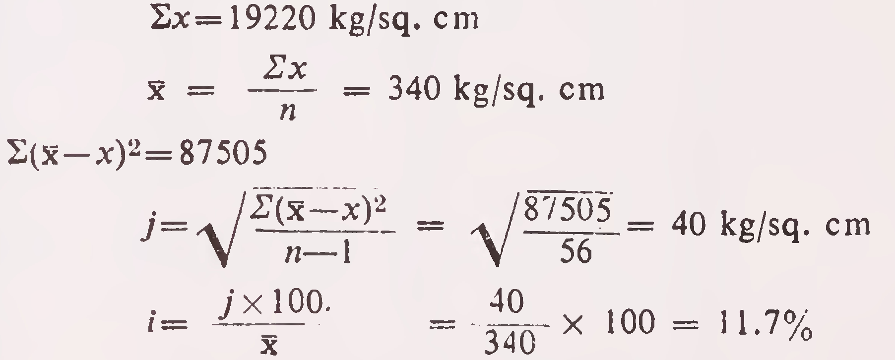
L.C.L. = x̄— rj = 340—1.28×40 = 288.8 kg/sq. cm
As L.C.L.>×min the specification requirements are met.
(2) Calculate the tolerance level actually achieved for the specified concrete

Therefore the tolerance level is 1 in 15.40 (Table 8.1.).
(3) Construct a quality control progress chart with this data
The Progress Chart is shown in Fig. 6.90
Table 8.3. shows the aggregate gradation data for the project. Both the stipulated aggregate gradation required to be achieved with a confidence level corresponding to r = 2, and the results of gradation tests run on aggregate samples are shown in this table.
(1) Check whether the stipulated
specification requirements are being met
Step I. For each sieve size, calculate x̄, j, L.C.L. and U.C.L. individually.
| L.C.L. | = | x̄—rj |
| U.C.L | = | x̄+rj |
This data is also tabulated in Table 8.3.
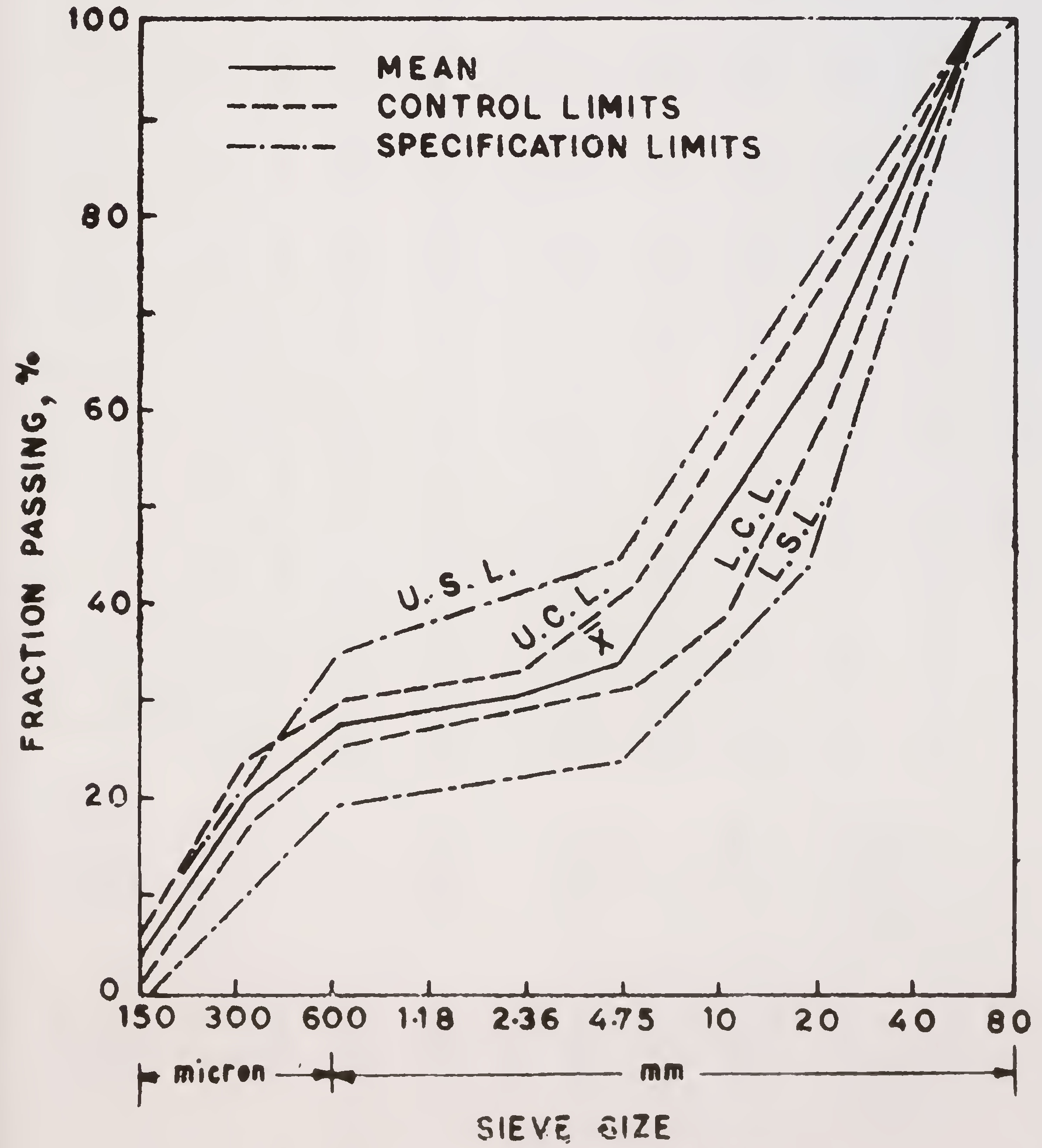
Fig. 7. Control chart for aggregate grading91
| I.S. Sieve size | Specification limits (% passing) | Sieve analysis (% passing, x) for test samples | ||||||||||||||
|---|---|---|---|---|---|---|---|---|---|---|---|---|---|---|---|---|
| (1) | (2) | (3) | (4) | (5) | (6) | (7) | (8) | (9) | (10) | (11) | (12) | (13) | (14) | (15) | ||
| 50 mm | 95—100 | 100 | 100 | 100 | 100 | 100 | 100 | 100 | 100 | 100 | 100 | 100 | 100 | 100 | 100 | 100 |
| 40 mm | — | 86.1 | 85.9 | 84.2 | 85.5 | 81.5 | 85.4 | 85.1 | 84.8 | 85.3 | 83.5 | 82 6 | 83.7 | 84.2 | 82.9 | 81.9 |
| 20 mm | 45—75 | 71.2 | 66.7 | 64.3 | 61.9 | 64.9 | 68.0 | 68.1 | 65.1 | 64.1 | 59.4 | 62.7 | 60.7 | 57.5 | 68.2 | 69.2 |
| 10 mm | — | 55.4 | 49.5 | 47.8 | 47.5 | 53.9 | 50.3 | 54.4 | 42.0 | 48.0 | 53.4 | 50.1 | 46.9 | 42.0 | 48.1 | 54.7 |
| 4.75 mm | 25—45 | 38.0 | 36.6 | 35.8 | 37.0 | 39.0 | 35.3 | 38.8 | 33.1 | 35.6 | 36.1 | 38.3 | 35.4 | 33.8 | 33.8 | 38.5 |
| 2.36 mm | — | 32.2 | 33.0 | 31.5 | 32.6 | 32.3 | 32.3 | 32.5 | 32.4 | 32.5 | 33.2 | 33.1 | 30.8 | 32.0 | 30.2 | 33.7 |
| 1.18 mm | — | 30.4 | 30.5 | 28.9 | 29.7 | 29.0 | 30.2 | 30.6 | 31.5 | 30.7 | 30.9 | 30.5 | 28.0 | 30.7 | 28.0 | 31.0 |
| 600 micron | 20-30 | 28.4 | 28.6 | 26.9 | 27.5 | 27.4 | 28.3 | 28.6 | 30.7 | 29.5 | 28.6 | 28.4 | 26.4 | 29.0 | 26.1 | 29.7 |
| 300 micron | — | 19.6 | 19.2 | 18.6 | 20.1 | 19.3 | 20.7 | 19.7 | 24.7 | 22.9 | 20.4 | 20.5 | 19.5 | 21.2 | 18.6 | 23.3 |
| 150 micron | 0-6 | 2.4 | 2.7 | 2.9 | 5.7 | 3.0 | 3.7 | 5.7 | 4.2 | 6.3 | 6.2 | 4.4 | 3.1 | 2.9 | 3.5 | 3.792 |
| I.S. Sieve size | Specification limits (% passing) | Sieve analysis (% passing, x ) for test samples | |||||||||||||
|---|---|---|---|---|---|---|---|---|---|---|---|---|---|---|---|
| (16) | (17) | (18) | (19) | (20) | (21) | (22) | (23) | (24) | (25) | x̄ | J U.C.L. x̄+2j |
L.C.L. x̄-2j | |||
| 50 mm | 95—100 | 100 | 100 | 100 | 100 | 100 | 100 | 100 | 100 | 100 | 100 | 100 | 0 | 100 | 100 |
| 40 mm | — | 82.2 | 86.2 | 87.1 | 85.6 | 84.3 | 83.1 | 82.6 | 84.0 | 83.8 | 87.8 | 84.4 | 1.6 | 87.6 | 81.2 |
| 20 mm | 15—75 | 70.2 | 64.1 | 67.2 | 64.2 | 65.9 | 68.8 | 68.9 | 61.2 | 68.2 | 65.0 | 65.4 | 2.5 | 72.4 | 58.4 |
| 10 mm | — | 60.0 | 47.8 | 50.7 | 42.9 | 42.0 | 52.8 | 39.2 | 43.9 | 50.2 | 43.2 | 48.7 | 5.1 | 58.9 | 38.5 |
| 4.75 mm | 25—45 | 40.5 | 34.6 | 37.1 | 33.7 | 32.0 | 36.2 | 32.6 | 33.6 | 35.3 | 32.4 | 35.7 | 2.3 | 40.3 | 31.1 |
| 2.36 mm | — | 32.6 | 31.7 | 31.3 | 31.0 | 30.3 | 31.9 | 30.4 | 30.5 | 31.5 | 30.6 | 31.8 | 1.0 | 33.8 | 29.8 |
| 1.18 mm | — | 28.6 | 30.0 | 28.8 | 29.1 | 28.8 | 30.2 | 28.2 | 27.2 | 29.8 | 28.8 | 29.6 | 1.1 | 31.8 | 27.4 |
| 600 micron | 20-30 | 27.1 | 28.7 | 27.3 | 27.6 | 27.4 | 29.1 | 26.6 | 24.7 | 28.6 | 27.0 | 27.9 | 1 3 | 30.5 | 25.3 |
| 300 micron | — | 19.4 | 21.3 | 17.2 | 18.6 | 18.9 | 17.7 | 21.4 | 18.2 | 16.1 | 17.2 | 19.8 | 2.0 | 23.8 | 15.8 |
| 150 micron | 0—6 | 2.7 | 2.2 | 1.2 | 2.2 | 1.9 | 2.0 | 4.7 | 4.5 | 2.0 | 1.7 | 3.4 | 1.6 | 6.6 | 0.293 |
Step II. On a plot of the stipulated gradation zone, plot x̄. In case x̄ lies within the zone, plot L.C.L. and U.C.L., as well. If both L.C.L. and U.C.L. lie within the stipulated zone, the specification is being met. The actual plot is shown in, Fig. 7. It is seen that the specification requirements are being met, except for sieve Nos. 300 and 600 micron for which U.L.C. does not lie within the stipulated zone.94
Appendix 1
LIST OF STANDARD SPECIFICATIONS OF INDIAN ROADS CONGRESS REFERRED TO IN THE TEXT
| Number of Standard | Title |
| IRC : 14-1977 | Recommended, practice for 2 cm thick bitumen and tar carpets (First Revision) |
| IRC : 15—1981 | Standard specifications and code of practice for construction of concrete roads (First Revision) |
| IRC : 17—1965 | Tentative specification for single coat bituminous surface dressing |
| IRC : 19—1977 | Standard specifications and code of practice for water bound macadam (First Revision) |
| IRC : 20—1966 | Recommended practice for bituminous penetration macadam (full grout) (First Revision) |
| IRC : 23-1966 | Tentative specification for two coat bituminous surface dressing |
| IRC : 27—1967 | Tentative specification for bituminous macadam (base and binder course) |
| IRC : 29—1968 | Tentative specification for 4 cm asphaltic concrete surface course |
| IRC : 36-1970 | Recommended practice for the construction of earth embankments for road works |
| IRC : 43—1972 | Recommended practice for tools, equipments and appliances for concrete pavement construction |
| IRC : 44—1976 | Tentative guidelines for cement concrete mix design for road pavements (For non—air entrained and continuously graded concrete) (First Revision) |
| IRC : 47—1972 IRC : 48-1972 | Tentative specification for built-up spray grout Tentative specification for bituminous surface dressing using precoated aggregates |
| IRC : 57-1974 | Recommended practice for sealing of joints in concrete pavements |
| IRC : 59—1976 | Tentative guidelines tor design of gap graded cement concrete mixes for road pavements |
| IRC : 61 — 1976 | Tentative guidelines for the construction of cement concrete pavements in hot-weather |
| IRC SP : 16—1977 | Surface evenness of highway pavements |
Appendix 2
LIST OF TEST STANDARDS OF BUREAU OF INDIAN STANDARDS AND OTHER BODIES REFERRED TO IN THE TEXT
| Number of Standard | Title |
| IS : 215—1961 | Road Tar (Revised) |
| IS : 217-1961 | Cutback Bitumen (Revised) |
| IS : 269—1967 | Ordinary, Rapid-hardening and Low Heat Portland Cement (Second Revision) |
| IS : 454-1961 | Digboi Type Cutback Bitumen (Revised) |
| IS : 455-1967 | Portland Blast Furnace Slag Cement (Second Revision) |
| IS : 456-1964 | Code of Practice for Plain and Reinforced Concrete (Second Revison) |
| IS : 460—1962 | Test Seives (Revised) |
| IS : 516—1959 | Methods of Test for Strength of Concrete |
| IS : 1199-1955 | Methods of Sampling and Analysis of Concrete |
| IS : 1203-1958 | Determination of Penetration (Procedure for testing tar and bitumen products) |
| IS : 1489—1967 | Portland-pozzolana Cement (First Revision) |
| IS : 1514—1959 | Methods of Sampling and Test for Quick Lime and Hyderated Lime |
| IS : 1834—1961 | Sealing Compounds, Hot applied for Joints in Concrete |
| IS : 2386 | Methods of Test for Aggregates for Concrete |
| (Part I)—1963 | Particle Size and Shape |
| (Part II)—1963 | Estimation of deleterious materials and Organic impurities |
| (Part III)—1963 | Specific Gravity, Density, Voids, Absorption and Bulking |
| (Part IV)—1963 | Mechanical Properties |
| (Part V)—1963 | Soundness |
| (Part VII)—1963 | 'Alkali-aggregate Reactivity' |
| IS : 2505—1968 | Concrete Vibrators, Immersion Type |
| IS : 2506—1964 | Screed Board Concrete Vibrators |
| IS : 2514—1963 | Concrete Vibrating Tables |
| IS : 2720 | Methods of Test for Soils |
| (Part II)—1973 | Determination of Water Content (Second Revision) |
| (Part IV)—1975 | Grain Size Analysis |
| (Part V)—1970 | Determination of Liquid and Plastic Limits (First Revision) |
| (Part VII)-1974 | Determination of Water Content-Dry Density Relation using Light Compaction |
| (Part VIII)—1974 | Determination of Water Content-Dry Density Relation using Heavy Compaction |
| (Part X)—1973 | Determination of Unconfined Compressive Strength (First Revision) |
| (Part XVI)—1965 | Laboratory Determination of C.B.R. |
| (Part XXVII)—1968 | Determination of Total Soluble Sulphates |
| (Part XXVIII)-1974 | Determination of Dry Density of Soils, in-place of Sand Replacement Method (First Revision) |
| IS : 3495-1973 | Method of test for Clay Building Bricks (First Revision) |
| IS : 4098-1967 | Lime—pozzolana Mixture |
| IS : 6241—1971 | Method of Test for Determination of Stripping Value of Road Aggregate |
| A STM.D-1138-1952 | Test for Resistance to Plastic Flow of Fine Aggregate Bituminous Mixtures by means of the Hubbard-Field Apparatus |
| ASTM D-1559—1965 | Test for Resistance to Plastic Flow of Bituminous Mixtures using Marshall Apparatus99 |
Appendix 3
CONSOLIDATED LIST OF EQUIPMENT TO BE PROVIDED IN THE STATE CENTRAL LABORATORIES
| S. No. | Equipments | Number required | |
| 1 | 2 | 3 | |
| A. | General Equipment | ||
| (i) High sensitivity proving ring | 100 kg —Capacity | 2 | |
| (ii) | 200 kg —Capacity | 2 | |
| (Hi) | 500 kg —Capacity | 2 | |
| (iv) | 1000 kg —Capacity | 1 | |
| (v) | 2000 kg —Capacity | 1 | |
| 2. | Dial Guages | ||
| (i) 12 mm Travel | .6 | ||
| (ii) 25 mm Travel | 6 | ||
| 3. | Balances | ||
| (i) 7 kg capacity—accuracy 1 gm | 1 | ||
| (ii) 500 gm capacity—accuracy 0.001 gm | 2 | ||
| (iii) Chemical Balance—100 gm. Accuracy 0.0001 gm | 1 | ||
| (iv) Pan balance—5 kg capacity | 1 | ||
| (v) Physical balance—0.001 gm accuracy | 2 | ||
| (vi) Platform scale—5 cwt. capacity | |||
| 4. | Ovens : Electrically operated, thermostatically controlled | ||
| (i) Upto 110°C-Sensitivity 1°C | |||
| (ii) Size 24" x 16" x 14" | 2 | ||
| (iii) Upto 400°F rotating type—Determination of loss on heating bitumen | 1 | ||
| 5. | Sieves | ||
| (i) B.S. Sieves—size—18" dia. 3", 2", 1½", ¾", 2" | 1 set | ||
| (ii) B.S. Sieves-8" dia. 7, 14, 25, 36, 52, 72, 100, 170 & 200 | 1 set | ||
| 6. | Sieve shaker capable of taking 8" and 12" dia. sieves— electrically operated with time switch assembly | 1 | |
| 7. | Proving Rings | ||
| (i) 400 lbs. capacity | 1 | ||
| (ii) 6000 lbs. capacity | 1 | ||
| (iii) 5 ton capacity | 1 | ||
| Note:All Indian testing equipment, instruments and materials shall conform to ISI specifications and shall bear, IS Markings, as far as possible. | |||
| 1 | 2 | 3 |
| 8. | Dial Guages | |
| (i) 1" travel—0.001" division | 6 | |
| (ii) 2" travel—0.001" division | 6 | |
| 9. | Load frame—5 ton capacity electrically operated with speed control | 1 |
| 10. | 200 ton compression testing machine | 1 |
| 11. | Stop watches 1/5 sec. accuracy | 3 |
| 12. | Glass ware | |
| 13. | Miscellaneous | |
| 14. | Hot plates 7" dia. | |
| B. | Sub-surface Investigations | |
| 1. | Truck | 1 |
| *2. | Drilling Rig. upto 60 m depth | 1 |
| 3. | Soil & rock drilling kit | 1 |
| 4. | Vane shear kit | 3 |
| *5. | Portable equipment for seismic survey (TERRASOOUT) | 1 |
| *6. | Stratometer for electrical resistivity survey | 1 |
| 7. | Borehole Camera | 1 |
| *8. | Binocular type micro scope | 1 |
| *9. | Borehole deformation meter | |
| 10. | Static penetrometer equipment (10 tonnes, | 1 |
| 11. | Hydraulic Jacks (30, 50, 100 and 200 tonnes) | 1 |
| 12. | Undisturbed soil samplers (Dension & Piston Sampler) | 1 |
| 13. | Plate load test equipment | 1 |
| 14 | Thin wall sampling tubes (100 & 50 mm dia. and 0.75 m long) | 100 each type |
| 15. | SPT Test equipment and static cone penotrometers | 3 |
| C. | Soils | |
| 1. | Watter Still | 1 |
| 2. | Liquid Limit device and tools | |
| 3. | Sampling pipette fitted with pressure and suction inlets, 10 ml. capacity | |
| 4. | B.S. compaction appratus (Proctor) | |
| *Optional items depending on the requirements.101 | ||
| 5. | Modified AASHO compaction apparatus | |
| 6. | Sand pouring cylinder with conical funnel and tap | |
| 7. | Capillary water absorption test equipment | |
| 8. | Sampling tins with lids 03" dia. x 21" ht. 1 lb. size—100 nos. and miscellaneous items like moisture tins, etc. | |
| 9. | PH meter | |
| 10. | Constant head & variable head permometer | |
| 11. | Unconfined compression test apparatus with a set of 4 springs and masks | |
| 12. | Lab. CBR test equipment with 12 moulds | |
| 13. | Field CBR test equipment | |
| 14. | Plate bearing test equipment with 12" dia. plate | |
| 15. | Shear box test equipment | |
| 16. | Triaxial compression test equipment | |
| 17. | Consolidation test equipment | |
| 18. | 5—ton capacity mechanical jack | |
| 19. | Post hole auger 4" dia. with extensions and Shelby tube for undisturbed sampling | |
| 20. | Truck chassis capable of loading, upto 8 tons | |
| 21. | Sample extractor frame with hydraulic jack hand operated | 1 |
| 22. | Motorised unconfined compression testing machine | 1 |
| 23. | Motorised direct shear operators with 12 rate of strain | 1 |
| 24. | Triaxial testing equipment (Motorised) with 8 rates of feed and assembly for lateral-pressure and pore pressure | 1 |
| 25. | Tor Vans Appratus | 3 |
| 26. | Universal Automatic Compactor | 1 |
| 27. | Core cutter | 6 |
| 28. | Soil lathe | 1 |
| 29. | Vaccum pump | 1 |
| 30. | Proctor needle (spring type) | 6 |
| *31. | Consolidation test equipment | 3 |
| D. | Bitumen | |
| 1. | Constant temperature bath | 1 |
| 2. | Petrol gas generator (laboratory model) | 1 |
| 3. | Ring & Ball softening point apparatus | |
| 4. | (BRTA) Viscometer with 4 mm and 10 mm cups | |
| 5. | Fngler viscometer for emulsions102 | |
| 6. | Red wood No. 1 and 2 viscometers | |
| 7. | Penetrometer automatic type, adjustable weight arrangement and needles | |
| 8. | Soxhlet extraction appratus type SJB 50 | |
| 9. | Moisture determination apparatus with still (copper) and other accessories | |
| 10. | Extraction thimbles 43 x 123 mm size | 30 |
| 11. | Laboratory mixer 1/2 cft. capacity, electrically operated fitted with heating jacket | |
| 12. | Ductibility testing apparatus with variable speed gears complete with moulds | |
| 13. | Moulds for Hubbard-Field stability test 6'' x 2" dia. | |
| 14. | Equipment for distillation of tars, cut-backs, etc. | |
| 15. | Hveem stabilometer | |
| 16. | Marshall compaction apparatus | |
| E. | Rock testing equipment | |
| 1. | Rock sample height guage | 1 |
| 2. | Rock classifaction hammer | 1 |
| 3. | Portable rock tester | 1 |
| *4. | Field direct shear kit | 1 |
| F. | Concrete and Structures | |
| 1. | Water still | 1 |
| 2. | Vicat needle appratus for setting time test with plungers | |
| 3. | Moulds | |
| (i) 4" x 4" x 20" | 12 | |
| (ii) Cubical 6", 4", 2.78" | 6 each size | |
| 4. | Lechatelier soundness testing apparatus | |
| 5. | Air permeability apparatus | |
| 6. | High frequency mortar cube vibrator | 1 |
| 7. | Concrete mixer power driven 1 cft. capacity Concrete mixer power driven 5 cft. capacity | 1 1 |
| 8. | Variable frequency and amplitude vibrating Table size 2" x 3" load 200 lbs. | |
| 9. | Aggregate crushing test apparatus | |
| 10. | Aggregate impact test apparatus | |
| 11. | Los-Angles abrasion apparatus | |
| 12. | D-val attribution apparatus103 | |
| 13. | Flexural attachement to compression testing machine | |
| 14. | Concrete laboratory set up | 1 |
| 15. | In-situ concrete strength testing equipment, test hammer & pachometer | 1 |
| 16. | UTM for tension, compression and other tests | 1 |
| 17. | Strain measuring equipment set | 1 |
| G. | Equipment for Hydraulic Studies | |
| 1. | Current meter | 1 |
| 2. | Echo sounding equipment | 1 |
| H. | Road Testing Equipment | |
| 1. | Benkelman Beam | 2 |
| 2. | Profile meter (hand towed) | 2 |
| *3. | British portable skid tester | 4 |
| *4. | Accelerated polishing machine | 1 |
| I. | Traffic Engineering | |
| *1. | Radar speed meter | 1 |
| 2. | Enoscope | 1 |
| *3. | Electronic traffic counter | 1 |
| 4. | Multi-bank event recorder | 6 |
| *5. | Multi-pen event recorder | 1 |
| 6. | Time lapse photography camera and projector unit | 1 |
| J. | Terrain Evaluation and Photography | |
| * j | Pocket stereoscope | 2 |
| *2. | Stereoscope with Parallex Bar | 1 |
| K. | Mobile Laboratory | |
| *1. | Laboratory Truck | 1 |
| *2. | Equipment | 1 |
| L. | Special Research Equipment | |
| *1. | Equipment. (individual items should be identified | |
| depending on actual needs) | 1 | |
| M. | Quality Control Equipment in Field | |
| *1. | Equipment (individual items to be identified depending on actual needs) | 1 |
| N. | Miscellaneous | |
| 1. | Electronic Desk Calculator | 1 |
| *2. | Slide Projector | 1 |
| *3. | Camera | 1 |
| *4. | Photostat Machine | l104 |
STATEMENT SHOWING THE RANGE OF ADDITIONAL EQUIPMENT PROPOSED BY SOME OF THE STATES FOR AUGMENTING THEIR CENTRAL LABORATORIES
| S. No. | Discipline | Additional Equipment |
| 1 | 2 | 3 |
| 1. | Soils | Dynamic cone penetrometer; soil lathe Flash shaker; Grimilaboratory blender; Winkworth laboratory mixer; Dieter’s compaction apparatus; speedy moisture tester; conductivity bridge; electrical earth pressure apparatus; sand equivalent test apparatus; soil density probe with utility seater; automatic compaction machine; platform vibrator with relative density kit; rotary high vaccum pump; Genco presso-vac pump; mechanical stirrer; mechanical mixer; shrinkage factor apparatus; Proctor needle; Abbot’s cylinder; calcimeter; soil centrifuge apparatus; sand equivalent test apparatus; vane shear apparatus; PVC meter. |
| 2. | Bitumen | Distillation apparatus: electro-hydraulic kneading compactor; float test apparatus; settlement ratio appratus; new model versa tester; Higler speaker absorption meter; barometer; Gilson testing screen and accessories; Kipp’s apparatus; hydro vapourising unit. |
| 3. | Concrete and Bridges | Prestressing bed; jack and other equipments, concrete coring equipment; beam breaker concrete test hammer; twisting machine; Universal testing machine; boring plant; supersonic tester; Acrow weighmore consistometer; drying shrinkage apparatus B.T.L. oven; muffle furnace; internal vibrator; shutter vibrator; masonry saw; briquette testing machine; K.C.P. tensile testing machine; fatigue tester; cold bend test; Askamia vibrator; |
| 4. | Aggregates | Dorry’s attrition test; Stewart’s impact test; Page impact test; jaw crusher slitting, grinding and polishing machine. |
| 5. | Traffic | Electronic traffic counter; electric speed meter; Skyke’s vehicle counter; enoscope wheel weigher; brake inspection decelero-meter; instrument for tracing track width of curves; hand tally counter. |
| 6. | Road Testing | Benkelman beam; bump integrator; immersion tracking machine; skid resistance tester electronic roughness tester.105 |
| 7. | Photographic/ sound equipment | Photometer; lux meter; recording camera; super cameras; enlarger; movie camera; sound projector; slide projector; epidiascope ; amplifiers; photostat machine. |
| 8. | Electric/ Electronic and other miscellaneous equipment | Polarising microscope; electronic weighing machine; generator; oscilloscope; vibration pick up; excitation amplifier; strain measuring bridge; oscolo script; G.K. Varistant; electronic calculator; duplicating machine; pallet trucks; mobile van; gas generator; electric tube, furnace, cassette tape recorder; refrigerator, analytical and other preicsion balances. |
TESTING EQUIPMENT REQUIRED FOR SETTING OF REGIONAL LABORATORY
| S. No. | Particulars of Equipment | Nos. required |
| 1. | GENERAL | |
| I. | Balances: | |
| (i) 7 kg to 10 kg capacity-semi-self indicating type — Accuracy 1 gm | 2 | |
| (ii) 500 gm capacity-semi-self indicating type-Accuracy 0.001 gm | 2 | |
| (iii) Chemical Balance-100 gm capacity-Accuracy 0.0001 gm | 1 | |
| (iv) Pan Balance — 5 kg capacity | 3 | |
| (v) Physical Balance — 0.001 gm accuracy | 3 | |
| (vi) Platform scale — 300 kg capacity | 1 | |
| 2. | Ovens - Electrically Operated, Thermostatically Controlled : | |
| (i) Upto 110°C — Sensitivity I.C. | 1 | |
| (ii) Upto 200°C — for determination on loss on heating bitumen | 1 | |
| 3. | Sieves : as per I.S. 460-1962 : | |
| (i) I.S. Sieves — 450 mm internal dia. of sizes 100 mm, 80 mm, 63 mm, 40 mm, 25 mm, 20 mm, 12.5 mm, 10 mm, 6.3 mm, 4.75 mm complete with lid and pan | 1 set | |
| (ii) I.S. Sieves — 200 mm internal dia (brass frame) consisting of 2.36 mm, 1.18 mm, 600 microns, 425 microns, 300 microns, 212 microns, 150 microns, 90 microns and 75 microns with lid and pan | 1 set106 | |
| 4. | Sieve shaker capable of taking 200 mm and 300 mm dia, sieves-electrically operated with time switch assembly | 1 No. |
| 5. | Proving rings - complete with dia guage and calibration charts : | |
| (i) 250 kg capacity | 2 | |
| (ii) 2000 kg capacity | 2 | |
| (iii) 5 tonnes capacity | 2 | |
| 6. | Dial Guage | |
| (i) 25 mm travel-0.01 mm/division | 2 Nos. | |
| 7. | Load frame-5 tonnes capacity electrically operated | |
| with speed control | 1 | |
| 8. | 200 tonnes compression testing machine | 1 |
| 9. | Stop watches 1/5 sec. accuracy | 4 |
| 10. | Glassware comprising Brakers, Pipettes, dishes, measuring cylinders (100 to 1000 cc capacity) rods & funnels | 1 doz. each |
| 11. | Hot plates 200 mm dia. (1 no 1500 watt) | 2 Nos. |
| 12. | Enamel trays | |
| (i) 600 mm x 450 mm x 50 mm | 6 | |
| (ii) 450 mm x 300 mm x 40 mm | 6 | |
| (iii) 300 mm x 250 mm x 40 mm | 6 | |
| (iv) Circular plates of 250 mm dia | 6 | |
| SOILS | ||
| 1. | Water still | 1 No. |
| 2. | Liquid limit device with Casagrande and A.S.T.M grooving tools and as per I.S. 2720-Part V-1970 | 2 |
| 3. | Sampling pipette fitted with pressure and suction inlets, 10 ml. capacity | _ |
| 4. | Compaction apparatus (Proctor) as per l.S. 2720 Part V11-1974 | 2 |
| 5. | Modified AASHO compaction apparatus as per I.S. 2720-Part VIII-1974 | 1 |
| 6. | Sand pouring cylinder with conical funnel and tap and complete as per I.S. 2720 Part XXVIII-1974 | 1 doz. |
| 7. | Sampling tins with lids 100 mm dia x 50 mm ht. 1/2 kg capacity—and miscellaneous items like moisture tins, etc. | 2 doz. |
| 8. | Unconfined compression test apparatus with a set of 4 springs and masks and complete as per I.S. 2720 Part X-1974 | 1107 |
| 9. |
Lab C.B.R. test equipment for conducing CBR test as per I.S. 2720-Part XVI-1965 and consisting of following : (i)CBR moulds 150 mm dia. 175 mm ht, complete with collar, base plate, etc (ii)Tripod stands-for holding dial guage holder (iii)C.B.R. plunger with settlement dial guage holder (iv)Surcharge weight 147 mm dia. 2.5 kg wt. with central hole. (v)Spacer discs 148 mm dia., 47.7 mm ht. with handle (vi)Perforated plate (Brass) (vii)Soaking tank for accommodating 6 CBR moulds each | |
| 10. | Field C.B.R. test equipment consisting of hand operated mechanical jack of 5 tonnes capacity, capable for sliding on I section fixable to truck chassis, proving ring of 2000 kg capacity, extension pieces (of adjustable length upto 1 metre length), CBR Plunger, settlement dial guage holder, datum bar, 254 mm (10 in) dia. surcharge wt. with central hole (47.7 mm dia) and 4.53 kg (10 lb)-2 nos. and 9.07 kg (20 lb)-2 nos. and one I-section of 1.25 metre length having arrangement of clamping to truck chassis | 1 set |
| 11. |
Plate bearing test equipment consisting of following items : (i)M.S plates 25.4 mm (1 in thick and dia 762 mm (30 in.) 660 mm (26 in.) 558 mm (22 in.) 457 mm (18 in.) 305 mm (12 in.) 228 mm (9 in.) and 154 mm (6 in.) (ii)Hydraulic jack 20 tonnes capacity with remote control through flexible tubing of 2-3 metre length iii) Proving ring 25 tonnes capacity with dial guage and calibration chart (iv) Ball bearing plates 25 mm thick and 100 mm dia. with centre groove (v) Datum Bar 3 metre long with stand and dial guage clamps (2 nos.) with suitable attaching arrangements | 1 set |
| 12. | Standard Penetration test equipment | 2 Nos. |
| 3. BITUMEN | ||
| 1. | Constant temperature bath for accommodating bitumen test specimen, electrically operated and thermostatically controlled. | 1108 |
| 2. | Petrol gas generator (Laboratory model or any other alternative arrangement for heating of specimens in laboratory) | 1 |
| 3. | Penetrometer automatic type, adjustable weight arrangement, and needles as per I.S. 1203-1958. | 1 |
| 4. | Soxhlet extraction apparatus complete with extraction thimbles, etc. | |
| 5. | Laboratory mixer about 0.02 cu. metre capacity electrically operated fitted with heating jacket | 1 |
| 6. | Hubbard-field stability test apparatus complete | 1 |
| 7. | Marshall compaction apparatus as per ASTM 1559-62 T and complete with electrically operated loading unit, compaction pedestal hearing head assembly, dial micrometre and bracket for flow measurement, load transfer bar, specimen mould (4 in. dia) with base plate, collars, specimen extractor, compaction hammer 4.53 kg. (10 lb)x 457 mm (18 in.) fall | 1 |
| 8. | Distant reading thermometers | i |
| CONCRETE AND MATERIALS | ||
| 1. | Water still | |
| 2. | Vicat needle apparatus for setting time test with plungers, as per I.S. 269-1967 | 1 No |
| 3. | Moulds | |
| (i) 100 mm x 100 mm x 500 mm | ||
| (ii) Cubicals 150 mm, 100 mm (each size) | ||
| 4. | Air permeability apparatus | 1 No |
| 5. | High frequency mortar cube vibrator | 1 No |
| 6. | Concrete mixer power driven, 1 cu. ft. capacity | 1 No |
| 7. | Variable frequency and amplitude vibrating table size 1 metre x 1 metre, as per I.S. 2514-1963 | 4 |
| 8. | Flakiness index test apparatus | 6 |
| 9. | Aggregate Impact test apparatus as per I.S. 2386—Part IV—1963 | |
| 10. | Los-Angeles abrasion apparatus as per I.S. 2386 Part IV—1963 | 1 |
| 11. | Flow table as per I.S. 712-1973 | 4 |
| 12. | Equipment for slump test | 4 |
| 13. | Equipment for the determination of specific gravity of fine and coarse aggregate as per I.S. 2386 —Part III—1963 | 4109 |
| 14. | Flexural attachment to compression testing machine | 2 |
| 15. | Core cutting machine | 1 |
| 5. CONTROL OF PROFILE AND SURFACE EVENNESS | ||
| 1. | Survey level and staff | 1 set |
| 2. | 3 metre straight-edge and measuring edge | 1 set |
| 3. | Unevenness indicator (optional) | 1 |
| 4. | Camber templates Single lane2 Double lane 2 | |
| 5. | Profilograph for checking pavement unevenness | 1 |
| 6. | Automatic road unevenness recorder | 1 |
LIST OF TESTING EQUIPMENTS REQUIRED TO BE MAINTAINED AT DIVISION/SUB DIVISION/FIELD, LEVEL
| S. No. | Particulars | Requirement | ||
| Dnl level | Sub Dnl level | Field (each selection) | ||
| (1) For testing soil | ||||
| 1.1 | Set of I.S. Sieves | 1 | — | 1 |
| 1.2 | Sand replacement equipment | — | — | 2 |
| 1.3 | Core cutter | — | — | 2 (Optional) |
| 1.4 | Field oven | — | — | 2 |
| 1.5 | Electric oven | 1 | — | — |
| 1.6 | Proctor Mould & hammer | 1 | 1 | — |
| 1.7 | Proctor needle | 1 | 1 | — |
| 1.8 | Balance | — | — | — |
| (i) 5 to 7 kg | 1 | — | 1 | |
| (ii) 500 gramms | 1 | — | 1 | |
| 1.9 | Pan balance (15 kg) | 1 | — | 1 |
| 1.10 | Load frame for testing CBR (5 tonnes capacity) | 1 | 1 | _ |
| 1.11 | CBR Moulds | — | — | 9 |
| 1.12 | Equipment for testing LL & PL | — | 1 | 1 |
| 1.13 | Speedy moisture motors | 1 | 2 | — |
| (2) For Testing Aggregate | ||||
| 2.1 | Impact test equipment | 1 | 1 | 1 |
| 2.2 | Flakiness index testing equipment | 1 | 1 | 1110 |
| (3) For Testing Concrete Mortar | ||||
| 3.1 | Slump cone & tamping rod moulds | 1 | 1 | 1 |
| 3.2 | Moulds | |||
| (i) 150 x 150 x 150 mm | — | 3 | 12 | |
| (ii) 70 x 7 x 70.7 x 70.7 | — | 3 | 12 | |
| (iii) 50 x 50 x 50 mm | — | 3 | 12 | |
| 3.3 | (i) Proving ring for 1 ton | 1 | — | |
| (ii) Proving ring for 5 tons | 1 | — | ||
| (4) Bitumen | ||||
| 4.1 | Test trays | 1 | — | 3 |
| 4.2 | Thermometers | 1 | — | 12 |
| 4.3 | Spring balance | 1 | — | 1 |
FUNCTIONS OF THE DIRECTOR QUALITY CONTROL
FUNCTIONS OF QUALITY CONTROL DIVISIONS
Appendix 4
SAMPLE FORMS FOR QUALITY TESTS
The samples of the suggested proformae for recording the lest results for the undermentioned items of the work.
| Road Works | ||
| (1) | Q/R/l - | Characterstics of Borrow Materials |
| (2) | Q/R/2 - | Compaction Characterstics of Earth Work/Gravel/Stabilized layers |
| (3) | Q/R/3 - | Characterstics of Aggregate/Binding Material/Screening for WBM (Surface, Base, and Sub-base) |
| (4) | Q/R/4 - | Characterstics of Bricks for Sub-base/Base Courses |
| (5) | Q/R/5 - | Aggregate Characterstics for Bituminous Courses |
| (6) | Q/R/6 - | Rate of spread of Binder, Aggregate and Bitumen content for Bituminous work |
| (7) | Q/R/7 - | Temperature Record for Bituminous Work |
| (8) | Q/R/8 - | Surface Evenness Record |
| (9) | Q R 9 — | Coarse Aggregate for Concrete |
| (10) | Q/R/10 - | Fine Aggregates for Concrete |
| (11) | Q/R 11 - | Water for Bridge Construction Works |
| (12) | Q/R/12 - | Cement Concrete |
Note : Frequency of the test to be carried out shall be as per the requirement prescribed in the handbook.
The quality control records in the prescribed proformae should be maintained in serially numbered registers, issued to personnel in charge of quality control tests on works in the same way as measurement books are issued. These registers should be presented with every third running bill. The payments of bills should thus be linked with assured quality of work.
| CHARACTERISTICS OF BORROW MATERIALS | Q/R/l | ||||||||||||||||||||||
| S.no | Location of borrow area | Km. in which material is used | Sand content % | GRADING % passing through | P.I. value | Proctor Density | CBR | Deleterious content | Natural Moisture content | Lab compacted soil | Recorded by | ||||||||||||
| 4.75 mm | 600 mic | 200 mic | 150 mic | 75 mic | % | Ref | gm / cc | Ref | % | Ref | Density | Moisture content | JE- AE | S- D- O- | EE | Remarks | |||||||
| 1 | 2 | 3 | 4 | 5 | 6 | 7 | 8 | 9 | 10 | 11 | 12 | 13 | 14 | 15 | 16 | 17 | 18 | 19 | 20 | 21 | 22 | 23 | |
| Test Frequency | : | For gradation. Plasticity Index and standard Proctor test 1—2 test per 8000 m3 | |||||||||||||||||||||
| : | CBR (on a set of 3 specimens) one test per 3000 m3 | ||||||||||||||||||||||
| : | Deleterious constituents—as required. | ||||||||||||||||||||||
| : | Natural Moisture content—one test per 250 m3 of soil.113 | ||||||||||||||||||||||
COMPACTION CHARACTERISTICS EARTHWORK/GRAVEL/MOORUM
Q/R/2
| S. N. | KM | Layer from bottom | Lab OMC | Lab DD | LOCATION WITHIN KILOMETRES | |||||||||||||
| 0 | to | .1 | .1 | to | .2 | .2 | to | .3 | .3 | to | .4 | to | .5 | |||||
| MC | DD °°C | Ref | ||||||||||||||||
| 1 | 2 | 3 | 4 | 5 | 6 | 7 | 8 | 9 | 10 | 11 | 12 | 13. | 14 | 15 | 16 | 17 | 18 | 19 |
| LOCATION WITHIN KILOMETRES | Recorded by | Remarks | ||||||||||||||||
| .5 | to | .6 | .6 | to | .7 | .7 | to | .8 | .8 | to | .9 | .9 | to | 1 | JE | AE | EE | |
| 20 | 21 | 22 | 23 | 24 | 25 | 26 | 27 | 28 | 29 | 30 | 31 | 32 | 33 | 34 | 35 | 36 | 37 | 38 |
| Legend— | Ref | : | Reference of observation sheet number (page) and observation No. | |||||||||||||||
| MC | : | Percentage moisture content at the time of compaction. | ||||||||||||||||
| DD | : | Dry Density achieved in gm/cc. | ||||||||||||||||
| %c | : | Percentage Compaction.114 | ||||||||||||||||
CHARACTERSTICS OF AGGREGATE/BINDING MATERIAL/SCREENING FOR WBM, SURFACE, BASES & SUB BASE COURSES
Q/R/3
| s. No. | Location Km/m | Layer Number from bot tom | Type of aggregate | Grading % Passing through IS Sieve | ||||||||||||||
| 100 mm | 80 mm. | 63 mm | 50 mm | 40 mm | 20 mm | 12.5 mm | 10 mm | 6.3 mm. | 4.75 mm | 600 mic | 300 mic | 150 mic | 75 mic | Ref | ||||
| 1 | 2 | 3 | 4 | 5 | 6 |
7 | 8 | 9 | 10 | 11 | 12 | 13 | 14 | 15 | 16 | 17 | 18 | 19 |
| Aggregate impact value |
Flakiness Index | Screening | PI value of Binding Material | Recorded by | Remarks | |||||||
| % | Ref | % | Ref | LL | PI | Ref | % | Ref | JE | AE | EE | |
| 20 | 21 | 22 | 23 | 24 | 25 | 26 | 27 | 28 | 29 | 30 | 31 | 32115 |
BRICK CHARACTERSTICS FOR SUB BASE AND BASE COURSE
Q/R/4
| s. No. | Location Km m | Layer number from bo;tom | Water absorption | Compressive strength | |||||||||||||||
| 0 to .2 | .2 to .4 | 4 to .6 | .6 to .8 | .8 to 10 | .0 to .2 | .2 to .4 | |||||||||||||
| % | Ref | % | Ref | % | Ref | % | Ref | % | Ref | Kg/cm2 | Ref | Kg/cm2 | Ref | ||||||
| 1 | 2 | 3 | 4 | 5 | 6 | 7 | 8 | 9 | 10 | 11 | 12 | 13 | 14 | 15 | 16 | 17 | 18 | 19 | 20 |
| .4 to .6 | .6 to .8 | .8 to 1 | Reeorded by | Remarks | |||||
| Kg/cm* | Ref | Kg/cm* | Ref | Kg/cm2 | Ref | JE | AE | EE | |
| 21 | 22 | 23 | 24 | 25 | 26 | 27116 | |||
AGGREGATE CHARACTERSTICS FOR BITUMINOUS COURSES
Q/R/5
|
SI. No. |
Location Km/m | Type of aggregate | Gradation % passing through IS Sieve | ||||||||||||
| 20 mm | 12.5 mm | 10 mm | 6 3 mm | 4.75 mm | 2.36 mm | 1.7 mm | 600 mic | 300 mic | 180 mic | 150 mic | 75 mic | Ref | |||
| 1 | 2 | 3 | 5 | 6 | 7 | 8 | 9 | 10 | 11 | 12 | 13 | 14 | 15 | 16 | |
| Aggregate impact value |
Flakiness Index |
Water absorption |
Stripping value | Recorded by | Remarks | ||||||
| % | Ref | % | Index |
Of ,0 | Ref | % | Ref | JE | AE | EE | |
| 17 | 18 | 19 | 20 | 21 | 22 | 23 | 24 | 25 | 26 | 27 | 28117 |
RATE OF SPREAD OF BINDER, AGGREGATE & BITUMEN CONTENT FOR BITUMINOUS WORK
Q/R/6
|
SI. No. | Km/m | TEST RESULTS | |||||||||||||||||||||||
| 0 to .1 | .1 to .2 | .2 to .3 | .3 to .4 | .4 to .5 | .5 to .6 | ||||||||||||||||||||
| B | A | Bc | Ref | B | A | Bc | Ref | B | A | Bc | Ref | B | A | Bc | Ref | B | A | Bc | Ref | B | A | Bc | Ref | ||
| 1 | 2 | 3 | 4 | 5 | 6 | 7 | 8 | 9 | 10 | 11 | 12 | 13 | 14 | 15 | 16 | 17 | 18 | 19 | 20 | 21 | 22 | 23 | 24 | 25 | 26 |
| TEST RESULTS | |||||||||||||||||||
| .6 to .7 | .7 to .8 | .8 to .9 | .9 to 1.0 | Recorded by | Remarks | ||||||||||||||
| B | A | Bc | Ref | B | A | Bc | Ref | B | A | Bc | Ref | B | A | Bc | Ref | JE | AE | EE | |
| 27 | 28 | 29 | 30 | 31 | 32 | 33 | 34 | 35 | 36 | 37 | 38 | 39 | 40 | 41 | 42 | 43 | 44 | 45 | 46118 |
TEMPERATURE RECORD FOR BITUMEN WORK
Q/R/7
| S. No. | Date | Km/m | Time continuous minimum half hourly | Temperature | Recorded by | Remarks | ||||||||
| TA | TB | TM | TL | TR | JE | AE | EE | |||||||
| 1 | 2 | 3 | 4 | 5 | 6 | 7 | 8 | 9 | 10 | 11 | 12 | 13 | ||
| Legend | : | TA | = | Temperature of aggregate | ||||||||||
| TB | = | Temperature of bitumen at the time of tack coat | ||||||||||||
| TM | = | Temperature of mix | ||||||||||||
| TL | = | Temperature while laying the mix | ||||||||||||
| TR | = | Temperature while rolling119 | ||||||||||||
SURFACE EVENNESS RECORD
Q/R/8
| s. No. | Date | Location Km/m | State of work | Grade | Camber | Recorded by | Remarks | |||||||
| at .6 left | from edge | at .6 right | from edge | left | Centre | Right | JE | AE | EE | |||||
| 1 | 2 | 3 | 4 | 5 | 6 | 7 | 8 | 9 | 10 | 11 | 12 | 13 | 14 | 15 |
| Note | : | This test is to be done regularly along with the progress of work at different stages starting from sub-base to B/T surface.120 |
||||||||||||
TESTS OF COARSE AGGREGATES FOR CONCRETE
Q/R/9
| s. No. | Qty. Collected cu.m | Gradation Φ | Checking by | ||||||||||||
| % Passing IS Sieve size (mm) | Φ | Φ | λ | λ | AE % | EE % | SE % | ||||||||
| 80 | 40 | 20 | 12.5 | 10 | 4.75 | Impact or crushing value % | Deleterious constituents % | Water absorption % | Sound ness | ||||||
| 1 | 2 | 3 | 4 | 5 | 6 | 7 | 8 | 9 | 10 | 11 | 12 | 13 | 14 | 15 | 16 |
| Minimum | |||||||||||||||
| λ | — | One lest for each source of supply and subsequently when warranted by changes in quality of aggregate. | |||||||||||||
| Maximum | |||||||||||||||
| Φ | — | One lest for every 50 cum of collection.121 | |||||||||||||
TESTS OF FINE AGGREGATES FOR CONCRETE
Q/R/10
| s. No. | Qty. Applied | GRADATION | DeleteriousΦ constituents | Bulking Φ % | Silt contents % | ||||||
| % | passing | I.S. | Sieve | size | (mm) Φ | ||||||
| 10 | 4.75 | 2.36 | 1.18 | 600 m | 300 m | 150 m | |||||
| 1 | 2 | 3 | 4 | 5 | 6 | 7 | 8 | 9 | 10 | 11 | 12 |
| 1 | |||||||||||
| 2 | |||||||||||
| 3 | |||||||||||
| 4122 | |||||||||||
TEST ON WATER FOR CEMENT CONCRETE*
Q/R/ll
|
s. No. | Date | Source | 0.1 Normal NaOH, to neutralise 200 ml of sample (ml) | 0.1 Normal Hcl to neutralise 200 ml of sample (ml) | % Solids in Water | |||
| Organic % | Inorganic % |
Sulphates % | Alkali Chloride % | |||||
| Minimum | ||||||||
| *One test for each source of water or subsequently when warranted by change in quality.123 | ||||||||
TESTS FOR CEMENT CONCRETE
Q R/12
| S. No. | Date | Location in the structure | Qty. (cum) | Workability | Compressive Strength | Checked by | ||||||||||||
| Slump/Compaction/factor | After 7 days | After 28 days | AE % | EE % | SE %124 | |||||||||||||
| Veebee | Value | Sample Nos. | ||||||||||||||||
| I | II | III | IV | V | I | II | III | IV | V | |||||||||
Appendix 5
PROCEDURE FOR CERTAIN FIELD CONTROL TESTS NOT COVERED BY PUBLISHED STANDARADS
A. TRAY TEST FOR CONTROL OF RATE OF SPREAD OF BINDER
Light metal trays of about 20 cm x 20 cm and 3 cm deep previously weighed and numbered are placed at intervals along the road in the path of he binder distributor between the wheel tracks After the distributor has passed, the trays are removed one wrapped in weighed sheets of paper so that they can be handled, stocked and weighed as soon as convenient. The spacing and the number of trays can be varied to suit the circumstances of the particular site, but at least five trays shall normally be used. The tray test gives a measure of the variation in rate of spread along the road and a good approximation to the average rate of spread.
The trays shall be weighed correct to first place of decimal in gram. The maximum longitudinal distribution error shall be within ± 10 per cent of the specification.
Similarly, transverse distribution by the machine can be checked by placing a number of trays to collect the binder sprayed over each 5 cm of the width of the spray bar. The variation in transverse distribution shall not be more than ± 20 per cent from the mean (not counting the extreme 15 cm at either side of the sprayed area).
B. TRAY TEST FOR CHECK OF RATE OF SPREAD OF GRIT IN SURFACE DRESSING
The rate of spread of grit by gritters can be checked by measuring the area covered by each lorry load of known capacity.
This can also be checked by removing the chippings from small areas of the road and weighing them. A small square metal frame is laid on the new dressing and all the chippings within the enclosed area which is 10 cm square are collected and washed in solvent to remove the binder, weighed and the rate of spread is measured at points along the road at intervals of between 1 metre to 4 metre.
The transverse variation shall be less than ± 20 per cent of the
mean.
C. METHOD Of TEST FOR BINDER CONTENT FOR PAVING MIXTURES BY CENTRIFUGE
The test is intended for determination of binder content in the mix by cold solvent extraction. The mineral matter recovered from the test can be used for checking the gradation of the aggregates in the mix.
A representative sample about 500 gm is exactly weighed and placed in the bowl of the extraction apparatus and covered with commercial grade of benzene. Sufficient time (not more than 1 hour) is allowed for the solvent to disintegrate the sample before running the centrifuge.
The filter ring of the extractor is dried, weighed and then fitted around the edge of the bowl. The cover of the bowl is clamped tightly. A beaker is placed under to collect the extract.
The machine is revolved slowly and then gradually, the speed is increased to a maximum of 3600 r.p.m. The speed is maintained till the solvent ceases to flow from the drain. The machine is allowed to stop and 200 ml. of the benezene is added and the above procedure is repeated.
A number of 200 ml. solvent additions (not less than three) are used till the extract is clear and not darker than a light straw colour.
The filter ring from the bowl is removed dried in air and then in oven to constant weight at 115°C, and weighed. The fine materials that might have passed through the filter paper are collected back from the extract preferably by centrifuging. The material is washed and dried to constant weight as before. The percentage of binder in the sample is calculated as follows :
Percentage binder on the total mix

| where | W1=weight of sample |
| W2=weight of the sample after extraction | |
| W3=weight of fine material, recovered from the extract | |
| W4=increase in weight of the filter ring |
In the case of road tar which is not completely soluble in benzene, necessary correction is made on the basis of the per cent insoluble of the neat road tar in the solvent.
D. DETERMINATION OF IN-SITU DENSITY OF ASPHALTIC CARPET BY SAND POURING DEVICE
The metallic trayof the field density unit is kept on a level spot of the surface and a hole, 10cm in dia, is cut to the entire thickness of the carpet. All materials removed from the hole are carefully collected and weighed.
A known weight of drystandard sand, passing 25 and retained on 52B.S. sieve, is taken in the sand pouring cylinder. The cylinder is kept directly over the hole and the shutter of the cylinder is released without any126
jerk and closed when the hole is filled with the sand. The qauntity of the residual sand in the cylinder as well as the quantity filling the cone of the cylinder are weighed.
The in-situ density of the carpet is calculated as follows

| where | A | = | weight of the materials removed from the carpet hole |
| W | = | initial weight of sand taken in the cylinder | |
| W1 | = | weight of the sand filling the cone of the cylinder | |
| d | = | bulk density, gm per cc of the sand | |
| W2 | = | weight or sand remaining in the cylinder127 |
Appendix 6
PROCEDURE FOR CHECKING SURFACE REGULATING USING A STRAIGHT-EDGE
The procedure to be followed for checking the surface regularity with a straight-edge is as follows