PREAMBLE (NOT PART OF THE STANDARD)
This library of books, audio, video, and other materials from and about India is curated and maintained by Public Resource. The purpose of this library is to assist the students and the lifelong learners of India in their pursuit of an education so that they may better their status and their opportunities and to secure for themselves and for others justice, social, economic and political.
This item has been posted for non-commercial purposes and facilitates fair dealing usage of academic and research materials for private use including research, for criticism and review of the work or of other works and reproduction by teachers and students in the course of instruction. Many of these materials are either unavailable or inaccessible in libraries in India, especially in some of the poorer states and this collection seeks to fill a major gap that exists in access to knowledge.
For other collections we curate and more information, please visit the Bharat Ek Khoj page. Jai Gyan!
END OF PREAMBLE (NOT PART OF THE STANDARD)
IRC: 107-2013
SPECIFICATION FOR BITUMEN MASTIC WEARING COURSES
( First Revision )
Published by:
INDIAN ROADS CONGRESS
Kama Koti Marg,
Sector-6, R.K. Puram,
New Delhi-110 022
November, 2013
Price : ₹ 200/-
(Plus Packing & Postage)
PERSONNEL OF THE HIGHWAYS SPECIFICATIONS AND STANDARDS COMMITTEE
(As on 19th July, 2013)
| 1. |
Kandasamy, C.
(Convenor) |
Director General (RD) & Spl. Secy. to Govt. of India, Ministry of Road Transport & Highways, Transport Bhavan, New Delhi |
| 2. |
Patankar, V.L.
(Co-Convenor) |
Addl. Director General, Ministry of Road Transport & Highways, Transport Bhavan, New Delhi |
| 3. |
Kumar, Manoj
(Member-Secretary) |
Chief Engineer (R) S,R&T, Ministry of Road Transport & Highways, Transport Bhavan, New Delhi |
| Members |
| 4. |
Basu, S.B. |
Chief Engineer (Retd.) MORTH, New Delhi |
| 5. |
Bongirwar, P.L. |
Advisor, L & T, Mumbai |
| 6. |
Bose, Dr. Sunil |
Head FPC Divn. CRRI (Retd.), Faridabad |
| 7. |
Duhsaka, Vanlal |
Chief Engineer, PWD (Highways), Aizwal (Mizoram) |
| 8. |
Gangopadhyay, Dr. S. |
Director, Central Road Research Institute, New Delhi |
| 9. |
Gupta, D.P. |
DG(RD) & AS (Retd.), MORTH, New Delhi |
| 10. |
Jain, R.K. |
Chief Engineer (Retd.) Haryana PWD, Sonipat |
| 11. |
Jain, N.S. |
Chief Engineer (Retd.), MORTH, New Delhi |
| 12. |
Jain, Dr. S.S. |
Professor & Coordinator, Centre of Transportation Engg., IIT Roorkee, Roorkee |
| 13. |
Kadiyali, Dr. L.R. |
Chief Executive, L.R. Kadiyali & Associates, New Delhi |
| 14. |
Kumar, Ashok |
Chief Engineer, (Retd), MORTH, New Delhi |
| 15. |
Kurian, Jose |
Chief Engineer, DTTDC Ltd., New Delhi |
| 16. |
Kumar, Mahesh |
Engineer-in-Chief, Haryana PWD, Chandigarh |
| 17. |
Kumar, Satander |
Ex-Scientist, CRRI, New Delhi |
| 18. |
Lai, Chaman |
Engineer-in-Chief, Haryana State Agriculture Marketing Board, Chandigarh |
| 19. |
Manchanda, R.K. |
Consulant, Intercontinental Consultants and Technocrats Pvt. Ltd., New Delhi. |
| 20. |
Marwah, S.K. |
Addl. Director General, (Retd.), MORTH, New Delhi |
| 21. |
Pandey, R.K. |
Chief Engineer (Planning), MORTH, New Delhi |
| 22. |
Pateriya, Dr. I.K. |
Director (Tech.), National Rural Road Deptt. Agency, (Min. of Rural Deptt.), New Delhii |
| 23. |
Pradhan, B.C. |
Chief Engineer, National Highways, Bhubaneshwar |
| 24. |
Prasad, D.N. |
Chief Engineer, (NH), RCD, Patna |
| 25. |
Rao, P.J. |
Consulting Engineer, H.No. 399, Sector-19, Faridabad |
| 26. |
Reddy, K. Siva |
Engineer-in-Chief (R&B) Admn., Road & Building Deptt. Hyderabad |
| 27. |
Representative of BRO |
(Shri B.B. Lal), Dpt. DG, HQ DGBR, New Delhi |
| 28. |
Sarkar, Dr. P.K. |
Professor, Deptt. of Transport Planning, School of Planning & Architecture, New Delhi |
| 29. |
Sharma, Arun Kumar |
CEO (Highways), GMR Highways Limited, Bangalore |
| 30. |
Sharma, M.P. |
Member (Technical), National Highways Authority of India, New Delhi |
| 31. |
Sharma, S.C. |
DG(RD) & AS (Retd.), MORTH, New Delhi |
| 32. |
Sinha, A.V. |
DG(RD) & SS (Retd.) MORTH New Delhi |
| 33. |
Singh, B.N. |
Member (Projects), National Highways Authority of India, New Delhi |
| 34. |
Singh, Nirmal Jit |
DG (RD) & SS (Retd.), MORTH, New Delhi |
| 35. |
Vasava, S.B. |
Chief Engineer & Addl. Secretary (Panchayat) Roads & Building Dept., Gandhinagar |
| 36. |
Yadav, Dr. V.K. |
Addl. Director General, DGBR, New Delhi |
| Corresponding Members |
| 1. |
Bhattacharya, C.C. |
DG(RD) & AS (Retd.) MORTH, New Delhi |
| 2. |
Das, Dr. Animesh |
Associate Professor, IIT, Kanpur |
| 3. |
Justo, Dr. C.E.G. |
334, 14th Main, 25th Cross, Banashankari 2nd Stage, Bangalore-560 070. |
| 4. |
Momin, S.S. |
(Past President, IRC) 604 A, Israni Tower, Mumbai |
| 5. |
Pandey, Prof. B.B. |
Advisor, IIT Kharagpur, Kharagpur |
| Ex-Officio Members |
| 1. |
Kandasamy, C. |
Director General (Road Development) & Special Secretary, MORTH and President, IRC, New Delhi |
| 2. |
Prasad, Vishnu Shankar |
Secretary General, Indian Roads Congress, New Delhiii |
SPECIFICATION FOR BITUMEN MASTIC WEARING COURSES
1 INTRODUCTION
The Indian Roads Congress published the Tentative Specifications for Bitumen Mastic Wearing Courses in 1992. This document served the profession well for more than two decades. However, in the meantime technological development in the design, construction and controls for bitumen mastic wearing course has taken place. The Flexible Pavement Committee (H-2) therefore, felt the necessity to revise the document. Accordingly a sub-group was constituted under the Chairmanship of Dr. Sunil Bose comprising Shri B.R. Tyagi, Shri R.S. Shukla, Shri R.K. Pandey and Shri S.K. Nirmal as its members for revision of IRC: 107-1992. The draft document prepared by the sub-group was discussed by the Committee in series of meetings. The H-2 Committee finally, approved the draft document in its meeting held on 17th June 2013. The HSS Committee approved the draft document in its meeting held on 19th July, 2013. The Council in its 200th meeting held at New Delhi on 11th and 12th August, 2013 approved the draft revision of IRC: 107 “Specification for Bitumen Mastic Wearing Courses” after taking on board the comments offered by the members.
The Composition of H-2 Committee is as given below:
| A.V. Sinha |
-------- |
Convenor |
| Dr. Sunil Bose |
-------- |
Co-convenor |
| S.K. Nirmal |
-------- |
Member Secretary |
| Members |
| Arun Kumar Sharma |
K. Sitaramanjaneyulu |
| B.R. Tyagi |
N.S. Jain |
| B.S. Singla |
P.L. Bongirwar |
| Chaman Lal |
Prabhat Krishna |
| Chandan Basu |
R.K. Jain |
| Col. R.S. Bhanwala |
R.K. Pandey |
| D.K. Pachauri |
Rajesh Kumar Jain |
| Dr. Animesh Das |
Rep. of DG(BR) (Brig. R.S. Sharma) |
| Dr. B.B. Pandey |
Rep. of IOC Ltd (Dr. A.A. Gupta) |
| Dr. K. Sudhakar Reddy |
Rep. of NRRDA (Dr. I.K. Pateriya) |
| Dr. P.K. Jain |
S.B. Basu |
| Dr. Rajeev Mullick |
S.C. Sharma |
| Dr. S.S. Jain |
Vanlal Duhsaka |
| Corresponding Members |
| C.C. Bhattacharya |
Prof. A. Veeraragavan |
| Dr. C.E.G Justo |
Prof. Prithvi Singh Kandhal |
| Dr. S.S. Seehra |
Shri Bidur Kant Jha |
| Shri Satander Kumar1 |
| Ex-Officio Members |
| Shri C. Kandasamy |
Director General (Road Development) & Special Secretary, MORTH and President, IRC |
| Shri Vishnu Shankar Prasad |
Secretary General, IRC |
2 SCOPE
This standard covers the basic outlines for the design, construction and controls needed for bitumen mastic wearing course. This document is not for thin mastic layer on bridge decks below a bituminous concrete layer.
The bitumen mastic is composed of suitably graded mineral filler and coarse aggregates, fine aggregates and hard grade of bitumen as to form a coherent, void less, impermeable mass, solid or semi-solid under normal temperature conditions, but sufficiently fluid when brought to a suitable temperature to be spread by means of a float in manual construction and by paver in mechanised construction.
Use of this material is not recommended in its present formulation in places where abundant fuel oil dripping is expected on the pavement surface like bus depots, fuel filling and service stations etc.
3 MATERIALS
3.1 Bitumen
3.1.1
The bitumen for mastic asphalt shall be a industrial grade 85/25 bitumen meeting the requirement given in Table 1.
Table 1 Physical Properties of Bitumen
| S. No. |
Characteristic |
Requirement |
Method of Test |
| 1) |
Penetration at 25°C in 1/100 cm |
20 to 40 |
IS:1203-1978 |
| 2) |
Softening point (ring and ball method) |
80-90°C |
IS:1205-1978 |
| 3) |
Ductility at 27°C, Min, cm |
3 |
IS: 1208-1978 |
| 4) |
Loss of heating, percent, (Maximum) |
1 |
IS: 1212-1978 |
| 5) |
Solubility in trichloro Ethylene percent (Minimum) |
99 |
IS:1216-1978 |
3.1.2
For Mastic Asphalt in high altitude areas (2000 m) VG 40 Grade binder conforming to IS:73 shall be used.
3.2 Coarse Aggregate
The coarse aggregate shall consist of clean, hard, durable, crushed rock free of disintegrated pieces, organic and other deleterious matter and adherent coatings retained on 2.36 mm sieve. They shall be hydrophobic, of low porosity, and satisfy the physical requirements set forth in Table 2.2
Table 2 Physical Requirements of Coarse Aggregates for Bitumen Mastic
| S. No |
Test |
Allowable (Maximum in per cent) |
Test Method |
| 1) |
Los Angeles Abrasion Value
or |
30 |
IS:2386 (Part IV) |
|
|
Aggregate Impact Value | 24 |
-do- |
| 2) |
Combined Flakiness Elongation Index |
35 |
IS:2386 (Part 1) |
| 3) |
Stripping Value |
5 |
IS:6241 |
| 4) |
Soundness
i) Loss with Sodium Sulphate 5 cycles | 12 |
IS:2386 (Part V) |
|
| ii) Loss with Magnesium Sulphate 5 cycles |
18 |
-do- |
| 5) |
Water absorption |
2 |
IS:2386 (Part III) |
The grading of the coarse aggregates for bitumen mastic depending upon the thickness of the finished course shall be as in Table 3. The minimum and maximum thickness of the bitumen mastic for wearing course shall be 25 mm and 50 mm respectively except for footpaths of bridges where it shall be 20 mm and 25 mm respectively.
Table 3 Grading and Percentage of Coarse Aggregates for Wearing Course and Footpath
| S. No |
Type of Work |
Grading of Coarse Aggregates |
Thickness of Finished Course mm |
Percent of Coarse Aggregates |
| IS Sieve |
Percent passing IS Sieve |
| 1) |
Wearing course for road pavement and bridge decks |
19 mm |
100 |
a) 25-40 |
a) 30-40 |
| 13.2 mm |
88-96 |
or |
or |
| 2.36 mm |
0-5 |
b) 41-50 |
b) 40-50 |
| 2) |
Footpaths |
6.3 mm |
100 |
20-25 |
15-30 |
| 2.36 mm |
70-85 |
|
|
3.3 Fine Aggregates
The fine aggregates shall consist of crushed hard rock or natural sand or a mixture of both passing 2.36 mm sieve and retained on 0.075 mm sieve. The grading of fine aggregates inclusive of filler material passing 0.075 mm shall be as given in Table 4.
3.4 Filler
The filler shall be limestone powder passing 0.075 mm and shall have a calcium carbonate content of not less than 80 percent by weight when determined in accordance with IS: 1514.3
Table 4 Grading of Fine Aggregates Including Filler
| Passing IS Sieve |
Retained on IS Sieve |
Percent by Weight |
| 2.36 mm |
600 micron |
0-25 |
| 600 micron |
212 micron |
5-25 |
| 212 micron |
75 micron |
10-20 |
| 75 micron |
- |
30-50 |
4 MIX DESIGN
4.1 Hardness Number
The hardness number of bitumen mastic shall be determined at 25°C in accordance with the method specified in Appendix-D of IS: 1195-1978. It shall conform to the following requirements:
- Without coarse aggregates at 25°C 30-60
- With coarse aggregates at 25°C 10-20
4.2 Binder Content
The binder content shall be so fix so as to achieve the requirement of the mix specified in Clause 4.1. The binder content and the gradation shall conform to Table 5.
Table 5 Composition of Bitumen Mastic Blocks without Coarse Aggregates
| IS Sieve |
Percentage by Weight |
| Passing |
Retained |
Minimum |
Maximum |
| 2.36 mm |
600 micron |
0 |
22 |
| 600 micron |
212 micron |
4 |
30 |
| 212 micron |
75 micron |
8 |
18 |
| 75 micron |
- |
25 |
45 |
| Bitumen Content |
14 |
17 |
5 EQUIPMENT FOR BITUMEN MASTIC
There are two ways of preparing bitumen mastic. The conventional method is by using a mastic cooker. The other method using fully mechanised units for large scale work. Equipment details required under these two methods are available in Annexure-I & II.
6 CONSTRUCTION OPERATION
6.1 Manufacture of Bitumen Mastic
6.1.1
The manufacture of bitumen mastic involves different stages. Initially the filler alone shall be heated to a temperature of 170°C to 200°C in a mechanically agitated mastic4
cooker and half the required quantity of bitumen heated at 170°C to 180°C added. They shall be mixed and cooked for one hour. Next the fine aggregates and balance bitumen (at 170°C to 180°C) shall be added to that mixture in the cooker and heated upto 170°C to 200°C and further mixed for another one hour. In the final stage, the coarse aggregates shall be added and heating of the mix shall continue for another hour. Thus a total period of minimum three hours will be needed to prepare the mastic. During mixing and cooking, care shall be taken to ensure that content are at no time heated to a temperature exceeding 200°C.
6.1.2
In case, the material is not required for immediate use, the bitumen mastic with filler, fine aggregates and bitumen shall be cast into blocks each weighing about 25 kg. The bitumen mastic blocks (without coarse aggregates) shall show on analysis a composition with the limits as given in Table 5. These blocks when intended to be used subsequently shall be transported to site, broken into pieces of size not exceeding 60 mm cube and remelted in the cooker at a temperature ranging from 170°C to 200°C thoroughly incorporating the requisite quantity of coarse aggregates as indicated in Table 3 and mixed continuously for one hour. Mixing shall be continued until laying operations are completed so as to maintain the coarse aggregates in suspension. At any stage the temperature during the process of mixing shall not exceed 200°C.
6.2 Laying the Bitumen Mastic
6.2.1 Preparation of the base
The base on which bitumen mastic is to be laid shall be prepared, shaped and conditioned to the specified levels, grade and camber as directed. If the existing surface is too irregular and wavy, it shall be crack sealed, pot hole patched and later improved by providing a corrective course by adopting bituminous concrete mix or dense bituminous macadam as per IRC: 111. The surface should be dry before the layer of mastic is laid over it. In case the surface is wet it should be dried with a blow lamp before proceeding with further construction. The surface shall be thoroughly swept clean and made free of dust and other deleterious matter. Spots rich in binder shall be scrapped and repaired. Under no circumstances shall the bitumen mastic be spread on a base containing a binder which will soften under high application temperature. If any such spot or area exists, the same shall be cut out and repaired before the bitumen mastic is laid. To receive and contain the mastic, angle irons of sizes 25 or 50 mm are placed at required spacing till finish of the job.
On concrete surface (both old and new) tack coat should be done with VG 10 grade of straight-run bitumen. The quantity of tack coat should be as per IRC: 16. On concrete surface some extra precautions should also be taken against the problem of blistering, like heating the surface with a blow lamp. If mastic asphalt is overlaid on a fresh bituminous layer (as corrective course) there is no need to apply any tack coat.
6.2.2 Transportation of mix
When the bitumen mastic, duly prepared including addition of coarse aggregates at the manufacturing point, is to be transported over a long distance and delivered to the laying5
site, arrangements for its transport shall be made in a towed mixer transporter with adequate provision for heating and stirring so as to keep the aggregates and filler suspended in the mix till the time of laying. However, for small works and where the laying site is near the manufacturing point, the mix can be transported in wheel barrows/flat mortar pans to prevent the molten material from sticking to the wheel barrows/pans, the inside of the transport may be sprinkled with a minimum quantity of inorganic fine material like lime, stonedust. However, cement ash or oil shall not be used.
6.2.3 Laying of mix
6.2.3.1
The bitumen mastic shall be discharged into containers sprinkled with lime, stonedust or provided with lime wash. The bitumen mastic shall be deposited directly on the prepared base immediately in front of the spreader where it is spread uniformly by means of wooden floats to the required thickness. The mix shall be laid in 1 m width confined between standard angle iron of size 25 mm to 50 mm to receive and contain the mastic of required thickness. The temperature of the mix at the time of laying shall be 170°C. In case blowing takes place while laying the bitumen mastic, the bubbles shall be punctured while the mastic is hot and the surface rectified. Since bitumen mastic is an expensive material extreme care shall be taken while fixing the angle iron and their level checked with instrument at suitable intervals.
6.2.4 Laying bitumen mastic surfacing over an existing bridge deck
Before laying bitumen mastic over an existing bridge deck, the crossfall/camber, expansion joint members and water drainage spouts shall be carefully examined for their proper functioning in the bridge deck structure and any deficiency found shall first be rectified. Loose elements in the expansion joint shall be firmly secured. The cracks in the concrete surface if any shall be repaired and filled up properly or replaced by new concrete of specified grade before laying the bitumen mastic over the bridge deck.
6.2.5 Laying bitumen mastic over new bridge deck
New concrete bridge deck which lacks adequate camber/crossfall shall first be provided with required camber and crossfall by suitable concrete or bituminous treatment. In case of laying bitumen mastic over concrete surface, the following measure shall be taken:
- For adequate bond with the new concrete deck the surface shall be roughened by means of stiff broom/wire brush or a milling machine and shall be freed from ridges and troughs using compressed air.
- A bituminous tack coat with bitumen of grade VG 10 shall be applied on the concrete deck before pouring bitumen mastic. The quantity of bitumen for the tack coat shall be in accordance with the IRC: 16.
- After applying tack coat, chicken mesh reinforcement of 22 gauge (0.76 mm) steel wire with hexagonal or rectangular openings of 20 to 25 mm shall be placed longitudinally and held in position on the concrete surface before the bitumen mastic is laid.6
6.3 Joints
All construction joints shall be properly fused without unevenness. These joints shall be made by warming the existing bitumen mastic by the application of an excess quantity of hot bitumen mastic which afterwards shall be trimmed to make it flush with surface on the other side.
The joints shall be painted by a coat of VG 30 grade bitumen and then treated with blocks of the base mastic (without coarse aggregates, which contains more bitumen) and then softened by blow lamps and toweled to flush with the surface. It should be ensured that the melted based mastic materials should penetrate up to the bottom of the face of joints. It shall be facilitated if the vertical face of the joint is given ‘Y’ shape.
Care should be taken that the joints are made in as green stage as possible, otherwise the laid mastic asphalt surface shall start ageing/oxidized and is further aggravated plying of traffic is permitted, leading to a problem of proper bonding within a few days between old mastic surface and freshly laid mastic surface.
6.4 Grafting of Chips
For manual laying the bitumen mastic surfacing has a very fine texture which on laying provides very little skid resistance. Therefore, the bitumen mastic while still hot and in plastic condition shall be spread with bitumen precoated fine grained hard stone chips/aggregates of approved quality of 9.5 mm to 13.2 mm size, depending upon the thickness of mastic, using bitumen @ 2 to 3% of grade VG 30 and aggregate @ 0.05 cum. per 10 sqm (5.4 - 8.1 kg per sqm) and pressed into the surface when the temperature of bitumen mastic is between 80°C and 100°C. Such precoated aggregates when laid should protrude 3 mm to 4 mm over the mastic surface. Flakiness Index of stone aggregates used for anti-skid measures shall be less than 25 percent.
The traffic may be allowed after completion of work when bitumen mastic has cooled down to the ambient temperature.
7 CONTROLS
7.1 Controls
7.1.1
Sieve analysis of each type of aggregate used shall be made at least once a day to see that the gradation of aggregates follows the original gradation as approved. Additional tests shall be carried out in case of variation in grading or receipt of new supply of material. The number of samples to be tested per day would depend upon the bulk supply of aggregates made in a day at the plant site. Physical properties such as aggregate impact value, flakiness index, water absorption etc., shall be determined @ 1 test for every 50 cum of aggregates or as directed by the engineer at site.
7.1.2
Two sets of test shall be carried out on each lot of supply of bitumen for checking penetration and softening point as per IS: 1203-1978 and IS: 1205-1978.7
7.1.3
For filler material calcium carbonate content and fineness shall be tested at the rate of one set of tests for each consignment subject to a minimum of one set of tests per 5 tonne or part thereof.
7.1.4
It shall be ensured that the aggregates are not wet before heating otherwise it would affect the output adversely. During heating the aggregate temperature shall be recorded periodically to see that it does not exceed the limits prescribed.
7.1.5
Material in block form shall be sampled by taking approximately equal amount in pieces, from not less than six blocks chosen at random. The total weight of specimen to be tested shall not be less than 5 kg. In case the preparation of the mix is at site, then at least one sample for every 10 tonne of bitumen mastic discharged from the bitumen mastic or at least one sample for each cooker per day shall be collected and following tests done:
- Two specimens each of 10 cm dia. or 10 cm square and 2.5 cm thick shall be prepared and tested for hardness number.
- Bitumen shall be extracted from about 1000 gm of the mastic sample and bitumen content determined as specified in Appendix C of IS: 1195-1978.
- A sieve analysis of the aggregates after the bitumen has been extracted, shall be done and the gradation determined according to the procedure laid down in IS:2386 (Part 1).
7.1.6
The temperature of the bitumen mastic at the time of laying shall not exceed 200°C and shall not be less than 170°C.
7.1.7
The longitudinal profile of the finished surface shall be tested with a straight edge 3 m long and transverse profile with a camber template while the mastic laid is still hot. Irregularities greater than 4 mm in the longitudinal and transverse profile shall be corrected by picking up the mastic in full depth area of the affected panel and relaying.
7.1.8
Bitumen mastic shall not be laid on a damp or wet surface or when the atmospheric temperature in the shade is 15°C or less.
7.1.9
In the case of mechanised laying of mastic the average speed should be kept at 1.2 to 1.5 m per minute. Problem of formation of bubbles in the pavement shortly after screeding may exist because of the following reasons:
- The pavement surface on which the mastic is placed must be dry to prevent the development of cavities or voids caused by trapped moisture and expanding steam. This vapour or entrapped air escapes through the mastic mat in most cases, but often gets trapped as the layer cooled. The situation shall be rectified by puncturing the bubbles with a sharp tool. A vibratory screed may be helpful in causing moisture or entrapped air to escape while bitumen mastic mixture is still hot. Such vibratory screeds with variable frequency shall be suitable for mixes. The paving should be done in such a way that the wheels shall be straddled to puncture the mastic asphalt bubbles.8
- Mechanical agitation and heating of the mixture in the transporter is a must to prevent the segregation of the mixture and to maintain a uniform temperature in the mass.
- If the mastic mix appears to be sluggish, use of some rounded natural sand in place of manufactured fine aggregate should be considered.
- The bitumen Mastic shall be deposited on the area in front of the striking off screed in such a manner that air is not entrapped in the mix. This can be accomplished by using chutes or other devices that would prevent the bitumen mastic from being dropped.
- Vertical butt joints in mechanised mastic may be formed by saw cutting the hardened material either at the end of production each day or whenever the paving is interrupted and mix cooled substantially. It is necessary to avoid the overlapping of hardened and fresh mixtures.
- Traffic may be restricted for at least 24 hour period and the finished pavement should be power broomed prior to opening to remove excess chips.
7.2 Surface Finish
The surface of the bitumen mastic, tested with a straight edge 3 m long, placed parallel to the centre line of the carriageway, shall have no depression greater than 4 mm. The same shall also apply to the transverse profile when tested with a camber template.
REFERENCES
- Pennsylvania’s Experience with the Design, Construction and Performance with Gussasphalt,- PS Kandhal and Dale. B. Mellott, Published in the Journal of the Association of Asphalt Paving Technologists, Asphalt Paving Technology Volume 46,1977.
- A Guide to Asphalt Surfacings and Treatments Used for the Surface Course of Road Pavements, Cliff Nicholls, Transport Research Laboratory UK.(1998).
- European standard norm EN 13108-6 May 2006 ICS 93.080.20 English Version Bituminous mixtures - Material specifications - Part 6: Mastic Asphalt.
- BRITISH STANDARD BS 1446:1973, Specification for Mastic asphalt (natural rock asphalt fine aggregate) for roads and footways.
- Paver Laid Mastic Asphalt Surfacing - G.K. Despande and V.G.Deshpande- Indian Highways, May 2009.
- IS Specifications- Pitch Mastic for bridge Decking and Roads- (Second Revision)-IS:5317:2002.
- IS Specification for Industrial Grade Bitumen IS:702-1988.
- IS Specification for Paving Grade Bitumen IS:73-2006.9
Annexure-I
(Refer Clause 5)
EQUIPMENT FOR MANUALLY LAID BITUMEN MASTIC
1 MASTIC BY CONVENTIONAL METHOD
1.1 Mastic prepared by Mastic Cookers
Mastic cookers are very similar to tar boilers. These are insulated tanks mounted on wheeled chassis. The heating of the bitumen and material is generally done by oil fired burners. Mastic cookers have compartments. The central and main compartment is used for heating bitumen and for preparing the mix. The side pockets or compartments are meant for preheating of coarse and fine aggregates. Since heating is by oil fired burners, the temperature can be easily controlled by controlling the flames or supply of the fuel. Mastic cookers of various capacities ranging from 1/2 tonne to 3 tonne are used depending on the amount of work involved.
Apart from mastic cooker, the following implements are required for transportation and laying:
- Wheel barrow and flat mortar pans (for short distance haul) and small dumpers (for long distance haul).
- Wooden trowels, heavy wooden floats, suitable hand tool gauge, straight edge and hand level.
- Angle irons, required to contain the mastic in desired width and thickness.10
Annexure-II
(Refer Clause 5)
1 MASTIC PREPARED IN PLANT
The plant shall facility for correct proportion of various components, heating and mixing them thoroughly so as to ensure the supply at required rate for laying on site. It shall function without violating the environmental norms of noise and dust pollution.
The various components of the mixing plants shall be:
- Cold Storage Bins: These bins shall consist of several components for aggregates like sand, stone chips etc. These materials shall flow down on the conveyor belt at controlled rate from the openings kept at their bottom.
- The Drier: This shall be an insulated rotating inclined steel cylinder fired by burners. The materials from the conveyor belt shall be fed into it so that they attain the temperature specified. All organic impurities shall get burnt and moisture if any removed. Temperatures of upto 250°C shall be achieved in the drier.
- Hot Bin: The hot aggregate from the drier shall be elevated and poured in the hot bin by means of hot bucket elevator. This bin shall be kept at sufficiently above the mixer drum stores hot aggregate from the drier and the limestone powder from lime feeder until it is poured in the mixer drum. The limestone powder shall be fed from the hot lime bin by screw type elevator.
- The temperature of the material in the hot bin shall be maintained by a hot oil jacket or high density insulation.
- The bin shall have a capacity of ten batches say about 20 tons and the weight shall be controlled by the sensors provided from the control room.
- Bitumen Storage Tank: The temperature of the bitumen shall be kept at about 170°C by burners provided for the tank.
- Hot Silo for the Lime Powder and Lime Feeder: The bin shall be a calibrated container for lime powder which has arrangements for heating by the hot oil circulating system. The powder shall be continuously stirred by the rotating arms in the bin mounted on an axle. The hot lime powder from the bin shall be pumped into the elevated hot bin by screw elevator. The quantity to be fed shall be controlled by the contents taken in the lime bin by automatic weighing system for each batch. The screw elevator shall be provided in oil jacket to provide heat loss.11
- Weighing Section: The plant shall be equipped with a weighing system suitable to weigh upto 5 different aggregates, two types of filler, bitumen and two types of additives. This shall weigh the different aggregates, filler, bitumen and additives in case required. This shall be suitable for the capacity of one batch of two tons. This section will discharge the material after weighing to the twin shaft mixer for homogenous mixing.
- The Twin Shaft Type Mixer with Hot Jacket: This shall be on an elevated steel frame work at suitable height for facilitating pouring of the mix into the transporters. The mixer shall have rotating steel arms or heaters mounted on central axles and designed for efficient mixing of the bitumen and lime powder and the aggregate. The bitumen shall be pumped into the mixer from the bitumen weighing system (Equal to the requirement of one batch). While the mixing is going on in the mixer a second batch will be readied after discharging from the hot bin in the weighing section for immediate discharge to the mixer. The mixing time shall be decided depending on achieving the mix design properties as stipulated in the specifications. The mastic mix shall then be poured into the transporter by opening the outlet gate through the opening at the top of the transporter. About 60 seconds of mixing time in the mixer drum or as shall be found to be adequate as all the components are at a very high temperature and the mixing is done quite efficiently.
- The Control Room and Digital Control Panels: The air conditioned control room shall control all operations of the plant through electric sensors at various locations. The proportioning of various components their temperature, the weights of lime powder, bitumen and aggregates from hot bin for each batch, mixing time etc. shall be watched and controlled through the computerized system. It shall enable the mix to be as per the job mix formulae.
- The Hot Oil Circulating System: As the various components of the mix shall be kept at high temperatures specified, the heat loss in storage or conveyance from the bin to the mixer etc. shall be prevented by the hot oil circulation in the cavity in the jackets around pipes, the bins, the drums etc. For this purpose the oil shall be heated in a storage tank from which it is circulated by a pump through insulated pipes. The oil used shall be thermic oil which can be heated upto 250°C. (Photo 1)
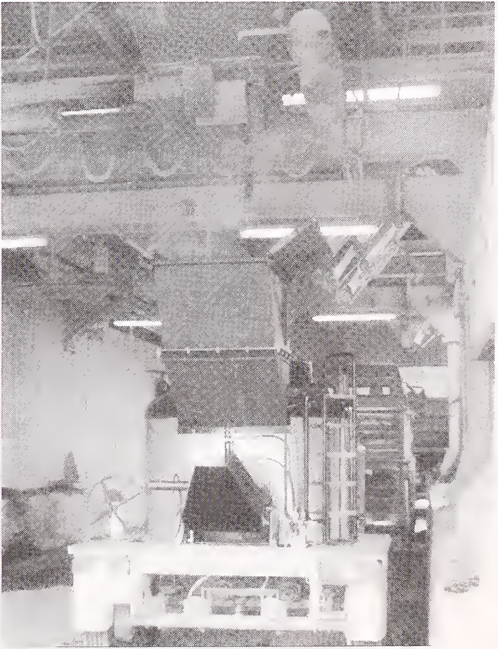
Photo 1 A General View of the Plant12
- The Truck Mounted Transporters: The action of mixing of the components shall continue in the transporter after the mix from the plant is poured into it. It shall have an insulated tilting steel drum provided with rotating mixing arm and heating facilities with oil fired burners for the circulating thermic oil in its jacket. Till the mix is poured on the surface to be covered by opening the outlet and by tilting the drum; the mixing operation shall continue and ensure a homogenous hot mix.
- The Paver: This shall help in spreading and floatation the plastic mix uniformly on the surface to the desired width and thickness at correct grade and camber through its heated, distortion free steel float and turning sword distributors. (Photo 2)
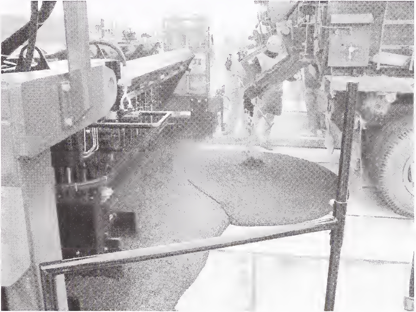
Photo 2 A View of Paver
It shall be operated by a diesel engine and by means of hydraulic system. (Photo 3)
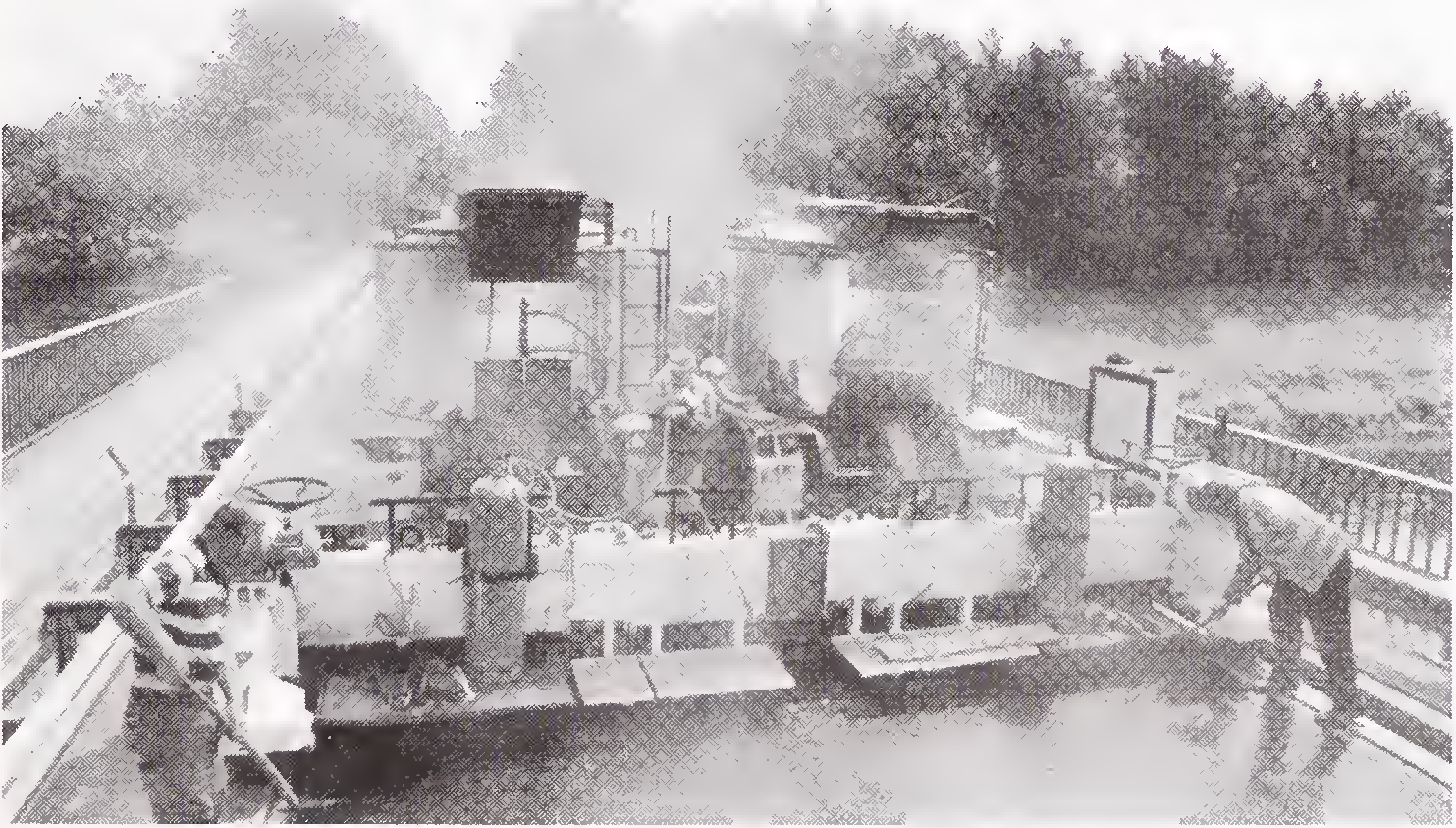
Photo 3 Paver in Operation13
The heating of the float shall be done by LPG fuelled, infrared heaters attached to it. The special profiling with precision and smoothing zones on the float or the working bar shall guarantee optimum layering conditions and results. The single extension pieces shall be changed according to the desired working width. (Photo 4)
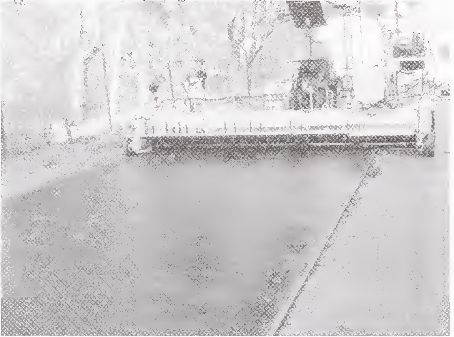
Photo 4 A View of Finished Work
- Salient Features of the Plant: It shall be possible to achieve a progress of about 2500 sqm. of work in a day with a single plant and paver. It shall produce about 15 to 20 tonnes of mix per hour.
- Cover Chips: The cover chips passing 4.75 mm and retained on 2.36 mm sieve, should be coated with 2 percent VG 10 grade bitumen prior to the start of production each day. The bitumen coated chips shall be stored in concrete bins adjacent to the plant area and turned over periodically with a front end loader to prevent a build-up of heat.
- Mechanized Chip Spreader: To prevent skidding of vehicles in wet weather conditions it shall be mandatory to adopt the method of applying uniform size bitumen chips, on the laid surface, through a power driven chip spreader. This unit shall be place about 3 m behind the screed and shall apply the chips for anti-skid. The chips are carried in a supplied in a supply hopper and mechanically delivered by a feed roll to the pavement at a rate of 5.4 - 8.1 kg per sqm. The chips can also be spread by hand from the back platform of the chip spreader to those areas that lacked sufficient cover.14