This library of books, audio, video, and other materials from and about India is curated and maintained by Public Resource. The purpose of this library is to assist the students and the lifelong learners of India in their pursuit of an education so that they may better their status and their opportunities and to secure for themselves and for others justice, social, economic and political.
This item has been posted for non-commercial purposes and facilitates fair dealing usage of academic and research materials for private use including research, for criticism and review of the work or of other works and reproduction by teachers and students in the course of instruction. Many of these materials are either unavailable or inaccessible in libraries in India, especially in some of the poorer states and this collection seeks to fill a major gap that exists in access to knowledge.
For other collections we curate and more information, please visit the Bharat Ek Khoj page. Jai Gyan!
MEMBERS OF THE SPECIFICATIONS AND STANDARDS COMMITTEE
| 1. | N. Sivaguru (Convenor) |
Addl. Director General (Roads), Ministry of Transport, Department of Surface Transport |
| 2. | I. J. Mamtani | Superintending Engineer (Roads), Ministry of Transport Department of Surface Transport |
| 3. | V. K. Arora | Chief Engineer (Roads), Ministry of Transport, Department of Surface Transport |
| 4. | R. C. Arora | Manager (Asphalt), Hindustan Petroleum Corporation, Bombay |
| 5. | R. T. Atre | Secretary to the Govt. of Maharashtra (1), PW & H Department |
| 6. | Y. N. Bahl | Director, Technical Education, Chandigarh |
| 7. | S. P. Bhargava | Superintending Engineer (Roads), P.W.D., Rajasthan |
| 8. | P. C. Bhasin | Adviser (Technical), Hooghly Bridge Commissioner’s, Calcutta |
| 9. | B. M. Das | Engineer-in-Chief-cum-Secretary to the Govt. of Orissa |
| 10. | Dr. P. Ray Choudhary | Head, Bridges Division, Central Road Research Institute |
| 11. | Dharm Vir | Chief Engineer (NH), and Hill Road Co-ordinator, U.P., P.W.D. |
| 12. | Dr. M. P. Dhir | Director, Central Road Research Institute |
| 13. | T. A. E. D’sa | Chief Engineer, Concrete Association of India, Bombay |
| 14. | V. P. Gangal | Superintending Engineer, New Delhi Municipal Committee |
| 15. | Titty George | Chief Engineer (B & R) & Ex-officio Addl. Secy to the Govt. of Kerala |
| 16. | R.A. Goel | Chief Engineer (NH), Haryana P.W.D. B & R |
| 17. | Y. C. Gokhale | Deputy Director & Head, Bitumen Division, Central Road Research Institute |
| 18. | I. C. Gupta | Engineer-in-Chief, Haryana P.W.D. B&R (Retd.) |
| 19. | S. S. Das Gupta | Manager (Bitumen), Indian Oil Corporation Limited, Bombay |
| 20. | M. B. Jayawant | Neelkanth, 24, Carter Road, Bandra, Bombay |
| 21. | P.C. Jain | Director (Design), E-in-C’s Branch, Kashmir House, New Delhi |
| 22. | L. R. Kadlyali | Chief Engineer (Planning), Union Ministry of Transport, Department of Surface Transport |
| 23. | Dr. S. K. Khanna | Secretary, University Grants Commission |
| 24. | G. P. Lal | Chief Engineer (Buildings), Technical Secretariat, Patna |
| 25. | Dr. N. B. Lal | Head, Soil Stabilization and Rural Roads Division, Central Road Research Institute |
| 26. | P. K. Lauria | Chief Engineer-cum-Housing Commissioner, Rajasthan State Housing Board |
| 27. | K. S. Logavinayagam | 181-B, 54th Street, Ashok Nagar, Madras |
| 28. | J. M. Malhotra | Secretary to the Govt. of Rajasthan P.W.D. |
| 29. | P. J. Mehta | Secretary to the Govt. of Gujarat B & C Department (Retd.) |
IRC : 92-1985
Published by
THE INDIAN ROADS CONGRESS
Jamnagar House, Shahjahan Road,
New Delhi-110 011
1985
Price Rs.80/-
(Plus Packing & Postage )
GUIDELINES FOR THE DESIGN OF INTERCHANGES IN URBAN AREAS
Grade separation is a form of intersection in which one or more conflicting movements of intersecting highways are segregated in space. An interchange is a grade separation with connecting roadways which allow route transfer between the intersecting highways. An interchange is therefore, the highest form of intersection design. It should, however, be understood that interchanges are essentially intended for highways carrying predominantly fast moving motorised traffic
The type of interchange, the shape and pattern of the interchange ramps for the various turning movements, and their design are governed by several factors such as the importance of the intersecting highways, the number of intersccting legs, the design volumes of through and turning traffic movements including their composition, the design speeds, available right-of-way and topography. Interchanges, therefore, are necessarily designed individually in light of the above considerations. This publication gives guidelines for helping the designer in developing appropriate designs for interchanges under different situations in urban areas.
Interchanges are costly and a treatment of this type cannot be justified unless the benefits likely to accrue to the community are so high as to exceed the high cost associated with such improvements.
The Traffic Engineering Committee at its meeting held in October, 1977 while considering a draft on the subject prepared by Shri A.K. Bandopadhyaya, set up a Subcommittee to finalise the document. On the authorisation of this Subcommittee, the draft was finalised jointly by S/Shri A.K. Bhattacharya and D. Sanyal. This document was considered by the Traffic Engineering Committee at its meeting held in September, 1982 when it decided that the document may be revised by Shri K. Arunachalam in light of the comments received from the various members. The document as revised by Shri K. Arunachalam was approved by the Traffic Engineering Com-1
mittee (personnel given below) in their meeting held at Nagpur on the 11th January, 1984.
| Dr. N.S. Srinivasan | ... | Convenor |
| D. Sanyal | ... | Member-Secretary |
| Prof. G.M. Andavan | R. Thillainayagam | |
| K. Arunachalam | V.V. Thakar | |
| A.K. Bandopadhyaya | D.L. Vaidya | |
| P.S. Bawa | P.G. Valsankar | |
| A.K. Bhattacharya | P.R. Wagh | |
| A.G. Borkar | P.D. Wani | |
| P. Das | K. Yegnanarayana | |
| T. Ghosh | C.E. (N.H.), Kerala | |
| Dr. A.K. Gupta | Director, Transport Research, Ministry of Transport (R.C. Sharma) | |
| Jogindar Singh | ||
| Dr. C.E.G. Justo | ||
| L.R. Kadiyali | The Chief, Transport & Communications Board, B.M.R.D.A. | |
| Dr. S.K. Khanna | ||
| K.S. Logavinayagam | (R.Y. Tambe) | |
| P.J. Mehta | S.E., Traffic Engg. & Management Cell, Madras | |
| Dr. S.P. Palaniswamy | ||
| S.M. Parulkar | (V. Gurumurthy) | |
| P. Patnaik | President, Indian Roads Congress | |
| Dr. S. Raghava Chari | (V.S. Rane) -Ex-officio | |
| Prof. M.S.V Rao | Director General (Road Development) & Addl. Secy. to the Govt. of India (K.K. Sarin) -Ex-officio | |
| Prof. N. Ranganathan | ||
| Dr O.S. Sahgal | ||
| D.V Sahni | Adviser, Indian Roads Congress | |
| Dr. S.M. Sarin | (P C. Bhasin) -Ex-officio | |
| H.C. Sethi | Secretary, Indian Roads Congress | |
| H.M. Shah | (Ninan Koshi) -Ex-officio |
The revised guidelines were approved by the Specifications and Standards Committee in their meeting held at New Delhi on the 21st August, 1985 subject to necessary changes suggested by the Committee.
Later on the above guidelines were considered and approved by the Executive Committee in their meeting held a New Delhi on the 22nd August, 1985. The Council in their 114th meeting held at Panaji (Goa) on the 6th September, 1985 approved the same for being published by the Indian Roads Congress.2
A grade separation is a crossing of two or more highways, a highway and a rail road, or a highway and any other type of facility such as a pedestrain walk way or a bicycle way.
An inter-connecting roadway or any connection between highways at different levels, or between parallel highways, on which vehicles may enter or leave a designated roadway. The components of a ramp are a terminal at each end and a connecting road, usually with some curvature and on a grade.
An interchange is a grade separated intersection with connecting roadways (ramps) for turning traffic between highway approaches.
Interchanges, in general, are expensive to construct and a major factor influencing the cost is the type of arrangement made for the various traffic movements. The arrangement may range from separating only one traffic movement from other to the complete separation of each traffic movement from every other movement so that only merging and diverging movements remain. Similarly, the vehicle operating cost will vary depending on the type of ramp arrangement, from direct conflict—free connections to indirect connections involving extra travel distance. As interchanges are custom designed to suit the prevailing conditions, it will be necessary to carry out cost-benefit study taking into account the total transportation cost, i.e. the cost of construction, maintenance and vehicle operation, to evaluate the technoeconomic merits of the individual cases before a final decision is taken. However, the following points may be helpful in guiding the choice of an interchange at the preliminary planning stage:
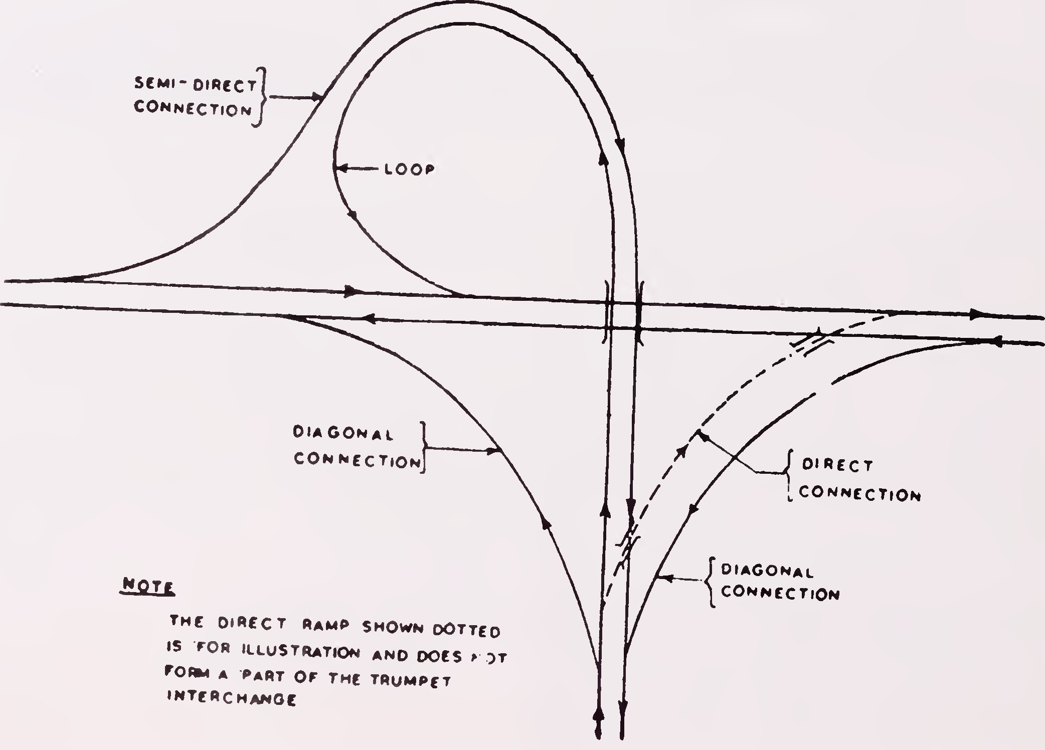
Interchanges are generally described by the pattern of the various turning roadways or ramps which determine their geometric configuration. The ramps can be broadly classified into the following four basic types, also illustrated in, Fig. 1.
Fig. 1. Different types of ramps
The common geometric configurations of interchanges are the trumpet, diamond, cloverleaf, rotary and directional, see Figs. 1 and 2 for typical examples. Within each type of interchange, there can be several variations such as split diamond, partial cloverleaf, etc. depending on the ramp arrangements. The broad operational characteristics of each of the common interchange types are brought out in paras 4.3. to 4.7.
Fig. 1, shows a typical 3-leg interchange which takes the shape of trumpet. This is the simplest interchange form adaptable to 'T' or 'Y' intersections. Of the two right turning movements, one is negotiated by a loop while the other is by a semi-direct connection. Diagonal ramps are provided for left turning movements. There can be several variations of the design depending on the type of connection provided. The type of connection provided for the right turning movements should be based on traffic volumes. The ramps catering for heavy traffic volumes should preferably be provided with direct connections. Fig. 1, illustrates the replacement of a loop ramp by a direct connection.
Fig. 2(a) shows a typical diamond interchange. Diamond interchange is the simplest of 4-leg interchange designs and is particularly adaptable for major-minor highway intersections. The ramps which provide for one way movement are usually elongated along the major highway and may be curved or parallel to the major highway. The ramp terminals on the minor road are at-grade intersections providing for right and left turning movements. These at-grade intersections may be controlled by signals if warranted by traffic volumes or in the absence of adequate sight distance.
The diamond design requires minimum land, involves only a small extra travel distance for right turning traffic, is the least costly, and will be found ideal for most of the cases both in urban and rural areas. However, this type of interchange has the demerit of limited capacity because of the at-grade terminals on the minor road. The situation can be improved by widening the cross5
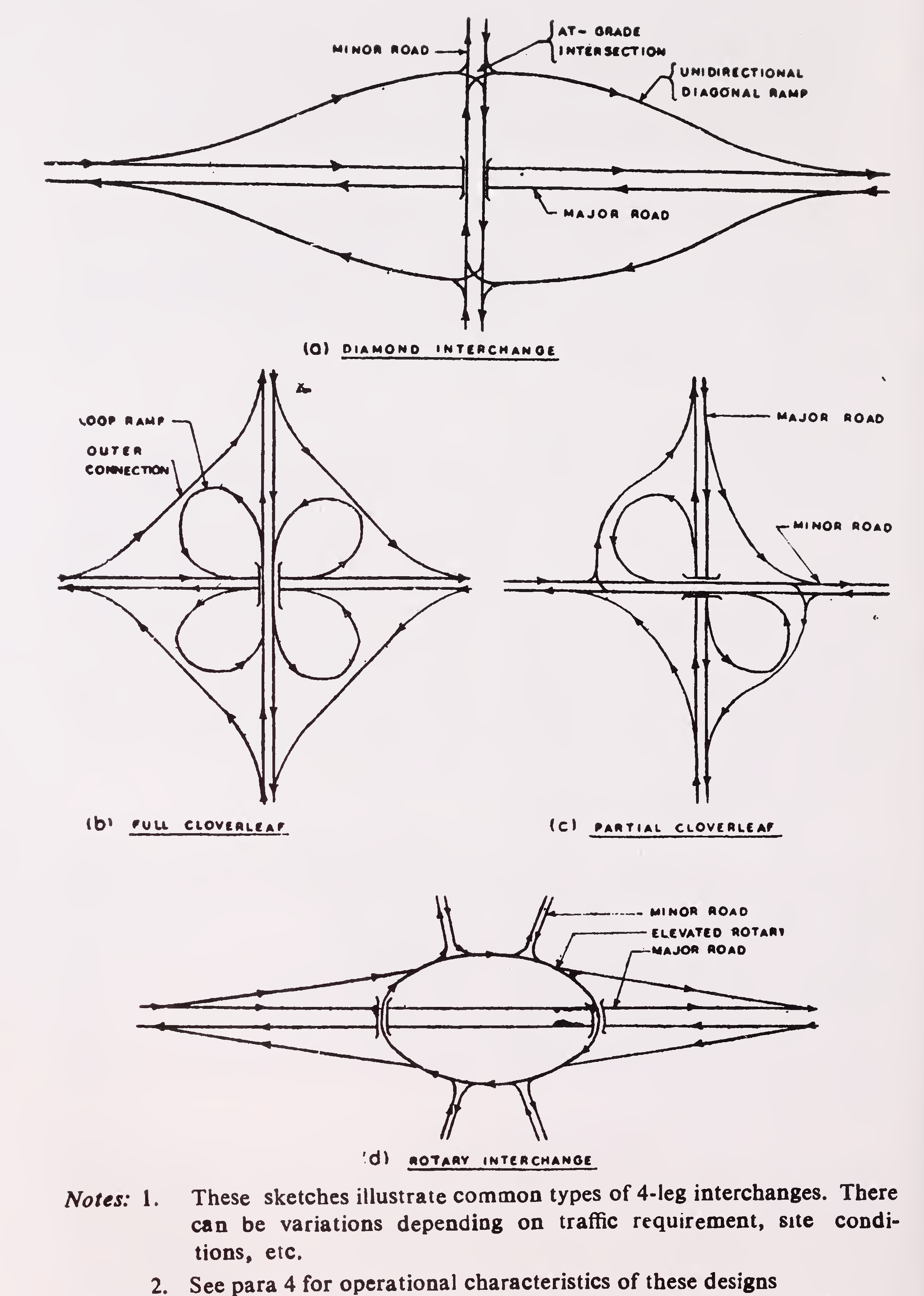
Fig. 2. Typical 4-leg interchange designs6
road through the interchange area, or the ramp terminals, or both. Further improvements can be effected by having a split diamond or 3-level diamond, but this will involve more than one bridge.
Fig. 2 (b), shows a typical cloverleaf interchange. The design consists of one loop ramp for right turning traffic and one outer connection for left turning traffic in each quadrant. Vehicles desiring to turn right are required to turn left through about 270 degrees before attaining the desired direction.
This type of interchange provides for continuous movement to all interchanging traffic and is particularly suitable for the crossing of two major roads of equal importance in rural areas. In urban areas, this type of interchange tends to use up too much of costly urban space.
Cloverleaf design involves appreciable extra travel distance for the right moving traffic and requires a large space. Though all crossing movement conflicts are eliminated, a weaving section is created between the exit and entry points near the structure along each direction of travel on the intersecting roads. These weaving sections constitute a critical element in the design, and unless these are designed to have adequate length and capacity, there may be serious loss in capacity besides increased hazards.
In cases where at-grade crossing on one of the roads can be tolerated, full cloverleaf development will not be required. For such cases, partial cloverleaf which is a modification that combines some elements of a diamond interchange with one or more loops to eliminate only the more critical conflicts can be adopted. A number of variations are possible for meeting the different site conditions and traffic distribution. Fig. 2 (c), depicts one design of partial cloverleaf.
This type of design is particularly useful where a number of roads intersect at the interchange and in locations where sufficient land is available. It requires the construction of two bridges and generally necessitates more land than for a diamond layout. The main highway goes over or under the rotary intersection and turning movements are accommodated by the diagonal ramps. Fig. 2 (d), shows a typical rotary interchange.
The capacity of a rotary interchange is similar to that7
of at-grade rotary. High speed operations cannot be maintained on the minor road because of the usually short weaving distances. It can, however, operate satisfactorily at low speeds. Also this type of design entails only a little additional travel distance for interchanging traffic which is a specific advantage when slow moving traffic is present.
Directional interchanges have ramps for right turning traffic which follow the natural direction of movement. This type of design requires more than one structure, or a 3-level structure. Though operationally more efficient than other designs, these generally turn out to be very expensive.
Design speed of a ramp should be related to the design speed of the major intersecting highway. Ramp design speeds corresponding to the highway design speeds of 80 and 100 km/h are given in Table 1. Design speeds of 80 km/h are applicable to interchanges on urban highways.
Minimum radius of horizontal curve and sight distance corresponding to the design speeds are also indicated in Table 1. The sight distance values are for safe stopping conditions and should be ensured both in the horizontal and vertical directions. The sight distance should be measured between two points, one at a height of 1.2 m above the road level representing the driver’s eye and the other 0.15 m above the road level denoting the object.
Horizontal curvature of ramps should preferably be of circular curve with transitions at either ends. Where this is not feasible, 2-centred compound curves may be employed provided that the radius of any curve is not less than one-half the radius of the preceding curve.
Ramp profiles usually consist of a section of tangent grade between two vertical curves, valley curve at the lower end and summit curve at the upper end. The tangent grades on ramps should be as flat as feasible, and desirably, it should be limited to a maximum of 4 per cent and in no case should it exceed 6 per cent.8
| Particulars | Design values for major highway designs speed of | For loop ramps | ||||
|---|---|---|---|---|---|---|
| 80 km/hr | 100 km/hr | |||||
| Minimum | Desirable | Minimum | Desirable | Minimum | Desirable | |
| Ramp design speed (km/h) | 40 | 50 | 50 | 65 | 30 | 40 |
| Radius of curvature (m) | 60 | 90 | 90 | 155 | 30 | 60 |
| Stopping sight distance (m) | 45 | 60 | 60 | 90 | 25 | 45 |
Notes : 1. The major highway design speeds of 80 km/h is appropriate for highways in urban areas. 2. The radius of curvature values have been worked out for a maximum superelevation of 7 per cent. |
||||||
| Sl. No. | Design speed (km/h) | Safe stopping sight distance (m) |
Length of vertical curve for safe stopping sight distance (m) | Absolute minimum length of vertical curve (m) |
|
|---|---|---|---|---|---|
| Summit curve | Valley curve | ||||
| 1 | 2 | 3 | 4 | 5 | 6 |
| 1. | 30 | 30 | 2.0A | 3.5A | 15 |
| 2. | 40 | 45 | 4.6A | 6.6A | 20 |
| 3. | 50 | 60 | 8.2A | 10 A | 30 |
| 4. | 65 | 90 | 18.4A | 17.4A | 40 |
| 5. | 80 | 120 | 32.6A | 25.3A | 50 |
| 6. | 100 | 180 | 73.6A | 41.5A | 60 |
Notes : 1. 'A’ in columns 4 and 5 is the algebraic difference in grades expressed as percentage. 2. Where the length given by columns 4 or 5 is less than that given in column 6, the latter value should be adopted.9 | |||||
The vertical curves at either ends of the ramp should be designed to provide for atleast the safe stopping sight distance corresponding to the design speed of the ramp. The length of vertical curves for design speeds of 30 to 100 km/h are given in Table 2.
The ramp may be for one-way or two-way operation. If for two-way, divided type of cross-section should be used with a minimum width of 1.2 m for the median.
The width of pavement to be provided for each way will depend on the design hour traffic volume expected to use the ramp. The capacity for unidirectional flow given below will be helpful in choosing the appropriate pavement width. The minimum width of shoulders should be 2 m of which at least one metre should be paved. The shoulders should be properly delineated by means of pavement markings (see IRC: 35 ‘Code of Practice for Road Markings with Paints), different surfacing material, etc.
| Pavement width | Capacity, pcu's/hour |
| 1. Single lane, 3.75 m wide | 1500 |
| 2. Intermediate lane, 5.5 m wide | 2000 |
| 3. Two-lanes, 7.0 m wide | 2500 |
Note: The above capacity figures are for roads provided with one metre wide paved shoulders on either side. |
|
Ramp terminal is that portion adjacent to the through travelled way including speed change lanes, tapers and islands. Free-flow type ramp terminals where ramps traffic merges with (entrance terminal) or diverges from (exit terminal) high speed through highway at flat angles should invariably be provided with speed change lanes i.e. acceleration lane at entrance terminal and deceleration lane at exit terminal. The speed change lanes should be carefully sited to ensure that they are not hidden from the view of approaching traffic by horizontal or vertical curves.
The entrance terminal should provide for sufficient length of acceleration lane to enable a driver to increase his speed from that on the turning ramp road-way to that of the operation speed of the highway as also to provide manoeuvring space so that the driver can watch and take advantage of an opening in the adjacent stream of through traffic and10
move laterally into it. At the end of the acceleration lane, it is important that there should be no kerb or other obstruction which might be dangerous for a driver unable to merge with the traffic stream on the near side lane within the length of the acceleration lane.
Acceleration lanes are designed in two general forms, namely, the direct taper type and the parallel type. The taper type works on the principle of direct entry at a flat angle and part of the lane is separated from the through pavement of the highway. Though this form is generally preferred by the vehicles, it requires more space with the turning curve located farther away from the edge of the main highway. The parallel type has an additional lane built on the highway itself for speed change purposes. Both types will operate satisfactorily if designed properly, though the direct taper type will be appropriate for most cases.
The length of acceleration lane is governed by the difference between the running speeds of the entrance curve of the ramp and of the highway. The minimum and desirable lengths of acceleration lane are given in Table 3. These lengths are particularly influenced by gradient. On down gradient, the length given in Table 3 may be reduced to (1-0.08G) times and on up gradient increased to (1+0.12G) times, where G is the gradient expressed as a percentage.
| Type of lane | Length including taper (m) | |
|---|---|---|
| Desirable | Minimum | |
| Acceleration lane | 250 | 180 |
| Deceleration lane | 120 | 90 |
The exit terminal should be provided with sufficient length of deceleration lane to enable vehicles leaving the highway at high speeds to reduce their speeds to negotiate the turning curve on the exit ramp. Similar to acceleration lane, deceleration lane can be of two forms, namely, direct taper type and parallel type. Recommended minimum and desirable lengths of deceleration lane are also indicated in Table 3. Where the11
lanes are in up gradient, their length may be reduced to (1-0.03G) times and while on down gradient increased to (1+0.06G) times the values given in the Table 3, where G is the gradient expressed as a percentage.
Typical designs for exit terminal provided with deceleration lane are also shown in Fig. 3. It may be noted that the nose separating the through lane from the turning lane is off-set from the edge of the through lane by 2 m to enable an errant vehicle which has inadvertently left the through lane to return with minimum disruption to through traffic. It is also important that the “Core” area formed by the edges of the through and the turning lanes immediately beyond the point of divergence should be kept free of all hazardous obstructions so as to provide a clear recovery area for out of control vehicles.
Weaving manoeuvres take place at interchanges where successive entry and exit terminals are located near to each other as in a cloverleaf design. The capacity of the weaving sections which depends on the length, the number of weaving lanes and the proportion of weaving traffic should be adequate enough for performing the weaving manoeuvre without appreciable loss in speed. The recommended desirable and minimum lengths of weaving sections are 300 m and 200 m respectively.
For underpass roadways, desirably the full roadway width at the approaches should be carried through the underpass. This implies that the minimum lateral clearance (i.e. the distance between the extreme edge of the carriageway and the face of nearest support, whether solid abutment pier or column) should equal the normal shoulder width. For more details on clearances, reference may be made to IRC : 54-1974 “Lateral and Vertical Clearance at Underpasses for Vehicular Traffic”.
For overpass structures, the clearances are not that critical as in the case of underpasses since the drivers do not generally get the feeling of constriction. A cross-section with 225 mm wide kerb and open-type parapet will generally be suitable for most cases.
Vertical clearance at underpass should be minimum 5.5 m in urban areas, after making allowance for any future raising/strengthening of the underpass roadway.12
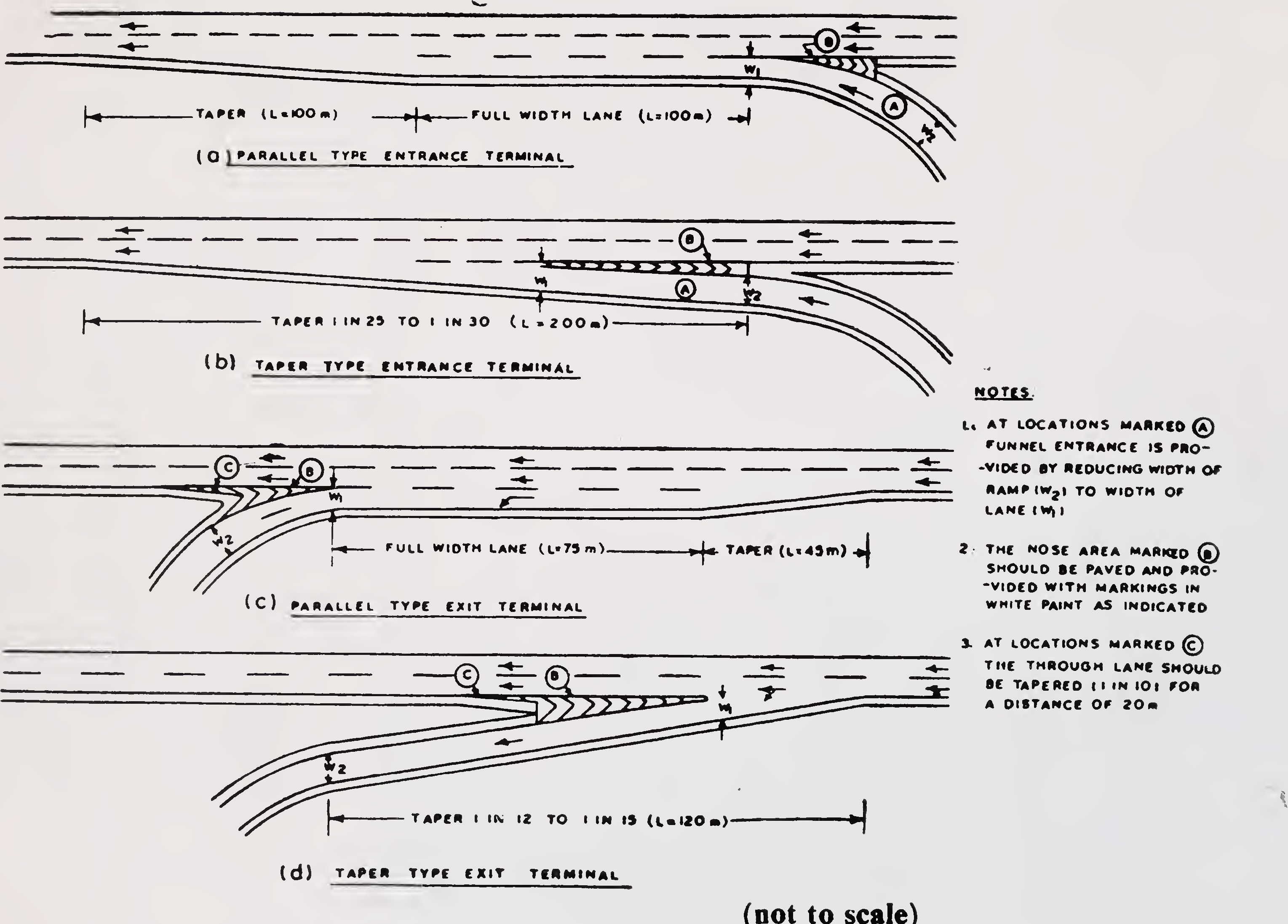
Fig. 3. Typical designs for entry and exit terminals13
Selection of the most appropriate type of interchange for the prevailing conditions is an important step in design. The specific form or type of interchange will depend on the physical conditions of the site such as topography, available right-of-way, land-use and developments alongside the intersecting roads, expected volumes of through and turning traffic including their composition, orientation of the intersecting highways, etc.
At an interchange, not all the traffic streams need be grade separated in most of the cases. A study of the design peak hour traffic on all the arms and the directional distribution will clearly bring out the major conflict points and the traffic streams which should be grade separated to provide for free flow conditions and satisfy the capacity requirements. For design traffic projection, a horizon of 20 years may be adopted. For directional distribution of traffic in the design year, unless the factors expected to change the pattern are known, a distribution similar to the one derived from the current traffic surveys may be adopted. From the traffic data, design peak hour traffic flow diagram should be prepared, a sample of which is shown in, Fig. 4 (a). Once a particular type of interchange is chosen for preliminary design, a traffic distribution diagram should be prepared for facilitating the design of the individual components. A diagram for a typical diamond interchange is shown in, Fig. 4 (b) for illustration. For simplicity, this diagram shows only the fast traffic in terms of pcu’s. Similar diagram should be prepared for slow traffic for checking the adequacy of design. For converting fast vehicles into pcu’s, the following equivalency factors may be adopted :
| Vehicle type | Equivalency factor | |
| 1. | Passenger car, tempo, auto-rickshaw, or agricultural tractor | 1.0 |
| 2. | Cycle, motor cycle or scooter | 0.5 |
| 3. | Truck, bus, or agricultural tractor-trailer unit | 3.0 |
Study of the physical conditions of the site should include:
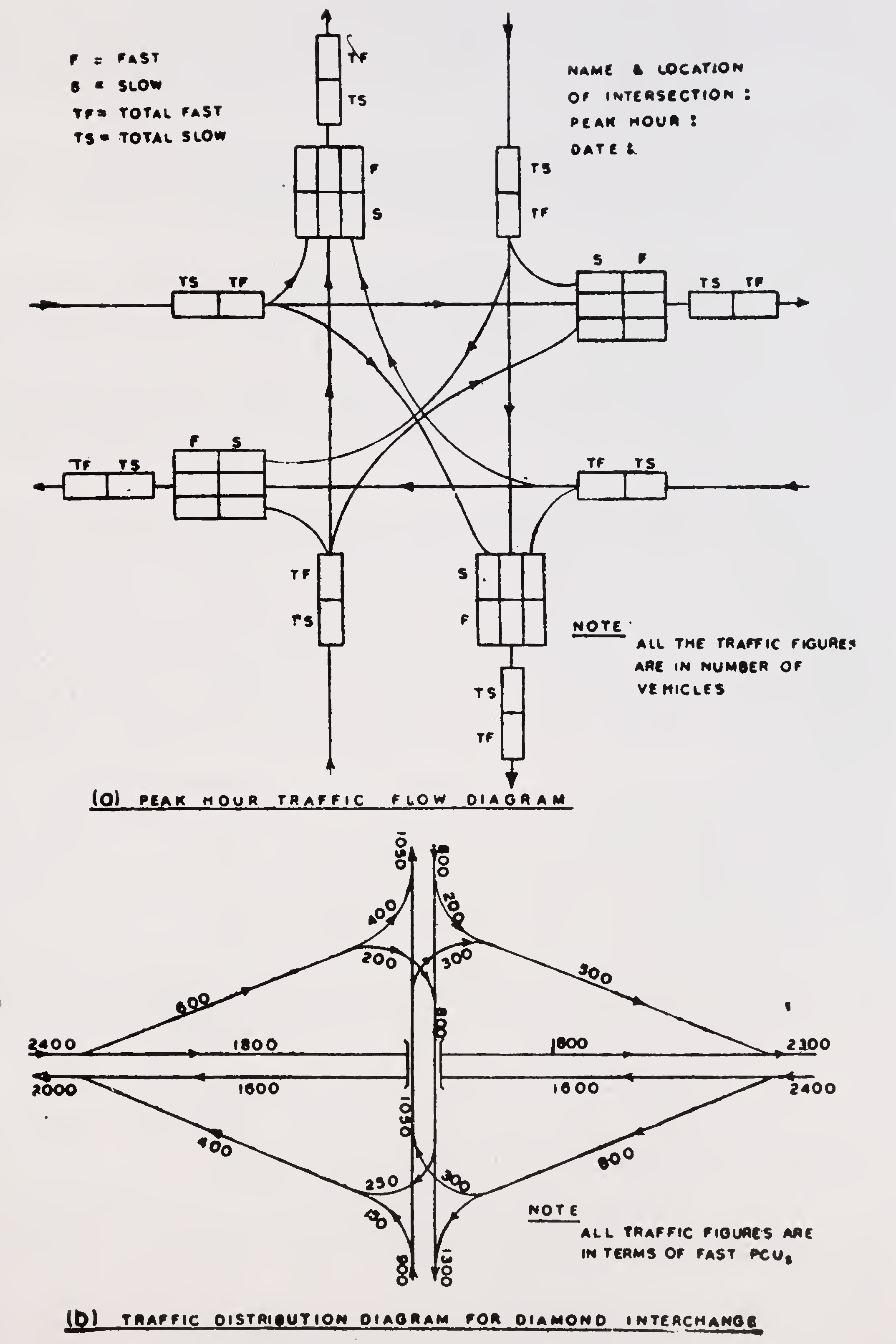
Fig. 4. Traffic flow diagrams15
where free flow type ramp terminals may be necessary. On a highway with frequent at-grade intersections, the ramp terminals should also be at-grade. Similarly, terminals on highways carrying more than 10 per cent slow traffic (i.e. carts, bicycles, etc.) should be at-grade.
Based on a study of the traffic data (para 6.1.2.) in conjunction with the considerations given in para 6.1.3. and the operational characteristics of the different types of interchanges explained in para 4, study sketches for a number of interchange designs which are suitable to meet the traffic needs and are practicable for the site conditions should be prepared. These should be examined and short listed for preparing preliminary plan and profile. While doing so, the following principles should be kept in view:
The design selected at this stage should be further evaluated for initial construction cost and cost of vehicle operation, and the best among the alternatives selected for final design.
The following factors should be kept in view while deciding on the road to fly-over the other road:
The ramp terminals should be located sufficiently away from the grade separation structure so that vehicles entering or leaving the highway have sufficient visibility distance for performing the turning manoeuvres with safety.
At-grade ramp terminals, as on the minor road in the case of diamond design, should be located at a distance equal to atleast the safe stopping sight distance corresponding to the design speed of that road.
As regards the free flow type ramp terminals, the distance between the structure and the nose of the exit terminal on the far side of the structure should at least be 75 m for exit drivers to have a good view of the terminals and leave the through lanes without undue hindrance to the through traffic. The corresponding distance for far side entrance terminals should be atleast 150 m to enable entrance drivers in having a clear view well back on the through road ahead or to their right. However, for terminals on the near side of the structure, this separation distance is not critical for entrance drivers since their view back along the highway is not affected by the structure. Such terminals could be located at a distance equal to the acceleration lane, and where this is not possible, at a distance of at least 15 m with the acceleration lane continuing through or over the structure.
The basic number of lanes should be uniform for a substantial length of the highway. The basic number of lanes to be used on the highway and the minmum number of lanes required for ramps are determined by a capacity analysis of the design traffic volumes. To realise efficient traffic operation through and beyond the interchange, there should be a balance in number of traffic lanes required on the highway and on the ramps. If additional traffic lanes are needed on the highway to maintain lane balance with the ramp, it should be accomplished by adding auxiliary17
lanes rather than changing basic number of lanes. Lane balance should be checked on the basis of the following principles:
Interchanges are essentially intended for highways carrying fast moving traffic. Slow moving traffic like carts and bicycles if present in appreciable numbers will cause serious obstruction to the free operation, particularly at the free-flow type ramp terminals. For example, the purpose of long acceleration lane will be completely lost even if one slow vehicle comes in the way of fast vehicles at the ramp terminal. Another major problem is the tendency on the part of the slow vehicles in not using detours in the form of indirect connections like loops and in finding shorter routes by cutting across the medians or in moving in the wrong direction, all leading to confusion and hazardous situation. Where slow traffic present in any of the intersecting highways is more than about 10 per cent, the classical forms of interchange designs will require modifications, particularly in respect of the following :
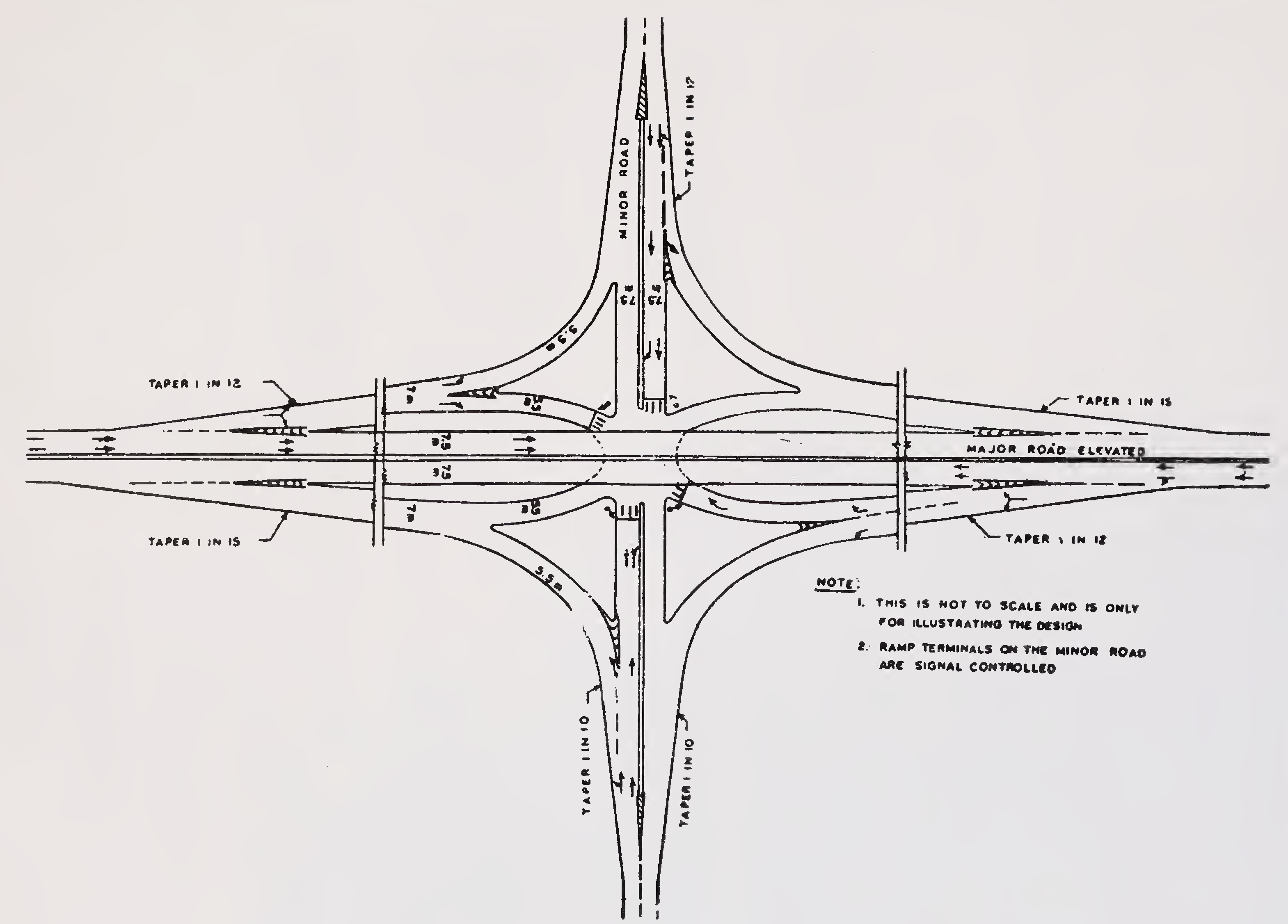
Fig. 5. Typical 4-leg interchange in urban area19
A typical design for an interchange in urban area having provisions for slow traffic is illustrated in, Fig. 5.
The signs on the interchanges should serve the following functions :
The size and lettering of interchange signs should correspond to the type of highway on which the interchange is situated. However, the letters, numerals, symbols and borders should be reflectorised for better visibility.
The signing plan showing the type and location of the different signs should be prepared simultaneously with the design of the interchange.
An interchange in an urban area is an integral part of the city strucuture and aesthetically it must be treated as such. The retaining walls and all other large and exposed concrete mass should be suitably softened. Perspective drawings, including scale models must be prepared so that best arrangements for landscaping could be developed.
For more information on landscaping of highways, reference may be made to IRC Special Publication : 21 ‘Manual on Landscaping of Roads’.20
| 30. | O. Muthachen | Poomkavil House, Somangalam, Punalur (Kerala) |
| 31. | P. K. Nagarkar | Chief Engineer & Director, Maharashtra Engineering Research Institute |
| 32. | K. K. Nambiar | Ramanalaya, 11, First Crescent Park Road, Adyar, Madras |
| 33. | T. K. Natarajan | Deputy Director & Head, Soil Mechanics |
| 34. | P. Patnaik | Division, Central Road Research Institute Chairman, Orissa Bridge Construction Corporation |
| 35. | Y. R. Phull | Deputy Director & Head, Roads Division, Central Road Research Institute |
| 36. | Rajinder Singh | Chief Engineer, Jammu P.W.D., B & R |
| 37. | G. Raman | Director (Civil Engg.), Indian Standards Institution |
| 38. | Prof. M. S. V. Rao | Head of the Deptt. of Traffic & Transportation, School of Planning & Architecture |
| 39. | V. S. Rane | Secy. to the Govt. of Maharashtra PW & H Department (Retd.) |
| 40. | A. K. Roy | Director, SURAD, Calcutta Metropolitan Development Authority |
| 41. | Maj. Gen. J. C. Sachdeva | Director General Border Roads |
| 42. | Dr. O. S. Sahgal | Principal, Punjab Engineering College, Chandigarh |
| 43. | Satish Prasad | AI-103, Safdarjung Enclave, New Delhi |
| 44. | A. Sankaran | Chief Engineer (Evaluation) Income Tax Department |
| 45. | Dr. A. C. Sarna | Head, Traffic Division, Central Road Research Institute |
| 46. | N. Sen | Chief Engineer, Ministry of Transport (Retd.) |
| 47. | G. M. Shonthu | Chief Engineer, Kashmir P.W.D., B & R |
| 48. | S. B. P. Sinha | Engineer-in-Chief-cum-Addl. Commissioner-cum-Spl. Secretary, Bihar P.W.D., B & R |
| 49. | J. S. Sodhi | Chief Engineer (South), Punjab P.W.D., B & R |
| 50. | Dr. N. S. Srinivasan | Executive Director, National Transportation Planning and Research Centre |
| 51. | Prof. C. G. Swaminathan | Director Central Road Research Institute (Retd.) |
| 52. | K. P. Nair | Research Manager, R & D Centre, Indian Oil Corporation Ltd., Faridabad |
| 53. | Ravinder Kumar | Director, U.P. P.W.D. Research Institute |
| 54. | C. D. Thatte | Director, Gujarat Engineering Research Institute |
| 55. | The Director (D. Mohan) | Highways Research Station, Madras |
| 56. | The Director (S.K. Dey Sarkar) |
R & B Research Institute, Pailan, West Bengal |
| 57. | The President, Indian Roads Congress (K. Tong Pang Ao) | -Ex-officio |
| 58. | The Director General (Road Development) & Addl. Secy. to the Govt. of India (K. K. Sarin) | -Ex-officio |
| 59. | The Secretary, Indian Roads Congress (Ninan Koshi) | -Ex-officio |